EP3203084A1 - Ventilatorrad und gebläseanordnung - Google Patents
Ventilatorrad und gebläseanordnung Download PDFInfo
- Publication number
- EP3203084A1 EP3203084A1 EP16153807.9A EP16153807A EP3203084A1 EP 3203084 A1 EP3203084 A1 EP 3203084A1 EP 16153807 A EP16153807 A EP 16153807A EP 3203084 A1 EP3203084 A1 EP 3203084A1
- Authority
- EP
- European Patent Office
- Prior art keywords
- fan wheel
- support
- rotation
- wheel according
- support means
- Prior art date
- Legal status (The legal status is an assumption and is not a legal conclusion. Google has not performed a legal analysis and makes no representation as to the accuracy of the status listed.)
- Granted
Links
Images

Classifications
-
- F—MECHANICAL ENGINEERING; LIGHTING; HEATING; WEAPONS; BLASTING
- F04—POSITIVE - DISPLACEMENT MACHINES FOR LIQUIDS; PUMPS FOR LIQUIDS OR ELASTIC FLUIDS
- F04D—NON-POSITIVE-DISPLACEMENT PUMPS
- F04D29/00—Details, component parts, or accessories
- F04D29/26—Rotors specially for elastic fluids
- F04D29/28—Rotors specially for elastic fluids for centrifugal or helico-centrifugal pumps for radial-flow or helico-centrifugal pumps
- F04D29/281—Rotors specially for elastic fluids for centrifugal or helico-centrifugal pumps for radial-flow or helico-centrifugal pumps for fans or blowers
-
- F—MECHANICAL ENGINEERING; LIGHTING; HEATING; WEAPONS; BLASTING
- F04—POSITIVE - DISPLACEMENT MACHINES FOR LIQUIDS; PUMPS FOR LIQUIDS OR ELASTIC FLUIDS
- F04D—NON-POSITIVE-DISPLACEMENT PUMPS
- F04D25/00—Pumping installations or systems
- F04D25/02—Units comprising pumps and their driving means
- F04D25/08—Units comprising pumps and their driving means the working fluid being air, e.g. for ventilation
- F04D25/082—Units comprising pumps and their driving means the working fluid being air, e.g. for ventilation the unit having provision for cooling the motor
-
- F—MECHANICAL ENGINEERING; LIGHTING; HEATING; WEAPONS; BLASTING
- F04—POSITIVE - DISPLACEMENT MACHINES FOR LIQUIDS; PUMPS FOR LIQUIDS OR ELASTIC FLUIDS
- F04D—NON-POSITIVE-DISPLACEMENT PUMPS
- F04D29/00—Details, component parts, or accessories
- F04D29/26—Rotors specially for elastic fluids
- F04D29/28—Rotors specially for elastic fluids for centrifugal or helico-centrifugal pumps for radial-flow or helico-centrifugal pumps
- F04D29/281—Rotors specially for elastic fluids for centrifugal or helico-centrifugal pumps for radial-flow or helico-centrifugal pumps for fans or blowers
- F04D29/282—Rotors specially for elastic fluids for centrifugal or helico-centrifugal pumps for radial-flow or helico-centrifugal pumps for fans or blowers the leading edge of each vane being substantially parallel to the rotation axis
-
- F—MECHANICAL ENGINEERING; LIGHTING; HEATING; WEAPONS; BLASTING
- F04—POSITIVE - DISPLACEMENT MACHINES FOR LIQUIDS; PUMPS FOR LIQUIDS OR ELASTIC FLUIDS
- F04D—NON-POSITIVE-DISPLACEMENT PUMPS
- F04D29/00—Details, component parts, or accessories
- F04D29/58—Cooling; Heating; Diminishing heat transfer
- F04D29/5806—Cooling the drive system
-
- F—MECHANICAL ENGINEERING; LIGHTING; HEATING; WEAPONS; BLASTING
- F04—POSITIVE - DISPLACEMENT MACHINES FOR LIQUIDS; PUMPS FOR LIQUIDS OR ELASTIC FLUIDS
- F04D—NON-POSITIVE-DISPLACEMENT PUMPS
- F04D29/00—Details, component parts, or accessories
- F04D29/26—Rotors specially for elastic fluids
- F04D29/28—Rotors specially for elastic fluids for centrifugal or helico-centrifugal pumps for radial-flow or helico-centrifugal pumps
- F04D29/30—Vanes
Definitions
- the invention relates to a fan wheel for conveying a gaseous fluid, with a plurality of blades, which are arranged in a predeterminable angular pitch in an annular volume around a rotation axis and which are fixed with their axial, opposite end portions respectively to support means, wherein a first carrier means as a disk-shaped Ronde is formed coaxially to the axis of rotation and comprises a hub assembly and wherein a second carrier means is formed as a ring coaxial with the axis of rotation. Furthermore, the invention relates to a blower arrangement
- a fan wheel may be designed as a radial fan, in particular with backward curved blades, or as a drum impeller, as for example from DE 1 628 336 A is known.
- the Drummellaufrad consists of a large number of narrow slats, which form the blades of the wheel and which are mounted between two end rings whose radius is substantially greater than the width of the slats, so that a drum-shaped construction is formed, suitably with a Hub is connected, for example by means of a circular plate which is fixed to the slats at the center.
- the object of the invention is a fan wheel with improved aerodynamics and improved strength properties and to provide a blower assembly with increased range of use.
- a coaxially formed to the axis of rotation support disk is arranged, which forms an annular gap with the first support means, wherein the support disk is penetrated by at least one inlet opening, which allows a radially outwardly directed fluid flow in the annular gap.
- a space volume of the annular gap delimited by the first carrier means and by the support disk has an axial extent along the axis of rotation which is considerably smaller than the axial extent of the annular space volume determined by the two carrier means and in which the blades are arranged are.
- the axial extent of the annular gap along the axis of rotation is less than 20 percent, in particular less than 10 percent, of the axial extent of the annular space volume. This ensures that a fluid flow, which flows through the annular gap in the radial direction to the outside during a rotation of the fan wheel about the axis of rotation, is considerably less than a fluid flow which flows through the annular volume volume in the radial direction to the outside.
- a mass flow of a main fluid flow through the annular space volume is at least 5 times, in particular at least 10 times, greater than the mass flow of a secondary fluid flow through the annular gap.
- the fluid flow through the annular gap can be used for heat removal by a drive motor which is used to drive the fan wheel.
- the support disk is connected to the hub assembly.
- an advantageous introduction of force and torque is ensured by the hub assembly on the support disk, whereby an advantageous power flow is ensured in the fan wheel.
- the necessary for an advantageous concentricity of the fan wheel centering of the support plate is simplified by the connection of the support disk with the hub assembly.
- the support disk is directly connected to the first carrier means.
- the support disk and the first support means form a stable composite, which leads to a considerable increase in the stability of the fan wheel with a suitable design of the support disk and the first support means, without requiring a considerably larger material use would be required.
- the typically designed as a stamped sheet metal blank first carrier means is carried out in view of the connection with the support disk with a reduced material thickness and, preferably formed as stamped sheet metal blank, support plate has a material thickness which is similar to the material thickness of the first support means, in particular is identical to the material path of the first carrier.
- the support disk and the first carrier means are materially interconnected, for example by welding, in particular reader welding, and / or gluing.
- the projections are geometrically adapted with one of the respective opposite surface facing end face on a geometry of the opposite surface, which may be preferably flat.
- the projections have a main extension formed in the radial direction.
- the projections have a dual function which, in addition to the precise spacing and stable connection of the support disk and the first support means, also comprises a guiding action for the fluid flowing through the annular gap.
- the projections are arranged on radial lines which extend from the axis of rotation in the radial direction extend to the outside.
- the projections occupy an offset and / or an acute angle with the radial lines or at least partially curved.
- the support disk of several, arranged in the same angular pitch to the rotation axis, in particular congruent trained, inlet openings interspersed, between which radial spokes are extended from the hub assembly to a radially outer annular region of the support disk.
- the task of the inlet openings is to allow an axial inflow of fluid into the annular gap during a rotation of the fan wheel.
- the inlet openings are congruent, ie geometrically congruent, and are arranged with respect to the axis of rotation in the same angular pitch to each other.
- the inlet openings are bounded in the circumferential direction in each case by radial spokes, which are preferably web-shaped and in particular extend along radial lines which extend radially outward from the axis of rotation. Furthermore, it can be provided that the inlet openings are bounded by a radially inwardly arranged, circular-segment-shaped edge and / or by a radially outwardly arranged, circular-segment-shaped edge.
- guide projections, in particular corrugations, of the first support means are extended along the radial spokes to the radially outer annular region, in particular up to a maximum diameter of the radially outer annular region.
- This ensures a fluid-conducting function for the fluid flow in the annular gap.
- the Fluid in its flow movement starting from the inlet opening, which is formed in a radially inner region of the support disk, up to the radial exit from the annular gap always out with the help of the respective guide projection in aerodynamically favorable manner.
- support projections in particular beads, are formed, which are fixed to an opposite surface of the support disk or the first support means are.
- These support projections serve as additional conducting means for the fluid flow in the annular gap and also contribute to the formation of a stable composite of support disk and first carrier means.
- the support disk in a radially outer region has an at least partially circular peripheral projection which is extending in an axial direction opposite to the annular gap.
- the task of the at least partially circular circumferential projection consists in a stabilization of the support disk.
- a projection is formed on the blades in a radially outer region whose longest edge with the rotation axis takes an acute angle.
- the task of this projection on the blade is to stabilize the radially outward portion of the blade, which is exposed to the largest fluid forces when using the fan wheel in a fan assembly.
- this projection can also be used for advantageously influencing the fluid flow through the annular volume of space, wherein this fluid flow, the generation of which is the main task of the fan wheel, is considerably greater than the fluid flow through the annular gap.
- the longest edge of the projection on the blade is aligned parallel to a connecting line between an outer edge of the first carrier designed as a disk-shaped Ronde and an inner edge of the formed as a ring second carrier means.
- a fan assembly with a drive motor comprising a rotatably mounted on a motor housing drive shaft, and with a fan wheel according to one of the preceding claims, wherein the fan wheel with the hub assembly so fixed in rotation on the drive shaft in that the support disk is arranged adjacent to the motor housing, so that during a rotational movement of the fan wheel about the axis of rotation a fluid flow from the motor housing is effected in the direction of the support disk.
- the fan wheel is provided to provide a main fluid flow and a secondary fluid flow during a rotation about the axis of rotation, wherein the secondary fluid flow can be used, for example, to support heat removal from the drive motor.
- fan wheel 1 is for conveying a gaseous fluid, in particular air, provided and can be used by way of example in an oven, not shown, where it from a drive motor, not shown in FIG a rotational movement about an axis of rotation 2 is added to cause a circulation of the air volume in the oven.
- a gaseous fluid in particular air
- the fan wheel 1 has an example as a disc-shaped Ronde 3 coaxial with the axis of rotation 2 formed first support means and a ring 4 coaxial with the axis of rotation 2 formed second support means which are spaced along the axis of rotation 2 and arranged coaxially to each other.
- the ring 4 is designed as a rotational body with a J-shaped profile relative to the axis of rotation 2 and forms an inlet nozzle for a main fluid flow, which is at a rotation of the fan wheel 1 about the axis of rotation 2 in the radial outward direction between the two support means 3 and 4 is encouraged.
- the largest surface 6 extends between the blank 3 and the ring 4.
- the largest surface 6 is flat and is arranged in a plane not shown in more detail, which is bounded by the axis of rotation 2 and a radial line 7 extending in the radial direction transversely to the axis of rotation 2.
- a projection 8 is formed, the longest edge 9 occupies an acute angle 10 with the axis of rotation 2, as shown in the illustration of FIG. 3 is indicated.
- each blade 5 has a lug 15, 16 aligned transversely to the largest surface 6 both on an axial end region 11 facing the blank 3 and on an axial end region 12 facing the ring 4, with which the blade 5 is fixed surface, in particular cohesively, on the blank 3 or on the ring 4.
- the longest edge 9 of the projection 8 is aligned at least substantially parallel to a connecting line 17 between a circular outer edge 18 of the blank 3 and a circular inner edge 19 of the ring 4.
- the blank 3 is associated with a coaxial with the axis of rotation 2 formed support disk 20 which forms an annular gap 21 with the blank 3.
- the support disk 20 is formed as a rotational body with respect to the rotation axis 2 and provided with a plurality of inlet openings 22, which are arranged, for example, in the same angular pitch to the rotation axis 2. It can be provided that all inlet openings 22 have an identical cross-sectional geometry and are thus formed congruent.
- the inlet openings 22 are exemplarily arranged on the support disk 20 such that radial inlets 23 are formed between the inlet openings 22, which bound the inlet openings 22 in the circumferential direction and which connect an annular inner area 24 of the support disk 20 to an annular outer area 25 of the support disk 20.
- the inner region of the support disk is connected in a force-transmitting manner to a hub assembly 26, which in turn is connected in a force-transmitting manner to the blank 3.
- the hub assembly 26 is exemplified as a shaft coupling, which is adapted for a rotationally fixed attachment of the fan wheel 1 on a drive shaft, not shown.
- the Ronde 3 which may be a stamped sheet metal blank
- several of the Supporting disk 20 facing projections 27 and 28 are formed, which are exemplified in the manner of beads realized.
- the projections 27 are guide projections which extend in the radial direction over almost the entire diameter of the blank 3 and which are arranged in such a way that they rest on the radial spokes 23 and the adjoining outer region 25 of the support disk 20.
- the projections 28 are formed as support projections, which rest, for example, only on the outer region 25 of the support disk 20.
- Both the guide projections 27 and the support projections 28 have the support disk 20 facing end faces 29 which lie flat against one of the Ronde 3 facing surface 30 of the support disk 20 and there are, for example, materially bonded, in particular by gluing or welding.
- the guide projections 27 and the support projections 28 determine the distance 31 between the blank 3 and the support disk 20 and thus also the volume of the annular gap 21.
- the distance 31 is selected to be considerably smaller than a distance 34 between the blank 3 and the ring 4, such that upon rotation of the fan wheel 1 about the rotation axis 2, a (main) fluid flow caused by the blades 5 entering through the ring 4 in the axial direction and exiting outwardly in the radial direction between the blank 3 and the ring 4 is considerably larger than is a (secondary) fluid flow through the annular gap 21, which enters through the inlet openings 22 in the axial direction and in the radial direction outwardly between the Ronde 3 and the support disk 20 exits.
- both the guide projections 27 and the support projections 28 are aligned with a respective main extension along radial lines, which are not illustrated in more detail, which extend starting from the axis of rotation 2 in the radial direction to the outside.
- the support disk 20 in a radially outer region on a circular peripheral projection 32 which extends axially in a direction away from the blank 3 direction and which, as an exemplary triangular profiled bead for stabilizing the support plate 20 is provided.
- a concave depression is formed by the projection 32 when viewing the rear side 33 of the fan wheel 1, while the surface 30 of the support disk 20 facing the disk 3, with the exception of the projection 32, is of a purely exemplary design.
- the hub assembly 26 allows a rotationally fixed fixing of the fan wheel 1 to a drive shaft, not shown, of an engine, in particular an electric motor.
- the fan wheel 1 is arranged on the drive shaft such that the support disk 20 faces the engine, while the ring 4 faces away from the engine.
- a (secondary) fluid flow through the annular gap 21 can be effected, this (secondary) fluid flow, for example, heated air from the environment dissipate the engine and there helps to cool the engine.
Landscapes
- Engineering & Computer Science (AREA)
- Mechanical Engineering (AREA)
- General Engineering & Computer Science (AREA)
- Physics & Mathematics (AREA)
- Thermal Sciences (AREA)
- Structures Of Non-Positive Displacement Pumps (AREA)
Abstract
Description
- Die Erfindung betrifft ein Ventilatorrad zur Förderung eines gasförmigen Fluids, mit mehreren Schaufeln, die in vorgebbarer Winkelteilung in einem ringförmigen Raumvolumen um eine Rotationsachse angeordnet sind und die mit ihren axialen, einander entgegengesetzten Endbereichen jeweils an Trägermitteln festgelegt sind, wobei ein erstes Trägermittel als scheibenförmige Ronde koaxial zur Rotationsachse ausgebildet ist und eine Nabenanordnung umfasst und wobei ein zweites Trägermittel als Ring koaxial zur Rotationsachse ausgebildet ist. Ferner betrifft die Erfindung eine Gebläseanordnung
- Ein Ventilatorrad kann als Radiallüfterrad, insbesondere mit rückwärtsgekrümmten Schaufeln, oder auch als Trommellaufrad ausgeführt sein, wie dies beispielsweise aus der
DE 1 628 336 A bekannt ist. Hierbei besteht das Trommellaufrad aus einer großen Anzahl schmaler Lamellen, die die Schaufeln des Rades bilden und die zwischen zwei Endringen befestigt sind, deren Radius wesentlich größer als die Breite der Lamellen ist, so dass eine trommelförmige Konstruktion gebildet wird, die auf geeignete Weise mit einer Nabe verbunden ist, z.B. mit Hilfe einer kreisförmigen Platte, die an den Lamellen an deren Mitte befestigt ist. - Die Aufgabe der Erfindung besteht darin, ein Ventilatorrad mit verbesserter Aerodynamik und verbesserten Festigkeitseigenschafen sowie eine Gebläseanordnung mit vergrößertem Einsatzspektrum bereitzustellen.
- Diese Aufgabe wird gemäß einem ersten Erfindungsaspekt für ein Ventilatorrad der eingangs genannten Art mit den Merkmalen des Anspruchs 1 gelöst. Hierbei ist vorgesehen, dass beabstandet zum ersten Trägermittel eine koaxial zur Rotationsachse ausgebildete Stützscheibe angeordnet ist, die mit dem ersten Trägermittel einen Ringspalt ausbildet, wobei die Stützscheibe von wenigstens einer Einlassöffnung durchsetzt ist, die einen radial nach außen gerichteten Fluidstrom im Ringspalt ermöglicht.
- Vorzugsweise ist vorgesehen, dass ein vom ersten Trägermittel und von der Stützscheibe begrenztes Raumvolumen des Ringspalts längs der Rotationsachse eine axiale Erstreckung aufweist, die erheblich kleiner als die axiale Erstreckung des ringförmigen Raumvolumens ist, das von den beiden Trägermitteln bestimmt wird und in dem die Schaufeln angeordnet sind. Besonders bevorzugt beträgt die axiale Erstreckung des Ringspalts längs der Rotationsachse weniger als 20 Prozent, insbesondere weniger als 10 Prozent, der axialen Erstreckung des ringförmigen Raumvolumens. Hierdurch wird gewährleistet, dass ein Fluidstrom, der bei einer Rotation des Ventilatorrads um die Rotationsachse den Ringspalt in radialer Richtung nach außen durchströmt, erheblich geringer ist als ein Fluidstrom, der das ringförmige Raumvolumen in radialer Richtung nach außen durchströmt. Beispielhaft ist davon auszugehen, dass ein Massenstrom eines Hauptfluidstroms durch das ringförmige Raumvolumen wenigstens 5-fach, insbesondere wenigstens 10-fach größer als Massenstrom eines Nebenfluidstroms durch den Ringspalt ist. Exemplarisch kann der Fluidstrom durch den Ringspalt für eine Wärmeabfuhr von einem Antriebsmotor genutzt werden, der zum Antrieb des Ventilatorrads eingesetzt wird.
- Vorteilhafte Weiterbildungen der Erfindung sind Gegenstand der Unteransprüche.
- Zweckmäßig ist es, wenn die Stützscheibe mit der Nabenanordnung verbunden ist. Hierdurch wird eine vorteilhafte Kraft- und Drehmomenteinleitung von der Nabenanordnung auf die Stützscheibe gewährleistet, womit ein vorteilhafter Kraftfluss im Ventilatorrad sichergestellt wird. Darüber hinaus wird durch die Verbindung der Stützscheibe mit der Nabenanordnung die für einen vorteilhaften Rundlauf des Ventilatorrads erforderliche Zentrierung der Stützscheibe vereinfacht.
- Vorteilhaft ist es, wenn die Stützscheibe unmittelbar mit dem ersten Trägermittel verbunden ist. Durch diese Maßnahme bilden die Stützscheibe und das erste Trägermittel einen stabilen Verbund, der bei geeigneter Gestaltung von Stützscheibe und erstem Trägermittel zu einer erheblichen Steigerung der Stabilität des Ventilatorrads führt, ohne dass hierfür ein erheblich größerer Materialeinsatz erforderlich wäre. Dies gilt insbesondere dann, wenn das typischerweise als stanzgeprägter Blechzuschnitt ausgebildete erste Trägermittel angesichts der Verbindung mit der Stützscheibe mit einer reduzierten Materialstärke ausgeführt wird und die, vorzugsweise als stanzgeprägter Blechzuschnitt ausgebildete, Stützscheibe eine Materialstärke aufweist, die der Materialstärke des ersten Trägermittels ähnlich ist, insbesondere mit der Materialstrecke des ersten Trägermittels identisch ist. Vorzugsweise ist vorgesehen, dass die Stützscheibe und das erste Trägermittel stoffschlüssig miteinander verbunden sind, beispielsweise durch Schweißen, insbesondere Leserschweißen, und/oder Kleben.
- In weiterer Ausgestaltung der Erfindung ist vorgesehen, dass an der Stützscheibe und/oder am ersten Trägermittel jeweils in axialer Richtung in den Ringspalt erstreckte Vorsprünge, insbesondere Sicken, ausgebildet sind, die an einer gegenüberliegenden Oberfläche der Stützscheibe oder des ersten Trägermittels festgelegt sind. Mit derartigen Vorsprüngen, die bereits bei der Herstellung der typischerweise als stanzgeprägte Blechzuschnitte ausgebildeten Stützscheibe bzw. des ersten Trägermittels ausgebildet werden können, ist neben einer Stabilisierungswirkung für die jeweilige Komponente (erstes Trägermitte, Stützscheibe) auch eine kostengünstige und präzise Beabstandung der beiden Komponenten zueinander möglich. Vorzugsweise sind die Vorsprünge geometrisch mit einer der jeweils gegenüberliegenden Oberfläche zugewandten Stirnseite auf eine Geometrie der gegenüberliegenden Oberfläche, die vorzugsweise eben ausgebildet sein kann, angepasst. Hierdurch wird eine großflächige Auflage der Vorsprünge an der jeweils gegenüberliegenden Komponente gewährleistet, so dass der angestrebte stabile Verbund zwischen Stützscheibe und erstem Trägermittel geschaffen werden kann.
- Bei einer vorteilhaften Weiterbildung der Erfindung ist vorgesehen, dass die Vorsprünge eine in radialer Richtung ausgebildete Haupterstreckung aufweisen. Hierdurch weisen die Vorsprünge eine Doppelfunktion auf, die neben der präzisen Beabstandung und stabilen Verbindung der Stützscheibe und des ersten Trägermittels auch eine Führungswirkung für das den Ringspalt durchströmende Fluid umfasst. Exemplarisch ist vorgesehen, dass die Vorsprünge auf Radiallinien angeordnet sind, die sich von der Rotationsachse in radialer Richtung nach außen erstrecken. Alternativ kann vorgesehen sein, dass die Vorsprünge einen Versatz und/oder einen spitzen Winkel mit den Radiallinien einnehmen oder zumindest bereichsweise gekrümmt ausgebildet sind.
- Bevorzugt ist die Stützscheibe von mehreren, in gleicher Winkelteilung zur Rotationsachse angeordneten, insbesondere kongruent ausgebildeten, Einlassöffnungen durchsetzt, zwischen denen Radialspeichen von der Nabenanordnung zu einem radial außenliegenden Ringbereich der Stützscheibe erstreckt sind. Die Aufgabe der Einlassöffnungen besteht darin, bei einer Rotation des Ventilatorrads einen axialen Zustrom von Fluid in den Ringspalt zu ermöglichen. Um einen vorteilhaften aerodynamischen Wirkungsgrad für den Fluidstrom im Ringspalt zu gewährleisten, ist insbesondere vorgesehen, dass die Einlassöffnungen kongruent, also geometrisch deckungsgleich, ausgebildet sind und hinsichtlich der Rotationsachse in gleicher Winkelteilung zueinander angeordnet sind. Die Einlassöffnungen werden in Umfangsrichtung jeweils von Radialspeichen begrenzt, die vorzugsweise stegförmig ausgebildet sind und sich insbesondere entlang von Radiallinien erstrecken, die ausgehend von der Rotationsachse in radialer Richtung nach außen verlaufen. Ferner kann vorgesehen sein, dass die Einlassöffnungen von einer radial innenliegend angeordneten, kreisabschnittsförmigen Kante und/oder von einer radial außenliegend angeordneten, kreisabschnittsförmigen Kante berandet werden.
- Zweckmäßig ist es, wenn Leitvorsprünge, insbesondere Sicken, des ersten Trägermittels entlang der Radialspeichen bis zum radial außenliegenden Ringbereich, insbesondere bis zu einem Maximaldurchmesser des radial außenliegenden Ringbereichs, erstreckt sind. Hierdurch wird eine Fluidleitfunktion für die Fluidströmung im Ringspalt gewährleistet. Hierbei wird das Fluid bei seiner Strömungsbewegung ausgehend von der Einlassöffnung, die in einem radial innenliegenden Bereich der Stützscheibe ausgebildet ist, bis zum radialen Austritt aus dem Ringspalt stets mit Hilfe des jeweiligen Leitvorsprungs in aerodynamisch günstiger Weise geführt.
- Bevorzugt ist vorgesehen, dass an dem ersten Trägermittel und/oder an der Stützscheibe jeweils zwischen benachbarten Leitvorsprüngen angeordnete, in radialer Richtung über den radial außenliegenden Ringbereich erstreckte Stützvorsprünge, insbesondere Sicken, ausgebildet sind, die an einer gegenüberliegenden Oberfläche der Stützscheibe oder des ersten Trägermittels festgelegt sind. Diese Stützvorsprünge dienen als zusätzliche Leitmittel für die Fluidströmung im Ringspalt und tragen auch zur Bildung eines stabilen Verbunds aus Stützscheibe und erstem Trägermittel bei.
- In weiterer Ausgestaltung der Erfindung ist vorgesehen, dass die Stützscheibe in einem radial außenliegenden Bereich einen zumindest bereichsweise zirkular umlaufenden Vorsprung aufweist, der in einer dem Ringspalt entgegengesetzten Axialrichtung erstreckt ist. Die Aufgabe des zumindest bereichsweise zirkular umlaufenden Vorsprungs besteht in einer Stabilisierung der Stützscheibe. Durch die Anordnung des radialen umlaufenden Vorsprungs im radial außenliegenden Bereich der Stützscheibe kann eine vorteilhafte Kombination zwischen der angestrebten Stabilisierungswirkung und einer möglichst geringen Beeinträchtigung des Fluidstroms im Ringspalt erzielt werden.
- Bei einer vorteilhaften Weiterbildung der Erfindung ist vorgesehen, dass an den Schaufeln in einem radial außenliegenden Bereich ein Vorsprung ausgebildet ist, dessen längste Kante mit der Rotationsachse einen spitzen Winkel einnimmt. Die Aufgabe dieses Vorsprungs an der Schaufel besteht in einer Stabilisierung des radial außenliegenden Bereichs der Schaufel, der bei Verwendung des Ventilatorrads in einer Gebläseanordnung den größten Fluidkräften ausgesetzt ist. Ferner kann dieser Vorsprung auch zur vorteilhaften Beeinflussung des Fluidstroms durch das ringförmige Raumvolumen eingesetzt werden, wobei dieser Fluidstrom, dessen Erzeugung die Hauptaufgabe des Ventilatorrads ist, erheblich größer als der Fluidstrom durch den Ringspalt ist.
- Vorteilhaft ist es, wenn die längste Kante des Vorsprungs an der Schaufel, insbesondere zumindest im Wesentlichen, parallel zu einer Verbindungslinie zwischen einer Außenkante des als scheibenförmige Ronde ausgebildeten ersten Trägermittels und einer Innenkante des als Ring ausgebildeten zweiten Trägermittels ausgerichtet ist. Hierdurch kann der Fluidstrom, der bei einer Rotation des Ventilatorrads das ringförmige Raumvolumen zwischen den beiden Trägermitteln durchsetzt und in radialer Richtung nach außen abströmt, in Richtung des radial außenliegenden, kreisringförmigen Austrittsspalts des Ringspalts gelenkt werden und damit den Fluidaustritt aus dem Ringspalt begünstigen.
- Die Aufgabe der Erfindung wird gemäß einem zweiten Erfindungsaspekt durch eine Gebläseanordnung mit einem Antriebsmotor, der eine drehbar an einem Motorgehäuse gelagerte Antriebswelle umfasst, sowie mit einem Ventilatorrad nach einem der vorhergehenden Ansprüche gelöst, wobei das Ventilatorrad mit der Nabenanordnung derart drehfest an der Antriebswelle festgelegt ist, dass die Stützscheibe benachbart zum Motorgehäuse angeordnet ist, so dass bei einer Rotationsbewegung des Ventilatorrads um die Rotationsachse ein Fluidstrom vom Motorgehäuse in Richtung der Stützscheibe bewirkt wird. Beispielhaft ist das Ventilatorrad dazu vorgesehen, bei einer Rotation um die Rotationsachse einen Hauptfluidstrom sowie einen Nebenfluidstrom bereitzustellen, wobei der Nebenfluidstrom beispielsweise dazu genutzt werden kann, eine Wärmeabfuhr vom Antriebsmotor zu unterstützen.
- Eine vorteilhafte Ausführungsform der Erfindung ist in der Zeichnung dargestellt. Dabei zeigt:
- Figur 1
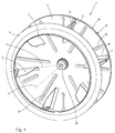
- eine perspektivische Vorderansicht eines Ventilatorrads, bei dem ein erstes Trägermittel als scheibenförmige Ronde und ein zweites Trägermittel als Ring jeweils koaxial zu einer Rotationsachse ausgebildet sind, wobei dem ersten Trägermittel eine koaxial zur Rotationsachse ausgebildete Stützscheibe zugeordnet ist und wobei zwischen den Trägermitteln in radialer Richtung ausgerichtete Schaufeln angeordnet sind,
- Figur 2
- eine perspektivische Schnittdarstellung des Ventilatorrads gemäß der
Figur 1 , - Figur 3
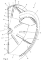
- eine seitliche Schnittdarstellung des Ventilatorrads gemäß der
Figur 1 , und - Figur 4
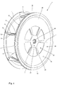
- eine perspektivische Rückansicht des Ventilatorrads gemäß der
Figur 1 . - Ein in den
Figuren 1 bis 4 in unterschiedlichen Ansichten dargestelltes Ventilatorrad 1 ist zur Förderung eines gasförmigen Fluids, insbesondere Luft, vorgesehen und kann beispielhaft in einem nicht dargestellten Backofen eingesetzt werden, wo es von einem nicht dargestellten Antriebsmotor in eine Rotationsbewegung um eine Rotationsachse 2 versetzt wird, um eine Umwälzung des im Backofen befindlichen Luftvolumens zu bewirken. - Das Ventilatorrad 1 weist exemplarisch ein als scheibenförmige Ronde 3 koaxial zur Rotationsachse 2 ausgebildetes erstes Trägermittel sowie ein als Ring 4 koaxial zur Rotationsachse 2 ausgebildetes zweites Trägermittel auf, die längs der Rotationsachse 2 beabstandet und koaxial zueinander angeordnet sind. Beispielhaft ist der Ring 4 bezogen auf die Rotationsachse 2 als Rotationskörper mit einem J-förmigen Profil ausgebildet und bildet eine Einströmdüse für einen Hauptfluidstrom, der bei einer Rotation des Ventilatorrads 1 um die Rotationsachse 2 in radialer Richtung nach außen zwischen den beiden Trägermitteln 3 und 4 gefördert wird.
- Zwischen der Ronde 3 und dem Ring 4 sind bezüglich der Rotationsachse 2 mehrere in vorgebbarer, insbesondere konstanter, Winkelteilung angeordnete Schaufeln 5 vorgesehen, deren größte Oberfläche 6 sich zwischen der Ronde 3 und dem Ring 4 erstreckt. Rein exemplarisch ist vorgesehen, dass die größte Oberfläche 6 eben ausgebildet ist und in einer nicht näher dargestellten Ebene angeordnet ist, die von der Rotationsachse 2 und einer quer zur Rotationsachse 2 in radialer Richtung erstreckten Radiallinie 7 begrenzt ist. Ferner ist rein exemplarisch vorgesehen, dass an der größten Oberfläche 6 ein Vorsprung 8 ausgebildet ist, dessen längste Kante 9 einen spitzen Winkel 10 mit der Rotationsachse 2 einnimmt, wie dies in der Darstellung der
Figur 3 angedeutet ist. Ferner ist beispielhaft vorgesehen, dass jede Schaufel 5 sowohl an einem der Ronde 3 zugewandten axialen Endbereich 11 als auch an einem dem Ring 4 zugewandten axialen Endbereich 12 eine quer zur größten Oberfläche 6 ausgerichtete Lasche 15, 16 aufweist, mit der die Schaufel 5 flächig, insbesondere stoffschlüssig, an der Ronde 3 bzw. am Ring 4 festgelegt ist. - Ferner ist rein exemplarisch vorgesehen, dass die längste Kante 9 des Vorsprungs 8 zumindest im Wesentlichen parallel zu einer Verbindungslinie 17 zwischen einer kreisförmigen Außenkante 18 der Ronde 3 und einer kreisförmigen Innenkante 19 des Rings 4 ausgerichtet ist.
- Der Ronde 3 ist eine koaxial zur Rotationsachse 2 ausgebildete Stützscheibe 20 zugeordnet, die mit der Ronde 3 einen Ringspalt 21 ausbildet. Rein exemplarisch ist die Stützscheibe 20 als Rotationskörper bezüglich der Rotationsachse 2 ausgebildet und mit mehreren Einlassöffnungen 22 versehen, die beispielhaft in gleicher Winkelteilung zur Rotationsachse 2 angeordnet sind. Dabei kann vorgesehen sein, dass sämtliche Einlassöffnungen 22 eine identische Querschnittgeometrie aufweisen und somit kongruent ausgebildet sind. Die Einlassöffnungen 22 sind exemplarisch derart an der Stützscheibe 20 angeordnet, dass zwischen den Einlassöffnungen 22 jeweils Radialspeichen 23 ausgebildet sind, die die Einlassöffnungen 22 in Umfangsrichtung begrenzen und die einen kreisringförmigen Innenbereich 24 der Stützscheibe 20 mit einem kreisringförmigen Außenbereich 25 der Stützscheibe 20 verbinden. Der Innenbereich der Stützscheibe ist mit einer Nabenanordnung 26 kraftübertragend verbunden, die ihrerseits mit der Ronde 3 kraftübertragend verbunden ist. Die Nabenanordnung 26 ist beispielhaft als Wellenkupplung ausgebildet, die für eine drehfeste Anbringung des Ventilatorrads 1 auf einer nicht dargestellten Antriebswelle eingerichtet ist.
- Rein exemplarisch sind an der Ronde 3, bei der es sich um einen stanzgeprägten Blechzuschnitt handeln kann, mehrere der Stützscheibe 20 zugewandte Vorsprünge 27 und 28 ausgebildet, die beispielhaft in der Art von Sicken verwirklicht sind. Bei den Vorsprüngen 27 handelt es sich um Leitvorsprünge, die sich nahezu über den gesamten Durchmesser der Ronde 3 in radialer Richtung erstrecken und die derart angeordnet sind, dass sie auf den Radialspeichen 23 und dem sich daran anschließenden Außenbereich 25 der Stützscheibe 20 aufliegen. Hingegen sind die Vorsprünge 28 als Stützvorsprünge ausgebildet, die beispielhaft nur auf dem Außenbereich 25 der Stützscheibe 20 aufliegen. Sowohl die Leitvorsprünge 27 als auch die Stützvorsprünge 28 weisen der Stützscheibe 20 zugewandte Stirnseiten 29 auf, die an einer der Ronde 3 zugewandten Oberfläche 30 der Stützscheibe 20 flächig anliegen und dort beispielsweise stoffschlüssig, insbesondere durch Kleben oder Schweißen, festgelegt sind. Damit bestimmen die Leitvorsprünge 27 und die Stützvorsprünge 28 den Abstand 31 zwischen der Ronde 3 und der Stützscheibe 20 und damit auch das Raumvolumen des Ringspalts 21. Dabei ist der Abstand 31 erheblich kleiner als ein Abstand 34 zwischen der Ronde 3 und dem Ring 4 gewählt, so dass bei einer Rotation des Ventilatorrads 1 um die Rotationsachse 2 ein von den Schaufeln 5 hervorgerufener (Haupt-)Fluidstrom, der durch den Ring 4 in axialer Richtung eintritt und in radialer Richtung zwischen Ronde 3 und Ring 4 nach außen austritt, erheblich größer als ein (Neben-)Fluidstrom durch den Ringspalt 21 ist, der durch die Einlassöffnungen 22 in axialer Richtung eintritt und in radialer Richtung nach außen zwischen der Ronde 3 und der Stützscheibe 20 austritt.
- Rein exemplarisch sind sowohl die Leitvorsprünge 27 als auch die Stützvorsprünge 28 mit einer jeweiligen Haupterstreckung entlang von nicht näher dargestellten Radiallinien ausgerichtet, die ausgehend von der Rotationsachse 2 in radialer Richtung nach außen verlaufen.
- Wie aus der Darstellung der
Figuren 2 und4 entnommen werden kann, weist die Stützscheibe 20 in einem radial außenliegenden Bereich einen zirkular umlaufenden Vorsprung 32 auf, der sich axial in einer von der Ronde 3 wegweisenden Richtung erstreckt und der als, exemplarisch dreiecksförmig profilierte, Sicke zur Stabilisierung der Stützscheibe 20 vorgesehen ist. Beispielhaft wird durch den Vorsprung 32 bei Betrachtung der Rückseite 33 des Ventilatorrads 1 eine konkave Vertiefung gebildet, während die der Ronde 3 zugewandte Oberfläche 30 der Stützscheibe 20 mit Ausnahme des Vorsprungs 32 rein exemplarisch eben ausgebildet ist. - Die Nabenanordnung 26 ermöglicht eine drehfeste Festlegung des Ventilatorrads 1 an einer nicht dargestellten Antriebswelle eines Motors, insbesondere eines Elektromotors. Vorzugsweise wird das Ventilatorrad 1 derart auf der Antriebswelle angeordnet, dass die Stützscheibe 20 dem Motor zugewandte ist, während der Ring 4 den Motor abgewandt ist. Hierdurch kann bei einer Rotation des Ventilatorrads 1 um die Rotationsachse 2 zusätzlich zu dem (Haupt-)Fluidstrom durch den Ring 4 ein (Neben-)Fluidstrom durch den Ringspalt 21 bewirkt werden, wobei dieser (Neben-)Fluidstrom beispielsweise erwärmte Luft aus der Umgebung des Motors abführen kann und dort damit zur Kühlung des Motors beiträgt.
Claims (12)
- Ventilatorrad zur Förderung eines gasförmigen Fluids, mit mehreren Schaufeln (5), die in vorgebbarer Winkelteilung in einem ringförmigen Raumvolumen um eine Rotationsachse (2) angeordnet sind und die mit ihren axialen, einander entgegengesetzten Endbereichen (11, 12) jeweils an Trägermitteln (3, 4) festgelegt sind, wobei ein erstes Trägermittel (3) als scheibenförmige Ronde koaxial zur Rotationsachse (2) ausgebildet ist und eine Nabenanordnung (26) umfasst und wobei ein zweites Trägermittel (4) als Ring koaxial zur Rotationsachse (2) ausgebildet ist, dadurch gekennzeichnet, dass beabstandet zum ersten Trägermittel (3) eine koaxial zur Rotationsachse (2) ausgebildete Stützscheibe (20) angeordnet ist, die mit dem ersten Trägermittel (3) einen Ringspalt (21) ausbildet und dass die Stützscheibe (20) von wenigstens einer Einlassöffnung (22) durchsetzt ist, die einen radial nach außen gerichteten Fluidstrom im Ringspalt (21) ermöglicht.
- Ventilatorrad nach Anspruch 1, dadurch gekennzeichnet, dass die Stützscheibe (20) mit der Nabenanordnung (26) verbunden ist.
- Ventilatorrad nach Anspruch 1 oder 2, dadurch gekennzeichnet, dass die Stützscheibe (20) unmittelbar mit dem ersten Trägermittel (3) verbunden ist.
- Ventilatorrad nach Anspruch 1, 2 oder 3, dadurch gekennzeichnet, dass an der Stützscheibe (20) und/oder am ersten Trägermittel (3) jeweils in axialer Richtung in den Ringspalt (21) erstreckte Vorsprünge (27, 28), insbesondere Sicken, ausgebildet sind, die an einer gegenüberliegenden Oberfläche (30) der Stützscheibe (20) oder des ersten Trägermittels (3) festgelegt sind.
- Ventilatorrad nach Anspruch 4, dadurch gekennzeichnet, dass die Vorsprünge (27, 28) eine in radialer Richtung ausgebildete Haupterstreckung aufweisen.
- Ventilatorrad nach einem der vorhergehenden Ansprüche, dadurch gekennzeichnet, dass die Stützscheibe (20) von mehreren, in gleicher Winkelteilung zur Rotationsachse (2) angeordneten, insbesondere kongruent ausgebildeten, Einlassöffnungen (22) durchsetzt ist, zwischen denen Radialspeichen (23) von der Nabenanordnung (26) zu einem radial außenliegenden Ringbereich (25) der Stützscheibe (20) erstreckt sind.
- Ventilatorrad nach Anspruch 6, dadurch gekennzeichnet, dass Leitvorsprünge (27), insbesondere Sicken, des ersten Trägermittels (3) entlang der Radialspeichen (23) bis zum radial außenliegenden Ringbereich (25), insbesondere bis zu einem Maximaldurchmesser des Ringbereichs (25), erstreckt sind.
- Ventilatorrad nach Anspruch 7, dadurch gekennzeichnet, dass an dem ersten Trägermittel (3) und/oder an der Stützscheibe (20) jeweils zwischen benachbarten Leitvorsprüngen (27) angeordnete, in radialer Richtung über den radial außenliegenden Ringbereich (25) erstreckte Stützvorsprünge (28), insbesondere Sicken, ausgebildet sind, die an einer gegenüberliegenden Oberfläche (30) der Stützscheibe (20) oder des ersten Trägermittels (3) festgelegt sind.
- Ventilatorrad nach einem der vorhergehenden Ansprüche, dadurch gekennzeichnet, dass die Stützscheibe (20) in einem radial außenliegenden Bereich einen zumindest bereichsweise zirkular umlaufenden Vorsprung (32) aufweist, der in einer dem Ringspalt (21) entgegengesetzten Axialrichtung erstreckt ist.
- Ventilatorrad nach einem der vorhergehenden Ansprüche, dadurch gekennzeichnet, dass an den Schaufeln (5) in einem radial außenliegenden Bereich jeweils ein Vorsprung (8) ausgebildet ist, dessen längste Kante (9) mit der Rotationsachse (2) einen spitzen Winkel (10) einnimmt.
- Ventilatorrad nach Anspruch 10, dadurch gekennzeichnet, dass die längste Kante (9) des Vorsprungs (8) an der Schaufel (5), insbesondere zumindest im Wesentlichen, parallel zu einer Verbindungslinie (17) zwischen einer Außenkante (18) des als scheibenförmige Ronde ausgebildeten ersten Trägermittels (3) und einer Innenkante des als Ring ausgebildeten zweiten Trägermittels (4) ausgerichtet ist.
- Gebläseanordnung mit einem Antriebsmotor, der eine drehbar an einem Motorgehäuse gelagerte Antriebswelle umfasst, sowie mit einem Ventilatorrad (1) nach einem der vorhergehenden Ansprüche, das mit der Nabenanordnung (26) derart drehfest an der Antriebswelle festgelegt ist, dass die Stützscheibe (20) benachbart zum Motorgehäuse angeordnet ist, so dass bei einer Rotationsbewegung des Ventilatorrads (1) um die Rotationsachse (2) ein Fluidstrom vom Motorgehäuse in Richtung der Stützscheibe (20) bewirkt wird.
Priority Applications (1)
| Application Number | Priority Date | Filing Date | Title |
|---|---|---|---|
| EP16153807.9A EP3203084B1 (de) | 2016-02-02 | 2016-02-02 | Ventilatorrad und gebläseanordnung |
Applications Claiming Priority (1)
| Application Number | Priority Date | Filing Date | Title |
|---|---|---|---|
| EP16153807.9A EP3203084B1 (de) | 2016-02-02 | 2016-02-02 | Ventilatorrad und gebläseanordnung |
Publications (2)
| Publication Number | Publication Date |
|---|---|
| EP3203084A1 true EP3203084A1 (de) | 2017-08-09 |
| EP3203084B1 EP3203084B1 (de) | 2020-07-15 |
Family
ID=55299323
Family Applications (1)
| Application Number | Title | Priority Date | Filing Date |
|---|---|---|---|
| EP16153807.9A Active EP3203084B1 (de) | 2016-02-02 | 2016-02-02 | Ventilatorrad und gebläseanordnung |
Country Status (1)
| Country | Link |
|---|---|
| EP (1) | EP3203084B1 (de) |
Cited By (1)
| Publication number | Priority date | Publication date | Assignee | Title |
|---|---|---|---|---|
| EP4481202A1 (de) * | 2023-06-21 | 2024-12-25 | ebm-papst Mulfingen GmbH & Co. KG | Laufrad für radiallüfter |
Citations (5)
| Publication number | Priority date | Publication date | Assignee | Title |
|---|---|---|---|---|
| US3414188A (en) * | 1966-11-25 | 1968-12-03 | American Radiator & Standard | Fan having hollow blades |
| DE1628336A1 (de) | 1965-09-08 | 1970-05-21 | Nordisk Ventilator | Zentrifugalgeblaese mit Trommellaufrad |
| DE3310376A1 (de) * | 1983-03-22 | 1984-09-27 | Ebm Elektrobau Mulfingen Gmbh & Co, 7119 Mulfingen | Radialgeblaese mit spiralgehaeuse |
| DE102008048433A1 (de) * | 2008-09-23 | 2010-03-25 | Daimler Ag | Radialgebläse |
| EP2846046A1 (de) * | 2013-09-10 | 2015-03-11 | Punker GmbH | Ventilatorrad |
-
2016
- 2016-02-02 EP EP16153807.9A patent/EP3203084B1/de active Active
Patent Citations (5)
| Publication number | Priority date | Publication date | Assignee | Title |
|---|---|---|---|---|
| DE1628336A1 (de) | 1965-09-08 | 1970-05-21 | Nordisk Ventilator | Zentrifugalgeblaese mit Trommellaufrad |
| US3414188A (en) * | 1966-11-25 | 1968-12-03 | American Radiator & Standard | Fan having hollow blades |
| DE3310376A1 (de) * | 1983-03-22 | 1984-09-27 | Ebm Elektrobau Mulfingen Gmbh & Co, 7119 Mulfingen | Radialgeblaese mit spiralgehaeuse |
| DE102008048433A1 (de) * | 2008-09-23 | 2010-03-25 | Daimler Ag | Radialgebläse |
| EP2846046A1 (de) * | 2013-09-10 | 2015-03-11 | Punker GmbH | Ventilatorrad |
Cited By (1)
| Publication number | Priority date | Publication date | Assignee | Title |
|---|---|---|---|---|
| EP4481202A1 (de) * | 2023-06-21 | 2024-12-25 | ebm-papst Mulfingen GmbH & Co. KG | Laufrad für radiallüfter |
Also Published As
| Publication number | Publication date |
|---|---|
| EP3203084B1 (de) | 2020-07-15 |
Similar Documents
| Publication | Publication Date | Title |
|---|---|---|
| EP2846046B1 (de) | Ventilatorrad | |
| EP1934483B1 (de) | Ventilatorrad | |
| EP2122181B1 (de) | Lüfterrad, system und getriebebaureihe | |
| DE102008010912B4 (de) | Lüfterrad, System und Getriebebaureihe | |
| EP2994615B1 (de) | Rotor für eine thermische strömungsmaschine | |
| EP2826958A1 (de) | Rotor für eine thermische Strömungsmaschine | |
| WO2016046036A1 (de) | Radialverdichterlaufrad und zugehöriger radialverdichter | |
| DE102008053144A1 (de) | Lüfteranordnung und Gargerät | |
| DE102010035284A1 (de) | Laufrad | |
| DE102015113393B4 (de) | Abgasturbolader | |
| EP3203084A1 (de) | Ventilatorrad und gebläseanordnung | |
| EP3949090B1 (de) | Lüftersystem mit einem elektromotor | |
| EP2478226B1 (de) | Lüfter für eine brennkraftmaschine | |
| DE19847632B4 (de) | Verfahren zur Herstellung eines Ringlüfters | |
| DE102007037012B4 (de) | Gebläseeinheit und handgetragenes Blasgerät | |
| EP3892862B1 (de) | Lüfterrad | |
| DE19611186C1 (de) | Belagfedersegmente mit Überlappung | |
| DE102014210020A1 (de) | Verbesserter Rotor für Zentrifugalgebläse, insbesondere für die Zwangs-Luftzirkulation in Umluftöfen | |
| DE10111292A1 (de) | Lüfteranordnung für eine elektrische Maschine | |
| DE102016107186B3 (de) | Rotor für einen Elektromotor, insbesondere für ein Fahrzeugheizgerät | |
| DE102013018033B4 (de) | Bandförmige lauf- oder leitschaufelanordnung und verfahren zur herstellung | |
| DE102023004754A1 (de) | Lüfterrad und Elektromotor mit Lüfterrad | |
| DE202012002909U1 (de) | Lüfter | |
| DE102010020574A1 (de) | Strömungsführende Einrichtung | |
| EP3219913A1 (de) | Rotor mit kühlluftführung |
Legal Events
| Date | Code | Title | Description |
|---|---|---|---|
| PUAI | Public reference made under article 153(3) epc to a published international application that has entered the european phase |
Free format text: ORIGINAL CODE: 0009012 |
|
| STAA | Information on the status of an ep patent application or granted ep patent |
Free format text: STATUS: THE APPLICATION HAS BEEN PUBLISHED |
|
| AK | Designated contracting states |
Kind code of ref document: A1 Designated state(s): AL AT BE BG CH CY CZ DE DK EE ES FI FR GB GR HR HU IE IS IT LI LT LU LV MC MK MT NL NO PL PT RO RS SE SI SK SM TR |
|
| AX | Request for extension of the european patent |
Extension state: BA ME |
|
| STAA | Information on the status of an ep patent application or granted ep patent |
Free format text: STATUS: REQUEST FOR EXAMINATION WAS MADE |
|
| 17P | Request for examination filed |
Effective date: 20180209 |
|
| RBV | Designated contracting states (corrected) |
Designated state(s): AL AT BE BG CH CY CZ DE DK EE ES FI FR GB GR HR HU IE IS IT LI LT LU LV MC MK MT NL NO PL PT RO RS SE SI SK SM TR |
|
| GRAP | Despatch of communication of intention to grant a patent |
Free format text: ORIGINAL CODE: EPIDOSNIGR1 |
|
| STAA | Information on the status of an ep patent application or granted ep patent |
Free format text: STATUS: GRANT OF PATENT IS INTENDED |
|
| INTG | Intention to grant announced |
Effective date: 20200210 |
|
| GRAS | Grant fee paid |
Free format text: ORIGINAL CODE: EPIDOSNIGR3 |
|
| GRAA | (expected) grant |
Free format text: ORIGINAL CODE: 0009210 |
|
| STAA | Information on the status of an ep patent application or granted ep patent |
Free format text: STATUS: THE PATENT HAS BEEN GRANTED |
|
| AK | Designated contracting states |
Kind code of ref document: B1 Designated state(s): AL AT BE BG CH CY CZ DE DK EE ES FI FR GB GR HR HU IE IS IT LI LT LU LV MC MK MT NL NO PL PT RO RS SE SI SK SM TR |
|
| REG | Reference to a national code |
Ref country code: GB Ref legal event code: FG4D Free format text: NOT ENGLISH Ref country code: CH Ref legal event code: EP |
|
| REG | Reference to a national code |
Ref country code: IE Ref legal event code: FG4D Free format text: LANGUAGE OF EP DOCUMENT: GERMAN |
|
| REG | Reference to a national code |
Ref country code: DE Ref legal event code: R096 Ref document number: 502016010487 Country of ref document: DE |
|
| REG | Reference to a national code |
Ref country code: AT Ref legal event code: REF Ref document number: 1291331 Country of ref document: AT Kind code of ref document: T Effective date: 20200815 |
|
| REG | Reference to a national code |
Ref country code: LT Ref legal event code: MG4D |
|
| REG | Reference to a national code |
Ref country code: NL Ref legal event code: MP Effective date: 20200715 |
|
| PG25 | Lapsed in a contracting state [announced via postgrant information from national office to epo] |
Ref country code: NO Free format text: LAPSE BECAUSE OF FAILURE TO SUBMIT A TRANSLATION OF THE DESCRIPTION OR TO PAY THE FEE WITHIN THE PRESCRIBED TIME-LIMIT Effective date: 20201015 Ref country code: GR Free format text: LAPSE BECAUSE OF FAILURE TO SUBMIT A TRANSLATION OF THE DESCRIPTION OR TO PAY THE FEE WITHIN THE PRESCRIBED TIME-LIMIT Effective date: 20201016 Ref country code: FI Free format text: LAPSE BECAUSE OF FAILURE TO SUBMIT A TRANSLATION OF THE DESCRIPTION OR TO PAY THE FEE WITHIN THE PRESCRIBED TIME-LIMIT Effective date: 20200715 Ref country code: SE Free format text: LAPSE BECAUSE OF FAILURE TO SUBMIT A TRANSLATION OF THE DESCRIPTION OR TO PAY THE FEE WITHIN THE PRESCRIBED TIME-LIMIT Effective date: 20200715 Ref country code: PT Free format text: LAPSE BECAUSE OF FAILURE TO SUBMIT A TRANSLATION OF THE DESCRIPTION OR TO PAY THE FEE WITHIN THE PRESCRIBED TIME-LIMIT Effective date: 20201116 Ref country code: HR Free format text: LAPSE BECAUSE OF FAILURE TO SUBMIT A TRANSLATION OF THE DESCRIPTION OR TO PAY THE FEE WITHIN THE PRESCRIBED TIME-LIMIT Effective date: 20200715 Ref country code: LT Free format text: LAPSE BECAUSE OF FAILURE TO SUBMIT A TRANSLATION OF THE DESCRIPTION OR TO PAY THE FEE WITHIN THE PRESCRIBED TIME-LIMIT Effective date: 20200715 Ref country code: BG Free format text: LAPSE BECAUSE OF FAILURE TO SUBMIT A TRANSLATION OF THE DESCRIPTION OR TO PAY THE FEE WITHIN THE PRESCRIBED TIME-LIMIT Effective date: 20201015 Ref country code: ES Free format text: LAPSE BECAUSE OF FAILURE TO SUBMIT A TRANSLATION OF THE DESCRIPTION OR TO PAY THE FEE WITHIN THE PRESCRIBED TIME-LIMIT Effective date: 20200715 |
|
| PG25 | Lapsed in a contracting state [announced via postgrant information from national office to epo] |
Ref country code: IS Free format text: LAPSE BECAUSE OF FAILURE TO SUBMIT A TRANSLATION OF THE DESCRIPTION OR TO PAY THE FEE WITHIN THE PRESCRIBED TIME-LIMIT Effective date: 20201115 Ref country code: PL Free format text: LAPSE BECAUSE OF FAILURE TO SUBMIT A TRANSLATION OF THE DESCRIPTION OR TO PAY THE FEE WITHIN THE PRESCRIBED TIME-LIMIT Effective date: 20200715 Ref country code: LV Free format text: LAPSE BECAUSE OF FAILURE TO SUBMIT A TRANSLATION OF THE DESCRIPTION OR TO PAY THE FEE WITHIN THE PRESCRIBED TIME-LIMIT Effective date: 20200715 Ref country code: RS Free format text: LAPSE BECAUSE OF FAILURE TO SUBMIT A TRANSLATION OF THE DESCRIPTION OR TO PAY THE FEE WITHIN THE PRESCRIBED TIME-LIMIT Effective date: 20200715 |
|
| PG25 | Lapsed in a contracting state [announced via postgrant information from national office to epo] |
Ref country code: NL Free format text: LAPSE BECAUSE OF FAILURE TO SUBMIT A TRANSLATION OF THE DESCRIPTION OR TO PAY THE FEE WITHIN THE PRESCRIBED TIME-LIMIT Effective date: 20200715 |
|
| REG | Reference to a national code |
Ref country code: DE Ref legal event code: R097 Ref document number: 502016010487 Country of ref document: DE |
|
| PG25 | Lapsed in a contracting state [announced via postgrant information from national office to epo] |
Ref country code: SM Free format text: LAPSE BECAUSE OF FAILURE TO SUBMIT A TRANSLATION OF THE DESCRIPTION OR TO PAY THE FEE WITHIN THE PRESCRIBED TIME-LIMIT Effective date: 20200715 Ref country code: RO Free format text: LAPSE BECAUSE OF FAILURE TO SUBMIT A TRANSLATION OF THE DESCRIPTION OR TO PAY THE FEE WITHIN THE PRESCRIBED TIME-LIMIT Effective date: 20200715 Ref country code: EE Free format text: LAPSE BECAUSE OF FAILURE TO SUBMIT A TRANSLATION OF THE DESCRIPTION OR TO PAY THE FEE WITHIN THE PRESCRIBED TIME-LIMIT Effective date: 20200715 Ref country code: DK Free format text: LAPSE BECAUSE OF FAILURE TO SUBMIT A TRANSLATION OF THE DESCRIPTION OR TO PAY THE FEE WITHIN THE PRESCRIBED TIME-LIMIT Effective date: 20200715 Ref country code: CZ Free format text: LAPSE BECAUSE OF FAILURE TO SUBMIT A TRANSLATION OF THE DESCRIPTION OR TO PAY THE FEE WITHIN THE PRESCRIBED TIME-LIMIT Effective date: 20200715 |
|
| REG | Reference to a national code |
Ref country code: DE Ref legal event code: R082 Ref document number: 502016010487 Country of ref document: DE Representative=s name: PATENTANWAELTE MAGENBAUER & KOLLEGEN PARTNERSC, DE Ref country code: DE Ref legal event code: R081 Ref document number: 502016010487 Country of ref document: DE Owner name: RATIONAL AKTIENGESELLSCHAFT, DE Free format text: FORMER OWNER: PUNKER GMBH, 24340 ECKERNFOERDE, DE Ref country code: DE Ref legal event code: R081 Ref document number: 502016010487 Country of ref document: DE Owner name: PUNKER GMBH, DE Free format text: FORMER OWNER: PUNKER GMBH, 24340 ECKERNFOERDE, DE |
|
| PLBE | No opposition filed within time limit |
Free format text: ORIGINAL CODE: 0009261 |
|
| STAA | Information on the status of an ep patent application or granted ep patent |
Free format text: STATUS: NO OPPOSITION FILED WITHIN TIME LIMIT |
|
| PG25 | Lapsed in a contracting state [announced via postgrant information from national office to epo] |
Ref country code: AL Free format text: LAPSE BECAUSE OF FAILURE TO SUBMIT A TRANSLATION OF THE DESCRIPTION OR TO PAY THE FEE WITHIN THE PRESCRIBED TIME-LIMIT Effective date: 20200715 |
|
| 26N | No opposition filed |
Effective date: 20210416 |
|
| PG25 | Lapsed in a contracting state [announced via postgrant information from national office to epo] |
Ref country code: SK Free format text: LAPSE BECAUSE OF FAILURE TO SUBMIT A TRANSLATION OF THE DESCRIPTION OR TO PAY THE FEE WITHIN THE PRESCRIBED TIME-LIMIT Effective date: 20200715 |
|
| PG25 | Lapsed in a contracting state [announced via postgrant information from national office to epo] |
Ref country code: SI Free format text: LAPSE BECAUSE OF FAILURE TO SUBMIT A TRANSLATION OF THE DESCRIPTION OR TO PAY THE FEE WITHIN THE PRESCRIBED TIME-LIMIT Effective date: 20200715 |
|
| PG25 | Lapsed in a contracting state [announced via postgrant information from national office to epo] |
Ref country code: MC Free format text: LAPSE BECAUSE OF FAILURE TO SUBMIT A TRANSLATION OF THE DESCRIPTION OR TO PAY THE FEE WITHIN THE PRESCRIBED TIME-LIMIT Effective date: 20200715 |
|
| GBPC | Gb: european patent ceased through non-payment of renewal fee |
Effective date: 20210202 |
|
| REG | Reference to a national code |
Ref country code: BE Ref legal event code: MM Effective date: 20210228 |
|
| PG25 | Lapsed in a contracting state [announced via postgrant information from national office to epo] |
Ref country code: LU Free format text: LAPSE BECAUSE OF NON-PAYMENT OF DUE FEES Effective date: 20210202 Ref country code: LI Free format text: LAPSE BECAUSE OF NON-PAYMENT OF DUE FEES Effective date: 20210228 Ref country code: CH Free format text: LAPSE BECAUSE OF NON-PAYMENT OF DUE FEES Effective date: 20210228 |
|
| PG25 | Lapsed in a contracting state [announced via postgrant information from national office to epo] |
Ref country code: IE Free format text: LAPSE BECAUSE OF NON-PAYMENT OF DUE FEES Effective date: 20210202 Ref country code: FR Free format text: LAPSE BECAUSE OF NON-PAYMENT OF DUE FEES Effective date: 20210228 Ref country code: GB Free format text: LAPSE BECAUSE OF NON-PAYMENT OF DUE FEES Effective date: 20210202 |
|
| REG | Reference to a national code |
Ref country code: AT Ref legal event code: MM01 Ref document number: 1291331 Country of ref document: AT Kind code of ref document: T Effective date: 20210202 |
|
| PG25 | Lapsed in a contracting state [announced via postgrant information from national office to epo] |
Ref country code: AT Free format text: LAPSE BECAUSE OF NON-PAYMENT OF DUE FEES Effective date: 20210202 |
|
| PG25 | Lapsed in a contracting state [announced via postgrant information from national office to epo] |
Ref country code: BE Free format text: LAPSE BECAUSE OF NON-PAYMENT OF DUE FEES Effective date: 20210228 |
|
| PG25 | Lapsed in a contracting state [announced via postgrant information from national office to epo] |
Ref country code: HU Free format text: LAPSE BECAUSE OF FAILURE TO SUBMIT A TRANSLATION OF THE DESCRIPTION OR TO PAY THE FEE WITHIN THE PRESCRIBED TIME-LIMIT; INVALID AB INITIO Effective date: 20160202 |
|
| P01 | Opt-out of the competence of the unified patent court (upc) registered |
Effective date: 20230523 |
|
| PG25 | Lapsed in a contracting state [announced via postgrant information from national office to epo] |
Ref country code: CY Free format text: LAPSE BECAUSE OF FAILURE TO SUBMIT A TRANSLATION OF THE DESCRIPTION OR TO PAY THE FEE WITHIN THE PRESCRIBED TIME-LIMIT Effective date: 20200715 |
|
| PG25 | Lapsed in a contracting state [announced via postgrant information from national office to epo] |
Ref country code: MK Free format text: LAPSE BECAUSE OF FAILURE TO SUBMIT A TRANSLATION OF THE DESCRIPTION OR TO PAY THE FEE WITHIN THE PRESCRIBED TIME-LIMIT Effective date: 20200715 |
|
| PG25 | Lapsed in a contracting state [announced via postgrant information from national office to epo] |
Ref country code: MT Free format text: LAPSE BECAUSE OF FAILURE TO SUBMIT A TRANSLATION OF THE DESCRIPTION OR TO PAY THE FEE WITHIN THE PRESCRIBED TIME-LIMIT Effective date: 20200715 |
|
| PGFP | Annual fee paid to national office [announced via postgrant information from national office to epo] |
Ref country code: DE Payment date: 20250218 Year of fee payment: 10 |
|
| PGFP | Annual fee paid to national office [announced via postgrant information from national office to epo] |
Ref country code: IT Payment date: 20250228 Year of fee payment: 10 |
|
| PG25 | Lapsed in a contracting state [announced via postgrant information from national office to epo] |
Ref country code: TR Free format text: LAPSE BECAUSE OF FAILURE TO SUBMIT A TRANSLATION OF THE DESCRIPTION OR TO PAY THE FEE WITHIN THE PRESCRIBED TIME-LIMIT Effective date: 20200715 |