EP3203071B1 - Dispositif pneumatique miniature - Google Patents
Dispositif pneumatique miniature Download PDFInfo
- Publication number
- EP3203071B1 EP3203071B1 EP16207271.4A EP16207271A EP3203071B1 EP 3203071 B1 EP3203071 B1 EP 3203071B1 EP 16207271 A EP16207271 A EP 16207271A EP 3203071 B1 EP3203071 B1 EP 3203071B1
- Authority
- EP
- European Patent Office
- Prior art keywords
- plate
- gas
- chamber
- pressure
- outlet
- Prior art date
- Legal status (The legal status is an assumption and is not a legal conclusion. Google has not performed a legal analysis and makes no representation as to the accuracy of the status listed.)
- Active
Links
- 239000000725 suspension Substances 0.000 claims description 137
- 230000003578 releasing effect Effects 0.000 claims description 132
- 239000012530 fluid Substances 0.000 claims description 64
- 238000004891 communication Methods 0.000 claims description 42
- 239000000919 ceramic Substances 0.000 claims description 38
- 230000000903 blocking effect Effects 0.000 claims description 4
- 229910001220 stainless steel Inorganic materials 0.000 claims description 3
- 239000010935 stainless steel Substances 0.000 claims description 3
- RYGMFSIKBFXOCR-UHFFFAOYSA-N Copper Chemical compound [Cu] RYGMFSIKBFXOCR-UHFFFAOYSA-N 0.000 claims description 2
- 229910052802 copper Inorganic materials 0.000 claims description 2
- 239000010949 copper Substances 0.000 claims description 2
- 239000007789 gas Substances 0.000 description 253
- 238000009413 insulation Methods 0.000 description 16
- 230000004044 response Effects 0.000 description 13
- 239000003570 air Substances 0.000 description 12
- 230000009471 action Effects 0.000 description 8
- 230000002093 peripheral effect Effects 0.000 description 5
- 238000000034 method Methods 0.000 description 4
- 238000012360 testing method Methods 0.000 description 4
- 239000012080 ambient air Substances 0.000 description 3
- 230000005540 biological transmission Effects 0.000 description 3
- 230000003247 decreasing effect Effects 0.000 description 3
- 230000007547 defect Effects 0.000 description 3
- 238000006073 displacement reaction Methods 0.000 description 3
- 230000000694 effects Effects 0.000 description 3
- 238000003754 machining Methods 0.000 description 3
- 238000012986 modification Methods 0.000 description 3
- 230000004048 modification Effects 0.000 description 3
- 238000007789 sealing Methods 0.000 description 3
- 230000004308 accommodation Effects 0.000 description 2
- 238000002474 experimental method Methods 0.000 description 2
- 239000000463 material Substances 0.000 description 2
- 238000007639 printing Methods 0.000 description 2
- 230000008569 process Effects 0.000 description 2
- 239000000853 adhesive Substances 0.000 description 1
- 230000001070 adhesive effect Effects 0.000 description 1
- 230000004075 alteration Effects 0.000 description 1
- 239000004020 conductor Substances 0.000 description 1
- 230000002950 deficient Effects 0.000 description 1
- 238000005323 electroforming Methods 0.000 description 1
- 238000005516 engineering process Methods 0.000 description 1
- 238000005530 etching Methods 0.000 description 1
- 239000000945 filler Substances 0.000 description 1
- 239000011810 insulating material Substances 0.000 description 1
- 239000012528 membrane Substances 0.000 description 1
- 239000002184 metal Substances 0.000 description 1
- 229910052751 metal Inorganic materials 0.000 description 1
- 239000007769 metal material Substances 0.000 description 1
- 238000000206 photolithography Methods 0.000 description 1
- 238000005549 size reduction Methods 0.000 description 1
- 238000012546 transfer Methods 0.000 description 1
- 230000001960 triggered effect Effects 0.000 description 1
Images


Classifications
-
- F—MECHANICAL ENGINEERING; LIGHTING; HEATING; WEAPONS; BLASTING
- F04—POSITIVE - DISPLACEMENT MACHINES FOR LIQUIDS; PUMPS FOR LIQUIDS OR ELASTIC FLUIDS
- F04B—POSITIVE-DISPLACEMENT MACHINES FOR LIQUIDS; PUMPS
- F04B45/00—Pumps or pumping installations having flexible working members and specially adapted for elastic fluids
- F04B45/04—Pumps or pumping installations having flexible working members and specially adapted for elastic fluids having plate-like flexible members, e.g. diaphragms
- F04B45/047—Pumps having electric drive
-
- F—MECHANICAL ENGINEERING; LIGHTING; HEATING; WEAPONS; BLASTING
- F04—POSITIVE - DISPLACEMENT MACHINES FOR LIQUIDS; PUMPS FOR LIQUIDS OR ELASTIC FLUIDS
- F04B—POSITIVE-DISPLACEMENT MACHINES FOR LIQUIDS; PUMPS
- F04B53/00—Component parts, details or accessories not provided for in, or of interest apart from, groups F04B1/00 - F04B23/00 or F04B39/00 - F04B47/00
- F04B53/001—Noise damping
-
- F—MECHANICAL ENGINEERING; LIGHTING; HEATING; WEAPONS; BLASTING
- F04—POSITIVE - DISPLACEMENT MACHINES FOR LIQUIDS; PUMPS FOR LIQUIDS OR ELASTIC FLUIDS
- F04B—POSITIVE-DISPLACEMENT MACHINES FOR LIQUIDS; PUMPS
- F04B53/00—Component parts, details or accessories not provided for in, or of interest apart from, groups F04B1/00 - F04B23/00 or F04B39/00 - F04B47/00
- F04B53/10—Valves; Arrangement of valves
-
- F—MECHANICAL ENGINEERING; LIGHTING; HEATING; WEAPONS; BLASTING
- F04—POSITIVE - DISPLACEMENT MACHINES FOR LIQUIDS; PUMPS FOR LIQUIDS OR ELASTIC FLUIDS
- F04B—POSITIVE-DISPLACEMENT MACHINES FOR LIQUIDS; PUMPS
- F04B53/00—Component parts, details or accessories not provided for in, or of interest apart from, groups F04B1/00 - F04B23/00 or F04B39/00 - F04B47/00
- F04B53/16—Casings; Cylinders; Cylinder liners or heads; Fluid connections
-
- F—MECHANICAL ENGINEERING; LIGHTING; HEATING; WEAPONS; BLASTING
- F15—FLUID-PRESSURE ACTUATORS; HYDRAULICS OR PNEUMATICS IN GENERAL
- F15B—SYSTEMS ACTING BY MEANS OF FLUIDS IN GENERAL; FLUID-PRESSURE ACTUATORS, e.g. SERVOMOTORS; DETAILS OF FLUID-PRESSURE SYSTEMS, NOT OTHERWISE PROVIDED FOR
- F15B13/00—Details of servomotor systems ; Valves for servomotor systems
- F15B13/02—Fluid distribution or supply devices characterised by their adaptation to the control of servomotors
-
- F—MECHANICAL ENGINEERING; LIGHTING; HEATING; WEAPONS; BLASTING
- F16—ENGINEERING ELEMENTS AND UNITS; GENERAL MEASURES FOR PRODUCING AND MAINTAINING EFFECTIVE FUNCTIONING OF MACHINES OR INSTALLATIONS; THERMAL INSULATION IN GENERAL
- F16K—VALVES; TAPS; COCKS; ACTUATING-FLOATS; DEVICES FOR VENTING OR AERATING
- F16K99/00—Subject matter not provided for in other groups of this subclass
- F16K99/0001—Microvalves
- F16K99/0003—Constructional types of microvalves; Details of the cutting-off member
- F16K99/0015—Diaphragm or membrane valves
-
- F—MECHANICAL ENGINEERING; LIGHTING; HEATING; WEAPONS; BLASTING
- F16—ENGINEERING ELEMENTS AND UNITS; GENERAL MEASURES FOR PRODUCING AND MAINTAINING EFFECTIVE FUNCTIONING OF MACHINES OR INSTALLATIONS; THERMAL INSULATION IN GENERAL
- F16K—VALVES; TAPS; COCKS; ACTUATING-FLOATS; DEVICES FOR VENTING OR AERATING
- F16K99/00—Subject matter not provided for in other groups of this subclass
- F16K99/0001—Microvalves
- F16K99/0034—Operating means specially adapted for microvalves
- F16K99/0042—Electric operating means therefor
- F16K99/0048—Electric operating means therefor using piezoelectric means
-
- F—MECHANICAL ENGINEERING; LIGHTING; HEATING; WEAPONS; BLASTING
- F04—POSITIVE - DISPLACEMENT MACHINES FOR LIQUIDS; PUMPS FOR LIQUIDS OR ELASTIC FLUIDS
- F04B—POSITIVE-DISPLACEMENT MACHINES FOR LIQUIDS; PUMPS
- F04B2203/00—Motor parameters
- F04B2203/04—Motor parameters of linear electric motors
- F04B2203/0402—Voltage
-
- F—MECHANICAL ENGINEERING; LIGHTING; HEATING; WEAPONS; BLASTING
- F04—POSITIVE - DISPLACEMENT MACHINES FOR LIQUIDS; PUMPS FOR LIQUIDS OR ELASTIC FLUIDS
- F04B—POSITIVE-DISPLACEMENT MACHINES FOR LIQUIDS; PUMPS
- F04B2203/00—Motor parameters
- F04B2203/04—Motor parameters of linear electric motors
- F04B2203/0404—Frequency of the electric current
-
- F—MECHANICAL ENGINEERING; LIGHTING; HEATING; WEAPONS; BLASTING
- F04—POSITIVE - DISPLACEMENT MACHINES FOR LIQUIDS; PUMPS FOR LIQUIDS OR ELASTIC FLUIDS
- F04B—POSITIVE-DISPLACEMENT MACHINES FOR LIQUIDS; PUMPS
- F04B2205/00—Fluid parameters
- F04B2205/05—Pressure after the pump outlet
-
- F—MECHANICAL ENGINEERING; LIGHTING; HEATING; WEAPONS; BLASTING
- F05—INDEXING SCHEMES RELATING TO ENGINES OR PUMPS IN VARIOUS SUBCLASSES OF CLASSES F01-F04
- F05B—INDEXING SCHEME RELATING TO WIND, SPRING, WEIGHT, INERTIA OR LIKE MOTORS, TO MACHINES OR ENGINES FOR LIQUIDS COVERED BY SUBCLASSES F03B, F03D AND F03G
- F05B2210/00—Working fluid
- F05B2210/10—Kind or type
- F05B2210/12—Kind or type gaseous, i.e. compressible
-
- F—MECHANICAL ENGINEERING; LIGHTING; HEATING; WEAPONS; BLASTING
- F05—INDEXING SCHEMES RELATING TO ENGINES OR PUMPS IN VARIOUS SUBCLASSES OF CLASSES F01-F04
- F05B—INDEXING SCHEME RELATING TO WIND, SPRING, WEIGHT, INERTIA OR LIKE MOTORS, TO MACHINES OR ENGINES FOR LIQUIDS COVERED BY SUBCLASSES F03B, F03D AND F03G
- F05B2260/00—Function
- F05B2260/60—Fluid transfer
-
- F—MECHANICAL ENGINEERING; LIGHTING; HEATING; WEAPONS; BLASTING
- F05—INDEXING SCHEMES RELATING TO ENGINES OR PUMPS IN VARIOUS SUBCLASSES OF CLASSES F01-F04
- F05B—INDEXING SCHEME RELATING TO WIND, SPRING, WEIGHT, INERTIA OR LIKE MOTORS, TO MACHINES OR ENGINES FOR LIQUIDS COVERED BY SUBCLASSES F03B, F03D AND F03G
- F05B2260/00—Function
- F05B2260/96—Preventing, counteracting or reducing vibration or noise
-
- F—MECHANICAL ENGINEERING; LIGHTING; HEATING; WEAPONS; BLASTING
- F16—ENGINEERING ELEMENTS AND UNITS; GENERAL MEASURES FOR PRODUCING AND MAINTAINING EFFECTIVE FUNCTIONING OF MACHINES OR INSTALLATIONS; THERMAL INSULATION IN GENERAL
- F16K—VALVES; TAPS; COCKS; ACTUATING-FLOATS; DEVICES FOR VENTING OR AERATING
- F16K99/00—Subject matter not provided for in other groups of this subclass
- F16K2099/0082—Microvalves adapted for a particular use
- F16K2099/0094—Micropumps
-
- Y—GENERAL TAGGING OF NEW TECHNOLOGICAL DEVELOPMENTS; GENERAL TAGGING OF CROSS-SECTIONAL TECHNOLOGIES SPANNING OVER SEVERAL SECTIONS OF THE IPC; TECHNICAL SUBJECTS COVERED BY FORMER USPC CROSS-REFERENCE ART COLLECTIONS [XRACs] AND DIGESTS
- Y10—TECHNICAL SUBJECTS COVERED BY FORMER USPC
- Y10S—TECHNICAL SUBJECTS COVERED BY FORMER USPC CROSS-REFERENCE ART COLLECTIONS [XRACs] AND DIGESTS
- Y10S417/00—Pumps
Definitions
- the present invention relates to a pneumatic device, and more particularly to a slim and silent miniature pneumatic device.
- fluid transportation devices used in many sectors such as pharmaceutical industries, computer techniques, printing industries or energy industries are developed toward elaboration and miniaturization.
- the fluid transportation devices are important components that are used in for example micro pumps, micro atomizers, printheads or industrial printers. Therefore, it is important to provide an improved structure of the fluid transportation device.
- CN 104234986 A discloses a miniature pneumatic power device which comprises a miniature air transmission unit.
- the miniature air transmission unit comprises an air intake plate, a runner plate, a resonance piece and a piezoelectric actuator which are arranged by stacking, a gap reserved between the resonance piece and the piezoelectric actor forms a first chamber, and when the piezoelectric actuator is driven, air is led into the first chamber from the air intake plate via the runner plate and the resonance piece and then transmitted downwards, and a pressure gradient runner is formed to have the air continuously pushed out;
- a miniature valve unit comprises an air collecting plate, a valve slice and an outlet plate which are arranged by stacking; when downwardly transmitted to an air collecting chamber from the miniature air transmission unit, the air is then transmitted to the interior of the miniature valve unit, so that a valve hole of the valve slice is enabled to be opened or closed due to one-way flow of the air to perform pressure collecting or pressure releasing.
- US 2015071797 A1 discloses a piezoelectric blower including a housing, top plate, side plate, vibrating plate, piezoelectric element, and cap.
- the top plate, side plate, and vibrating plate define a blower chamber.
- the top plate includes a vent hole.
- the vibrating plate and piezoelectric element constitutes a piezoelectric actuator.
- the cap includes a wall portion facing the piezoelectric actuator and has a disc-shaped suction port.
- a central axis of the suction port extending along a thickness direction of the wall portion and a central axis of the piezoelectric element extending along the thickness direction of the wall portion do not coincide with each other.
- An air channel is provided among the housing, the cap, and a joined structure of the top plate, side plate, and piezoelectric actuator.
- the present invention provides a miniature pneumatic device for a portable or wearable equipment or machine.
- a piezoelectric ceramic plate When a piezoelectric ceramic plate is operated at a high frequency, a pressure gradient is generated in the fluid channels of a miniature fluid control device to facilitate the gas to flow at a high speed.
- the gas since there is an impedance difference between the feeding direction and the exiting direction, the gas can be transmitted from the inlet side to the outlet side. Consequently, the miniature pneumatic device is small, slim, portable and silent.
- a miniature pneumatic device includes a miniature fluid control device and a miniature valve device.
- the miniature fluid control device includes a gas inlet plate, a resonance plate, a piezoelectric actuator and a gas collecting plate.
- the gas inlet plate includes at least one inlet, at least one convergence channel and a central cavity. A convergence chamber is defined by the central cavity. After a gas is introduced into the at least one convergence channel through the at least one inlet, the gas is guided by the at least one convergence channel and converged to the convergence chamber.
- the resonance plate has a central aperture corresponding to the convergence chamber of the gas inlet plate.
- the piezoelectric actuator includes a suspension plate, an outer frame and a piezoelectric ceramic plate.
- a length of the suspension plate is in a range between 7.5mm and 12mm, a width of the suspension plate is in a range between 7.5mm and 12mm, and a thickness of the suspension plate is in a range between 0.1mm and 0.4mm.
- the suspension plate and the outer frame are connected with each other through at least one bracket.
- the piezoelectric ceramic plate is attached on a first surface of the suspension plate.
- a length of the piezoelectric ceramic plate is not larger than a length of the suspension plate, the length of the piezoelectric ceramic plate is in a range between 7.5mm and 12mm, a width of the piezoelectric ceramic plate is in a range between 7.5mm and 12mm, a thickness of the piezoelectric ceramic plate is in a range between 0.05mm and 0.3mm, and a length/width ratio of the piezoelectric ceramic plate is in a range between 0.625 and 1.6.
- the gas collecting plate includes a first perforation, a second perforation, a first pressure-releasing chamber, a first outlet chamber and a fiducial surface.
- the gas collecting plate further includes a raised structure corresponding to the first outlet chamber.
- the raised structure is located at a level higher than the fiducial surface of the gas collecting plate.
- the first perforation is in communication with the first pressure-releasing chamber.
- the second perforation is in communication with the first outlet chamber.
- the gas inlet plate, the resonance plate, the piezoelectric actuator and the gas collecting plate are stacked on each other sequentially. A gap is formed between the resonance plate and the piezoelectric actuator to define a first chamber.
- the miniature valve device includes a valve plate and a gas outlet plate.
- the valve plate has a valve opening.
- a thickness of the valve plate is in a range between 0.1mm and 0.3mm. The valve opening of the valve plate is aligned with the raised structure of the gas collecting plate, and the raised structure provides a pre-force to seal the valve opening.
- the gas outlet plate includes a pressure-releasing perforation, an outlet perforation, a second pressure-releasing chamber, a second outlet chamber, at least one position-limiting structure and a fiducial surface.
- the fiducial surface of the gas outlet plate is concaved to define the second pressure-releasing chamber and the second outlet chamber, and the pressure-releasing perforation is located at a center of the second pressure-releasing chamber.
- a convex structure is located beside an end of the pressure-releasing perforation.
- the convex structure is located at a level higher than the fiducial surface of the gas outlet plate.
- the outlet perforation is in communication with the second outlet chamber.
- the at least one position-limiting structure is disposed within the second pressure-releasing chamber.
- a thickness of the position-limiting structure is in a range between 0.2mm and 0.5mm.
- the gas outlet plate further includes a communication channel between the second pressure-releasing chamber and the second outlet chamber.
- the gas collecting plate, the valve plate and the gas outlet plate are combined together.
- the pressure-releasing perforation of the gas outlet plate is aligned with the first perforation of the gas collecting plate.
- the second pressure-releasing chamber of the gas outlet plate is aligned with the first pressure-releasing chamber of the gas collecting plate.
- the second outlet chamber of the gas outlet plate is aligned with the first outlet chamber of the gas collecting plate.
- the valve plate is arranged between the gas collecting plate and the gas outlet plate for blocking communication between the first pressure-releasing chamber and the second pressure-releasing chamber.
- the valve opening of the valve plate is arranged between the second perforation and the outlet perforation.
- the gas is transferred from the outlet perforation to the second outlet chamber to move the valve plate, the valve opening of the valve plate is contacted with and closed by the gas collecting plate, the at least one position-limiting structure assists in supporting the valve plate to avoid collapse of the valve plate, the gas is transferred from the second outlet chamber to the second pressure-releasing chamber through the communication channel, the valve plate corresponding to the second pressure-releasing chamber is moved, and the gas is exited from the pressure-releasing perforation.
- a miniature pneumatic device in accordance with another aspect of the present invention, includes a miniature fluid control device and a miniature valve device.
- the miniature fluid control device includes a gas inlet plate, a resonance plate, a piezoelectric actuator and a gas collecting plate.
- the gas collecting plate includes a first perforation, a second perforation, a first pressure-releasing chamber and a first outlet chamber.
- the gas inlet plate, the resonance plate, the piezoelectric actuator and the gas collecting plate are stacked on each other sequentially.
- a gap is formed between the resonance plate and the piezoelectric actuator to define a first chamber.
- a gas-collecting chamber is formed between the piezoelectric actuator and the gas collecting plate.
- the miniature valve device includes a valve plate and a gas outlet plate.
- the valve plate has a valve opening.
- the gas outlet plate includes a pressure-releasing perforation, an outlet perforation, a second pressure-releasing chamber and a second outlet chamber. The gas collecting plate, the valve plate and the gas outlet plate are combined together.
- the gas is transferred through the first perforation, the second perforation, the first pressure-releasing chamber, the first outlet chamber, the second pressure-releasing chamber, the second outlet chamber, the pressure-releasing perforation and the outlet perforation.
- the gas is transferred in one direction, and the valve opening of the valve plate is correspondingly opened or closed, so that a pressure-collecting operation or a pressure-releasing operation is selectively performed.
- a miniature pneumatic device in accordance with a further aspect of the present invention, includes a miniature fluid control device and a miniature valve device.
- the miniature fluid control device includes a gas inlet plate, a resonance plate, a piezoelectric actuator and a gas collecting plat.
- the gas inlet plate, the resonance plate, the piezoelectric actuator and the gas collecting plate are stacked on each other sequentially.
- a gap is formed between the resonance plate and the piezoelectric actuator to define a first chamber.
- the miniature valve device includes a valve plate having a valve opening and a gas outlet plate.
- the valve plate has a valve opening.
- the gas collecting plate, the valve plate and the gas outlet plate are combined together. After the gas is transferred from the miniature fluid control device to the miniature valve device, a pressure-collecting operation or a pressure-releasing operation is selectively performed.
- the present invention provides a miniature pneumatic device.
- the miniature pneumatic device may be used in many sectors such as pharmaceutical industries, energy industries, computer techniques or printing industries for transporting gases.
- FIG. 1A is a schematic exploded view illustrating a miniature pneumatic device according to an embodiment of the present invention and taken along a first viewpoint.
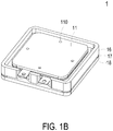
- FIG. 1B is a schematic assembled view illustrating the miniature pneumatic device of FIG. 1A .
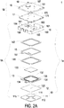
- FIG. 2A is a schematic exploded view illustrating the miniature pneumatic device according to the embodiment of the present invention and taken along a second viewpoint.
- FIG. 2B is a schematic assembled view illustrating the miniature pneumatic device of FIG. 2A .
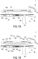
- FIGS. 7A to 7E schematically illustrate a gas-collecting operation of the miniature pneumatic device of FIG. 1A .
- the miniature pneumatic device 1 comprises a miniature fluid control device 1A and a miniature valve device 1B.
- the miniature fluid control device 1A comprises a housing 1a, a piezoelectric actuator 13, a first insulation plate 141, a conducting plate 15 and a second insulation plate 142.
- the housing 1a comprises a gas collecting plate 16 and a base 10.
- the base 10 comprises a gas inlet plate 11 and a resonance plate 12.
- the piezoelectric actuator 13 is aligned with the resonance plate 12.
- the gas inlet plate 11, the resonance plate 12, the piezoelectric actuator 13, the first insulation plate 141, the conducting plate 15, the second insulation plate 142 and the gas collecting plate 16 are stacked on each other sequentially.
- the piezoelectric actuator 13 comprises a suspension plate 130, an outer frame 131, at least one bracket 132 and a piezoelectric ceramic plate 133.
- the miniature valve device 1B comprises a valve plate 17 and a gas outlet plate 18.
- the gas collecting plate 16 comprises a bottom plate and a sidewall 168.
- the sidewall 168 is protruded from the edges of the bottom plate.
- the length of the gas collecting plate 16 is in the range between 9mm and 17mm.
- the width of the gas collecting plate 16 is in the range between 9mm and 17mm.
- the length/width ratio of the gas collecting plate 16 is in the range between 0.53 and 1.88.
- an accommodation space 16a is defined by the bottom plate and the sidewall 168 collaboratively.
- the piezoelectric actuator 13 is disposed within the accommodation space 16a.
- the miniature fluid control device 1A and the miniature valve device 1B are combined together. That is, the valve plate 17 and the gas outlet plate 18 of the miniature valve device 1B are stacked on each other and positioned on the gas collecting plate 16 of the miniature fluid control device 1A.
- the gas outlet plate 18 comprises a pressure-releasing perforation 181 and an outlet structure 19.
- the outlet structure 19 is in communication with an equipment (not shown). When the gas in the miniature valve device 1B releases from the pressure-releasing perforation 181, the pressure-releasing purpose is achieved.
- the miniature pneumatic device 1 is assembled. Consequently, a gas is fed into the miniature fluid control device 1A through at least one inlet 110 of the gas inlet plate 11. In response to the actions of the piezoelectric actuator 13, the gas is transferred downwardly through plural pressure chambers (not shown). Then, the gas is transferred through the miniature valve device 1B in one direction. The pressure of the gas is accumulated in an equipment (not shown) that is in communication with the outlet structure 19 of the miniature valve device 1B. For releasing the pressure, the output gas amount of the miniature fluid control device 1A is exited from the pressure-releasing perforation 181 of the gas outlet plate 18 of the miniature valve device 1B.
- the gas inlet plate 11 of the miniature fluid control device 1A comprises a first surface 11b, a second surface 11a and the at least one inlet 110.
- the gas inlet plate 11 comprises four inlets 110.
- the inlets 110 run through the first surface 11b and the second surface 11a of the gas inlet plate 11.
- the gas can be introduced into the miniature fluid control device 1A through the at least one inlet 110.
- at least one convergence channel 112 is formed in the first surface 11b of the gas inlet plate 11.
- the at least one convergence channel 112 is in communication with the at least one inlet 110 in the second surface 11a of the gas inlet plate 11.
- the number of the at least one convergence channel 112 is identical to the number of the at least one inlet 110.
- the gas inlet plate 11 comprises four convergence channels 112. It is noted that the number of the at least one convergence channel 112 and the number of the at least one inlet 110 may be varied according to the practical requirements.
- a central cavity 111 is formed in the first surface 11b of the gas inlet plate 11 and located at a central convergence area of the four convergence channels 112. The central cavity 111 is in communication with the at least one convergence channel 112. After the gas is introduced into the at least one convergence channel 112 through the at least one inlet 110, the gas is guided to the central cavity 111.
- the at least one inlet 110, the at least one convergence channel 112 and the central cavity 111 of the gas inlet plate 11 are integrally formed.
- the central cavity 111 is a convergence chamber for temporarily storing the gas.
- the gas inlet plate 11 is made of stainless steel.
- the thickness of the gas inlet plate 11 is in the range between 0.4mm and 0.6mm, and preferably 0.5mm.
- the depth of the convergence chamber defined by the central cavity 111 and the depth of the at least one convergence channel 112 are equal.
- the resonance plate 12 is made of flexible material.
- the resonance plate 12 comprises a central aperture 120 corresponding to the central cavity 111 of the gas inlet plate 11. Consequently, the gas can be transferred downwardly through the central aperture 120.
- the resonance plate 12 is made of copper.
- the thickness of the resonance plate 12 is in the range between 0.03mm and 0.08mm, and preferably 0.05mm.
- FIG. 3A is a schematic perspective view illustrating the piezoelectric actuator of the miniature pneumatic device of FIG. 1A and taken along the front side.
- FIG. 3B is a schematic perspective view illustrating the piezoelectric actuator of the miniature pneumatic device of FIG 1A and taken along the rear side.
- FIG 3C is a schematic cross-sectional view illustrating the piezoelectric actuator of the miniature pneumatic device of FIG. 1A .
- the piezoelectric actuator 13 comprises the suspension plate 130, the outer frame 131, the at least one bracket 132, and the piezoelectric ceramic plate 133.
- the piezoelectric ceramic plate 133 is attached on a first surface 130b of the suspension plate 130.
- the piezoelectric ceramic plate 133 is subjected to a curvy vibration in response to an applied voltage.
- the suspension plate 130 comprises a middle portion 130d and a periphery portion 130e.
- the suspension plate 130 is subjected to the curvy vibration from the middle portion 130d to the periphery portion 130e.
- the at least one bracket 132 is arranged between the suspension plate 130 and the outer frame 131. That is, the at least one bracket 132 is connected between the suspension plate 130 and the outer frame 131.
- the two ends of the bracket 132 are connected with the outer frame 131 and the suspension plate 130, respectively. Consequently, the bracket 131 can elastically support the suspension plate 130.
- At least one vacant space 135 is formed between the bracket 132, the suspension plate 130 and the outer frame 131 for allowing the gas to go through.
- the type of the suspension plate 130 and the outer frame 131 and the type and the number of the at least one bracket 132 may be varied according to the practical requirements.
- a conducting pin 134 is protruded outwardly from the outer frame 131 so as to be electrically connected with an external circuit (not shown).
- the suspension plate 130 is a stepped structure. That is, the suspension plate 130 comprises a bulge 130c.
- the bulge 130c is formed on a second surface 130a of the suspension plate 130.
- the bulge 130c is a circular convex structure.
- the thickness of the bulge 130c is in the range between 0.02mm and 0.08mm, and preferably 0.03mm.
- the diameter of the bulge 130c is 0.55 times the short side length of the suspension plate 130. As shown in FIGS.
- a top surface of the bulge 130c of the suspension plate 130 is coplanar with a second surface 131a of the outer frame 131, and the second surface 130a of the suspension plate 130 is coplanar with a second surface 132a of the bracket 132.
- the bulge 130c of the suspension plate 130 (or the second surface 131a of the outer frame 131) has a specified thickness with respect to the second surface 130a of the suspension plate 130 (or the second surface 132a of the bracket 132).
- a first surface 130b of the suspension plate 130, a first surface 131b of the outer frame 131 and a first surface 132b of the bracket 132 are coplanar with each other.
- the piezoelectric ceramic plate 133 is attached on the first surface 130b of the suspension plate 130.
- the suspension plate 130 is a square plate structure with two flat surfaces. That is, the structure of the suspension plate 130 may be varied according to the practical requirements.
- the suspension plate 130, the at least bracket 132 and the outer frame 131 are integrally formed and produced by using a metal plate (e.g., a stainless steel plate).
- the thickness of the suspension plate 130 is in the range between 0.1mm and 0.4mm, and preferably 0.27mm.
- the length of the suspension plate 130 is in the range between 7.5mm and 12mm, and preferably in the range between 7.5mm and 8.5mm.
- the width of the suspension plate 130 is in the range between 7.5mm and 12mm, and preferably in the range between 7.5mm and 8.5mm.
- the thickness of the outer frame 131 is in the range between 0.2mm and 0.4mm, and preferably 0.3mm.
- the thickness of the piezoelectric ceramic plate 133 is in the range between 0.05mm and 0.3mm, and preferably 0.10mm.
- the length of the piezoelectric ceramic plate 133 is not larger than the length of the suspension plate 130.
- the length of the piezoelectric ceramic plate 133 is in the range between 7.5mm and 12mm, and preferably in the range between 7.5mm and 8.5mm.
- the width of the piezoelectric ceramic plate 133 is in the range between 7.5mm and 12mm, and preferably in the range between 7.5mm and 8.5mm.
- the length/width ratio of the piezoelectric ceramic plate 133 is in the range between 0.625 and 1.6. In some embodiments, the length of the piezoelectric ceramic plate 133 is smaller than the length of the suspension plate 130.
- the piezoelectric ceramic plate 133 is a square plate structure corresponding to the suspension plate 130.
- the suspension plate 130 of the piezoelectric actuator 13 used in the miniature pneumatic device 1 of the present invention is a square suspension plate.
- the square suspension plate is more power-saving. The comparison between the consumed power and the operating frequency for the suspension plates of different types and sizes is shown in Table 1.
- Table 1 Type and size of suspension plate Operating frequency Consumed power Square (side length: 10mm) 18kHz 1.1W Circular (diameter: 10mm) 28kHz 1.5W Square (side length: 9mm) 22kHz 1.3W Circular (diameter: 9mm) 34kHz 2W Square (side length: 8mm) 27kHz 1.5W Circular (diameter: 8mm) 42kHz 2.5W
- the piezoelectric actuator with the square suspension plate (8mm ⁇ 10mm) is more power-saving than the piezoelectric actuator with the circular suspension plate (8mm ⁇ 10mm). That is, the piezoelectric actuator with the square suspension plate consumes less power. Generally, the consumed power of the capacitive load at the resonance frequency is positively related to the resonance frequency. Since the resonance frequency of the square suspension plate is obviously lower than that of the circular square suspension plate, the consumed power of the square suspension plate is lower. Since the square suspension plate is more power-saving than the circular suspension plate, the square suspension plate is suitably used in the wearable device. The fact that the square suspension plate is more power-saving than the circular suspension plate is realized according to the results of experiments rather than theoretical mathematic formulae.
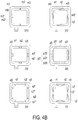
- FIGS. 4A , 4B and 4C schematically illustrate various exemplary piezoelectric actuator used in the miniature pneumatic device of the present invention.
- the suspension plate 130, the outer frame 131 and the at least one bracket 132 of the piezoelectric actuator 13 have various types.
- FIG. 4A schematically illustrates the types (a) ⁇ (1) of the piezoelectric actuator.
- the outer frame a1 and the suspension plate a0 are square, the outer frame a1 and the suspension plate a0 are connected with each other through eight brackets a2, and a vacant space a3 is formed between the brackets a2, the suspension plate a0 and the outer frame a1 for allowing the gas to go through.
- the outer frame i1 and the suspension plate i0 are also square, but the outer frame i1 and the suspension plate i0 are connected with each other through two brackets i2.
- the outer frame and the suspension plate in each of the types (b) ⁇ (h) are also square.
- the suspension plate is circular, and the outer frame has a square with arc-shaped corners.
- the suspension plate j0 is circular, and the outer frame has a square with arc-shaped corners.
- FIG 4B schematically illustrates the types (m) ⁇ (r) of the piezoelectric actuator.
- the suspension plate 130 and the outer frame 131 are square.
- the outer frame m1 and the suspension plate m0 are square, the outer frame m1 and the suspension plate m0 are connected with each other through four brackets m2, and a vacant space m3 is formed between the brackets m2, the suspension plate m0 and the outer frame m1 for allowing the gas to go through.
- the bracket m2 between the outer frame m1 and the suspension plate m0 is a connecting part.
- the bracket m2 has two ends m2' and m2".
- the end m2' of the bracket m2 is connected with the outer frame m1.
- the end m2" of the bracket m2 is connected with the suspension plate m0.
- the two ends m2' and m2" are opposed to each other and arranged along the same horizontal line.
- the outer frame n1 and the suspension plate m0 are square, the outer frame n1 and the suspension plate n0 are connected with each other through four brackets n2, and a vacant space n3 is formed between the brackets n2, the suspension plate n0 and the outer frame n1 for allowing the gas to go through.
- the bracket n2 between the outer frame n1 and the suspension plate n0 is a connecting part.
- the bracket n2 has two ends n2' and n2".
- the end n2' of the bracket n2 is connected with the outer frame n1.
- the end n2" of the bracket n2 is connected with the suspension plate n0.
- the two ends n2' and n2" are not arranged along the same horizontal line. For example, the two ends n2' and n2" are inclined at 0 ⁇ 45 degrees with respect to the horizontal line, and the two ends n2' and n2" are interlaced.
- the outer frame o1 and the suspension plate o0 are square, the outer frame o1 and the suspension plate o0 are connected with each other through four brackets o2, and a vacant space o3 is formed between the brackets o2, the suspension plate o0 and the outer frame o1 for allowing the gas to go through.
- the bracket o2 between the outer frame o1 and the suspension plate o0 is a connecting part.
- the bracket o2 has two ends o2' and o2".
- the end o2' of the bracket o2 is connected with the outer frame o1.
- the end o2" of the bracket o2 is connected with the suspension plate o0.
- the two ends o2' and o2" are opposed to each other and arranged along the same horizontal line. In comparison with the above types, the profile of the bracket o2 is distinguished.
- the outer frame p1 and the suspension plate p0 are square, the outer frame p1 and the suspension plate p0 are connected with each other through four brackets p2, and a vacant space p3 is formed between the brackets p2, the suspension plate p0 and the outer frame p1 for allowing the gas to go through.
- the bracket p2 between the outer frame p1 and the suspension plate p0 comprises a first connecting part p20, an intermediate part p21 and a second connecting part p22.
- the intermediate part p21 is formed in the vacant space p3 and in parallel with the outer frame p1 and the suspension plate p0.
- the first connecting part p20 is arranged between the intermediate part p21 and the suspension plate p0.
- the second connecting part p22 is arranged between the intermediate part p21 and the outer frame p1.
- the first connecting part p20 and the second connecting part p22 are opposed to each other and arranged along the same horizontal line.
- the outer frame q1, the suspension plate q0, the bracket q2 and the vacant space q3 are similar to those of the type (m) and the type (o). However, the structure of the bracket q2 is distinguished.
- the suspension plate q0 is square. Each side of the suspension plate q0 is connected with the corresponding side of the outer frame q1 through two connecting parts q2. The two ends q2' and q2" of each connecting part q2 are opposed to each other and arranged along the same horizontal line.
- the outer frame r1, the suspension plate r0, the bracket r2 and the vacant space r3 are similar to those of the above embodiments. However, the bracket r2 is a V-shaped connecting part.
- bracket r2 is connected with the outer frame r1 and the suspension plate r0 at an inclined angle 0 ⁇ 45 degrees.
- An end r2" of the bracket r2 is connected with the suspension plate r0, and two ends r2' of the bracket r2 is connected with the outer frame r1. That is, the ends b2' and b2" are not arranged along the same horizontal line.
- FIG 4C schematically illustrates the types (s) ⁇ (x) of the piezoelectric actuator.
- the structures of the types (s) ⁇ (x) are similar to those of the types (m) ⁇ (r), respectively.
- the suspension plate 130 of the piezoelectric actuator 13 has a bulge 130c.
- the bulges 130c in the types (s) ⁇ (x) are indicated as s4, t4, u4, v4, w4 and x4, respectively.
- the suspension plate 130 is square, and thus the power-saving efficacy is achieved.
- the stepped structure comprising the bulge and the square plate structure with two flat surfaces are suitably used as the suspension plates of the present invention.
- the number of the brackets 132 between the outer frame 131 and the suspension plate 130 may be varied according to the practical requirements.
- the suspension plate 130, the outer frame 131 and the at least one bracket 132 are integrally formed with each other and produced by a conventional machining process, a photolithography and etching process, a laser machining process, an electroforming process, an electric discharge machining process and so on.
- the miniature fluid control device 1A further comprises the first insulation plate 141, the conducting plate 15 and the second insulation plate 142.
- the first insulation plate 141, the conducting plate 15 and the second insulation plate 142 are stacked on each other sequentially and located under the piezoelectric actuator 13.
- the profiles of the first insulation plate 141, the conducting plate 15 and the second insulation plate 142 substantially match the profile of the outer frame 131 of the piezoelectric actuator 13.
- the first insulation plate 141 and the second insulation plate 142 are made of an insulating material (e.g. a plastic material) for providing insulating efficacy.
- the conducting plate 15 is made of an electrically conductive material (e.g. a metallic material) for providing electrically conducting efficacy.
- the conducting plate 15 has a conducting pin 151 so as to be electrically connected with an external circuit (not shown).
- FIGS. 5A to 5E schematically illustrate the actions of the miniature fluid control device of the miniature pneumatic device of FIG. 1A .
- the gas inlet plate 11, the resonance plate 12, the piezoelectric actuator 13, the first insulation plate 141, the conducting plate 15 and the second insulation plate 142 of the miniature fluid control device 1A are stacked on each other sequentially.
- a filler e.g. a conductive adhesive
- the depth of the gap g0 between the resonance plate 12 and the bulge 130c of the suspension plate 130 can be maintained to guide the gas to flow more quickly.
- the contact interference is reduced and the generated noise is largely reduced.
- a convergence chamber for converging the gas is defined by the central aperture 120 of the resonance plate 12 and the gas inlet plate 11 collaboratively, and a first chamber 121 is formed between the resonance plate 12 and the piezoelectric actuator 13 for temporarily storing the gas.
- the first chamber 121 is in communication with the central cavity 111 that is formed in the first surface 11b of the gas inlet plate 11.
- the peripheral regions of the first chamber 121 are in communication with the underlying miniature valve device 1B through the vacant space 135 of the piezoelectric actuator 13.
- the piezoelectric actuator 13 When the miniature fluid control device 1A of the miniature pneumatic device 1 is enabled, the piezoelectric actuator 13 is actuated by an applied voltage. Consequently, the piezoelectric actuator 13 is vibrated along a vertical direction in a reciprocating manner by using the bracket 132 as a fulcrum.
- the resonance plate 12 is light and thin. Please refer to FIG. 5B .
- the piezoelectric actuator 13 When the piezoelectric actuator 13 is vibrated downwardly in response to the applied voltage, the resonance plate 12 is vibrated along the vertical direction in the reciprocating manner because of the resonance of the piezoelectric actuator 13. More especially, the portion of the resonance plate 12 corresponding to the central cavity 111 of the gas inlet plate 11 is also subjected to a curvy deformation.
- the region of the resonance plate 12 corresponding to the central cavity 111 of the gas inlet plate 11 is also referred as a movable part 12a of the resonance plate 12.
- the piezoelectric actuator 13 When the piezoelectric actuator 13 is vibrated downwardly, the movable part 12a of the resonance plate 12 is subjected to the curvy deformation because the movable part 12a of the resonance plate 12 is pushed by the gas and vibrated in response to the piezoelectric actuator 13.
- the gas is fed into the at least one inlet 110 of the gas inlet plate 11, the gas is transferred to the central cavity 111 of the gas inlet plate 11 through the at least one convergence channel 112. Then, the gas is transferred through the central aperture 120 of the resonance plate 12, and introduced downwardly into the first chamber 121.
- the piezoelectric actuator 13 As the piezoelectric actuator 13 is actuated, the resonance of the resonance plate 12 occurs. Consequently, the movable part 12 of the resonance plate 12 is also vibrated along the vertical direction in the reciprocating manner.
- the resonance plate 12 is vibrated downwardly and contacted with the bulge 130c of the suspension plate 130 of the piezoelectric actuator 13.
- the region of the resonance plate 12 excluding the movable part 12a is also referred as a fixed part 12b. Meanwhile, the gap between the suspension plate 130 and the fixed part 12b of the resonance plate 12 is not reduced. Due to the deformation of the resonance plate 12, the volume of the first chamber 121 is shrunken and a middle communication space of the first chamber 121 is closed. Under this circumstance, the gas is pushed toward peripheral regions of the first chamber 121. Consequently, the gas is transferred downwardly through the vacant space 135 of the piezoelectric actuator 13.
- the resonance plate 12 is returned to its original position after the movable part 12a of the resonance plate 12 is subjected to the curvy deformation. Then, the piezoelectric actuator 13 is vibrated upwardly in response to the applied voltage. Consequently, the volume of the first chamber 121 is also shrunken. Since the piezoelectric actuator 13 is ascended at a vibration displacement d, the gas is continuously pushed toward peripheral regions of the first chamber 121. Meanwhile, the gas is continuously fed into the at least one inlet 110 of the gas inlet plate 11, and transferred to the central cavity 111.
- the resonance plate 12 is moved upwardly because the piezoelectric actuator 13 is vibrated upwardly. That is, the movable part 12a of the resonance plate 12 is moved upwardly.
- the gas in the central cavity 111 is transferred to the first chamber 121 through the central aperture 120 of the resonance plate 12, then the gas is transferred downwardly through the vacant space 135 of the piezoelectric actuator 13, and finally the gas is exited from the miniature fluid control device 1A.
- the gap g0 between the resonance plate 12 and the piezoelectric actuator 13 is helpful to increase the amplitude of the resonance plate 12. That is, due to the gap g0 between the resonance plate 12 and the piezoelectric actuator 13, the amplitude of the resonance plate 12 is increased when the resonance occurs.
- a series of tests about the maximum output pressure of the miniature pneumatic device 1 corresponding to different values of x are performed. In case that x ⁇ 0 ⁇ m, the miniature pneumatic device 1 generates noise.
- Table 2 The relationships between the difference x and the maximum output pressure are listed in Table 2. The values of Table 2 are obtained when the operating frequency is in the range between 17kHz and 20kHz and the operating voltage is in the range between ⁇ 10V and ⁇ 20V. Consequently, a pressure gradient is generated in the fluid channels of the miniature fluid control device 1A to facilitate the gas to flow at a high speed.
- the vibration frequency of the resonance plate 12 along the vertical direction in the reciprocating manner is identical to the vibration frequency of the piezoelectric actuator 13. That is, the resonance plate 12 and the piezoelectric actuator 13 are synchronously vibrated along the upward direction or the downward direction. It is noted that numerous modifications and alterations of the actions of the miniature fluid control device 1A may be made while retaining the teachings of the invention.
- FIG. 6A schematically illustrates a gas-collecting operation of the gas collecting plate and miniature valve device of the miniature pneumatic device of FIG 1A .
- FIG. 6B schematically illustrates a gas-releasing operation of the gas collecting plate and miniature valve device of the miniature pneumatic device of FIG. 1A .
- the valve plate 17 and the gas outlet plate 18 of the miniature valve device 1B are stacked on each other sequentially.
- the miniature valve device 1B and the gas collecting plate 16 of the miniature fluid control device 1A cooperate with each other.
- the gas collecting plate 16 comprises a first surface 160 and a second surface 161 (also referred as a fiducial surface).
- the first surface 160 of the gas collecting plate 16 is concaved to define a gas-collecting chamber 162.
- the piezoelectric actuator 13 is accommodated within the gas-collecting chamber 162.
- the gas that is transferred downwardly by the miniature fluid control device 1A is temporarily accumulated in the gas-collecting chamber 162.
- the gas collecting plate 16 comprises a first perforation 163 and a second perforation 164. A first end of the first perforation 163 and a first end of the second perforation 164 are in communication with the gas-collecting chamber 162.
- a second end of the first perforation 163 and a second end of the second perforation 164 are in communication with a first pressure-releasing chamber 165 and a first outlet chamber 166, which are formed in the second surface 161 of the gas collecting plate 16.
- the gas collecting plate 16 has a raised structure 167 corresponding to the first outlet chamber 166.
- the raised structure 167 includes but is not limited to a cylindrical post.
- the raised structure 167 is located at a level higher than the second surface 161 of the gas collecting plate 16.
- a thickness of the raised structure 167 is in a range between 0.3mm and 0.55mm, and preferably 0.4mm.
- the gas outlet plate 18 comprises a pressure-releasing perforation 181, an outlet perforation 182, a first surface 180 (also referred as a fiducial surface) and a second surface 187.
- the pressure-releasing perforation 181 and the outlet perforation 182 run through the first surface 180 and the second surface 187.
- the first surface 180 of the gas outlet plate 18 is concaved to define a second pressure-releasing chamber 183 and a second outlet chamber 184.
- the pressure-releasing perforation 181 is located at a center of the second pressure-releasing chamber 183.
- the gas outlet plate 18 further comprises a communication channel 185 between the second pressure-releasing chamber 183 and the second outlet chamber 184 for allowing the gas to go through.
- a first end of the outlet perforation 182 is in communication with the second outlet chamber 184.
- a second end of the outlet perforation 182 is in communication with an outlet structure 19.
- the outlet structure 19 is in connected with an equipment (not shown).
- the equipment is for example but not limited to a gas-pressure driving equipment.
- the valve plate 17 comprises a valve opening 170 and plural positioning openings 171 (see FIG. 1A ).
- the thickness of the valve plate 17 is in the range between 0.1mm and 0.3mm, and preferably 0.2mm.
- the pressure-releasing perforation 181 of the gas outlet plate 18 is aligned with the first perforation 163 of the gas collecting plate 16
- the second pressure-releasing chamber 183 of the gas outlet plate 18 is aligned with the first pressure-releasing chamber 165 of the gas collecting plate 16
- the second outlet chamber 184 of the gas outlet plate 18 is aligned with the first outlet chamber 166 of the gas collecting plate 16.
- the valve plate 17 is arranged between the gas collecting plate 16 and the gas outlet plate 18 for blocking the communication between the first pressure-releasing chamber 165 and the second pressure-releasing chamber 183.
- the valve opening 170 of the valve plate 17 is arranged between the second perforation 164 and the outlet perforation 182.
- valve opening 170 of the valve plate 17 is aligned with the raised structure 167 corresponding to the first outlet chamber 166 of the gas collecting plate 16. Due to the arrangement of the single valve opening 170, the gas is transferred through the miniature valve device 1B in one direction in response to the pressure difference.
- the gas outlet plate 18 has the convex structure 181a beside a first end of the pressure-releasing perforation 181.
- the convex structure 181a is a cylindrical post.
- the thickness of the convex structure 181a is in the range between 0.3mm and 0.55mm, and preferably 0.4mm.
- the top surface of the convex structure 181a is located at a level higher than the first surface 180 of the gas outlet plate 18. Consequently, the pressure-releasing perforation 181 can be quickly contacted with and closed by the valve plate 17.
- the convex structure 181a can provide a pre-force to achieve a good sealing effect.
- the gas outlet plate 18 further comprises a position-limiting structure 188.
- the thickness of the position-limiting structure 188 is 0.32mm.
- the position-limiting structure 188 is disposed within the second pressure-releasing chamber 183.
- the position-limiting structure 188 is a ring-shaped structure. While the gas-collecting operation of the miniature valve device 1B is performed, the position-limiting structure 188 can assist in supporting the valve plate 17 and avoid collapse of the valve plate 17. Consequently, the valve plate 17 can be opened or closed more quickly.
- the gas-collecting operation of the miniature valve device 1B will be illustrated with reference to FIG. 6A .
- the gas from the miniature fluid control device 1A is transferred downwardly to the miniature valve device 1B or the ambient air pressure is higher than the inner pressure of the equipment which is in communication with the outlet structure 19, the gas will be transferred from the miniature fluid control device 1A to the gas-collecting chamber 162 of the gas collecting plate 16. Then, the gas is transferred downwardly to the first pressure-releasing chamber 165 and the first outlet chamber 166 through the first perforation 163 and the second perforation 164.
- the flexible valve plate 17 is subjected to a downward curvy deformation.
- the volume of the first pressure-releasing chamber 165 is expanded, and the valve plate 17 is in close contact with the first end of the pressure-releasing perforation 181 corresponding to the first perforation 163.
- the pressure-releasing perforation 181 of the gas outlet plate 18 is closed, and thus the gas within the second pressure-releasing chamber 183 is not leaked out from the pressure-releasing perforation 181.
- the gas outlet plate 18 has the convex structure 181a beside of the first end of the pressure-releasing perforation 181. Due to the arrangement of the convex structure 181a, the pressure-releasing perforation 181 can be quickly closed by the valve plate 17.
- the convex structure 181a can provide a pre-force to achieve a good sealing effect.
- the position-limiting structure 188 is arranged around the pressure-releasing perforation 181 to assist in supporting the valve plate 17 and avoid collapse of the valve plate 17.
- the gas is transferred downwardly to the first outlet chamber 166 through the second perforation 164.
- the valve plate 17 corresponding to the first outlet chamber 166 is also subjected to the downward curvy deformation. Consequently, the valve opening 170 of the valve membrane 17 is correspondingly opened to the downward side.
- the gas is transferred from the first outlet chamber 166 to the second outlet chamber 184 through the valve opening 170.
- the gas is transferred to the outlet structure 19 through the outlet perforation 182 and then transferred to the equipment which is in communication with the outlet structure 19. Consequently, the purpose of collecting the gas pressure is achieved.
- the gas-releasing operation of the miniature valve device 1B will be illustrated with reference to FIG. 6B .
- the user may adjust the amount of the gas to be fed into the miniature fluid control device 1A, so that the gas is no longer transferred to the gas-collecting chamber 162.
- the gas-releasing operation may be performed. Under this circumstance, the gas is transferred from the outlet structure 19 to the second outlet chamber 184 through the outlet perforation 182. Consequently, the volume of the second outlet chamber 184 is expanded, and the flexible valve plate 17 corresponding to the second outlet chamber 184 is subjected to the upward curvy deformation.
- valve plate 17 is in close contact with the gas collecting plate 16. Consequently, the valve opening 170 of the valve plate 17 is closed by the gas collecting plate 16.
- the gas collecting plate 16 has the raised structure 167 corresponding to the first outlet chamber 166. Due to the arrangement of the raised structure 167, the flexible valve plate 17 can be bent upwardly more quickly. Moreover, the raised structure 167 can provide a pre-force to achieve a good sealing effect of the valve opening 170. Since the valve opening 170 of the valve plate 17 is contacted with and closed by the raised structure 167, the gas in the second outlet chamber 184 will not be reversely returned to the first outlet chamber 166. Consequently, the efficacy of avoiding gas leakage is enhanced.
- the valve plate 17 corresponding to the second pressure-releasing chamber 183 is also subjected to the upward curvy deformation. Since the valve plate 17 is no longer in contact with the first end of the pressure-releasing perforation 181, the pressure-releasing perforation 181 is opened. Under this circumstance, the gas in the second pressure-releasing chamber 183 is outputted through the pressure-releasing perforation 181. Consequently, the pressure of the gas is released.
- the flexible valve plate 17 can be subjected to the upward curvy deformation more quickly. Consequently, the pressure-releasing perforation 181 can be quickly opened. After the gas-releasing operation in one direction is performed, the gas within the equipment which is in communication with the outlet structure 19 is partially or completely exited to the surrounding. Under this circumstance, the pressure of the equipment is reduced.
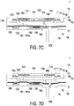
- FIGS. 7A to 7E schematically illustrate the gas-collecting actions of the miniature pneumatic device of FIG. 2A .
- the miniature pneumatic device 1 comprises the miniature fluid control device 1A and the miniature valve device 1B.
- the gas inlet plate 11, the resonance plate 12, the piezoelectric actuator 13, the first insulation plate 141, the conducting plate 15, the second insulation plate 142 and the gas collecting plate 16 of the miniature fluid control device 1A are stacked on each other sequentially.
- the first chamber 121 is formed between the resonance plate 12 and the piezoelectric actuator 13.
- the valve plate 17 and the gas outlet plate 18 of the miniature valve device 1B are stacked on each other and disposed under the gas collecting plate 16 of the miniature fluid control device 1A.
- the gas-collecting chamber 162 is arranged between the gas collecting plate 16 and the piezoelectric actuator 13.
- the first pressure-releasing chamber 165 and the first outlet chamber 166 are formed in the second surface 161 of the gas collecting plate 16.
- the second pressure-releasing chamber 183 and the second outlet chamber 184 are formed in the first surface 180 of the gas outlet plate 18.
- the operating frequency of the miniature pneumatic device 1 is in the range between 27kHz and 29.5kHz
- the operating voltage of the miniature pneumatic device 1 is in the range between ⁇ 10V and ⁇ 16V.
- the actuation of the piezoelectric actuator 13 and the vibration of the plate 12 and the valve plate 17, the gas can be transferred downwardly.
- the piezoelectric actuator 13 of the miniature fluid control device 1A is vibrated downwardly in response to the applied voltage. Consequently, the gas is fed into the miniature fluid control device 1A through the at least one inlet 110 of the gas inlet plate 11. The gas is sequentially converged to the central cavity 111 through the at least one convergence channel 112 of the gas inlet plate 11, transferred through the central aperture 120 of the resonance plate 12, and introduced downwardly into the first chamber 121.
- the resonance plate 12 As the piezoelectric actuator 13 is actuated, the resonance of the resonance plate 12 occurs. Consequently, the resonance plate 12 is also vibrated along the vertical direction in the reciprocating manner. As shown in FIG. 7C , the resonance plate 12 is vibrated downwardly and contacted with the bulge 130c of the suspension plate 130 of the piezoelectric actuator 13. Due to the deformation of the resonance plate 12, the volume of the chamber corresponding to the central cavity 111 of the gas inlet plate 11 is expanded but the volume of the first chamber 121 is shrunken. Under this circumstance, the gas is pushed toward peripheral regions of the first chamber 121. Consequently, the gas is transferred downwardly through the vacant space 135 of the piezoelectric actuator 13.
- the gas is transferred to the gas-collecting chamber 162 between the miniature fluid control device 1A and the miniature valve device 1B. Then, the gas is transferred downwardly to the first pressure-releasing chamber 165 and the first outlet chamber 166 through the first perforation 163 and the second perforation 164, which are in communication with the gas-collecting chamber 162. Consequently, when the resonance plate 12 is vibrated along the vertical direction in the reciprocating manner, the gap g0 between the resonance plate 12 and the piezoelectric actuator 13 is helpful to increase the amplitude of the resonance plate 12. That is, due to the gap g0 between the resonance plate 12 and the piezoelectric actuator 13, the amplitude of the resonance plate 12 is increased when the resonance occurs.
- the resonance plate 12 of the miniature fluid control device 1A is returned to its original position, and the piezoelectric actuator 13 is vibrated upwardly in response to the applied voltage.
- a series of tests about the maximum output pressure of the miniature pneumatic device 1 corresponding to different values of x are performed.
- the operating frequency of the miniature pneumatic device 1 is in the range between 27kHz and 29.5kHz, and the operating voltage of the miniature pneumatic device 1 is in the range between ⁇ 10V and ⁇ 16V.
- the maximum output pressure of the miniature pneumatic device 1 is at least 300mmHg. Consequently, the volume of the first chamber 121 is also shrunken, and the gas is continuously pushed toward peripheral regions of the first chamber 121. Moreover, the gas is continuously transferred to the gas-collecting chamber 162, the first pressure-releasing chamber 165 and the first outlet chamber 166 through the vacant space 135 of the piezoelectric actuator 13. Consequently, the pressure in the first pressure-releasing chamber 165 and the first outlet chamber 166 will be gradually increased. In response to the increased gas pressure, the flexible valve plate 17 is subjected to the downward curvy deformation.
- valve plate 17 corresponding to the second pressure-releasing chamber 183 is moved downwardly and contacted with the convex structure 181a corresponding to the first end of the pressure-releasing perforation 181.
- the pressure-releasing perforation 181 of the gas outlet plate 18 is closed.
- the valve opening 170 of the valve plate 17 corresponding to the outlet perforation 182 is opened downwardly.
- the gas within the second outlet chamber 184 is transferred downwardly to the outlet structure 19 through the outlet perforation 182 and then transferred to the equipment which is in communication with the outlet structure 19. Consequently, the purpose of collecting the gas pressure is achieved.
- the resonance plate 12 of the miniature fluid control device 1A is vibrated upwardly.
- the gas in the central cavity 111 of the gas inlet plate 11 is transferred to the first chamber 121 through the central aperture 120 of the resonance plate 12, and then the gas is transferred downwardly to the gas collecting plate 16 through the vacant space 135 of the piezoelectric actuator 13.
- the gas pressure is continuously increased along the downward direction, the gas is continuously transferred to the gas-collecting chamber 162, the second perforation 164, the first outlet chamber 166, the second outlet chamber 184 and the outlet perforation 182 and then transferred to the equipment which is in communication with the outlet structure 19.
- the pressure-collecting operation is triggered by the pressure difference between the ambient pressure and the inner pressure of the equipment.
- FIG. 8 schematically illustrates the gas-releasing actions or the pressure-reducing actions of the miniature pneumatic device of FIG. 1A .
- the gas-releasing operation (or a pressure-reducing operation) may be performed.
- the user may adjust the amount of the gas to be fed into the miniature fluid control device 1A, so that the gas is no longer transferred to the gas-collecting chamber 162.
- the gas is transferred from the outlet structure 19 to the second outlet chamber 184 through the outlet perforation 182. Consequently, the volume of the second outlet chamber 184 is expanded, and the flexible valve plate 17 corresponding to the second outlet chamber 184 is bent upwardly.
- valve plate 17 is in close contact with the raised structure 167 corresponding to the first outlet chamber 166. Since the valve opening 170 of the valve plate 17 is closed by the raised structure 167, the gas in the second outlet chamber 184 will not be reversely returned to the first outlet chamber 166. Moreover, the gas in the second outlet chamber 184 is transferred to the second pressure-releasing chamber 183 through the communication channel 185, and then the gas in the second pressure-releasing chamber 183 is transferred to the pressure-releasing perforation 181. Under this circumstance, the gas-releasing operation is performed. After the gas-releasing operation of the miniature valve device 1B in one direction is performed, the gas within the equipment which is in communication with the outlet structure 19 is partially or completely exited to the surrounding. Under this circumstance, the inner pressure of the equipment is reduced.
- Table 3 The performance data of the miniature pneumatic device with different sizes of square suspension plates are listed in Table 3.
- Table 3 Side length of square suspension plate 7.5mm 8mm 8.5mm 10mm 12mm 14mm Frequency 28 kHz 27 kHz 27 kHz 18 kHz 15 kHz 15 kHz Maximum output pressure 400 mmHg 400 mmHg 320 mmHg 300.
- the results of the above table are obtained by testing 25 samples of the miniature pneumatic device with different sizes of square suspension plates.
- the side length of the square suspension plate is in the range between 7.5mm and 14mm. As the side length of the square suspension plate is decreased, the yield and the maximum output pressure are both increased.
- the optimized side length of the square suspension plate is in the range between 7.5mm and 8.5mm.
- the operating frequency corresponding to the optimized side length is in the range between 27kHz and 29.5kHz, and the maximum output pressure is at least 300mmHg. It is presumed that the deformation amount in the horizontal direction is reduced in response to the vertical vibration of the suspension plate. That is, the kinetic energy in the vertical direction can be effectively utilized.
- the side length of the suspension plate is decreased, the assembling error in the vertical direction is also decreased. Consequently, the collision interference between the suspension plate and the resonance plate or other component can be reduced, and a specified distance between the suspension plate and the resonance plate can be maintained. Under this circumstance, the product yield is enhanced, and the maximum output pressure is increased.
- the size of the suspension plate is reduced, the size of the piezoelectric actuator can be correspondingly reduced. Since the piezoelectric actuator is not readily inclined during vibration, the volume of the gas channel is reduced and the efficacy of pushing or compressing the gas is increased. Consequently, the miniature pneumatic device of the present invention has enhanced performance and small size.
- the suspension plate and the piezoelectric ceramic plate of the piezoelectric actuator are larger, the suspension plate is readily suffered from distortion during vibration because the rigidity of the suspension plate is deteriorated. If the distortion of the suspension plate occurs, the collision interference between the suspension plate and the resonance plate or other component is increased and thus the noise is generated.
- the noise problem may result in the defective product. That is, as the size of the suspension plate and the size of the piezoelectric ceramic plate are increased, the defect rate of the miniature pneumatic device is increased. By reducing the size of the suspension plate and the size of the piezoelectric ceramic plate, the performance of the miniature pneumatic device is increased, the noise is reduced, and the defect rate is reduced.
- the total thickness of the miniature pneumatic device 1 is in the range between 2mm and 6mm. Since the miniature pneumatic device is slim and portable, the miniature pneumatic device is suitably applied to medical equipment or any other appropriate equipment.
- the present invention provides the miniature pneumatic device.
- the miniature pneumatic device comprises the miniature fluid control device and the miniature valve device. After the gas is fed into the miniature fluid control device through the inlet, the piezoelectric actuator is actuated. Consequently, a pressure gradient is generated in the fluid channels of the miniature fluid control device and the gas-collecting chamber to facilitate the gas to flow to the miniature valve device at a high speed. Moreover, due to the one-way valve plate of the miniature valve device, the gas is transferred in one direction. Consequently, the pressure of the gas is accumulated to any equipment that is connected with the outlet structure.
- the user may adjust the amount of the gas to be fed into the miniature fluid control device, so that the gas is no longer transferred to the gas-collecting chamber.
- the gas is transferred from the outlet structure to the second outlet chamber of the miniature valve device, then transferred to the second pressure-releasing chamber through the communication channel, and finally exited from the pressure-releasing perforation.
- the miniature pneumatic device of the present invention the gas can be quickly transferred while achieving silent efficacy.
- the miniature pneumatic device of the present invention has small volume and small thickness. Consequently, the miniature pneumatic device is portable and applied to medical equipment or any other appropriate equipment. In other words, the miniature pneumatic device of the present invention has industrial values.
Landscapes
- Engineering & Computer Science (AREA)
- General Engineering & Computer Science (AREA)
- Mechanical Engineering (AREA)
- Chemical & Material Sciences (AREA)
- Dispersion Chemistry (AREA)
- Physics & Mathematics (AREA)
- Fluid Mechanics (AREA)
- Reciprocating Pumps (AREA)
Claims (12)
- Un dispositif pneumatique miniature (1), comprenant:
un dispositif miniature de commande de fluide (1A) comprenant:une plaque d'entrée de gaz (11) comprenant au moins une entrée (110), au moins un canal de convergence (112) et une cavité centrale (111), dans lequel une chambre de convergence est définie par la cavité centrale (111), configuré de manière à que la suite de l'introduction d'un gaz est introduit dans le ou les canal/canaux de convergence (112) à travers la ou les entrée(s) (110), le gaz est guidé par le canal ou les canaux de convergence (112) et converge vers la chambre de convergence;une plaque de résonance (12) ayant une ouverture centrale (120) correspondant à la chambre de convergence de la plaque d'entrée de gaz (11);un actionneur piézoélectrique (13) comprenant:une plaque de suspension (130), dans laquelle une longueur de la plaque de suspension (130) est comprise dans une plage entre 7,5 mm et 12 mm, une largeur de la plaque de suspension (130) est comprise dans une plage entre 7,5 mm et 12 mm, et une épaisseur de la plaque de suspension (130) est comprise dans une plage entre 0,1 mm et 0,4 mm;un cadre extérieur (131), dans lequel la plaque de suspension (130) et le cadre extérieur (131) sont reliés l'un à l'autre par au moins un support (132); etune plaque céramique piézoélectrique (133), fixée sur une première surface (130b) de la plaque de suspension (130), dans laquelle une longueur de la plaque céramique piézoélectrique (133) n'est pas supérieure à une longueur de la plaque de suspension (130), la longueur de la plaque céramique piézoélectrique (133) est dans une plage comprise entre 7,5 mm et 12 mm, une largeur de la plaque céramique piézoélectrique (133) est comprise dans une plage entre 7,5 mm et 12 mm, une épaisseur de la plaque céramique piézoélectrique (133) est dans une plage entre 0,05 mm et 0,3 mm, et un rapport longueur/largeur de la plaque céramique piézoélectrique (133) est dans une plage entre 0,625 et 1,6; etune plaque collectrice de gaz (16) comprenant une première perforation (163), une seconde perforation (164), une première chambre de décompression (165), une première chambre de sortie (166) et une surface de référence (161), dans lequel la plaque collectrice de gaz (16) comprend en outre une structure surélevée (167) correspondant à la première chambre de sortie (166), la structure surélevée (167) étant située à un niveau plus élevé que la surface de référence (161) de la plaque collectrice de gaz (16), la première perforation (163) étant en communication avec la première chambre de décompression (165), et la seconde perforation (164) est en communication avec la première chambre de sortie (166),dans laquelle la plaque d'entrée de gaz (11), la plaque de résonance (12), l'actionneur piézoélectrique (13) et la plaque collectrice de gaz (16) sont empilés l'un sur l'autre séquentiellement, et un espace est formé entre la plaque de résonance (12) et l'actionneur piézoélectrique (13) pour définir un première chambre (121), dans laquelle lorsque l'actionneur piézoélectrique (13) est entraîné et après l'introduction du gaz dans le dispositif miniature de commande de fluide (1A) par la ou les entrée(s) (110) de la plaque d'entrée de gaz (11), le gaz converge séquentiellement vers la cavité centrale (111) par le canal ou les canaux de convergence (112), transférée à travers l'ouverture centrale (120) de la plaque de résonance (12), introduite dans la première chambre (121), transférée vers le bas à travers un espace vide entre le ou les supports (132) de l'actionneur piézoélectrique (13), et sorti du dispositif miniature de commande de fluide (1A); etun dispositif de soupape miniature (1B) comprenant:une plaque de soupape (17) ayant une ouverture de soupape (170), dans laquelle une épaisseur de la plaque de soupape (17) est dans une plage comprise entre 0,1 mm et 0,3 mm, dans lequel l'ouverture de soupape (170) de la plaque de soupape (17) est alignée avec la structure surélevée (167) de la plaque de collecte de gaz (16), et la structure surélevée (167) fournit une pré-force pour sceller l'ouverture de soupape (170); etune plaque de sortie de gaz (18) comprenant une perforation de décompression (181), une perforation de sortie (182), une deuxième chambre de décompression (183), une deuxième chambre de sortie (184), au moins une structure de limitation de position (188) et une surface de référence (180), dans laquelle la surface de référence (180) de la plaque de sortie de gaz (18) est concave pour définir la seconde chambre de décompression (183) et la seconde chambre de sortie (184), et la perforation de décompression (181) est située au centre de la seconde chambre de décompression (183), dans laquelle une structure convexe (181a) est située à côté d'une extrémité de la perforation de décompression (181), la structure convexe (181a) étant située à un niveau supérieur à la surface de référence (180) de la plaque de sortie de gaz (18), la perforation de sortie (182) étant en communication avec la seconde chambre de sortie (184), la ou les structure(s) de limitation de position (188) étant disposée(s) à l'intérieur de la seconde chambre de décompression (183), une épaisseur de la structure de limitation de position (188) étant dans une plage entre 0,2 mm et 0,5 mm, et la plaque de sortie de gaz (18) comprenant en outre un canal de communication (185) entre la seconde chambre de décompression (183) et la seconde chambre de sortie (184),dans lequel la plaque de collecte de gaz (16), la plaque de soupape (17) et la plaque de sortie de gaz (18) sont combinées ensemble, la perforation de décompression (181) de la plaque de sortie de gaz (18) étant alignée avec la première perforation (163) de la plaque de collecte de gaz (16), la seconde chambre de décompression (183) de la plaque de sortie de gaz (18) étant alignée avec la première chambre de décompression (165) de la plaque collectrice de gaz (16) et la seconde chambre de sortie (184) de la plaque de sortie de gaz (18) étant alignée avec la première chambre de sortie (166) de la plaque collectrice de gaz (16), dans lequel la plaque de soupape (17) est disposée entre la plaque de collecte de gaz (16) et la plaque de sortie de gaz (18) pour bloquer la communication entre la première chambre de décompression (165) et la seconde chambre de décompression (183), et l'ouverture de soupape (170) de la plaque de soupape (17) est disposée entre la seconde perforation (164) et la perforation de sortie (182), dans lequel après que le gaz est transféré vers le bas depuis le dispositif de commande de fluide miniature (1A) vers le dispositif de soupape miniature (1B), le gaz est introduit dans la première chambre de décompression (165) et la première chambre de sortie (166) à travers la première perforation (163) et la seconde perforation (164), et la plaque de soupape (17) est rapidement en contact avec la structure convexe (181a) de la plaque de sortie de gaz (18) pour fournir une pré-force pour fermer hermétiquement la perforation de décompression (181), et le gaz à l'intérieur de la première chambre de sortie (166) est en outre transféré vers la perforation de sortie (182) à travers l'ouverture de soupape (170) de la soupape plaque (17), de sorte qu'une opération de collecte de pression est effectuée, dans lequel, pendant qu'une opération de décompression est effectuée, le gaz est transféré de la perforation de sortie (182) à la seconde chambre de sortie (184) pour déplacer la plaque de soupape (7), l'ouverture de soupape (170) de la plaque de soupape (17) est en contact avec et fermée par la plaque de collecte de gaz (16), la ou les structure(s) de limitation de position (188) aidant à supporter la plaque de soupape (17) pour éviter l'affaissement de la plaque de soupape (17), le gaz étant transféré de la seconde chambre de sortie (184) à la deuxième chambre de décompression (183) par le canal de communication (185), la plaque de soupape (17) correspondant à la deuxième chambre de décompression (183) est déplacée, et le gaz est sorti de la perforation de décompression (181). - Le dispositif pneumatique miniature selon la revendication 1, dans lequel une fréquence de fonctionnement du dispositif pneumatique miniature (1) est dans une plage entre 27 kHz et 29,5 kHz, une tension de fonctionnement du dispositif pneumatique miniature (1) est dans une plage entre ± 10 V et ± 16 V, et une pression de sortie maximale du dispositif pneumatique miniature (1) est supérieure ou égale à 300 mmHg.
- Le dispositif pneumatique miniature selon la revendication 1 ou 2, dans lequel la longueur de la plaque de suspension (130) est dans une plage entre 7,5 mm et 8,5 mm, et la largeur de la plaque de suspension (130) est dans une plage entre 7,5 mm et 8,5 mm.
- Le dispositif pneumatique miniature selon l'une quelconque des revendications 1 à 3, dans lequel la longueur de la plaque céramique piézoélectrique (133) est dans une plage entre 7,5 mm et 8,5 mm, et la largeur de la plaque céramique piézoélectrique (133) est dans une gamme entre 7,5 mm et 8,5 mm.
- Le dispositif pneumatique miniature selon l'une quelconque des revendications 1 à 4, dans lequel la plaque de suspension (130) comprend en outre un renflement (130c), et le renflement (130c) est formé sur une seconde surface (130a) de la plaque de suspension (130), dans lequel le renflement (130c) est une structure convexe circulaire, et un diamètre du renflement (130c) est 0,55 fois plus grand qu'une petite longueur de côté de la plaque de suspension (130).
- Le dispositif pneumatique miniature selon l'une quelconque des revendications 1 à 5, dans lequel la plaque de résonance (12) est en cuivre, et une épaisseur de la plaque de résonance (12) est dans une plage comprise entre 0,03 mm et 0,08 mm.
- Le dispositif pneumatique miniature selon l'une quelconque des revendications 1 à 6, dans lequel le cadre extérieur (131) de l'actionneur piézoélectrique (13) est en acier inoxydable, et une épaisseur du cadre extérieur (131) est dans une plage comprise entre 0,2 mm et 0,4 mm.
- Le dispositif pneumatique miniature selon l'une quelconque des revendications 1 à 7, dans lequel une épaisseur de la structure de limitation de position (188) est de 0,32 mm.
- Un dispositif pneumatique miniature (1), comprenant:
un dispositif miniature de commande de fluide (1A) comprenant:une plaque d'entrée de gaz (11);une plaque de résonance (12);un actionneur piézoélectrique (13) comprenant une plaque de suspension; et une plaque collectrice de gaz (16) fixée sur une première surface de la plaque de suspension (130),dans lequel une longueur de la plaque céramique piézoélectrique (133) n'est pas supérieure à une longueur de la plaque de suspension (130), la longueur de la plaque céramique piézoélectrique (133) est dans une plage comprise entre 7,5 mm et 12 mm, une largeur de la plaque céramique piézoélectrique (133) est comprise entre 7,5 mm et 12 mm, une épaisseur de la plaque céramique piézoélectrique (133) est comprise entre 0,05 mm et 0,3 mm, et un rapport longueur / largeur de la plaque céramique piézoélectrique (133) est compris entre 0,625 et 1,6. ; etune plaque de collecte de gaz (16) comprenant une première perforation (163), une seconde perforation (164), une première chambre de détente (165) et une première chambre de sortie (166),dans laquelle la plaque d'entrée de gaz (11), la plaque de résonance (12), l'actionneur piézoélectrique (13) et la plaque collectrice de gaz (16) sont empilés l'un sur l'autre séquentiellement, et un espace est formé entre la plaque de résonance (12) et l'actionneur piézoélectrique (13) pour définir une première chambre (121), et une chambre de collecte de gaz (162) est formée entre l'actionneur piézoélectrique (13) et la plaque collectrice de gaz (16), dans lequel lorsque l'actionneur piézoélectrique (13) est entraîné et après qu'un gaz est introduit dans le dispositif miniature de commande de fluide (1A) à travers la plaque d'entrée de gaz (11), le gaz est transféré à travers la plaque de résonance (12), introduit dans la première chambre (121) et transféré vers le bas vers la chambre de collecte de gaz (16) ; etun dispositif de soupape miniature (1B) comprenant:une plaque de soupape (17) ayant une ouverture de soupape (170); etune plaque de sortie de gaz (18) comprenant une perforation de détente (181), une perforation de sortie (182), une seconde chambre de détente (183) et une seconde chambre de sortie (184),dans laquelle la plaque de collecte de gaz (16), la plaque de soupape (17) et la plaque de sortie de gaz (18) sont combinées ensemble, dans lequel après que le gaz est transféré vers le bas de la chambre de collecte de gaz (162) au dispositif de soupape miniature (1B), le gaz est transféré à travers la première perforation (163), la deuxième perforation (164), la première chambre de détente (165), la première chambre de sortie (166), la seconde chambre de détente (183), la seconde chambre de sortie (184), la perforation de détente (181) et la perforation de sortie (182), dans lesquelles le gaz est transféré dans une direction, et l'ouverture de soupape (170) de la plaque de soupape (17) est ouverte ou fermée en conséquence, de sorte qu'une pression une opération de collecte ou une opération de relâchement de la pression est effectuée de manière sélective. - Le dispositif pneumatique miniature selon la revendication 9, dans lequel la plaque d'entrée de gaz (11) comprend au moins une entrée (110), au moins un canal de convergence (112) et une cavité centrale (111), dans lequel après que le gaz est introduit dans le canal ou les canaux de convergence (112) à travers la ou les entrée(s) (110), le gaz est guidé par le canal ou les canaux de convergence (112) et converge vers la cavité centrale (111), dans lequel la plaque de résonance (12) a une ouverture centrale (120) correspondant à la cavité centrale (111) de la plaque d'entrée de gaz (11), et l'actionneur piézoélectrique (13) comprend un cadre extérieur (131), dans lequel la plaque de suspension (130) et le cadre extérieur (131) sont reliés l'un à l'autre par au moins un support (132).
- Le dispositif pneumatique miniature selon la revendication 9 ou 10, dans lequel la première perforation (163) est en communication avec la première chambre de détente (165), et la seconde perforation (164) est en communication avec la première chambre de sortie (166).
- Le dispositif pneumatique miniature selon la revendication 11, dans lequel la plaque de sortie de gaz (18) comprend en outre un canal de communication (185) entre la seconde chambre de détente (183) et la seconde chambre de sortie (184), dans lequel la plaque de soupape (17) est disposée entre la plaque collectrice de gaz (16) et la plaque de sortie de gaz (18) pour bloquer la communication entre la première chambre de détente (165) et la seconde chambre de détente (183), et l'ouverture de soupape (170) de la plaque de soupape (17) est disposée entre la deuxième perforation (164) et la perforation de sortie (182), dans lequel, après que le gaz est transféré vers le bas du dispositif de commande de fluide miniature (1A) au dispositif de soupape miniature (1B), le du gaz est introduit dans la première chambre de détente (165) et la première chambre de sortie (166) à travers la première perforation (163) et la seconde perforation (164), et la plaque de soupape (17) est rapidement mise en contact avec la structure convexe (181a) de la plaque de sortie de gaz (18) pour fournir une pré-force pour fermer hermétiquement la perforation de détente (181), et le gaz à l'intérieur de la première chambre de sortie (165) est en outre transféré vers la perforation de sortie (182) à travers l'ouverture de soupape (170) de la plaque de soupape (17), une pression du gaz est collectée, dans lequel pendant qu'une opération de détente est effectuée, le gaz est transféré de la perforation de sortie (182) vers la deuxième chambre de sortie (184) pour déplacer la plaque de soupape (17), l'ouverture de soupape (170) de la plaque de soupape (17) est en contact avec et fermée par la plaque de collecte de gaz (16), la ou les structure(s) de limitation de position (188) aide(nt) à supporter la plaque de soupape (17) pour éviter l'affaissement de la plaque de soupape (17), le gaz étant transféré de la deuxième chambre de sortie (184) vers la deuxième chambre de détente (183) par le canal de communication (185), la plaque de soupape (17) correspondant à la seconde chambre de détente (183) est déplacée, et le gaz sort de perforation de détente (181).
Applications Claiming Priority (7)
| Application Number | Priority Date | Filing Date | Title |
|---|---|---|---|
| TW105102843 | 2016-01-29 | ||
| TW105102845 | 2016-01-29 | ||
| TW105102842 | 2016-01-29 | ||
| TW105119825 | 2016-06-24 | ||
| TW105119823 | 2016-06-24 | ||
| TW105119824 | 2016-06-24 | ||
| TW105128568A TWI679346B (zh) | 2016-01-29 | 2016-09-05 | 微型氣壓動力裝置 |
Publications (2)
| Publication Number | Publication Date |
|---|---|
| EP3203071A1 EP3203071A1 (fr) | 2017-08-09 |
| EP3203071B1 true EP3203071B1 (fr) | 2021-01-27 |
Family
ID=57681458
Family Applications (1)
| Application Number | Title | Priority Date | Filing Date |
|---|---|---|---|
| EP16207271.4A Active EP3203071B1 (fr) | 2016-01-29 | 2016-12-29 | Dispositif pneumatique miniature |
Country Status (4)
| Country | Link |
|---|---|
| US (1) | US10451051B2 (fr) |
| EP (1) | EP3203071B1 (fr) |
| JP (1) | JP6531122B2 (fr) |
| KR (2) | KR101983438B1 (fr) |
Families Citing this family (15)
| Publication number | Priority date | Publication date | Assignee | Title |
|---|---|---|---|---|
| TWI626374B (zh) * | 2017-01-05 | 2018-06-11 | 研能科技股份有限公司 | 微型流體控制裝置 |
| TWI636188B (zh) * | 2017-05-12 | 2018-09-21 | 研能科技股份有限公司 | 壓電致動器及其壓電致動板 |
| TWI712741B (zh) * | 2017-08-21 | 2020-12-11 | 研能科技股份有限公司 | 共振式壓電氣體泵浦之節能控制方法 |
| TWI636189B (zh) * | 2017-08-21 | 2018-09-21 | 研能科技股份有限公司 | 微型氣體控制裝置 |
| TWI698584B (zh) * | 2017-08-31 | 2020-07-11 | 研能科技股份有限公司 | 氣體輸送裝置 |
| TWI656283B (zh) * | 2017-09-15 | 2019-04-11 | 研能科技股份有限公司 | 氣體輸送裝置 |
| TWI653394B (zh) * | 2017-09-29 | 2019-03-11 | 研能科技股份有限公司 | 流體系統 |
| CN109723627B (zh) * | 2017-10-27 | 2021-02-23 | 研能科技股份有限公司 | 气体输送装置 |
| CN109723626B (zh) * | 2017-10-27 | 2021-04-06 | 研能科技股份有限公司 | 气体输送装置 |
| TWI676462B (zh) * | 2017-11-07 | 2019-11-11 | 研能科技股份有限公司 | 穿戴式血壓測量裝置 |
| TWI676463B (zh) * | 2017-11-07 | 2019-11-11 | 研能科技股份有限公司 | 穿戴式血壓測量裝置 |
| TWI713837B (zh) * | 2018-04-27 | 2020-12-21 | 研能科技股份有限公司 | 微粒監測模組 |
| TWI747076B (zh) * | 2019-11-08 | 2021-11-21 | 研能科技股份有限公司 | 行動裝置散熱組件 |
| TWI709208B (zh) * | 2020-02-18 | 2020-11-01 | 研能科技股份有限公司 | 薄型氣體傳輸裝置 |
| TW202217146A (zh) * | 2020-10-20 | 2022-05-01 | 研能科技股份有限公司 | 薄型氣體傳輸裝置 |
Family Cites Families (82)
| Publication number | Priority date | Publication date | Assignee | Title |
|---|---|---|---|---|
| FR2517378B1 (fr) | 1981-11-28 | 1988-03-11 | Becker Erich | Pompe a membrane |
| DE3935474A1 (de) | 1989-06-22 | 1991-01-03 | Hoechst Ceram Tec Ag | Piezoelektrischer biegewandler und seine verwendung |
| US5171132A (en) | 1989-12-27 | 1992-12-15 | Seiko Epson Corporation | Two-valve thin plate micropump |
| DE4220226A1 (de) | 1992-06-20 | 1993-12-23 | Bosch Gmbh Robert | Magnetostrikiver Wandler |
| US5267589A (en) | 1993-04-05 | 1993-12-07 | Ford Motor Company | Piezoelectric pressure control valve |
| JP3114461B2 (ja) | 1993-10-21 | 2000-12-04 | 株式会社村田製作所 | エネルギー閉じ込め型圧電共振子 |
| US5834864A (en) | 1995-09-13 | 1998-11-10 | Hewlett Packard Company | Magnetic micro-mover |
| DE19546181C2 (de) | 1995-12-11 | 1998-11-26 | Fraunhofer Ges Forschung | Mikroventil |
| DE19648730C2 (de) | 1996-11-25 | 1998-11-19 | Fraunhofer Ges Forschung | Piezoelektrisch betätigtes Mikroventil |
| US6123316A (en) | 1996-11-27 | 2000-09-26 | Xerox Corporation | Conduit system for a valve array |
| DE19719862A1 (de) | 1997-05-12 | 1998-11-19 | Fraunhofer Ges Forschung | Mikromembranpumpe |
| KR100385388B1 (ko) | 1998-11-05 | 2003-05-27 | 마쯔시다덴기산교 가부시키가이샤 | 압전 스피커, 이의 제조 방법 및 이를 구비한 스피커 시스템 |
| JP3814132B2 (ja) | 1999-10-27 | 2006-08-23 | セイコーインスツル株式会社 | ポンプ及びその駆動方法 |
| EP1345841B1 (fr) | 2000-11-02 | 2007-09-26 | Biacore AB | Clapet integralement associe a un ensemble de transport de liquide microfluidique |
| TW561223B (en) | 2001-04-24 | 2003-11-11 | Matsushita Electric Works Ltd | Pump and its producing method |
| US6715733B2 (en) | 2001-08-08 | 2004-04-06 | Agilent Technologies, Inc. | High temperature micro-machined valve |
| DE10202996A1 (de) * | 2002-01-26 | 2003-08-14 | Eppendorf Ag | Piezoelektrisch steuerbare Mikrofluidaktorik |
| JP3933058B2 (ja) | 2002-02-25 | 2007-06-20 | 日立化成工業株式会社 | マイクロ流体システム用支持ユニット及びその製造方法 |
| EP1506092A4 (fr) * | 2002-05-20 | 2007-05-09 | Ricoh Kk | Actionneur electrostatique et tete d'ejection de gouttelettes de liquide a caracteristiques de fonctionnement stables par rapport a des modifications environnementales |
| US7159841B2 (en) | 2002-11-07 | 2007-01-09 | The United States Of America As Represented By The United States Department Of Energy | Piezoelectric axial flow microvalve |
| US7280016B2 (en) | 2003-02-27 | 2007-10-09 | University Of Washington | Design of membrane actuator based on ferromagnetic shape memory alloy composite for synthetic jet actuator |
| GB0308197D0 (en) | 2003-04-09 | 2003-05-14 | The Technology Partnership Plc | Gas flow generator |
| JP3979334B2 (ja) | 2003-04-21 | 2007-09-19 | 株式会社村田製作所 | 圧電型電気音響変換器 |
| WO2005067346A1 (fr) | 2003-12-26 | 2005-07-21 | Nec Corporation | Actionneur piezoelectrique |
| JP2005299597A (ja) | 2004-04-15 | 2005-10-27 | Tama Tlo Kk | マイクロポンプ |
| WO2006110908A1 (fr) | 2005-04-15 | 2006-10-19 | University Of Florida Research Foundation, Inc. | Micro-actionneur possedant plusieurs degres de liberte |
| US7505110B2 (en) | 2006-03-14 | 2009-03-17 | International Business Machines Corporation | Micro-electro-mechanical valves and pumps |
| EP2090781B1 (fr) | 2006-12-09 | 2018-08-22 | Murata Manufacturing Co. Ltd. | Micro-ventilateur piézoélectrique |
| CN101377192B (zh) | 2007-08-30 | 2012-06-13 | 研能科技股份有限公司 | 流体输送装置 |
| US7710001B2 (en) | 2007-10-01 | 2010-05-04 | Washington State University | Piezoelectric transducers and associated methods |
| JP5186900B2 (ja) | 2007-11-28 | 2013-04-24 | ソニー株式会社 | 振動体、入力装置および電子機器 |
| JP2009156454A (ja) | 2007-12-28 | 2009-07-16 | Star Micronics Co Ltd | 逆止弁 |
| TWI431195B (zh) | 2008-03-05 | 2014-03-21 | Microjet Technology Co Ltd | 微液滴流體輸送裝置 |
| CN101550925B (zh) | 2008-03-31 | 2014-08-27 | 研能科技股份有限公司 | 具有多个双腔体致动结构的流体输送装置 |
| EP2306019A4 (fr) | 2008-05-30 | 2014-10-15 | Murata Manufacturing Co | Microsoufflante piézoélectrique |
| EP3073114B1 (fr) | 2008-06-03 | 2018-07-25 | Murata Manufacturing Co., Ltd. | Microsoufflante piézoélectrique |
| WO2009148005A1 (fr) | 2008-06-05 | 2009-12-10 | 株式会社村田製作所 | Microsoufflante piézoélectrique |
| JP2009293566A (ja) | 2008-06-06 | 2009-12-17 | Murata Mfg Co Ltd | 圧電駆動体及び圧電ブロア |
| WO2010035862A1 (fr) | 2008-09-29 | 2010-04-01 | 株式会社村田製作所 | Pompe piézoélectrique |
| JP2010214633A (ja) | 2009-03-13 | 2010-09-30 | Ricoh Co Ltd | 圧電型アクチュエータ、液適吐出ヘッド、液滴ヘッドカートリッジ、液滴吐出装置、マイクロポンプ及び圧電型アクチュエータの製造方法 |
| EP2484906B1 (fr) | 2009-10-01 | 2019-08-28 | Murata Manufacturing Co., Ltd. | Microventilateur piézoélectrique |
| US8371829B2 (en) | 2010-02-03 | 2013-02-12 | Kci Licensing, Inc. | Fluid disc pump with square-wave driver |
| CN102597520B (zh) | 2010-05-21 | 2015-09-02 | 株式会社村田制作所 | 流体泵 |
| CN102444566B (zh) | 2010-10-12 | 2014-07-16 | 研能科技股份有限公司 | 流体输送装置 |
| JP5779354B2 (ja) | 2011-01-19 | 2015-09-16 | リバーエレテック株式会社 | 圧電振動子 |
| WO2012140967A1 (fr) | 2011-04-11 | 2012-10-18 | 株式会社村田製作所 | Structure support d'actionneur et dispositif de pompe |
| JP5533823B2 (ja) | 2011-09-06 | 2014-06-25 | 株式会社村田製作所 | 流体制御装置 |
| JP5528404B2 (ja) | 2011-09-06 | 2014-06-25 | 株式会社村田製作所 | 流体制御装置 |
| JP5900155B2 (ja) | 2011-09-06 | 2016-04-06 | 株式会社村田製作所 | 流体制御装置 |
| WO2013046330A1 (fr) | 2011-09-27 | 2013-04-04 | 株式会社菊池製作所 | Pompe à microdiaphragme |
| EP3346131B1 (fr) | 2011-10-11 | 2022-04-27 | Murata Manufacturing Co., Ltd. | Appareil de commande de fluides et procédé de réglage d'appareil de commande de fluides |
| JP5982117B2 (ja) | 2011-12-05 | 2016-08-31 | 株式会社菊池製作所 | マイクロダイヤフラムポンプ |
| JP2013119877A (ja) | 2011-12-06 | 2013-06-17 | Fujikin Inc | ダイヤフラム弁 |
| US9239059B2 (en) | 2012-02-29 | 2016-01-19 | Kci Licensing, Inc. | Systems and methods for supplying reduced pressure and measuring flow using a disc pump system |
| WO2013157304A1 (fr) | 2012-04-19 | 2013-10-24 | 株式会社村田製作所 | Vanne et dispositif de commande fluidique |
| JP5928160B2 (ja) | 2012-05-29 | 2016-06-01 | オムロンヘルスケア株式会社 | 圧電ポンプおよびこれを備えた血圧情報測定装置 |
| WO2013187271A1 (fr) | 2012-06-11 | 2013-12-19 | 株式会社村田製作所 | Soufflante |
| JP6371370B2 (ja) | 2013-03-14 | 2018-08-08 | ゼネラル・エレクトリック・カンパニイ | シンセティックジェットサスペンション構造 |
| KR20140137722A (ko) | 2013-05-23 | 2014-12-03 | 삼성전기주식회사 | 진동발생장치 |
| TWM465471U (zh) | 2013-06-24 | 2013-11-11 | Microjet Technology Co Ltd | 微型氣體傳輸裝置 |
| TWI552838B (zh) | 2013-06-24 | 2016-10-11 | 研能科技股份有限公司 | 微型氣壓動力裝置 |
| CN203476669U (zh) | 2013-06-24 | 2014-03-12 | 研能科技股份有限公司 | 微型气压动力装置 |
| CN104234986B (zh) | 2013-06-24 | 2016-10-05 | 研能科技股份有限公司 | 微型气压动力装置 |
| CN203476838U (zh) | 2013-06-24 | 2014-03-12 | 研能科技股份有限公司 | 微型气体传输装置 |
| TWM467740U (zh) | 2013-06-24 | 2013-12-11 | Microjet Technology Co Ltd | 微型氣壓動力裝置 |
| CN104235081B (zh) | 2013-06-24 | 2016-08-03 | 研能科技股份有限公司 | 微型气体传输装置 |
| CN203488347U (zh) | 2013-09-25 | 2014-03-19 | 研能科技股份有限公司 | 微型气压动力装置 |
| TWM481312U (zh) | 2013-09-25 | 2014-07-01 | Microjet Technology Co Ltd | 微型氣壓動力裝置 |
| JP2015083952A (ja) | 2013-10-25 | 2015-04-30 | キヤノン株式会社 | マイクロ流体デバイスおよび液体中の気泡の分離方法 |
| GB201322103D0 (en) | 2013-12-13 | 2014-01-29 | The Technology Partnership Plc | Fluid pump |
| WO2016013390A1 (fr) | 2014-07-25 | 2016-01-28 | 株式会社村田製作所 | Dispositif de commande de fluide |
| TWI553230B (zh) | 2014-09-15 | 2016-10-11 | 研能科技股份有限公司 | 微型氣壓動力裝置 |
| TWM513272U (zh) | 2015-06-25 | 2015-12-01 | Koge Micro Tech Co Ltd | 壓電泵 |
| TWI690656B (zh) | 2016-01-29 | 2020-04-11 | 研能科技股份有限公司 | 壓電致動器 |
| US9976673B2 (en) | 2016-01-29 | 2018-05-22 | Microjet Technology Co., Ltd. | Miniature fluid control device |
| TWM529794U (zh) | 2016-01-29 | 2016-10-01 | Microjet Technology Co Ltd | 微型氣壓動力裝置 |
| CN205383064U (zh) | 2016-01-29 | 2016-07-13 | 研能科技股份有限公司 | 微型气压动力装置 |
| EP3203080B1 (fr) | 2016-01-29 | 2021-09-22 | Microjet Technology Co., Ltd | Dispositif pneumatique miniature |
| US10388850B2 (en) | 2016-01-29 | 2019-08-20 | Microjet Technology Co., Ltd. | Piezoelectric actuator |
| TWM528306U (zh) | 2016-01-29 | 2016-09-11 | Microjet Technology Co Ltd | 微型閥門裝置 |
| TWM530883U (zh) | 2016-06-24 | 2016-10-21 | Microjet Technology Co Ltd | 壓電致動器結構 |
| TWI683959B (zh) | 2016-09-05 | 2020-02-01 | 研能科技股份有限公司 | 壓電致動器及其所適用之微型流體控制裝置 |
-
2016
- 2016-12-28 US US15/391,999 patent/US10451051B2/en active Active
- 2016-12-29 EP EP16207271.4A patent/EP3203071B1/fr active Active
- 2016-12-30 KR KR1020160183862A patent/KR101983438B1/ko active IP Right Grant
-
2017
- 2017-01-24 JP JP2017010015A patent/JP6531122B2/ja active Active
-
2019
- 2019-04-04 KR KR1020190039534A patent/KR102383313B1/ko active IP Right Grant
Non-Patent Citations (1)
| Title |
|---|
| None * |
Also Published As
| Publication number | Publication date |
|---|---|
| JP2017133506A (ja) | 2017-08-03 |
| KR101983438B1 (ko) | 2019-05-28 |
| KR20170090999A (ko) | 2017-08-08 |
| KR20190039489A (ko) | 2019-04-12 |
| JP6531122B2 (ja) | 2019-06-12 |
| EP3203071A1 (fr) | 2017-08-09 |
| US10451051B2 (en) | 2019-10-22 |
| KR102383313B1 (ko) | 2022-04-05 |
| US20170218938A1 (en) | 2017-08-03 |
Similar Documents
| Publication | Publication Date | Title |
|---|---|---|
| EP3203070B1 (fr) | Dispositif de commande de fluides miniature | |
| EP3203071B1 (fr) | Dispositif pneumatique miniature | |
| EP3203079B1 (fr) | Actionneur piézoélectrique | |
| EP3203077B1 (fr) | Actionneur piézoélectrique | |
| EP3203080B1 (fr) | Dispositif pneumatique miniature | |
| EP3203075B1 (fr) | Dispositif de contrôle de fluides miniature | |
| EP3203074B1 (fr) | Actionneur piézoélectrique | |
| EP3203076B1 (fr) | Dispositif miniature de régulation de fluides | |
| EP3203082B1 (fr) | Dispositif pneumatique miniature | |
| EP3203073B1 (fr) | Actionneur piézoélectrique | |
| EP3203072B1 (fr) | Dispositif pneumatique miniature | |
| EP3203078B1 (fr) | Dispositif pneumatique miniature | |
| EP3203081B1 (fr) | Dispositif de contrôle de fluides miniature | |
| EP3346130A1 (fr) | Dispositif de régulation de fluides miniature | |
| EP3333423B1 (fr) | Dispositif de régulation de fluides miniature | |
| EP3321506B1 (fr) | Dispositif pneumatique miniature | |
| EP3321505B1 (fr) | Dispositif pneumatique miniature |
Legal Events
| Date | Code | Title | Description |
|---|---|---|---|
| PUAI | Public reference made under article 153(3) epc to a published international application that has entered the european phase |
Free format text: ORIGINAL CODE: 0009012 |
|
| STAA | Information on the status of an ep patent application or granted ep patent |
Free format text: STATUS: THE APPLICATION HAS BEEN PUBLISHED |
|
| AK | Designated contracting states |
Kind code of ref document: A1 Designated state(s): AL AT BE BG CH CY CZ DE DK EE ES FI FR GB GR HR HU IE IS IT LI LT LU LV MC MK MT NL NO PL PT RO RS SE SI SK SM TR |
|
| AX | Request for extension of the european patent |
Extension state: BA ME |
|
| STAA | Information on the status of an ep patent application or granted ep patent |
Free format text: STATUS: REQUEST FOR EXAMINATION WAS MADE |
|
| 17P | Request for examination filed |
Effective date: 20180209 |
|
| RBV | Designated contracting states (corrected) |
Designated state(s): AL AT BE BG CH CY CZ DE DK EE ES FI FR GB GR HR HU IE IS IT LI LT LU LV MC MK MT NL NO PL PT RO RS SE SI SK SM TR |
|
| RIC1 | Information provided on ipc code assigned before grant |
Ipc: F16K 99/00 20060101AFI20200409BHEP |
|
| RIN1 | Information on inventor provided before grant (corrected) |
Inventor name: CHEN, CHAO-CHIH Inventor name: CHEN, SHIH-CHANG Inventor name: HUANG, CHI-FENG Inventor name: HAN, YUNG-LUNG Inventor name: CHEN, SHOU-HUNG Inventor name: CHEN, JHENG-WEI Inventor name: LEE, WEI-MING Inventor name: CHANG, YING-LUN Inventor name: LIAO, HUNG-HSIN Inventor name: CHANG, CHIA-HAO Inventor name: HUANG, CHE-WEI Inventor name: LIAO, JIA-YU |
|
| GRAP | Despatch of communication of intention to grant a patent |
Free format text: ORIGINAL CODE: EPIDOSNIGR1 |
|
| STAA | Information on the status of an ep patent application or granted ep patent |
Free format text: STATUS: GRANT OF PATENT IS INTENDED |
|
| GRAJ | Information related to disapproval of communication of intention to grant by the applicant or resumption of examination proceedings by the epo deleted |
Free format text: ORIGINAL CODE: EPIDOSDIGR1 |
|
| STAA | Information on the status of an ep patent application or granted ep patent |
Free format text: STATUS: REQUEST FOR EXAMINATION WAS MADE |
|
| INTG | Intention to grant announced |
Effective date: 20200717 |
|
| GRAP | Despatch of communication of intention to grant a patent |
Free format text: ORIGINAL CODE: EPIDOSNIGR1 |
|
| STAA | Information on the status of an ep patent application or granted ep patent |
Free format text: STATUS: GRANT OF PATENT IS INTENDED |
|
| GRAJ | Information related to disapproval of communication of intention to grant by the applicant or resumption of examination proceedings by the epo deleted |
Free format text: ORIGINAL CODE: EPIDOSDIGR1 |
|
| STAA | Information on the status of an ep patent application or granted ep patent |
Free format text: STATUS: REQUEST FOR EXAMINATION WAS MADE |
|
| INTG | Intention to grant announced |
Effective date: 20200814 |
|
| INTC | Intention to grant announced (deleted) | ||
| REG | Reference to a national code |
Ref country code: DE Ref legal event code: R079 Ref document number: 602016052012 Country of ref document: DE Free format text: PREVIOUS MAIN CLASS: F04B0043040000 Ipc: F04B0045047000 |
|
| GRAS | Grant fee paid |
Free format text: ORIGINAL CODE: EPIDOSNIGR3 |
|
| STAA | Information on the status of an ep patent application or granted ep patent |
Free format text: STATUS: GRANT OF PATENT IS INTENDED |
|
| RIC1 | Information provided on ipc code assigned before grant |
Ipc: F04B 45/047 20060101AFI20201021BHEP Ipc: F16K 99/00 20060101ALI20201021BHEP |
|
| GRAP | Despatch of communication of intention to grant a patent |
Free format text: ORIGINAL CODE: EPIDOSNIGR1 |
|
| GRAA | (expected) grant |
Free format text: ORIGINAL CODE: 0009210 |
|
| STAA | Information on the status of an ep patent application or granted ep patent |
Free format text: STATUS: THE PATENT HAS BEEN GRANTED |
|
| INTG | Intention to grant announced |
Effective date: 20201130 |
|
| AK | Designated contracting states |
Kind code of ref document: B1 Designated state(s): AL AT BE BG CH CY CZ DE DK EE ES FI FR GB GR HR HU IE IS IT LI LT LU LV MC MK MT NL NO PL PT RO RS SE SI SK SM TR |
|
| REG | Reference to a national code |
Ref country code: GB Ref legal event code: FG4D |
|
| REG | Reference to a national code |
Ref country code: CH Ref legal event code: EP |
|
| REG | Reference to a national code |
Ref country code: AT Ref legal event code: REF Ref document number: 1358583 Country of ref document: AT Kind code of ref document: T Effective date: 20210215 |
|
| REG | Reference to a national code |
Ref country code: IE Ref legal event code: FG4D |
|
| REG | Reference to a national code |
Ref country code: DE Ref legal event code: R096 Ref document number: 602016052012 Country of ref document: DE |
|
| REG | Reference to a national code |
Ref country code: NL Ref legal event code: MP Effective date: 20210127 |
|
| REG | Reference to a national code |
Ref country code: LT Ref legal event code: MG9D |
|
| REG | Reference to a national code |
Ref country code: AT Ref legal event code: MK05 Ref document number: 1358583 Country of ref document: AT Kind code of ref document: T Effective date: 20210127 |
|
| PG25 | Lapsed in a contracting state [announced via postgrant information from national office to epo] |
Ref country code: FI Free format text: LAPSE BECAUSE OF FAILURE TO SUBMIT A TRANSLATION OF THE DESCRIPTION OR TO PAY THE FEE WITHIN THE PRESCRIBED TIME-LIMIT Effective date: 20210127 Ref country code: HR Free format text: LAPSE BECAUSE OF FAILURE TO SUBMIT A TRANSLATION OF THE DESCRIPTION OR TO PAY THE FEE WITHIN THE PRESCRIBED TIME-LIMIT Effective date: 20210127 Ref country code: GR Free format text: LAPSE BECAUSE OF FAILURE TO SUBMIT A TRANSLATION OF THE DESCRIPTION OR TO PAY THE FEE WITHIN THE PRESCRIBED TIME-LIMIT Effective date: 20210428 Ref country code: PT Free format text: LAPSE BECAUSE OF FAILURE TO SUBMIT A TRANSLATION OF THE DESCRIPTION OR TO PAY THE FEE WITHIN THE PRESCRIBED TIME-LIMIT Effective date: 20210527 Ref country code: NO Free format text: LAPSE BECAUSE OF FAILURE TO SUBMIT A TRANSLATION OF THE DESCRIPTION OR TO PAY THE FEE WITHIN THE PRESCRIBED TIME-LIMIT Effective date: 20210427 Ref country code: LT Free format text: LAPSE BECAUSE OF FAILURE TO SUBMIT A TRANSLATION OF THE DESCRIPTION OR TO PAY THE FEE WITHIN THE PRESCRIBED TIME-LIMIT Effective date: 20210127 Ref country code: BG Free format text: LAPSE BECAUSE OF FAILURE TO SUBMIT A TRANSLATION OF THE DESCRIPTION OR TO PAY THE FEE WITHIN THE PRESCRIBED TIME-LIMIT Effective date: 20210427 |
|
| PG25 | Lapsed in a contracting state [announced via postgrant information from national office to epo] |
Ref country code: PL Free format text: LAPSE BECAUSE OF FAILURE TO SUBMIT A TRANSLATION OF THE DESCRIPTION OR TO PAY THE FEE WITHIN THE PRESCRIBED TIME-LIMIT Effective date: 20210127 Ref country code: RS Free format text: LAPSE BECAUSE OF FAILURE TO SUBMIT A TRANSLATION OF THE DESCRIPTION OR TO PAY THE FEE WITHIN THE PRESCRIBED TIME-LIMIT Effective date: 20210127 Ref country code: LV Free format text: LAPSE BECAUSE OF FAILURE TO SUBMIT A TRANSLATION OF THE DESCRIPTION OR TO PAY THE FEE WITHIN THE PRESCRIBED TIME-LIMIT Effective date: 20210127 Ref country code: AT Free format text: LAPSE BECAUSE OF FAILURE TO SUBMIT A TRANSLATION OF THE DESCRIPTION OR TO PAY THE FEE WITHIN THE PRESCRIBED TIME-LIMIT Effective date: 20210127 Ref country code: SE Free format text: LAPSE BECAUSE OF FAILURE TO SUBMIT A TRANSLATION OF THE DESCRIPTION OR TO PAY THE FEE WITHIN THE PRESCRIBED TIME-LIMIT Effective date: 20210127 |
|
| PG25 | Lapsed in a contracting state [announced via postgrant information from national office to epo] |
Ref country code: IS Free format text: LAPSE BECAUSE OF FAILURE TO SUBMIT A TRANSLATION OF THE DESCRIPTION OR TO PAY THE FEE WITHIN THE PRESCRIBED TIME-LIMIT Effective date: 20210527 |
|
| REG | Reference to a national code |
Ref country code: DE Ref legal event code: R097 Ref document number: 602016052012 Country of ref document: DE |
|
| PG25 | Lapsed in a contracting state [announced via postgrant information from national office to epo] |
Ref country code: SM Free format text: LAPSE BECAUSE OF FAILURE TO SUBMIT A TRANSLATION OF THE DESCRIPTION OR TO PAY THE FEE WITHIN THE PRESCRIBED TIME-LIMIT Effective date: 20210127 Ref country code: EE Free format text: LAPSE BECAUSE OF FAILURE TO SUBMIT A TRANSLATION OF THE DESCRIPTION OR TO PAY THE FEE WITHIN THE PRESCRIBED TIME-LIMIT Effective date: 20210127 Ref country code: CZ Free format text: LAPSE BECAUSE OF FAILURE TO SUBMIT A TRANSLATION OF THE DESCRIPTION OR TO PAY THE FEE WITHIN THE PRESCRIBED TIME-LIMIT Effective date: 20210127 |
|
| PG25 | Lapsed in a contracting state [announced via postgrant information from national office to epo] |
Ref country code: SK Free format text: LAPSE BECAUSE OF FAILURE TO SUBMIT A TRANSLATION OF THE DESCRIPTION OR TO PAY THE FEE WITHIN THE PRESCRIBED TIME-LIMIT Effective date: 20210127 Ref country code: RO Free format text: LAPSE BECAUSE OF FAILURE TO SUBMIT A TRANSLATION OF THE DESCRIPTION OR TO PAY THE FEE WITHIN THE PRESCRIBED TIME-LIMIT Effective date: 20210127 Ref country code: DK Free format text: LAPSE BECAUSE OF FAILURE TO SUBMIT A TRANSLATION OF THE DESCRIPTION OR TO PAY THE FEE WITHIN THE PRESCRIBED TIME-LIMIT Effective date: 20210127 |
|
| PLBE | No opposition filed within time limit |
Free format text: ORIGINAL CODE: 0009261 |
|
| STAA | Information on the status of an ep patent application or granted ep patent |
Free format text: STATUS: NO OPPOSITION FILED WITHIN TIME LIMIT |
|
| 26N | No opposition filed |
Effective date: 20211028 |
|
| PG25 | Lapsed in a contracting state [announced via postgrant information from national office to epo] |
Ref country code: ES Free format text: LAPSE BECAUSE OF FAILURE TO SUBMIT A TRANSLATION OF THE DESCRIPTION OR TO PAY THE FEE WITHIN THE PRESCRIBED TIME-LIMIT Effective date: 20210127 Ref country code: AL Free format text: LAPSE BECAUSE OF FAILURE TO SUBMIT A TRANSLATION OF THE DESCRIPTION OR TO PAY THE FEE WITHIN THE PRESCRIBED TIME-LIMIT Effective date: 20210127 |
|
| PG25 | Lapsed in a contracting state [announced via postgrant information from national office to epo] |
Ref country code: SI Free format text: LAPSE BECAUSE OF FAILURE TO SUBMIT A TRANSLATION OF THE DESCRIPTION OR TO PAY THE FEE WITHIN THE PRESCRIBED TIME-LIMIT Effective date: 20210127 |
|
| PG25 | Lapsed in a contracting state [announced via postgrant information from national office to epo] |
Ref country code: IT Free format text: LAPSE BECAUSE OF FAILURE TO SUBMIT A TRANSLATION OF THE DESCRIPTION OR TO PAY THE FEE WITHIN THE PRESCRIBED TIME-LIMIT Effective date: 20210127 |
|
| PG25 | Lapsed in a contracting state [announced via postgrant information from national office to epo] |
Ref country code: IS Free format text: LAPSE BECAUSE OF FAILURE TO SUBMIT A TRANSLATION OF THE DESCRIPTION OR TO PAY THE FEE WITHIN THE PRESCRIBED TIME-LIMIT Effective date: 20210527 |
|
| PG25 | Lapsed in a contracting state [announced via postgrant information from national office to epo] |
Ref country code: MC Free format text: LAPSE BECAUSE OF FAILURE TO SUBMIT A TRANSLATION OF THE DESCRIPTION OR TO PAY THE FEE WITHIN THE PRESCRIBED TIME-LIMIT Effective date: 20210127 |
|
| REG | Reference to a national code |
Ref country code: CH Ref legal event code: PL |
|
| REG | Reference to a national code |
Ref country code: BE Ref legal event code: MM Effective date: 20211231 |
|
| PG25 | Lapsed in a contracting state [announced via postgrant information from national office to epo] |
Ref country code: LU Free format text: LAPSE BECAUSE OF NON-PAYMENT OF DUE FEES Effective date: 20211229 Ref country code: IE Free format text: LAPSE BECAUSE OF NON-PAYMENT OF DUE FEES Effective date: 20211229 |
|
| PG25 | Lapsed in a contracting state [announced via postgrant information from national office to epo] |
Ref country code: FR Free format text: LAPSE BECAUSE OF NON-PAYMENT OF DUE FEES Effective date: 20211231 Ref country code: BE Free format text: LAPSE BECAUSE OF NON-PAYMENT OF DUE FEES Effective date: 20211231 |
|
| PG25 | Lapsed in a contracting state [announced via postgrant information from national office to epo] |
Ref country code: LI Free format text: LAPSE BECAUSE OF NON-PAYMENT OF DUE FEES Effective date: 20211231 Ref country code: CH Free format text: LAPSE BECAUSE OF NON-PAYMENT OF DUE FEES Effective date: 20211231 |
|
| PG25 | Lapsed in a contracting state [announced via postgrant information from national office to epo] |
Ref country code: HU Free format text: LAPSE BECAUSE OF FAILURE TO SUBMIT A TRANSLATION OF THE DESCRIPTION OR TO PAY THE FEE WITHIN THE PRESCRIBED TIME-LIMIT; INVALID AB INITIO Effective date: 20161229 |
|
| PG25 | Lapsed in a contracting state [announced via postgrant information from national office to epo] |
Ref country code: NL Free format text: LAPSE BECAUSE OF NON-PAYMENT OF DUE FEES Effective date: 20210127 Ref country code: CY Free format text: LAPSE BECAUSE OF FAILURE TO SUBMIT A TRANSLATION OF THE DESCRIPTION OR TO PAY THE FEE WITHIN THE PRESCRIBED TIME-LIMIT Effective date: 20210127 |
|
| PGFP | Annual fee paid to national office [announced via postgrant information from national office to epo] |
Ref country code: GB Payment date: 20231013 Year of fee payment: 8 |
|
| PGFP | Annual fee paid to national office [announced via postgrant information from national office to epo] |
Ref country code: DE Payment date: 20231013 Year of fee payment: 8 |
|
| PG25 | Lapsed in a contracting state [announced via postgrant information from national office to epo] |
Ref country code: MK Free format text: LAPSE BECAUSE OF FAILURE TO SUBMIT A TRANSLATION OF THE DESCRIPTION OR TO PAY THE FEE WITHIN THE PRESCRIBED TIME-LIMIT Effective date: 20210127 |