EP3203055A1 - Vorrichtung zur steuerung des luftflusses in einem drosselklappenkörper zur versorgung einer brennkraftmaschine - Google Patents
Vorrichtung zur steuerung des luftflusses in einem drosselklappenkörper zur versorgung einer brennkraftmaschine Download PDFInfo
- Publication number
- EP3203055A1 EP3203055A1 EP17155068.4A EP17155068A EP3203055A1 EP 3203055 A1 EP3203055 A1 EP 3203055A1 EP 17155068 A EP17155068 A EP 17155068A EP 3203055 A1 EP3203055 A1 EP 3203055A1
- Authority
- EP
- European Patent Office
- Prior art keywords
- toothed
- sector
- driving
- throttle valve
- rotation
- Prior art date
- Legal status (The legal status is an assumption and is not a legal conclusion. Google has not performed a legal analysis and makes no representation as to the accuracy of the status listed.)
- Granted
Links
- 238000002485 combustion reaction Methods 0.000 title claims abstract description 11
- 230000005540 biological transmission Effects 0.000 claims abstract description 15
- 230000033001 locomotion Effects 0.000 claims abstract description 15
- 230000008878 coupling Effects 0.000 claims abstract description 7
- 238000010168 coupling process Methods 0.000 claims abstract description 7
- 238000005859 coupling reaction Methods 0.000 claims abstract description 7
- 239000000696 magnetic material Substances 0.000 claims 1
- 238000006073 displacement reaction Methods 0.000 description 5
- 238000012423 maintenance Methods 0.000 description 4
- 230000008901 benefit Effects 0.000 description 3
- 238000006243 chemical reaction Methods 0.000 description 3
- 230000007246 mechanism Effects 0.000 description 3
- 230000009471 action Effects 0.000 description 2
- 238000010276 construction Methods 0.000 description 2
- 238000001514 detection method Methods 0.000 description 2
- 230000000750 progressive effect Effects 0.000 description 2
- ZPUCINDJVBIVPJ-LJISPDSOSA-N cocaine Chemical compound O([C@H]1C[C@@H]2CC[C@@H](N2C)[C@H]1C(=O)OC)C(=O)C1=CC=CC=C1 ZPUCINDJVBIVPJ-LJISPDSOSA-N 0.000 description 1
- 230000001419 dependent effect Effects 0.000 description 1
- 230000000694 effects Effects 0.000 description 1
- 239000000446 fuel Substances 0.000 description 1
- 238000002347 injection Methods 0.000 description 1
- 239000007924 injection Substances 0.000 description 1
- 238000000034 method Methods 0.000 description 1
- 230000010363 phase shift Effects 0.000 description 1
- 230000002035 prolonged effect Effects 0.000 description 1
- 230000009467 reduction Effects 0.000 description 1
- 230000001105 regulatory effect Effects 0.000 description 1
- 230000003068 static effect Effects 0.000 description 1
Images


Classifications
-
- F—MECHANICAL ENGINEERING; LIGHTING; HEATING; WEAPONS; BLASTING
- F02—COMBUSTION ENGINES; HOT-GAS OR COMBUSTION-PRODUCT ENGINE PLANTS
- F02D—CONTROLLING COMBUSTION ENGINES
- F02D9/00—Controlling engines by throttling air or fuel-and-air induction conduits or exhaust conduits
- F02D9/08—Throttle valves specially adapted therefor; Arrangements of such valves in conduits
- F02D9/10—Throttle valves specially adapted therefor; Arrangements of such valves in conduits having pivotally-mounted flaps
- F02D9/1065—Mechanical control linkage between an actuator and the flap, e.g. including levers, gears, springs, clutches, limit stops of the like
-
- F—MECHANICAL ENGINEERING; LIGHTING; HEATING; WEAPONS; BLASTING
- F02—COMBUSTION ENGINES; HOT-GAS OR COMBUSTION-PRODUCT ENGINE PLANTS
- F02D—CONTROLLING COMBUSTION ENGINES
- F02D9/00—Controlling engines by throttling air or fuel-and-air induction conduits or exhaust conduits
- F02D9/08—Throttle valves specially adapted therefor; Arrangements of such valves in conduits
- F02D9/10—Throttle valves specially adapted therefor; Arrangements of such valves in conduits having pivotally-mounted flaps
- F02D9/109—Throttle valves specially adapted therefor; Arrangements of such valves in conduits having pivotally-mounted flaps having two or more flaps
- F02D9/1095—Rotating on a common axis, e.g. having a common shaft
-
- F—MECHANICAL ENGINEERING; LIGHTING; HEATING; WEAPONS; BLASTING
- F02—COMBUSTION ENGINES; HOT-GAS OR COMBUSTION-PRODUCT ENGINE PLANTS
- F02D—CONTROLLING COMBUSTION ENGINES
- F02D9/00—Controlling engines by throttling air or fuel-and-air induction conduits or exhaust conduits
- F02D9/02—Controlling engines by throttling air or fuel-and-air induction conduits or exhaust conduits concerning induction conduits
- F02D2009/0201—Arrangements; Control features; Details thereof
- F02D2009/0252—Opening a special valve-controlled intake passage (by-pass) during starting
Definitions
- the present invention relates to a control device of the air flow in a throttle body for an internal combustion engine.
- throttle body it is meant a device having a main duct through which the combustion primary air is fed toward the combustion chamber and precisely controlled by a throttle valve, while the fuel is fed through a separate injection system.
- Throttle-body devices are well known in the art. They typically include a cast body defining a through duct within which a throttle valve is arranged, controlled in opening/closing to regulate the air flow rate.
- the throttle valve is generally fixed to a drive shaft, rotatably mounted across the duct and adjusted in position by a suitable drive.
- the drive is in the form of an electric motor, which drives said driving shaft via a high-reduction motion transmission and is in turn controlled by an electronic control system.
- valve device typically a conical check valve integral with a rod having an axial movement - adapted to adjust the flow rate of the secondary air, in a finely controlled measure for specific low-load or idling conditions of the internal combustion engine.
- This accurate control of idling condition is dictated not only by the need for a more regular operation of the engine at low load, but it is also necessary to respond to the needs of the increasingly stringent exhaust gas emission standards.
- DE 42 02 406 includes a disc drive, equipped with two distinct circumferential guiding slots, which cooperate with two control rods acting on the respective valves in cooperation with two respective elastic return elements.
- This rod and slots configuration has various drawbacks, especially in relation to the adjustment capacity and the maintenance requirements.
- DE 10 2013 006 044 illustrates another drive configuration with gearings, wherein the control of the driving shaft of the throttle valve takes place in cooperation with two opposed elastic elements (springs), to ensure a phase-shifted opening of the bypass valve and a safe valve return.
- springs opposed elastic elements
- a 'rigid' connection between two elements means a connection where displacement of one element is translated into a displacement of the other element without substantial elastic reaction in between, i.e. with a fixed motion law not depending from the forces acting on the connection.
- the object of the invention is therefore to provide a control device of a throttle body, that is of the geared type, but overcomes the drawbacks of the prior art, in particular is less subject to adjustment and maintenance problems, has a simplified structure and offers a direct drive on the shaft of the throttle valve, which provides an accurate detection of rotation angles and therefore enhanced operation control.
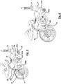
- a throttle body for supplying air to an internal combustion engine comprises, in a per se known manner, at least one duct 1 of the primary air flow regulated by a throttle valve F.
- Fig. 1 represents a variant that comprises a pair of side-by-side ducts 1 but, from the point of view of the invention, one or multiple ducts are equivalent.
- the throttle valve F of the primary air duct comprises a shutter plate or butterfly which is integral with a shaft A rotatably mounted in a direction transverse to the longitudinal axis of the duct 1.
- the two throttle valves have a single common driving shaft, so that their rotation can be controlled by a single driving device.
- the shutter of the throttle valve is able to rotate around its shaft to an angle of about 90°; that is, from a closed, or "almost” closed position, wherein the shutter plate is arranged almost transversely to the respective duct, to an open position, wherein the shutter plate is on a plane substantially aligned with the longitudinal axis of the duct.
- the closed position is defined as “almost closed” for the reason that, in fact, the shutter does not perfectly close the respective duct, but leaves a narrow free gap in order to prevent unwanted jams against the duct walls.
- the throttle valve controls the so-called primary air flow through a primary duct, but in modern throttle bodies there is also provided a bypass channel, external to the primary duct, wherein a secondary air flow is provided.
- the secondary air flow is defined and intended for the "idling" regimes of the engine, while the primary air flow is supplied to the engine in every other power condition.
- the secondary air flow is controlled by its own bypass valve 18, which is traditionally - as in the embodiment of Figs. 1-5B - in the form of a plug check valve P with a longitudinal displacement against spring means.
- This bypass valve although partially illustrated in the figures, will not be described in greater detail because it is known per se.
- the driving device being a single device, both for throttle valves F and for the bypass valve 18, comprises an electric motor 2 and a gear transmission with toothed-wheel gears.
- the drive motor is typically a DC motor or a stepper motor, housed within a case 3 of the throttle body and supported in cantilever fashion by a support plate 4.
- the gear transmission comprises a first pinion 5 keyed onto the end of the shaft of the motor 2, and at least one further intermediate idle gear to obtain a high reduction ratio of the transmission:
- the intermediate idle wheel comprises, for example, a first toothed wheel 6, which engages with the pinion 5, and a second pinion 7 coaxial and integral with the toothed wheel 6.
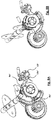
- the gear transmission further comprises a pair of toothed-sector elements 8 and 9, placed side by side on parallel planes and mounted coaxial to a shaft A of the throttle valve F.
- a first of said toothed sectors 8 is keyed on the shaft A of the throttle valve F and is therefore integral in rotation therewith: it constitutes the throttle valve driving element for the primary air control.
- a second of said toothed-sector elements 9 is mounted coaxial and freely rotatable on said shaft, but is dynamically associated to the first element 8, in the way better described in the following.
- the two toothed-sector elements 8, 9 are adjacent on parallel planes and have a width and a nominal diameter such that both can mesh with the second pinion 7 of the intermediate idle wheel. In other words, they are arranged so that they can take driving motion from the same gear. More precisely, the pinion 7 is in engagement at the same time with both toothings of the first and second toothed-sector elements 8, 9 for at least a central part of their travel.
- the toothings of the two toothed-sector elements 8, 9 are provided on two arcs of circle of different length.
- the teeth of the second toothed-sector element 9 are spread over an arc of circle much shorter than that of the first element 8, in proportion to the amplitude of rotation for which they must exercise their driving action.
- the teeth of the first element 8 are provided on a circle arc of the order of 90°, while the teeth of the second element 9 are provided on a circle arc of only 15°.
- the toothing of the first toothed sector element 8 is extending over an arc of circle of the order of 50-95°
- the toothing of the second toothed sector element 9 is extending over an arc of a circle of the order of 5-30°.
- the toothed-sector element can also be prolonged over a further arc of a circle other than that covered by the teeth, as is shown for a portion 9a of the second element 9.
- the first toothed-sector element 8 is keyed on the common shaft A of the two throttle valves F, so that its movements, controlled by the transmission gear through the pinion 7, drive the throttle valves towards the opening (counter-clockwise movement of the element 8) of the primary air duct 1, or respectively towards the closing (clockwise movement of the element 8).
- the first toothed-sector element 8 cooperates with a return elastic element, such as a spring 10, adapted to perform the function, well known per se, of bringing the throttle valve back towards a home position ( Fig. 2 ), that is, towards the closing position, ensuring the automatic closing of the throttle valve in the case of failure of the drive system.
- the end-of-travel home position, with the throttle valve F closed typically is resulting by a special abutment surface of the element 8 abutting on an appropriate end-of-travel element C fixed with respect to the throttle body case.
- the second toothed-sector element 9 is also mounted rotatably, but idle, on the axle of the common shaft A of the two throttle valves. In the home condition, the toothing of sector 9 meshes with the toothing of the drive pinion 7. As already mentioned above, the sector 9 is coupled dynamically to the first toothed-sector element 8 by the following method.
- the first element 8 has a driving peg 8b, projecting axially from the side facing the second toothed-sector element 9, which peg engages in an arched slot 9b formed in the second element 9: it determines a dragging effect in rotation between the two toothed-sector elements 8 and 9 when their relative rotation brings the peg 8b in abutment at the two opposite ends 9ba and 9bb of the slot 9b.
- the driving peg 8b can be replaced by any other suitable engaging means, for example the pin 8b' shown in the embodiment of fig. 8A .
- an elastic element 11 such as a spiral spring, which causes a torque that tends to rotate counter-clockwise the second element 9 with respect to the first 8, pushing the peg 8b in abutment against home end 9ba of the slot 9b ( Figs. 1 and 2 ).
- the two toothed-sector elements 8 and 9 When the peg 8b is in abutment to the home end 9ba of the slot 9b, the two toothed-sector elements 8 and 9 have at least one tooth mutually aligned (or almost aligned, with a very small phase shift, not exceeding a few tenths of a degree), so that a condition can occur wherein they are properly and simultaneously meshed with the corresponding teeth of the pinion 7.
- the teeth of the second toothed-sector element 9 extend beyond the end of the toothing of the first element 8, for an arc of a circle (of approximately 15°, as seen above) which determines the rotation useful to actuate the bypass valve 18, as will be described further below.
- This portion of the toothing of the second element 9, which extends beyond the ends of the toothing of the first element 8, is called the active portion of the toothing of the second element 9, as it is the one that determines the operational phase of the second toothed-sector element 9.
- the second toothed-sector element 9 also has a driving appendix which, in the first embodiment, is constituted by a portion of a toothed gear represented by a single tooth 9d; the latter is intended to cooperate with a tooth 12a of an opposite rocker lever 12, mounted free in rotation on a pin and intended to control a driven rod of the bypass valve 18 through an appendix 12b opposed to the tooth 12a.
- a driving appendix which, in the first embodiment, is constituted by a portion of a toothed gear represented by a single tooth 9d; the latter is intended to cooperate with a tooth 12a of an opposite rocker lever 12, mounted free in rotation on a pin and intended to control a driven rod of the bypass valve 18 through an appendix 12b opposed to the tooth 12a.
- the pair of toothed-sector elements 8 and 9 is mounted on the control shaft of the throttle valve so that in the home position, only the sector 9 meshes with the pinion toothing 7 and the appendix 9d is in engagement with the tooth 12a.
- the rotation of the tooth 9d is able to displace the rocker lever 12, against the action of a return spring, to an extent sufficient to correctly displace also the check plug P of the bypass valve 18.
- the back displacement is automatically performed by the return spring.
- Figs. 6A-10C show a second embodiment disclosing a different aspect of the invention.
- a driving appendix 9d' of a second toothed sector element 9' is in the shape of a proper toothed sector (including at least three teeth) meshing with a corresponding toothed sector 12a' acting as coupling means of a driving gear 12' for a bypass throttle valve 18'.
- the bypass throttle valve 18' comprises a rotating shutter plate attached to a shaft integral in rotation with driving gear 12'. This latter is biased by a torque spring 13' against an end-of travel abutment 14', toward a position wherein the bypass throttle valve 18' is open.
- the second toothed-sector element 9, 9' supports, in its centre of rotation, an internal magnetic button 13 (well visible in Fig. 2 ), which is intended to cooperate with a position sensor (not shown) external to the case of the throttle body, to provide an angular position signal of the system.
- control device described above is illustrated in the following making reference to the first embodiment, but it is intended that also an embodiment comprising a throttle bypass valve could have a similar operation.
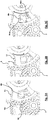
- Figs. 1 , 2 and 5A show a working position corresponding to the closed position of the throttle valves.
- this position - called “home” position as it corresponds to the end of the closing travel of the throttle valve - the first toothed-sector element 8 is biased in a clockwise direction, by the bias of the elastic element 10, against the end of travel C.
- the toothing of the first element 8 is disengaged (see end tooth 8c in Fig. 5A ) from the drive pinion 7, while the second element 9, biased by the spring 11 in such a way that the face 9ba of the slot is pressed against the abutment 8b, has its toothing at least in part meshed with the drive pinion 7.
- a counter-clockwise rotation of the pinion 7 causes the clockwise rotation of the second toothed-sector element 9, which is disengaged from the first element simply by overcoming the elastic reaction of the spring 11 ( Figs. 4 and 5C ).
- the relative rotation between the two is allowed because the driving peg 8b slides freely in the slot 9b, while the first element 8 remains stationary against the end of travel C ( Fig. 4 ).
- This phase of the counter-clockwise rotation of the pinion 7 thus allows to obtain, following the closure of the throttle of the primary air flow, a progressive actuation of the bypass valve by the rod of the plug valve P, which is also gradually closed obtaining the fine adjustment of the engine idling speed.
- the second toothed-sector element 9 follows the movement of the first element 8 due to the mutual coupling kept by the spring 11 (in the closing direction of the throttle) or by dragging due to the abutment 8b engaging the surface 9ba of the slot (in the opening direction of the throttle).
- the second toothed-sector element 9 is devoid of teeth on this rotation arc of the movement (as shown in the figures), to prevent that slight mismatching of the two elements 8 and 9 produce an offset of the toothed sectors that would ultimately cause jams or inaccurate measures of the angular position of the throttle valve.
- the device of the invention allows to fully achieve the purposes stated in the introduction.
- the construction of the drive mechanism is in fact simple and reliable; being based on gearings, it is also robust, reliable and requires low maintenance; thanks to the direct control on the throttle valve, it is possible to obtain a perfect control on the opening/closing of the primary air flow, also by virtue of the magnetic button 13 which provides an excellent detection capability of the displacement angle from the outside of the casing of the throttle body.
- the magnetic button 13 rotates integral with the element 9; furthermore, for the angular positions in which the pinion 7 meshes with the sector 8 only, the latter drags the sector 9 in rotation through the spring 11 or the abutment 8b: this allows, for each configuration, to uniquely detect, through the position sensor, the angular position of the throttle or that of the by-pass valve.
- the detectable element integral in rotation with drive shaft A can take other shapes than the magnetic button 13, but it still has the advantage of supplying a direct information of the angular position of the throttle valve.
Landscapes
- Engineering & Computer Science (AREA)
- Chemical & Material Sciences (AREA)
- Combustion & Propulsion (AREA)
- Mechanical Engineering (AREA)
- General Engineering & Computer Science (AREA)
- Control Of Throttle Valves Provided In The Intake System Or In The Exhaust System (AREA)
Applications Claiming Priority (1)
| Application Number | Priority Date | Filing Date | Title |
|---|---|---|---|
| ITUB2016A000567A ITUB20160567A1 (it) | 2016-02-08 | 2016-02-08 | Dispositivo di controllo del flusso d'aria in un corpo farfallato per l'alimentazione di un motore a combustione interna |
Publications (2)
| Publication Number | Publication Date |
|---|---|
| EP3203055A1 true EP3203055A1 (de) | 2017-08-09 |
| EP3203055B1 EP3203055B1 (de) | 2019-07-24 |
Family
ID=56097189
Family Applications (1)
| Application Number | Title | Priority Date | Filing Date |
|---|---|---|---|
| EP17155068.4A Active EP3203055B1 (de) | 2016-02-08 | 2017-02-07 | Vorrichtung zur steuerung des luftflusses in einem drosselklappenkörper zur versorgung einer brennkraftmaschine |
Country Status (2)
| Country | Link |
|---|---|
| EP (1) | EP3203055B1 (de) |
| IT (1) | ITUB20160567A1 (de) |
Cited By (5)
| Publication number | Priority date | Publication date | Assignee | Title |
|---|---|---|---|---|
| DE102018208685A1 (de) * | 2018-06-01 | 2019-03-21 | Bing Power Systems Gmbh | Ansaugvorrichtung für einen Verbrennungsmotor |
| JP2019127941A (ja) * | 2018-01-23 | 2019-08-01 | 株式会社ミクニ | スロットル装置 |
| DE102018213237A1 (de) * | 2018-08-07 | 2020-02-13 | Bayerische Motoren Werke Aktiengesellschaft | Sauganlage für eine Brennkraftmaschine |
| EP3800716A1 (de) * | 2019-10-03 | 2021-04-07 | Marelli Europe S.p.A. | Drosselklappe zur einstellung der zufuhr eines gases zu einer brennstoffzelle und elektrisch angetriebenes fahrzeug mit der drosselklappe |
| IT202100019985A1 (it) * | 2021-07-27 | 2023-01-27 | Denso Thermal Systems Spa | Cinematismo con settore dentato ribassato |
Citations (6)
| Publication number | Priority date | Publication date | Assignee | Title |
|---|---|---|---|---|
| DE4202406C1 (en) | 1992-01-29 | 1993-03-18 | Mercedes-Benz Aktiengesellschaft, 7000 Stuttgart, De | IC engine air intake control with two intake ducts - has each duct with throttle flap, one for medium and top load, and second for idling |
| JPH06167262A (ja) | 1992-11-30 | 1994-06-14 | Mazda Motor Corp | エンジンのアイドル調整弁制御装置 |
| US5657731A (en) | 1994-11-24 | 1997-08-19 | Hyundai Motor Company | Device for adjusting flow through an intake |
| EP1785615A1 (de) * | 2005-11-09 | 2007-05-16 | Keihin Corporation | Bypassvorrichtung in einem mehrfachen Drosselklappenkörper |
| DE102011076446A1 (de) | 2011-05-25 | 2012-11-29 | Bayerische Motoren Werke Aktiengesellschaft | Verfahren zum Steuern einer Ansaugeinrichtung eines Verbrennungsmotors sowie Ansaugeinrichtung für einen Verbrennungsmotor |
| DE102013006044A1 (de) | 2013-04-06 | 2014-10-09 | Bing Power Systems Gmbh | Ansaugvorrichtung für einen Verbrennungsmotor |
-
2016
- 2016-02-08 IT ITUB2016A000567A patent/ITUB20160567A1/it unknown
-
2017
- 2017-02-07 EP EP17155068.4A patent/EP3203055B1/de active Active
Patent Citations (6)
| Publication number | Priority date | Publication date | Assignee | Title |
|---|---|---|---|---|
| DE4202406C1 (en) | 1992-01-29 | 1993-03-18 | Mercedes-Benz Aktiengesellschaft, 7000 Stuttgart, De | IC engine air intake control with two intake ducts - has each duct with throttle flap, one for medium and top load, and second for idling |
| JPH06167262A (ja) | 1992-11-30 | 1994-06-14 | Mazda Motor Corp | エンジンのアイドル調整弁制御装置 |
| US5657731A (en) | 1994-11-24 | 1997-08-19 | Hyundai Motor Company | Device for adjusting flow through an intake |
| EP1785615A1 (de) * | 2005-11-09 | 2007-05-16 | Keihin Corporation | Bypassvorrichtung in einem mehrfachen Drosselklappenkörper |
| DE102011076446A1 (de) | 2011-05-25 | 2012-11-29 | Bayerische Motoren Werke Aktiengesellschaft | Verfahren zum Steuern einer Ansaugeinrichtung eines Verbrennungsmotors sowie Ansaugeinrichtung für einen Verbrennungsmotor |
| DE102013006044A1 (de) | 2013-04-06 | 2014-10-09 | Bing Power Systems Gmbh | Ansaugvorrichtung für einen Verbrennungsmotor |
Cited By (8)
| Publication number | Priority date | Publication date | Assignee | Title |
|---|---|---|---|---|
| JP2019127941A (ja) * | 2018-01-23 | 2019-08-01 | 株式会社ミクニ | スロットル装置 |
| DE102018208685A1 (de) * | 2018-06-01 | 2019-03-21 | Bing Power Systems Gmbh | Ansaugvorrichtung für einen Verbrennungsmotor |
| DE102018213237A1 (de) * | 2018-08-07 | 2020-02-13 | Bayerische Motoren Werke Aktiengesellschaft | Sauganlage für eine Brennkraftmaschine |
| DE102018213237B4 (de) | 2018-08-07 | 2024-05-02 | Bayerische Motoren Werke Aktiengesellschaft | Motorradbrennkraftmaschine mit innerer Verbrennung mit einer Motorradbrennkraftmaschinensauganlage und Verfahren zum Steuern einer solchen Motorradbrennkraftmaschinensauganlage |
| EP3800716A1 (de) * | 2019-10-03 | 2021-04-07 | Marelli Europe S.p.A. | Drosselklappe zur einstellung der zufuhr eines gases zu einer brennstoffzelle und elektrisch angetriebenes fahrzeug mit der drosselklappe |
| US11535109B2 (en) | 2019-10-03 | 2022-12-27 | Marelli Europe S.P.A. | Throttle valve for adjusting the feeding of a gas to a fuel cell and electric drive vehicle including the throttle valve |
| IT202100019985A1 (it) * | 2021-07-27 | 2023-01-27 | Denso Thermal Systems Spa | Cinematismo con settore dentato ribassato |
| EP4124777A1 (de) * | 2021-07-27 | 2023-02-01 | DENSO THERMAL SYSTEMS S.p.A. | Kinematischer mechanismus mit versenkte verzahnte sektor |
Also Published As
| Publication number | Publication date |
|---|---|
| EP3203055B1 (de) | 2019-07-24 |
| ITUB20160567A1 (it) | 2017-08-08 |
Similar Documents
| Publication | Publication Date | Title |
|---|---|---|
| EP3203055B1 (de) | Vorrichtung zur steuerung des luftflusses in einem drosselklappenkörper zur versorgung einer brennkraftmaschine | |
| US9689308B2 (en) | Throttle valve assembly | |
| US9927044B2 (en) | Dual shaft alternating drive actuator | |
| JP5521056B2 (ja) | 連結装置 | |
| US9745901B2 (en) | Valve comprising a movement transformation device | |
| EP2307682B1 (de) | Ventileinrichtung für eine brennkraftmaschine sowie brennkraftmaschine | |
| US10487925B2 (en) | Adjustment arrangement and valve control device comprising an adjustment arrangement | |
| KR20120092720A (ko) | 회전 운동을 병진 운동으로 전환하기 위한 장치 | |
| DE102006035391A1 (de) | Rotationslinearstellglied, Linearbewegungswellenmechanismus, variabler Ventilbetätigungsmechanismus und Motor mit variablem Ventil | |
| US20170152953A1 (en) | Double eccentric valve | |
| DE102005033601B4 (de) | Elektromechanische Stelleinrichtung für Abgasstauklappe | |
| CN101512175B (zh) | 自补偿调节的摩擦离合器 | |
| JP2015068573A5 (de) | ||
| US7775197B2 (en) | Engine sub-system actuators having variable ratio drive mechanisms | |
| JP6877253B2 (ja) | ガス弁装置 | |
| DE102008008893A1 (de) | Verfahren und System zum Einstellen eines Sensors für einen variablen Ventilmechanismus | |
| EP2577005A1 (de) | Stellvorrichtung für eine brennkraftmaschinenventiltriebvorrichtung | |
| US9587555B2 (en) | Transmission system and exhaust gas turbocharger | |
| RU56542U1 (ru) | Электропривод с ручным дублером поворотного затвора клапана, регулирующего давление в трубопроводе в автоматическом режиме | |
| US6089208A (en) | Throttle valve opening and closing apparatus for a vehicle, and vehicle internal combustion engine using the apparatus | |
| US4572932A (en) | Actuating mechanism | |
| DE4021691C2 (de) | Potentiometer | |
| CN106460680B (zh) | 流体流通阀 | |
| GB2119172A (en) | Actuating mechanism | |
| DE102010021784A1 (de) | Stellvorrichtung für eine Brennkraftmaschinenventiltriebvorrichtung |
Legal Events
| Date | Code | Title | Description |
|---|---|---|---|
| PUAI | Public reference made under article 153(3) epc to a published international application that has entered the european phase |
Free format text: ORIGINAL CODE: 0009012 |
|
| STAA | Information on the status of an ep patent application or granted ep patent |
Free format text: STATUS: THE APPLICATION HAS BEEN PUBLISHED |
|
| AK | Designated contracting states |
Kind code of ref document: A1 Designated state(s): AL AT BE BG CH CY CZ DE DK EE ES FI FR GB GR HR HU IE IS IT LI LT LU LV MC MK MT NL NO PL PT RO RS SE SI SK SM TR |
|
| AX | Request for extension of the european patent |
Extension state: BA ME |
|
| STAA | Information on the status of an ep patent application or granted ep patent |
Free format text: STATUS: REQUEST FOR EXAMINATION WAS MADE |
|
| 17P | Request for examination filed |
Effective date: 20180208 |
|
| RBV | Designated contracting states (corrected) |
Designated state(s): AL AT BE BG CH CY CZ DE DK EE ES FI FR GB GR HR HU IE IS IT LI LT LU LV MC MK MT NL NO PL PT RO RS SE SI SK SM TR |
|
| STAA | Information on the status of an ep patent application or granted ep patent |
Free format text: STATUS: EXAMINATION IS IN PROGRESS |
|
| 17Q | First examination report despatched |
Effective date: 20180628 |
|
| GRAP | Despatch of communication of intention to grant a patent |
Free format text: ORIGINAL CODE: EPIDOSNIGR1 |
|
| STAA | Information on the status of an ep patent application or granted ep patent |
Free format text: STATUS: GRANT OF PATENT IS INTENDED |
|
| INTG | Intention to grant announced |
Effective date: 20190328 |
|
| GRAS | Grant fee paid |
Free format text: ORIGINAL CODE: EPIDOSNIGR3 |
|
| GRAA | (expected) grant |
Free format text: ORIGINAL CODE: 0009210 |
|
| STAA | Information on the status of an ep patent application or granted ep patent |
Free format text: STATUS: THE PATENT HAS BEEN GRANTED |
|
| AK | Designated contracting states |
Kind code of ref document: B1 Designated state(s): AL AT BE BG CH CY CZ DE DK EE ES FI FR GB GR HR HU IE IS IT LI LT LU LV MC MK MT NL NO PL PT RO RS SE SI SK SM TR |
|
| REG | Reference to a national code |
Ref country code: GB Ref legal event code: FG4D |
|
| REG | Reference to a national code |
Ref country code: CH Ref legal event code: EP |
|
| REG | Reference to a national code |
Ref country code: DE Ref legal event code: R096 Ref document number: 602017005400 Country of ref document: DE |
|
| REG | Reference to a national code |
Ref country code: AT Ref legal event code: REF Ref document number: 1158478 Country of ref document: AT Kind code of ref document: T Effective date: 20190815 |
|
| REG | Reference to a national code |
Ref country code: IE Ref legal event code: FG4D |
|
| REG | Reference to a national code |
Ref country code: NL Ref legal event code: MP Effective date: 20190724 |
|
| REG | Reference to a national code |
Ref country code: LT Ref legal event code: MG4D |
|
| REG | Reference to a national code |
Ref country code: AT Ref legal event code: MK05 Ref document number: 1158478 Country of ref document: AT Kind code of ref document: T Effective date: 20190724 |
|
| PG25 | Lapsed in a contracting state [announced via postgrant information from national office to epo] |
Ref country code: LT Free format text: LAPSE BECAUSE OF FAILURE TO SUBMIT A TRANSLATION OF THE DESCRIPTION OR TO PAY THE FEE WITHIN THE PRESCRIBED TIME-LIMIT Effective date: 20190724 Ref country code: HR Free format text: LAPSE BECAUSE OF FAILURE TO SUBMIT A TRANSLATION OF THE DESCRIPTION OR TO PAY THE FEE WITHIN THE PRESCRIBED TIME-LIMIT Effective date: 20190724 Ref country code: PT Free format text: LAPSE BECAUSE OF FAILURE TO SUBMIT A TRANSLATION OF THE DESCRIPTION OR TO PAY THE FEE WITHIN THE PRESCRIBED TIME-LIMIT Effective date: 20191125 Ref country code: AT Free format text: LAPSE BECAUSE OF FAILURE TO SUBMIT A TRANSLATION OF THE DESCRIPTION OR TO PAY THE FEE WITHIN THE PRESCRIBED TIME-LIMIT Effective date: 20190724 Ref country code: NO Free format text: LAPSE BECAUSE OF FAILURE TO SUBMIT A TRANSLATION OF THE DESCRIPTION OR TO PAY THE FEE WITHIN THE PRESCRIBED TIME-LIMIT Effective date: 20191024 Ref country code: SE Free format text: LAPSE BECAUSE OF FAILURE TO SUBMIT A TRANSLATION OF THE DESCRIPTION OR TO PAY THE FEE WITHIN THE PRESCRIBED TIME-LIMIT Effective date: 20190724 Ref country code: FI Free format text: LAPSE BECAUSE OF FAILURE TO SUBMIT A TRANSLATION OF THE DESCRIPTION OR TO PAY THE FEE WITHIN THE PRESCRIBED TIME-LIMIT Effective date: 20190724 Ref country code: BG Free format text: LAPSE BECAUSE OF FAILURE TO SUBMIT A TRANSLATION OF THE DESCRIPTION OR TO PAY THE FEE WITHIN THE PRESCRIBED TIME-LIMIT Effective date: 20191024 Ref country code: NL Free format text: LAPSE BECAUSE OF FAILURE TO SUBMIT A TRANSLATION OF THE DESCRIPTION OR TO PAY THE FEE WITHIN THE PRESCRIBED TIME-LIMIT Effective date: 20190724 |
|
| PG25 | Lapsed in a contracting state [announced via postgrant information from national office to epo] |
Ref country code: RS Free format text: LAPSE BECAUSE OF FAILURE TO SUBMIT A TRANSLATION OF THE DESCRIPTION OR TO PAY THE FEE WITHIN THE PRESCRIBED TIME-LIMIT Effective date: 20190724 Ref country code: IS Free format text: LAPSE BECAUSE OF FAILURE TO SUBMIT A TRANSLATION OF THE DESCRIPTION OR TO PAY THE FEE WITHIN THE PRESCRIBED TIME-LIMIT Effective date: 20191124 Ref country code: GR Free format text: LAPSE BECAUSE OF FAILURE TO SUBMIT A TRANSLATION OF THE DESCRIPTION OR TO PAY THE FEE WITHIN THE PRESCRIBED TIME-LIMIT Effective date: 20191025 Ref country code: AL Free format text: LAPSE BECAUSE OF FAILURE TO SUBMIT A TRANSLATION OF THE DESCRIPTION OR TO PAY THE FEE WITHIN THE PRESCRIBED TIME-LIMIT Effective date: 20190724 Ref country code: LV Free format text: LAPSE BECAUSE OF FAILURE TO SUBMIT A TRANSLATION OF THE DESCRIPTION OR TO PAY THE FEE WITHIN THE PRESCRIBED TIME-LIMIT Effective date: 20190724 Ref country code: ES Free format text: LAPSE BECAUSE OF FAILURE TO SUBMIT A TRANSLATION OF THE DESCRIPTION OR TO PAY THE FEE WITHIN THE PRESCRIBED TIME-LIMIT Effective date: 20190724 |
|
| PG25 | Lapsed in a contracting state [announced via postgrant information from national office to epo] |
Ref country code: TR Free format text: LAPSE BECAUSE OF FAILURE TO SUBMIT A TRANSLATION OF THE DESCRIPTION OR TO PAY THE FEE WITHIN THE PRESCRIBED TIME-LIMIT Effective date: 20190724 |
|
| PG25 | Lapsed in a contracting state [announced via postgrant information from national office to epo] |
Ref country code: DK Free format text: LAPSE BECAUSE OF FAILURE TO SUBMIT A TRANSLATION OF THE DESCRIPTION OR TO PAY THE FEE WITHIN THE PRESCRIBED TIME-LIMIT Effective date: 20190724 Ref country code: PL Free format text: LAPSE BECAUSE OF FAILURE TO SUBMIT A TRANSLATION OF THE DESCRIPTION OR TO PAY THE FEE WITHIN THE PRESCRIBED TIME-LIMIT Effective date: 20190724 Ref country code: RO Free format text: LAPSE BECAUSE OF FAILURE TO SUBMIT A TRANSLATION OF THE DESCRIPTION OR TO PAY THE FEE WITHIN THE PRESCRIBED TIME-LIMIT Effective date: 20190724 Ref country code: EE Free format text: LAPSE BECAUSE OF FAILURE TO SUBMIT A TRANSLATION OF THE DESCRIPTION OR TO PAY THE FEE WITHIN THE PRESCRIBED TIME-LIMIT Effective date: 20190724 |
|
| PG25 | Lapsed in a contracting state [announced via postgrant information from national office to epo] |
Ref country code: IS Free format text: LAPSE BECAUSE OF FAILURE TO SUBMIT A TRANSLATION OF THE DESCRIPTION OR TO PAY THE FEE WITHIN THE PRESCRIBED TIME-LIMIT Effective date: 20200224 Ref country code: SM Free format text: LAPSE BECAUSE OF FAILURE TO SUBMIT A TRANSLATION OF THE DESCRIPTION OR TO PAY THE FEE WITHIN THE PRESCRIBED TIME-LIMIT Effective date: 20190724 Ref country code: CZ Free format text: LAPSE BECAUSE OF FAILURE TO SUBMIT A TRANSLATION OF THE DESCRIPTION OR TO PAY THE FEE WITHIN THE PRESCRIBED TIME-LIMIT Effective date: 20190724 Ref country code: SK Free format text: LAPSE BECAUSE OF FAILURE TO SUBMIT A TRANSLATION OF THE DESCRIPTION OR TO PAY THE FEE WITHIN THE PRESCRIBED TIME-LIMIT Effective date: 20190724 |
|
| REG | Reference to a national code |
Ref country code: DE Ref legal event code: R097 Ref document number: 602017005400 Country of ref document: DE |
|
| PLBE | No opposition filed within time limit |
Free format text: ORIGINAL CODE: 0009261 |
|
| STAA | Information on the status of an ep patent application or granted ep patent |
Free format text: STATUS: NO OPPOSITION FILED WITHIN TIME LIMIT |
|
| PG2D | Information on lapse in contracting state deleted |
Ref country code: IS |
|
| 26N | No opposition filed |
Effective date: 20200603 |
|
| PG25 | Lapsed in a contracting state [announced via postgrant information from national office to epo] |
Ref country code: SI Free format text: LAPSE BECAUSE OF FAILURE TO SUBMIT A TRANSLATION OF THE DESCRIPTION OR TO PAY THE FEE WITHIN THE PRESCRIBED TIME-LIMIT Effective date: 20190724 |
|
| REG | Reference to a national code |
Ref country code: CH Ref legal event code: PL |
|
| REG | Reference to a national code |
Ref country code: BE Ref legal event code: MM Effective date: 20200229 |
|
| PG25 | Lapsed in a contracting state [announced via postgrant information from national office to epo] |
Ref country code: MC Free format text: LAPSE BECAUSE OF FAILURE TO SUBMIT A TRANSLATION OF THE DESCRIPTION OR TO PAY THE FEE WITHIN THE PRESCRIBED TIME-LIMIT Effective date: 20190724 Ref country code: LU Free format text: LAPSE BECAUSE OF NON-PAYMENT OF DUE FEES Effective date: 20200207 |
|
| PG25 | Lapsed in a contracting state [announced via postgrant information from national office to epo] |
Ref country code: CH Free format text: LAPSE BECAUSE OF NON-PAYMENT OF DUE FEES Effective date: 20200229 Ref country code: LI Free format text: LAPSE BECAUSE OF NON-PAYMENT OF DUE FEES Effective date: 20200229 |
|
| PG25 | Lapsed in a contracting state [announced via postgrant information from national office to epo] |
Ref country code: FR Free format text: LAPSE BECAUSE OF NON-PAYMENT OF DUE FEES Effective date: 20200229 Ref country code: IE Free format text: LAPSE BECAUSE OF NON-PAYMENT OF DUE FEES Effective date: 20200207 |
|
| PG25 | Lapsed in a contracting state [announced via postgrant information from national office to epo] |
Ref country code: BE Free format text: LAPSE BECAUSE OF NON-PAYMENT OF DUE FEES Effective date: 20200229 |
|
| GBPC | Gb: european patent ceased through non-payment of renewal fee |
Effective date: 20210207 |
|
| PG25 | Lapsed in a contracting state [announced via postgrant information from national office to epo] |
Ref country code: GB Free format text: LAPSE BECAUSE OF NON-PAYMENT OF DUE FEES Effective date: 20210207 |
|
| PG25 | Lapsed in a contracting state [announced via postgrant information from national office to epo] |
Ref country code: MT Free format text: LAPSE BECAUSE OF FAILURE TO SUBMIT A TRANSLATION OF THE DESCRIPTION OR TO PAY THE FEE WITHIN THE PRESCRIBED TIME-LIMIT Effective date: 20190724 Ref country code: CY Free format text: LAPSE BECAUSE OF FAILURE TO SUBMIT A TRANSLATION OF THE DESCRIPTION OR TO PAY THE FEE WITHIN THE PRESCRIBED TIME-LIMIT Effective date: 20190724 |
|
| PG25 | Lapsed in a contracting state [announced via postgrant information from national office to epo] |
Ref country code: MK Free format text: LAPSE BECAUSE OF FAILURE TO SUBMIT A TRANSLATION OF THE DESCRIPTION OR TO PAY THE FEE WITHIN THE PRESCRIBED TIME-LIMIT Effective date: 20190724 |
|
| PGFP | Annual fee paid to national office [announced via postgrant information from national office to epo] |
Ref country code: IT Payment date: 20230118 Year of fee payment: 7 |
|
| P01 | Opt-out of the competence of the unified patent court (upc) registered |
Effective date: 20230516 |
|
| PGFP | Annual fee paid to national office [announced via postgrant information from national office to epo] |
Ref country code: DE Payment date: 20240116 Year of fee payment: 8 |