EP3203004A1 - Scherenlager eines dreh-kipp-beschlages - Google Patents
Scherenlager eines dreh-kipp-beschlages Download PDFInfo
- Publication number
- EP3203004A1 EP3203004A1 EP17150521.7A EP17150521A EP3203004A1 EP 3203004 A1 EP3203004 A1 EP 3203004A1 EP 17150521 A EP17150521 A EP 17150521A EP 3203004 A1 EP3203004 A1 EP 3203004A1
- Authority
- EP
- European Patent Office
- Prior art keywords
- scissor
- hinge pin
- wing
- bearing according
- arm
- Prior art date
- Legal status (The legal status is an assumption and is not a legal conclusion. Google has not performed a legal analysis and makes no representation as to the accuracy of the status listed.)
- Granted
Links
Images


Classifications
-
- E—FIXED CONSTRUCTIONS
- E05—LOCKS; KEYS; WINDOW OR DOOR FITTINGS; SAFES
- E05D—HINGES OR SUSPENSION DEVICES FOR DOORS, WINDOWS OR WINGS
- E05D15/00—Suspension arrangements for wings
- E05D15/28—Suspension arrangements for wings supported on arms movable in horizontal plane
- E05D15/30—Suspension arrangements for wings supported on arms movable in horizontal plane with pivoted arms and sliding guides
-
- E—FIXED CONSTRUCTIONS
- E05—LOCKS; KEYS; WINDOW OR DOOR FITTINGS; SAFES
- E05D—HINGES OR SUSPENSION DEVICES FOR DOORS, WINDOWS OR WINGS
- E05D15/00—Suspension arrangements for wings
- E05D15/48—Suspension arrangements for wings allowing alternative movements
- E05D15/52—Suspension arrangements for wings allowing alternative movements for opening about a vertical as well as a horizontal axis
- E05D15/5205—Suspension arrangements for wings allowing alternative movements for opening about a vertical as well as a horizontal axis with horizontally-extending checks
-
- E—FIXED CONSTRUCTIONS
- E05—LOCKS; KEYS; WINDOW OR DOOR FITTINGS; SAFES
- E05Y—INDEXING SCHEME ASSOCIATED WITH SUBCLASSES E05D AND E05F, RELATING TO CONSTRUCTION ELEMENTS, ELECTRIC CONTROL, POWER SUPPLY, POWER SIGNAL OR TRANSMISSION, USER INTERFACES, MOUNTING OR COUPLING, DETAILS, ACCESSORIES, AUXILIARY OPERATIONS NOT OTHERWISE PROVIDED FOR, APPLICATION THEREOF
- E05Y2600/00—Mounting or coupling arrangements for elements provided for in this subclass
- E05Y2600/50—Mounting methods; Positioning
- E05Y2600/52—Toolless
- E05Y2600/528—Hooking, e.g. using bayonets; Locking
-
- E—FIXED CONSTRUCTIONS
- E05—LOCKS; KEYS; WINDOW OR DOOR FITTINGS; SAFES
- E05Y—INDEXING SCHEME ASSOCIATED WITH SUBCLASSES E05D AND E05F, RELATING TO CONSTRUCTION ELEMENTS, ELECTRIC CONTROL, POWER SUPPLY, POWER SIGNAL OR TRANSMISSION, USER INTERFACES, MOUNTING OR COUPLING, DETAILS, ACCESSORIES, AUXILIARY OPERATIONS NOT OTHERWISE PROVIDED FOR, APPLICATION THEREOF
- E05Y2600/00—Mounting or coupling arrangements for elements provided for in this subclass
- E05Y2600/50—Mounting methods; Positioning
- E05Y2600/52—Toolless
- E05Y2600/53—Snapping
-
- E—FIXED CONSTRUCTIONS
- E05—LOCKS; KEYS; WINDOW OR DOOR FITTINGS; SAFES
- E05Y—INDEXING SCHEME ASSOCIATED WITH SUBCLASSES E05D AND E05F, RELATING TO CONSTRUCTION ELEMENTS, ELECTRIC CONTROL, POWER SUPPLY, POWER SIGNAL OR TRANSMISSION, USER INTERFACES, MOUNTING OR COUPLING, DETAILS, ACCESSORIES, AUXILIARY OPERATIONS NOT OTHERWISE PROVIDED FOR, APPLICATION THEREOF
- E05Y2600/00—Mounting or coupling arrangements for elements provided for in this subclass
- E05Y2600/50—Mounting methods; Positioning
- E05Y2600/56—Positioning, e.g. re-positioning, or pre-mounting
Definitions
- the invention relates to a scissor bearing of a turn-tilt fitting for a against a frame rotatable and tiltable wing of a window, a French window or the like, with a frame-side fitting part and a wing-side fitting part, with a mounted on both fitting parts scissor arm, and with a in the scissor arm and one of the fittings mounted handlebar.
- a Ausstellvorrhythmettidron for a tilt-swivel wing is for example from the DE 2 044 189 A known.
- hinge pins are provided with a tip and are introduced from above into a corresponding receptacle of the adjacent component.
- the hinge pins are arranged on the scissor arm and the receptacles on the wing-side fitting part and the link arm.
- a disadvantage of the known scissor bearing however, that especially for large and heavy wings, the assembly is very difficult.
- the wing is to be held in an intended position during the joining of the hinge pins. Subsequently, another fitter from above the hinge pins in the recordings introduce. The wing must be kept in a certain position, because only then fit the hinge pin in the recordings. This is very complex.
- a storage device for a window has become known, in which a scissor arm and a link arm on the frame-side fitting part are pre-assembled.
- the scissor arm and the link arm each have hinge pins, with which they are pressed from above into the wing-side fitting part.
- the wing must be held during assembly in a predetermined position when the hinge pins are pressed into the appropriate recordings. This is very complex.
- the invention is based on the problem of further forming a scissors bearing of the type mentioned above so that it is particularly easy to assemble and has a simple structure.
- the fittings can be individually mounted on the wing and the frame.
- the scissors bearing only requires the components required for the function and is therefore particularly simple.
- This assembly takes place in the frame turned away or weggekippten state of the wing.
- the locking connections for locking in the movement of the wing are formed in the closed position in the frame.
- the latching connections engage and connect the arms with each other and with both fitting parts of the scissor bearing. Since the joining direction coincides with the movement of the wing in the closed position, the assembly of the scissor bearing can also be automated. As a result, the assembly is particularly simple.
- the latching connections are structurally particularly simple according to another advantageous development of the invention, when the scissor arm with the one fitting part as a first preassembled assembly and the link arm with the other fitting part as a second preassembled module are formed when the assemblies connecting hinge pin and the hinge pin bearing recordings are formed as part of a respective latching connection.
- Another advantage of this design is that only components are used for the locking connections, which are necessary anyway for the function of the shear bearing.
- the scissor bearing can therefore be produced particularly cost-effectively.
- the assembly of the scissors bearing can be easily controlled according to another advantageous embodiment of the invention by a single glance at the scissor arm, when the hinge pins are arranged in the scissor arm.
- the mounting of the scissors bearing designed according to another advantageous embodiment of the invention is particularly simple if each run-on bevels are arranged on the recordings for guiding the hinge pin at the junction of the latching connections.
- the components having the receptacles preferably have a broadening in the region of the ramps, so that the ramps can be provided with a slight pitch.
- the forces for mounting the scissors bearing can be kept particularly low if the ramps near the receptacles have a smaller pitch than in a region remote from the receptacle. Since the pressure of the hinge pin on the ramp increases with increasing height of rise, thereby the force to be applied for the assembly is reduced.
- the ramps have the shape of tapered to the receptacles grooves.
- the channel shape ensures safe guidance of the hinge pin.
- the taper to the recordings ensures that even with tolerance deviations of the two fitting parts, the hinge pins are reliably guided during assembly to their recordings.
- the scissor bearing has, according to another advantageous embodiment of the invention, a particularly high stability, when the chamfers are manufactured as stampings of flat material.
- the ramps are formed in the manner of stiffening beads of the sheet.
- the hinge pin has a locking head, which can be inserted in a mounting position in the receiving component having and in a locking position engages behind the receptacle.
- the locking connection can easily snap when the locking head is in the mounting position. Subsequently, the locking head is moved into the locking position and secures the hinge pin against falling out of the receptacle.
- the locking head has a spherical contact surface with respect to the receptacle, so that a friction is kept low.
- the locking head designed in accordance with another advantageous embodiment of the invention structurally particularly simple when the hinge pin is rotatable when the locking head has a arranged on the free end of the hinge pin cross bar and when the hinge pin receiving receptacle is formed as a slot, wherein the crossbar in the one rotational position of the hinge pin inserted into the receptacle and engages behind the receptacle in the other rotational position of the hinge pin.
- a backup of the locking position of the locking head is particularly simple according to another advantageous embodiment of the invention, when the rotatable hinge pin rotatably connected to a locking plate and when the locking plate is locked in the locking position of the locking head with the scissor arm.
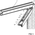
- FIG. 1 shows an upper right corner portion of a window with a pivotable against a frame 1 wings 2 and with a scissor bearing 3.
- the window is in a rotational position in which the wing 2 is rotated about a vertical axis from the frame 1.
- the window in this embodiment has a concealed handlebar arrangement 4th
- the scissors-type bearing 3 has a scissor arm 5 arranged parallel to the wing 2 in the rotary position.
- the scissor arm 5 is mounted on the handlebar arrangement 4 and has a bearing 6 on a wing-side fitting part 7.
- a handlebar arm 8 mounted in the wing-side fitting part 7 has a bearing 9 on the scissor arm 5.
- the scissor bearing 3 serves to move the wing 2 of the frame 1 in a tilted about a horizontal axis tilted position.
- FIG. 2 shows the scissors bearing 3 before mounting.
- the scissors bearing 3 has a frame-side fitting part 10 facing the wing-side fitting part 7.
- the frame-side fitting part 10 has a frame-side base plate 11 for mounting the link assembly 4.
- the wing-side fitting part 7 has a wing-side base plate 12.
- the wing-side fitting part 7 has an adjusting device 13 for adjusting the position of in FIG. 1 illustrated bearing 9 of the link arm 8 on the wing-side base plate 12.
- the components of the scissor bearing 3 are for clarity in FIG. 3 in one of FIG. 2 seen from the opposite side.
- the link arm 8 and the wing-side base plate 12 have receptacles 16, 17 for the hinge pins 14, 15.
- the arranged in the base plate 12 receptacle 16 for the storage 6 of the scissor arm 5 is formed as a slot and allows a slide along the guided therein hinge pin fourteenth
- the bearings of the scissor arm 5 on the link arm 8 and on the wing-side base plate 12 each have a latching connection 18, 19.
- the joining direction of the snap-in connections 18, 19 extends in the closing direction of the wing 2 and thus in the direction in which the wing 2 in the frame 1 is movable.
- the wing-side base plate 12 and the link arm 8 have on the receptacles 16, 17 channel-shaped ramps 20, 21.
- the link arm 8 also has for the ramps 20, 21 a broadening 22.
- the hinge pin 14 supporting the free end of the scissor arm 5 on the wing-side base plate 12 is rotatably arranged in the scissor arm 5 and connected in a rotationally fixed manner to a securing plate 23.
- this hinge pin 14 has a locking head 24 with a transverse web 25.
- the transverse web 25 is aligned parallel to the receptacle 16 formed as a slot and can thus be introduced into the receptacle 16 when joining the locking connection 18.
- the locking plate 23 has the scissor arm 5 facing latching hooks 26, 26 '.
- FIG. 4 shows an enlarged perspective view of the bearings 6, 9 of the scissor arm 5 on the wing-side base plate 12 and the link arm 8.
- the locking head 24 of the arranged at the free end of the scissors arm 5 pivot pin 14 is opposite to in the FIGS. 2 and 3 rotated position shown so that the cross bar 25 engages behind the receptacle 16 in the wing-side base plate 12.
- By the rotation is also the locking plate 23 in a direction parallel to the scissor arm 5 position.
- the locking hooks 26, 26 'of the locking plate 23 engage around the scissor arm 5 and thus secure this hinge pin 14 against rotation.
- FIG. 5 shows in a sectional view through the bearing 9 of the scissor arm 5 on the link arm 8 that the ramp 21 near the receptacle 17 has a lower slope than in a remote from the receptacle 17 area.
Landscapes
- Engineering & Computer Science (AREA)
- Mechanical Engineering (AREA)
- Hinges (AREA)
Abstract
Description
- Die Erfindung betrifft ein Scherenlager eines Dreh-Kipp-Beschlages für einen gegen einen Rahmen dreh- und kippbaren Flügel eines Fensters, einer Fenstertür oder dergleichen, mit einem rahmenseitigen Beschlagteil und einem flügelseitigen Beschlagteil, mit einem an beiden Beschlagteilen gelagerten Scherenarm, und mit einem in dem Scherenarm und einem der Beschlagteile gelagerten Lenkerarm.
- Eine Ausstellvorrichtung für einen Kipp-Schwenkflügel ist beispielsweise aus der
DE 2 044 189 A bekannt. Bei diesem Scherenlager sind Gelenkbolzen mit einer Spitze versehen und werden von oben in eine entsprechende Aufnahme des angrenzenden Bauteils eingeführt. Die Gelenkbolzen sind an dem Scherenarm angeordnet und die Aufnahmen an dem flügelseitigen Beschlagteil und dem Lenkerarm. Nachteilig bei dem bekannten Scherenlager ist jedoch, dass sich insbesondere bei großen und schweren Flügeln die Montage sehr schwierig bereitet. Der Flügel ist während des Fügens der Gelenkbolzen in einer vorgesehenen Lage zu halten. Anschließend kann ein weiterer Monteur von oben die Gelenkbolzen in die Aufnahmen einführen. Der Flügel muss dabei in einer bestimmten Position gehalten werden, weil nur dann die Gelenkbolzen in die Aufnahmen passen. Dies gestaltet sich sehr aufwändig. - Aus der
EP 1 612 354 A2 ist eine Lagereinrichtung für ein Fenster bekannt geworden, bei dem ein Scherenarm und ein Lenkerarm am rahmenseitigen Beschlagteil vormontiert werden. Der Scherenarm und der Lenkerarm weisen jeweils Gelenkbolzen auf, mit denen sie von oben in das flügelseitige Beschlagteil eingedrückt werden. Damit muss der Flügel bei der Montage in einer vorgesehenen Position gehalten werden, wenn die Gelenkbolzen in dafür vorgesehene Aufnahmen gedrückt werden. Dies gestaltet sich sehr aufwändig. - Aus der
EP 2 395 189 A2 ist ein oberes Lager für einen gegen einen Rahmen schwenkbaren Flügel bekannt geworden, bei dem ein Beschlagteil zweiteilig gestaltet ist. Ein Teil wird mit den übrigen Bauteilen des gesamten Lagers vormontiert. Die Endmontage erfolgt dann durch Fügen des zweiteiligen Beschlagteils. Hierdurch weist das Lager sehr viele Bauteile auf. Die Montage der einzelnen Bauteile ist aufwändig. - Der Erfindung liegt das Problem zugrunde, ein Scherenlager der eingangs genannten Art so weiter zu bilden, dass es besonders einfach montierbar ist und einfach aufgebaut ist.
- Dieses Problem wird erfindungsgemäß dadurch gelöst, dass Verbindungen des Scherenarms mit einem der Beschlagteile Rastverbindungen aufweisen und dass die jeweiligen Fügerichtungen der Rastverbindungen und eine Schließrichtung des Flügels gegen den Rahmen fluchten.
- Durch diese Gestaltung lassen sich die Beschlagteile einzeln an dem Flügel und dem Rahmen montieren. Das Scherenlager benötigt nur die zur Funktion erforderlichen Bauteile und ist damit besonders einfach aufgebaut. Diese Montage erfolgt im von dem Rahmen weggedrehten oder weggekippten Zustand des Flügels. Durch ihre Fügerichtung sind die Rastverbindungen zur Verrastung bei der Bewegung des Flügels in die im Rahmen liegende Schließstellung ausgebildet. Bei der anschließenden Bewegung des Flügels von der Kippstellung oder der Drehstellung gegen den Rahmen in die Schließstellung rasten die Rastverbindungen ein und verbinden die Arme untereinander und mit beiden Beschlagteilen des Scherenlagers. Da die Fügerichtung mit der Bewegung des Flügels in die Schließstellung zusammenfällt, lässt sich die Montage des Scherenlagers zudem automatisieren. Hierdurch gestaltet sich die Montage besonders einfach.
- Die Rastverbindungen gestalten sich gemäß einer anderen vorteilhaften Weiterbildung der Erfindung konstruktiv besonders einfach, wenn der Scherenarm mit dem einen Beschlagteil als erste vormontierbare Baugruppe und der Lenkerarm mit dem anderem Beschlagteil als zweite vormontierbare Baugruppe ausgebildet sind, wenn die Baugruppen verbindenden Gelenkbolzen und die Gelenkbolzen lagernden Aufnahmen als Teil jeweils einer Rastverbindung ausgebildet sind. Ein weiterer Vorteil dieser Gestaltung besteht darin, dass für die Rastverbindungen nur Bauteile verwendet werden, die für die Funktion des Scherenlagers ohnehin notwendig sind. Damit lässt sich das Scherenlager zudem besonders kostengünstig fertigen.
- Die Montage des Scherenlagers lässt sich gemäß einer anderen vorteilhaften Weiterbildung der Erfindung durch einen einzigen Blick auf den Scherenarm einfach kontrollieren, wenn die Gelenkbolzen in dem Scherenarm angeordnet sind.
- Die Montage des Scherenlagers gestaltet sich gemäß einer anderen vorteilhaften Weiterbildung der Erfindung besonders einfach, wenn an den Aufnahmen zur Führung der Gelenkbolzen bei der Fügung der Rastverbindungen jeweils Auflaufschrägen angeordnet sind. Vorzugsweise weisen die die Aufnahmen aufweisende Bauteile im Bereich der Auflaufschrägen eine Verbreiterung auf, so dass die Auflaufschrägen mit einer geringen Steigung versehen werden können.
- Die Kräfte zur Montage des Scherenlagers lassen sich gemäß einer anderen vorteilhaften Weiterbildung der Erfindung besonders gering halten, wenn die Auflaufschrägen nahe der Aufnahmen eine geringere Steigung aufweisen als in einem von der Aufnahme entfernten Bereich. Da der Druck des Gelenkbolzens auf die Auflaufschräge mit zunehmender Steighöhe ansteigt, wird hierdurch die für die Montage aufzubringende Kraft verringert.
- Zur weiteren Vereinfachung der Montage des Scherenlagers trägt es gemäß einer anderen vorteilhaften Weiterbildung der Erfindung bei, wenn die Auflaufschrägen die Form von sich zu den Aufnahmen verjüngenden Rinnen aufweisen. Die Rinnenform gewährleistet eine sichere Führung der Gelenkbolzen. Die Verjüngung zu den Aufnahmen stellt sicher, dass auch bei Toleranzabweichungen der beiden Beschlagteile die Gelenkbolzen bei der Montage zuverlässig zu ihren Aufnahmen geführt werden.
- Das Scherenlager weist gemäß einer anderen vorteilhaften Weiterbildung der Erfindung eine besonders hohe Stabilität auf, wenn die Auflaufschrägen als Verprägungen von Flachmaterial gefertigt sind. Damit sind die Auflaufschrägen nach Art von Versteifungssicken des Flachmaterials ausgebildet.
- Ein versehentliches Lösen der Rastverbindungen lässt sich gemäß einer anderen vorteilhaften Weiterbildung der Erfindung einfach vermeiden, wenn zumindest einer der Gelenkbolzen einen Arretierkopf aufweist, welcher in einer Montagestellung in das die Aufnahme aufweisende Bauteil eingeführt werden kann und in einer Arretierstellung die Aufnahme hintergreift. Durch diese Gestaltung vermag die Rastverbindung einfach einzuschnappen, wenn sich der Arretierkopf in der Montagestellung befindet. Anschließend wird der Arretierkopf in die Arretierstellung bewegt und sichert den Gelenkbolzen gegen ein Herausfallen aus der Aufnahme. Vorzugsweise hat der Arretierkopf eine kugelförmige Kontaktfläche gegenüber der Aufnahme, so dass eine Reibung gering gehalten ist.
- Der Arretierkopf gestaltet sich gemäß einer anderen vorteilhaften Weiterbildung der Erfindung konstruktiv besonders einfach, wenn der Gelenkbolzen drehbar ist, wenn der Arretierkopf einen auf dem freien Ende des Gelenkbolzen angeordneten Quersteg hat und wenn die den Gelenkbolzen aufnehmende Aufnahme als Langloch ausgebildet ist, wobei der Quersteg in der einen Drehstellung des Gelenkbolzens in die Aufnahme einführbar und in der anderen Drehstellung des Gelenkbolzens die Aufnahme hintergreift.
- Eine Sicherung der Arretierstellung des Arretierkopfes gestaltet sich gemäß einer anderen vorteilhaften Weiterbildung der Erfindung besonders einfach, wenn der drehbare Gelenkbolzen drehfest mit einem Sicherungsblech verbunden ist und wenn das Sicherungsblech in der Arretierstellung des Arretierkopfes mit dem Scherenarm verrastet ist.
- Die Erfindung lässt zahlreiche Ausführungsformen zu. Zur weiteren Verdeutlichung ihres Grundprinzips ist eine davon in der Zeichnung dargestellt und wird nachfolgend beschrieben. Diese zeigt in
- Fig. 1
- perspektivisch ein Fenster mit einem Scherenlager in Drehstellung,
- Fig. 2
- Bauteile des Scherenlagers aus
Figur 1 vor der Montage in einer Ansicht von oben, - Fig. 3
- Bauteile des Scherenlagers aus
Figur 1 vor der Montage in einer Ansicht von unten, - Fig. 4
- stark vergrößert eine perspektivische Darstellung eines Teilbereichs des Scherenlagers nach der Montage,
- Fig. 5
- eine Schnittdarstellung durch das Scherenlager aus Figur 4 entlang der Linie V - V.
-
Figur 1 zeigt einen oberen rechten Eckbereich eines Fensters mit einem gegen einen Rahmen 1 schwenkbaren Flügel 2 und mit einem Scherenlager 3. Das Fenster befindet sich in einer Drehstellung, in der der Flügel 2 um eine vertikale Achse von dem Rahmen 1 weggedreht ist. Für diese Drehbewegung hat das Fenster in diesem Ausführungsbeispiel eine verdeckt angeordnete Lenkeranordnung 4. - Das Scherenlager 3 hat einen in der Drehstellung parallel zum Flügel 2 angeordneten Scherenarm 5. Der Scherenarm 5 ist an der Lenkeranordnung 4 gelagert und hat eine Lagerung 6 an einem flügelseitigen Beschlagteil 7. Weiterhin hat ein in dem flügelseitigen Beschlagteil 7 gelagerter Lenkerarm 8 eine Lagerung 9 an dem Scherenarm 5. Das Scherenlager 3 dient dazu, den Flügel 2 von dem Rahmen 1 in eine um eine horizontale Achse weggekippte Kippstellung zu bewegen.
-
Figur 2 zeigt das Scherenlager 3 vor der Montage. Hierbei ist zu erkennen, dass das Scherenlager 3 ein dem flügelseitigen Beschlagteil 7 gegenüberstehendes rahmenseitiges Beschlagteil 10 hat. Das rahmenseitige Beschlagteil 10 hat eine rahmenseitige Grundplatte 11 zur Lagerung der Lenkeranordnung 4. Das flügelseitige Beschlagteil 7 hat eine flügelseitige Grundplatte 12. Weiterhin hat das flügelseitige Beschlagteil 7 eine Justiervorrichtung 13 zur Einstellung der Position der inFigur 1 dargestellten Lagerung 9 des Lenkerarms 8 an der flügelseitigen Grundplatte 12. Die Bauteile des Scherenlagers 3 sind zur Verdeutlichung inFigur 3 in einer vonFigur 2 aus gesehen gegenüberliegenden Seite dargestellt. - Die in
Figur 1 dargestellten Lagerungen 6, 9 des Scherenarms 5 an dem Lenkerarm 8 und an der flügelseitigen Grundplatte 12 weisen jeweils einen in dem Scherenarm 5 angeordneten Gelenkbolzen 14, 15 auf. Der Lenkerarm 8 und die flügelseitige Grundplatte 12 weisen Aufnahmen 16, 17 für die Gelenkbolzen 14, 15 auf. Die in der Grundplatte 12 angeordnete Aufnahme 16 für die Lagerung 6 des Scherenarms 5 ist als Langloch ausgebildet und ermöglicht ein entlang gleiten des darin geführten Gelenkbolzens 14. - Die Lagerungen des Scherenarms 5 an dem Lenkerarm 8 und an der flügelseitigen Grundplatte 12 weisen jeweils eine Rastverbindung 18, 19 auf. Die Fügerichtung der Rastverbindungen 18, 19 verläuft in Schließrichtung des Flügels 2 und damit in die Richtung, in die der Flügel 2 in den Rahmen 1 bewegbar ist. Die flügelseitige Grundplatte 12 und der Lenkerarm 8 haben an den Aufnahmen 16, 17 rinnenförmige Auflaufschrägen 20, 21. Der Lenkerarm 8 weist zudem für die Auflaufschrägen 20, 21 eine Verbreiterung 22 auf. Der das freie Ende des Scherenarms 5 an der flügelseitigen Grundplatte 12 lagernder Gelenkbolzen 14 ist drehbar in dem Scherenarm 5 angeordnet und drehfest mit einem Sicherungsblech 23 verbunden. Weiterhin hat dieser Gelenkbolzen 14 einen Arretierkopf 24 mit einem Quersteg 25. In der dargestellten Stellung ist der Quersteg 25 parallel zur als Langloch ausgebildeten Aufnahme 16 ausgerichtet und lässt sich damit beim Fügen der Rastverbindung 18 in die Aufnahme 16 einführen. Das Sicherungsblech 23 weist dem Scherenarm 5 zugewandte Rasthaken 26, 26' auf.
-
Figur 4 zeigt vergrößert eine perspektivische Darstellung der Lagerungen 6, 9 des Scherenarms 5 an der flügelseitigen Grundplatte 12 und dem Lenkerarm 8. Der Arretierkopf 24 des an dem freien Ende des Scherenarms 5 angeordneten Gelenkbolzens 14 ist gegenüber der in denFiguren 2 und 3 dargestellten Stellung verdreht, so dass der Quersteg 25 die Aufnahme 16 in der flügelseitigen Grundplatte 12 hintergreift. Durch die Verdrehung befindet sich auch das Sicherungsblech 23 in einer parallel zum Scherenarm 5 weisenden Stellung. Die Rasthaken 26, 26' des Sicherungsblechs 23 umgreifen den Scherenarm 5 und sichern damit diesen Gelenkbolzen 14 gegen eine Verdrehung. -
Figur 5 zeigt in einer Schnittdarstellung durch die Lagerung 9 des Scherenarms 5 an dem Lenkerarm 8, dass die Auflaufschräge 21 nahe der Aufnahme 17 eine geringere Steigung aufweist, als in einem von der Aufnahme 17 entfernten Bereich. - Zur Montage werden zunächst die in den
Figuren 2 und 3 dargestellten Beschlagteile 7, 10 an dem Rahmen 1 und dem Flügel 2 montiert. Zum Fügen der Rastverbindungen 18, 19 wird der Flügel 2 in den Rahmen 1 gedrückt. Dabei gleiten die freien Enden der Gelenkbolzen 14, 15 über die Auflaufschrägen 20, 21 bis sie in den Aufnahmen 16, 17 einschnappen. Dabei federn der Scherenarm 5, der Lenkerarm 8 und die Lenkeranordnung 4. Anschließend wird der Flügel 2 wieder in die inFigur 1 dargestellte Drehstellung bewegt und das Sicherungsblech 23 über den Scherenarm 5 verschwenkt, bis die Rasthaken 26, 26' den Scherenarm 5 umgreifen.
Claims (10)
- Scherenlager (3) eines Dreh-Kipp-Beschlages für einen gegen einen Rahmen (1) dreh und kippbaren Flügel (2) eines Fensters, einer Fenstertür oder dergleichen, mit einem rahmenseitigen Beschlagteil (10) und einem flügelseitigen Beschlagteil (7), mit einem an beiden Beschlagteilen (7, 10) gelagerten Scherenarm (5), und mit einem in dem Scherenarm (5) und einem der Beschlagteile (7) gelagerten Lenkerarm (8), dadurch gekennzeichnet, dass Verbindungen des Scherenarms (5) mit einem der Beschlagteile (7) Rastverbindungen (18, 19) aufweisen und dass die jeweiligen Fügerichtungen der Rastverbindungen (18, 19) und eine Schließrichtung des Flügels (2) gegen den Rahmen (1) fluchten.
- Scherenlager nach Anspruch 1, dadurch gekennzeichnet, dass der Scherenarm (5) mit dem einen Beschlagteil (10) als erste vormontierbare Baugruppe und der Lenkerarm (8) mit dem anderen Beschlagteil (7) als zweite vormontierbare Baugruppe ausgebildet sind, dass die Baugruppen verbindenden Gelenkbolzen (14, 15) und die Gelenkbolzen (14, 15) lagernden Aufnahmen (16, 17) als Teil jeweils einer Rastverbindung (18, 19) ausgebildet sind.
- Scherenlager nach Anspruch 2, dadurch gekennzeichnet, dass die Gelenkbolzen (14, 15) in dem Scherenarm (5) angeordnet sind.
- Scherenlager nach Anspruch 2 oder 3, dadurch gekennzeichnet, dass an den Aufnahmen (16, 17) zur Führung der Gelenkbolzen (14, 15) bei der Fügung der Rastverbindungen (18, 19) jeweils Auflaufschrägen (20, 21) angeordnet sind.
- Scherenlager nach Anspruch 4, dadurch gekennzeichnet, dass die Auflaufschrägen (20, 21) nahe der Aufnahmen (16, 17) eine geringere Steigung aufweisen als in einem von der Aufnahme (16, 17) entfernten Bereich.
- Scherenlager nach Anspruch 4 oder 5, dadurch gekennzeichnet, dass die Auflaufschrägen (20, 21) die Form von sich zu den Aufnahmen (16, 17) verjüngenden Rinnen aufweisen.
- Scherenlager nach einem der Ansprüche 4 bis 6, dadurch gekennzeichnet, dass die Auflaufschrägen (20, 21) als Verprägungen von Flachmaterial gefertigt sind.
- Scherenlager nach einem der Ansprüche 2 bis 7, dadurch gekennzeichnet, dass zumindest einer der Gelenkbolzen (14) einen Arretierkopf (24) aufweist, welcher in einer Montagestellung in das die Aufnahme (16) aufweisende Bauteil eingeführt werden kann und in einer Arretierstellung die Aufnahme (16) hintergreift.
- Scherenlager nach Anspruch 8, dadurch gekennzeichnet, dass der Gelenkbolzen (14) drehbar ist, dass der Arretierkopf (24) einen auf dem freien Ende des Gelenkbolzen (14) angeordneten Quersteg (25) hat und dass die den Gelenkbolzen (14) aufnehmende Aufnahme (16) als Langloch ausgebildet ist, wobei der Quersteg (25) in der einen Drehstellung des Gelenkbolzens (14) in die Aufnahme (16) einführbar und in der anderen Drehstellung des Gelenkbolzens (14) die Aufnahme (16) hintergreift.
- Scherenlager nach Anspruch 8 oder 9, dadurch gekennzeichnet, dass der drehbare Gelenkbolzen (14) drehfest mit einem Sicherungsblech (23) verbunden ist und dass das Sicherungsblech (23) in der Arretierstellung des Arretierkopfes (24) mit dem Scherenarm (5) verrastet ist.
Priority Applications (1)
| Application Number | Priority Date | Filing Date | Title |
|---|---|---|---|
| PL17150521T PL3203004T3 (pl) | 2016-02-04 | 2017-01-06 | Łożysko nożycowe okucia obrotowo-uchylnego |
Applications Claiming Priority (1)
| Application Number | Priority Date | Filing Date | Title |
|---|---|---|---|
| DE102016201677.6A DE102016201677A1 (de) | 2016-02-04 | 2016-02-04 | Scherenlager eines Dreh-Kipp-Beschlages |
Publications (2)
| Publication Number | Publication Date |
|---|---|
| EP3203004A1 true EP3203004A1 (de) | 2017-08-09 |
| EP3203004B1 EP3203004B1 (de) | 2020-03-18 |
Family
ID=57749863
Family Applications (1)
| Application Number | Title | Priority Date | Filing Date |
|---|---|---|---|
| EP17150521.7A Active EP3203004B1 (de) | 2016-02-04 | 2017-01-06 | Scherenlager eines dreh-kipp-beschlages |
Country Status (3)
| Country | Link |
|---|---|
| EP (1) | EP3203004B1 (de) |
| DE (1) | DE102016201677A1 (de) |
| PL (1) | PL3203004T3 (de) |
Citations (5)
| Publication number | Priority date | Publication date | Assignee | Title |
|---|---|---|---|---|
| DE2044189A1 (de) | 1969-09-10 | 1975-09-04 | France Etat | Verfahren zur herstellung von methyl-phosphonyl-dichlorid |
| DE10222731A1 (de) * | 2002-05-23 | 2003-12-04 | Roto Frank Ag | Fenster, Tür od.dgl., Beschlaganordnung sowie Flügel hierfür |
| EP1612354A2 (de) | 2004-06-28 | 2006-01-04 | SAVIO S.p.A. | Ausstellvorrichtung für Dreh-Kipp-Fenster oder -Türen. |
| EP2392756A2 (de) * | 2010-06-02 | 2011-12-07 | Aug. Winkhaus GmbH & Co. KG | Zur verdeckten Anordnung vorgesehenes Ecklager |
| EP2395189A2 (de) | 2010-06-14 | 2011-12-14 | Aug. Winkhaus GmbH & Co. KG | Oberes Lager für einen gegen einen Rahmen schwenkbaren Flügel eines Fensters |
-
2016
- 2016-02-04 DE DE102016201677.6A patent/DE102016201677A1/de not_active Withdrawn
-
2017
- 2017-01-06 EP EP17150521.7A patent/EP3203004B1/de active Active
- 2017-01-06 PL PL17150521T patent/PL3203004T3/pl unknown
Patent Citations (5)
| Publication number | Priority date | Publication date | Assignee | Title |
|---|---|---|---|---|
| DE2044189A1 (de) | 1969-09-10 | 1975-09-04 | France Etat | Verfahren zur herstellung von methyl-phosphonyl-dichlorid |
| DE10222731A1 (de) * | 2002-05-23 | 2003-12-04 | Roto Frank Ag | Fenster, Tür od.dgl., Beschlaganordnung sowie Flügel hierfür |
| EP1612354A2 (de) | 2004-06-28 | 2006-01-04 | SAVIO S.p.A. | Ausstellvorrichtung für Dreh-Kipp-Fenster oder -Türen. |
| EP2392756A2 (de) * | 2010-06-02 | 2011-12-07 | Aug. Winkhaus GmbH & Co. KG | Zur verdeckten Anordnung vorgesehenes Ecklager |
| EP2395189A2 (de) | 2010-06-14 | 2011-12-14 | Aug. Winkhaus GmbH & Co. KG | Oberes Lager für einen gegen einen Rahmen schwenkbaren Flügel eines Fensters |
Also Published As
| Publication number | Publication date |
|---|---|
| EP3203004B1 (de) | 2020-03-18 |
| DE102016201677A1 (de) | 2017-08-10 |
| PL3203004T3 (pl) | 2020-09-21 |
Similar Documents
| Publication | Publication Date | Title |
|---|---|---|
| EP3417134B1 (de) | Beschlaganordnung zur anbindung eines schieb- und kippbaren flügels | |
| AT523303B1 (de) | Führungsvorrichtung zur Führung eines Möbelteils | |
| DE102011085177B4 (de) | Antriebssystem für ein KFZ-Dachsystem | |
| EP3175068B1 (de) | Beschlaganordnung | |
| EP3034731B1 (de) | Beschlag für fenster und türen | |
| EP2951374B1 (de) | Laufteil zum führen eines möbelteils in einer führungsrichtung über eine führungsschiene und möbelbeschlag | |
| AT523114A1 (de) | Ausziehführung für eine Schublade | |
| WO2018024346A1 (de) | Fenster, tür oder dergleichen mit einer ausstellschere zwischen einem festen rahmen und einem flügel | |
| EP3183408B1 (de) | Steuerelement für eine beschlaganordnung | |
| EP2947221B1 (de) | Dachfenster sowie verfahren zum montieren eines dachfensters | |
| EP3428374B1 (de) | Gelenkanordnung mit richtungsabhängigem schwenkwiderstand | |
| EP3203004B1 (de) | Scherenlager eines dreh-kipp-beschlages | |
| EP2740872B1 (de) | Zur verdeckten anordnung vorgesehenes ecklager | |
| EP2947245B1 (de) | Schwingscharnier für ein fenster, insbesondere wohndachfenster | |
| EP3246500B1 (de) | Schiebetürsystem mit dämpferanordnung | |
| DE3730073C2 (de) | ||
| DE102004049068A1 (de) | Schnäpper für Balkon-oder Terrassentüren | |
| EP2672048B1 (de) | Türbetätigeranordnung | |
| EP2739808A1 (de) | Band für eine verdeckte anordnung zwischen zarge und flügel | |
| EP2530226A2 (de) | Verschluss eines Treibstangenbeschlages | |
| EP3339544B1 (de) | Kippbeschlag für einen fenster- oder türflügel | |
| DE202017106974U1 (de) | Eine Scharnieranordnung mit einer Übertragungseinrichtung und einer Vorspanneinrichtung, sowie ein Dachfenster mit einer derartigen Scharnieranordnung | |
| EP2706182A2 (de) | Lastabtrageinrichtung für einen gegen einen Rahmen schwenkbaren Flügel | |
| EP3095937A1 (de) | Anbindung für ein ortsveränderbares torblatt | |
| EP1936085B1 (de) | Beschlag für Fenster, Türen oder dgl. |
Legal Events
| Date | Code | Title | Description |
|---|---|---|---|
| PUAI | Public reference made under article 153(3) epc to a published international application that has entered the european phase |
Free format text: ORIGINAL CODE: 0009012 |
|
| STAA | Information on the status of an ep patent application or granted ep patent |
Free format text: STATUS: THE APPLICATION HAS BEEN PUBLISHED |
|
| AK | Designated contracting states |
Kind code of ref document: A1 Designated state(s): AL AT BE BG CH CY CZ DE DK EE ES FI FR GB GR HR HU IE IS IT LI LT LU LV MC MK MT NL NO PL PT RO RS SE SI SK SM TR |
|
| AX | Request for extension of the european patent |
Extension state: BA ME |
|
| STAA | Information on the status of an ep patent application or granted ep patent |
Free format text: STATUS: REQUEST FOR EXAMINATION WAS MADE |
|
| 17P | Request for examination filed |
Effective date: 20180110 |
|
| RBV | Designated contracting states (corrected) |
Designated state(s): AL AT BE BG CH CY CZ DE DK EE ES FI FR GB GR HR HU IE IS IT LI LT LU LV MC MK MT NL NO PL PT RO RS SE SI SK SM TR |
|
| GRAP | Despatch of communication of intention to grant a patent |
Free format text: ORIGINAL CODE: EPIDOSNIGR1 |
|
| STAA | Information on the status of an ep patent application or granted ep patent |
Free format text: STATUS: GRANT OF PATENT IS INTENDED |
|
| INTG | Intention to grant announced |
Effective date: 20191107 |
|
| GRAS | Grant fee paid |
Free format text: ORIGINAL CODE: EPIDOSNIGR3 |
|
| GRAA | (expected) grant |
Free format text: ORIGINAL CODE: 0009210 |
|
| STAA | Information on the status of an ep patent application or granted ep patent |
Free format text: STATUS: THE PATENT HAS BEEN GRANTED |
|
| AK | Designated contracting states |
Kind code of ref document: B1 Designated state(s): AL AT BE BG CH CY CZ DE DK EE ES FI FR GB GR HR HU IE IS IT LI LT LU LV MC MK MT NL NO PL PT RO RS SE SI SK SM TR |
|
| REG | Reference to a national code |
Ref country code: GB Ref legal event code: FG4D Free format text: NOT ENGLISH |
|
| REG | Reference to a national code |
Ref country code: DE Ref legal event code: R096 Ref document number: 502017004242 Country of ref document: DE |
|
| REG | Reference to a national code |
Ref country code: AT Ref legal event code: REF Ref document number: 1246073 Country of ref document: AT Kind code of ref document: T Effective date: 20200415 Ref country code: IE Ref legal event code: FG4D Free format text: LANGUAGE OF EP DOCUMENT: GERMAN |
|
| PG25 | Lapsed in a contracting state [announced via postgrant information from national office to epo] |
Ref country code: NO Free format text: LAPSE BECAUSE OF FAILURE TO SUBMIT A TRANSLATION OF THE DESCRIPTION OR TO PAY THE FEE WITHIN THE PRESCRIBED TIME-LIMIT Effective date: 20200618 Ref country code: FI Free format text: LAPSE BECAUSE OF FAILURE TO SUBMIT A TRANSLATION OF THE DESCRIPTION OR TO PAY THE FEE WITHIN THE PRESCRIBED TIME-LIMIT Effective date: 20200318 Ref country code: RS Free format text: LAPSE BECAUSE OF FAILURE TO SUBMIT A TRANSLATION OF THE DESCRIPTION OR TO PAY THE FEE WITHIN THE PRESCRIBED TIME-LIMIT Effective date: 20200318 |
|
| REG | Reference to a national code |
Ref country code: NL Ref legal event code: MP Effective date: 20200318 |
|
| PG25 | Lapsed in a contracting state [announced via postgrant information from national office to epo] |
Ref country code: HR Free format text: LAPSE BECAUSE OF FAILURE TO SUBMIT A TRANSLATION OF THE DESCRIPTION OR TO PAY THE FEE WITHIN THE PRESCRIBED TIME-LIMIT Effective date: 20200318 Ref country code: GR Free format text: LAPSE BECAUSE OF FAILURE TO SUBMIT A TRANSLATION OF THE DESCRIPTION OR TO PAY THE FEE WITHIN THE PRESCRIBED TIME-LIMIT Effective date: 20200619 Ref country code: BG Free format text: LAPSE BECAUSE OF FAILURE TO SUBMIT A TRANSLATION OF THE DESCRIPTION OR TO PAY THE FEE WITHIN THE PRESCRIBED TIME-LIMIT Effective date: 20200618 Ref country code: LV Free format text: LAPSE BECAUSE OF FAILURE TO SUBMIT A TRANSLATION OF THE DESCRIPTION OR TO PAY THE FEE WITHIN THE PRESCRIBED TIME-LIMIT Effective date: 20200318 Ref country code: SE Free format text: LAPSE BECAUSE OF FAILURE TO SUBMIT A TRANSLATION OF THE DESCRIPTION OR TO PAY THE FEE WITHIN THE PRESCRIBED TIME-LIMIT Effective date: 20200318 |
|
| REG | Reference to a national code |
Ref country code: LT Ref legal event code: MG4D |
|
| PG25 | Lapsed in a contracting state [announced via postgrant information from national office to epo] |
Ref country code: NL Free format text: LAPSE BECAUSE OF FAILURE TO SUBMIT A TRANSLATION OF THE DESCRIPTION OR TO PAY THE FEE WITHIN THE PRESCRIBED TIME-LIMIT Effective date: 20200318 |
|
| PG25 | Lapsed in a contracting state [announced via postgrant information from national office to epo] |
Ref country code: CZ Free format text: LAPSE BECAUSE OF FAILURE TO SUBMIT A TRANSLATION OF THE DESCRIPTION OR TO PAY THE FEE WITHIN THE PRESCRIBED TIME-LIMIT Effective date: 20200318 Ref country code: LT Free format text: LAPSE BECAUSE OF FAILURE TO SUBMIT A TRANSLATION OF THE DESCRIPTION OR TO PAY THE FEE WITHIN THE PRESCRIBED TIME-LIMIT Effective date: 20200318 Ref country code: EE Free format text: LAPSE BECAUSE OF FAILURE TO SUBMIT A TRANSLATION OF THE DESCRIPTION OR TO PAY THE FEE WITHIN THE PRESCRIBED TIME-LIMIT Effective date: 20200318 Ref country code: PT Free format text: LAPSE BECAUSE OF FAILURE TO SUBMIT A TRANSLATION OF THE DESCRIPTION OR TO PAY THE FEE WITHIN THE PRESCRIBED TIME-LIMIT Effective date: 20200812 Ref country code: SM Free format text: LAPSE BECAUSE OF FAILURE TO SUBMIT A TRANSLATION OF THE DESCRIPTION OR TO PAY THE FEE WITHIN THE PRESCRIBED TIME-LIMIT Effective date: 20200318 Ref country code: SK Free format text: LAPSE BECAUSE OF FAILURE TO SUBMIT A TRANSLATION OF THE DESCRIPTION OR TO PAY THE FEE WITHIN THE PRESCRIBED TIME-LIMIT Effective date: 20200318 Ref country code: IS Free format text: LAPSE BECAUSE OF FAILURE TO SUBMIT A TRANSLATION OF THE DESCRIPTION OR TO PAY THE FEE WITHIN THE PRESCRIBED TIME-LIMIT Effective date: 20200718 Ref country code: RO Free format text: LAPSE BECAUSE OF FAILURE TO SUBMIT A TRANSLATION OF THE DESCRIPTION OR TO PAY THE FEE WITHIN THE PRESCRIBED TIME-LIMIT Effective date: 20200318 |
|
| REG | Reference to a national code |
Ref country code: DE Ref legal event code: R097 Ref document number: 502017004242 Country of ref document: DE |
|
| PLBE | No opposition filed within time limit |
Free format text: ORIGINAL CODE: 0009261 |
|
| STAA | Information on the status of an ep patent application or granted ep patent |
Free format text: STATUS: NO OPPOSITION FILED WITHIN TIME LIMIT |
|
| PG25 | Lapsed in a contracting state [announced via postgrant information from national office to epo] |
Ref country code: ES Free format text: LAPSE BECAUSE OF FAILURE TO SUBMIT A TRANSLATION OF THE DESCRIPTION OR TO PAY THE FEE WITHIN THE PRESCRIBED TIME-LIMIT Effective date: 20200318 Ref country code: IT Free format text: LAPSE BECAUSE OF FAILURE TO SUBMIT A TRANSLATION OF THE DESCRIPTION OR TO PAY THE FEE WITHIN THE PRESCRIBED TIME-LIMIT Effective date: 20200318 Ref country code: DK Free format text: LAPSE BECAUSE OF FAILURE TO SUBMIT A TRANSLATION OF THE DESCRIPTION OR TO PAY THE FEE WITHIN THE PRESCRIBED TIME-LIMIT Effective date: 20200318 |
|
| 26N | No opposition filed |
Effective date: 20201221 |
|
| PG25 | Lapsed in a contracting state [announced via postgrant information from national office to epo] |
Ref country code: SI Free format text: LAPSE BECAUSE OF FAILURE TO SUBMIT A TRANSLATION OF THE DESCRIPTION OR TO PAY THE FEE WITHIN THE PRESCRIBED TIME-LIMIT Effective date: 20200318 |
|
| PG25 | Lapsed in a contracting state [announced via postgrant information from national office to epo] |
Ref country code: MC Free format text: LAPSE BECAUSE OF FAILURE TO SUBMIT A TRANSLATION OF THE DESCRIPTION OR TO PAY THE FEE WITHIN THE PRESCRIBED TIME-LIMIT Effective date: 20200318 |
|
| REG | Reference to a national code |
Ref country code: CH Ref legal event code: PL |
|
| GBPC | Gb: european patent ceased through non-payment of renewal fee |
Effective date: 20210106 |
|
| PG25 | Lapsed in a contracting state [announced via postgrant information from national office to epo] |
Ref country code: LU Free format text: LAPSE BECAUSE OF NON-PAYMENT OF DUE FEES Effective date: 20210106 |
|
| REG | Reference to a national code |
Ref country code: BE Ref legal event code: MM Effective date: 20210131 |
|
| PG25 | Lapsed in a contracting state [announced via postgrant information from national office to epo] |
Ref country code: FR Free format text: LAPSE BECAUSE OF NON-PAYMENT OF DUE FEES Effective date: 20210131 |
|
| PG25 | Lapsed in a contracting state [announced via postgrant information from national office to epo] |
Ref country code: GB Free format text: LAPSE BECAUSE OF NON-PAYMENT OF DUE FEES Effective date: 20210106 Ref country code: LI Free format text: LAPSE BECAUSE OF NON-PAYMENT OF DUE FEES Effective date: 20210131 Ref country code: CH Free format text: LAPSE BECAUSE OF NON-PAYMENT OF DUE FEES Effective date: 20210131 |
|
| PG25 | Lapsed in a contracting state [announced via postgrant information from national office to epo] |
Ref country code: IE Free format text: LAPSE BECAUSE OF NON-PAYMENT OF DUE FEES Effective date: 20210106 |
|
| PG25 | Lapsed in a contracting state [announced via postgrant information from national office to epo] |
Ref country code: BE Free format text: LAPSE BECAUSE OF NON-PAYMENT OF DUE FEES Effective date: 20210131 |
|
| PG25 | Lapsed in a contracting state [announced via postgrant information from national office to epo] |
Ref country code: HU Free format text: LAPSE BECAUSE OF FAILURE TO SUBMIT A TRANSLATION OF THE DESCRIPTION OR TO PAY THE FEE WITHIN THE PRESCRIBED TIME-LIMIT; INVALID AB INITIO Effective date: 20170106 |
|
| P01 | Opt-out of the competence of the unified patent court (upc) registered |
Effective date: 20230516 |
|
| PG25 | Lapsed in a contracting state [announced via postgrant information from national office to epo] |
Ref country code: CY Free format text: LAPSE BECAUSE OF FAILURE TO SUBMIT A TRANSLATION OF THE DESCRIPTION OR TO PAY THE FEE WITHIN THE PRESCRIBED TIME-LIMIT Effective date: 20200318 |
|
| PGFP | Annual fee paid to national office [announced via postgrant information from national office to epo] |
Ref country code: AT Payment date: 20240118 Year of fee payment: 8 |
|
| PG25 | Lapsed in a contracting state [announced via postgrant information from national office to epo] |
Ref country code: MK Free format text: LAPSE BECAUSE OF FAILURE TO SUBMIT A TRANSLATION OF THE DESCRIPTION OR TO PAY THE FEE WITHIN THE PRESCRIBED TIME-LIMIT Effective date: 20200318 |
|
| PGFP | Annual fee paid to national office [announced via postgrant information from national office to epo] |
Ref country code: PL Payment date: 20231229 Year of fee payment: 8 |
|
| PG25 | Lapsed in a contracting state [announced via postgrant information from national office to epo] |
Ref country code: MT Free format text: LAPSE BECAUSE OF FAILURE TO SUBMIT A TRANSLATION OF THE DESCRIPTION OR TO PAY THE FEE WITHIN THE PRESCRIBED TIME-LIMIT Effective date: 20200318 |
|
| REG | Reference to a national code |
Ref country code: DE Ref legal event code: R081 Ref document number: 502017004242 Country of ref document: DE Owner name: AUG. WINKHAUS SE & CO. KG, DE Free format text: FORMER OWNER: AUG. WINKHAUS GMBH & CO. KG, 48291 TELGTE, DE Ref country code: DE Ref legal event code: R081 Ref document number: 502017004242 Country of ref document: DE Owner name: AUG. WINKHAUS SE, DE Free format text: FORMER OWNER: AUG. WINKHAUS GMBH & CO. KG, 48291 TELGTE, DE |
|
| PGFP | Annual fee paid to national office [announced via postgrant information from national office to epo] |
Ref country code: DE Payment date: 20250120 Year of fee payment: 9 |
|
| REG | Reference to a national code |
Ref country code: DE Ref legal event code: R081 Ref document number: 502017004242 Country of ref document: DE Owner name: AUG. WINKHAUS SE, DE Free format text: FORMER OWNER: AUG. WINKHAUS SE & CO. KG, 48291 TELGTE, DE |
|
| REG | Reference to a national code |
Ref country code: AT Ref legal event code: MM01 Ref document number: 1246073 Country of ref document: AT Kind code of ref document: T Effective date: 20250106 |
|
| PG25 | Lapsed in a contracting state [announced via postgrant information from national office to epo] |
Ref country code: AT Free format text: LAPSE BECAUSE OF NON-PAYMENT OF DUE FEES Effective date: 20250106 |
|
| PG25 | Lapsed in a contracting state [announced via postgrant information from national office to epo] |
Ref country code: TR Free format text: LAPSE BECAUSE OF FAILURE TO SUBMIT A TRANSLATION OF THE DESCRIPTION OR TO PAY THE FEE WITHIN THE PRESCRIBED TIME-LIMIT Effective date: 20200318 |