EP3202455B1 - Medizinische kupplung und medizinisches system mit einer medizinischen kupplung - Google Patents
Medizinische kupplung und medizinisches system mit einer medizinischen kupplung Download PDFInfo
- Publication number
- EP3202455B1 EP3202455B1 EP17151781.6A EP17151781A EP3202455B1 EP 3202455 B1 EP3202455 B1 EP 3202455B1 EP 17151781 A EP17151781 A EP 17151781A EP 3202455 B1 EP3202455 B1 EP 3202455B1
- Authority
- EP
- European Patent Office
- Prior art keywords
- coupling portion
- medical
- coupling
- male
- female
- Prior art date
- Legal status (The legal status is an assumption and is not a legal conclusion. Google has not performed a legal analysis and makes no representation as to the accuracy of the status listed.)
- Active
Links
Images


Classifications
-
- A—HUMAN NECESSITIES
- A61—MEDICAL OR VETERINARY SCIENCE; HYGIENE
- A61M—DEVICES FOR INTRODUCING MEDIA INTO, OR ONTO, THE BODY; DEVICES FOR TRANSDUCING BODY MEDIA OR FOR TAKING MEDIA FROM THE BODY; DEVICES FOR PRODUCING OR ENDING SLEEP OR STUPOR
- A61M39/00—Tubes, tube connectors, tube couplings, valves, access sites or the like, specially adapted for medical use
- A61M39/10—Tube connectors; Tube couplings
- A61M39/1011—Locking means for securing connection; Additional tamper safeties
-
- A—HUMAN NECESSITIES
- A61—MEDICAL OR VETERINARY SCIENCE; HYGIENE
- A61M—DEVICES FOR INTRODUCING MEDIA INTO, OR ONTO, THE BODY; DEVICES FOR TRANSDUCING BODY MEDIA OR FOR TAKING MEDIA FROM THE BODY; DEVICES FOR PRODUCING OR ENDING SLEEP OR STUPOR
- A61M39/00—Tubes, tube connectors, tube couplings, valves, access sites or the like, specially adapted for medical use
- A61M39/10—Tube connectors; Tube couplings
- A61M39/12—Tube connectors; Tube couplings for joining a flexible tube to a rigid attachment
-
- A—HUMAN NECESSITIES
- A61—MEDICAL OR VETERINARY SCIENCE; HYGIENE
- A61M—DEVICES FOR INTRODUCING MEDIA INTO, OR ONTO, THE BODY; DEVICES FOR TRANSDUCING BODY MEDIA OR FOR TAKING MEDIA FROM THE BODY; DEVICES FOR PRODUCING OR ENDING SLEEP OR STUPOR
- A61M39/00—Tubes, tube connectors, tube couplings, valves, access sites or the like, specially adapted for medical use
- A61M39/10—Tube connectors; Tube couplings
- A61M2039/1016—Unlocking means providing a secure or comfortable disconnection
-
- A—HUMAN NECESSITIES
- A61—MEDICAL OR VETERINARY SCIENCE; HYGIENE
- A61M—DEVICES FOR INTRODUCING MEDIA INTO, OR ONTO, THE BODY; DEVICES FOR TRANSDUCING BODY MEDIA OR FOR TAKING MEDIA FROM THE BODY; DEVICES FOR PRODUCING OR ENDING SLEEP OR STUPOR
- A61M39/00—Tubes, tube connectors, tube couplings, valves, access sites or the like, specially adapted for medical use
- A61M39/10—Tube connectors; Tube couplings
- A61M2039/1027—Quick-acting type connectors
-
- A—HUMAN NECESSITIES
- A61—MEDICAL OR VETERINARY SCIENCE; HYGIENE
- A61M—DEVICES FOR INTRODUCING MEDIA INTO, OR ONTO, THE BODY; DEVICES FOR TRANSDUCING BODY MEDIA OR FOR TAKING MEDIA FROM THE BODY; DEVICES FOR PRODUCING OR ENDING SLEEP OR STUPOR
- A61M39/00—Tubes, tube connectors, tube couplings, valves, access sites or the like, specially adapted for medical use
- A61M39/10—Tube connectors; Tube couplings
- A61M2039/1044—Verifying the connection, e.g. audible feedback, tactile feedback, visual feedback, using external light sources
-
- A—HUMAN NECESSITIES
- A61—MEDICAL OR VETERINARY SCIENCE; HYGIENE
- A61M—DEVICES FOR INTRODUCING MEDIA INTO, OR ONTO, THE BODY; DEVICES FOR TRANSDUCING BODY MEDIA OR FOR TAKING MEDIA FROM THE BODY; DEVICES FOR PRODUCING OR ENDING SLEEP OR STUPOR
- A61M39/00—Tubes, tube connectors, tube couplings, valves, access sites or the like, specially adapted for medical use
- A61M39/10—Tube connectors; Tube couplings
- A61M2039/1077—Adapters, e.g. couplings adapting a connector to one or several other connectors
-
- A—HUMAN NECESSITIES
- A61—MEDICAL OR VETERINARY SCIENCE; HYGIENE
- A61M—DEVICES FOR INTRODUCING MEDIA INTO, OR ONTO, THE BODY; DEVICES FOR TRANSDUCING BODY MEDIA OR FOR TAKING MEDIA FROM THE BODY; DEVICES FOR PRODUCING OR ENDING SLEEP OR STUPOR
- A61M39/00—Tubes, tube connectors, tube couplings, valves, access sites or the like, specially adapted for medical use
-
- A—HUMAN NECESSITIES
- A61—MEDICAL OR VETERINARY SCIENCE; HYGIENE
- A61M—DEVICES FOR INTRODUCING MEDIA INTO, OR ONTO, THE BODY; DEVICES FOR TRANSDUCING BODY MEDIA OR FOR TAKING MEDIA FROM THE BODY; DEVICES FOR PRODUCING OR ENDING SLEEP OR STUPOR
- A61M39/00—Tubes, tube connectors, tube couplings, valves, access sites or the like, specially adapted for medical use
- A61M39/10—Tube connectors; Tube couplings
-
- F—MECHANICAL ENGINEERING; LIGHTING; HEATING; WEAPONS; BLASTING
- F16—ENGINEERING ELEMENTS AND UNITS; GENERAL MEASURES FOR PRODUCING AND MAINTAINING EFFECTIVE FUNCTIONING OF MACHINES OR INSTALLATIONS; THERMAL INSULATION IN GENERAL
- F16L—PIPES; JOINTS OR FITTINGS FOR PIPES; SUPPORTS FOR PIPES, CABLES OR PROTECTIVE TUBING; MEANS FOR THERMAL INSULATION IN GENERAL
- F16L27/00—Adjustable joints; Joints allowing movement
- F16L27/08—Adjustable joints; Joints allowing movement allowing adjustment or movement only about the axis of one pipe
- F16L27/0804—Adjustable joints; Joints allowing movement allowing adjustment or movement only about the axis of one pipe the fluid passing axially from one joint element to another
- F16L27/0808—Adjustable joints; Joints allowing movement allowing adjustment or movement only about the axis of one pipe the fluid passing axially from one joint element to another the joint elements extending coaxially for some distance from their point of separation
Definitions
- the present invention relates to a medical coupling for the fluid-tight connection of two fluid-carrying sections in medical applications, which preferably allow an extracorporeal blood tubing system to be connected to a dialyzer and to a machine for extracorporeal blood treatment, and a medical system with a medical coupling.
- the blood taken from the patient is continuously circulated outside the body through a dialyzer and fed back to the patient.
- the extracorporeal blood tubing system that carries the patient's blood must be connected to the dialyzer. This connection is often realized via a Luer lock connection.
- a medical connector for connecting a tube to a medical device.
- This connector has a Luer lock connection at one end, via which it can be connected to the medical device.
- the connector is firmly connected to the hose or the hose is glued into the connector.
- US 2010/0036329 A1 shows a hemostasis valve for liquid-tight connection of a male section and a female section by means of a lockable snap ring.
- GB 2 091 364 A shows a fluid-tight connection system with a female coupling section and a male coupling section which are tapered and have a circumferential radial seal which is in a circumferential Groove positioned on the female coupling portion, brought into contact between the tapered surfaces and coupled with a threadable nut.
- EP 2 138 202 A1 shows a Luer lock connector with a male coupling section and a female coupling section, which can be coupled in a fluid-tight manner by means of a circumferential radial seal.
- U.S. 2009/0188575 A1 discloses a releasable quick coupling in which two projections on the male coupling portion axially engage with a respective retaining hole in the sleeve.
- EP 1 731 128 A1 shows a quick coupling for syringes, which closes or releases a fluid channel of the coupling depending on the coupling position.
- two locking positions in the form of depressions are provided on the male coupling section, in which a locking device of the sleeve engages and holds the male coupling section in the axial direction.
- WO 2006/039501 A2 shows a quick connect hydrocephalus shunt in which a sleeve has latching hooked arms which can engage behind a projection on the male coupling portion.
- U.S. 2005/0101939 A1 shows a quick coupling with a releasable locking mechanism in the form of a displaceable plate, which axially secures or releases the coupling of sleeve and male coupling section by arranging two spring elements in combination with a wedge.
- the medical (fluid) coupling according to the invention for the fluid-tight connection of (at least) two fluid-carrying sections in medical applications is designed as an axially lockable quick coupling and has a male coupling section with a continuous first channel and a female coupling section that can be pushed over the male coupling section and have a continuous second channel on.
- a preferably circumferential radial seal is provided on the outer circumference of the male coupling section and/or on the inner circumference of the female coupling section.
- the coupling is achieved via connecting a male coupling portion and a female coupling portion.
- the male coupling section is designed as a kind of cylindrical projection with a continuous internal channel.
- the female coupling section is designed as a type of sleeve, in which the male coupling section can be partially or completely accommodated.
- the female coupling section is pushed over the male coupling section in the axial direction of the sleeve or the cylindrical projection.
- the two coupling sections lock (non-detachably) with one another.
- the extracorporeal blood tubing system and the dialyzer are no longer separated after the therapy.
- a non-detachable connection is therefore not disadvantageous.
- the radial seal formed between the male and female coupling sections ensures that the two coupling sections and thus the two fluid-carrying sections are connected to one another in a sealed manner.
- connection between two fluid-carrying sections can be achieved quickly and easily. No additional security elements are required for this. In addition, there is no time-consuming screwing or twisting of the two coupling sections relative to one another. The connection is therefore also more secure, since the two coupling sections cannot independently detach or turn loose from one another. In addition, due to the radial seal, relative rotation about the longitudinal axis of the coupling of the female coupling section with respect to the male coupling section is possible.
- the male coupling section can be formed in one piece with a medical device or device, in particular a dialyzer or a machine for extracorporeal blood treatment.
- the male coupling portion may include a first attachment portion.
- the male coupling portion can be attachable to a medical device via the first attachment portion.
- the first fastening section of the male coupling section can be designed as a Luer lock connection, which can be connected to a Luer lock connection of the medical device.
- the first fastening section of the male coupling section can be designed as a Luer lock connection with a female inner cone, which can be connected to a Luer lock connection with a male outer cone of the medical device.
- the male coupling section is connected to the medical device via the first fastening section, it is possible to use the coupling according to the invention for existing medical devices as well.
- the male coupling section can be screwed onto a Luer lock connection of the medical device, for example, as a type of adapter, and the male coupling section thus connects the medical device to the female coupling section.
- the first fastening section of the male coupling section can be designed as an internally threaded section which can be connected to an externally threaded section of the medical device.
- the male coupling section can be designed as part of the cover of the medical device, which can be screwed onto a housing of the medical device by means of a thread.
- the female coupling portion may be integrally formed with a fluid line.
- the female coupling portion may include a second attachment portion.
- the female coupling portion can be attachable to a fluid line via the second attachment portion.
- the second fastening section of the female coupling section can be designed as a Luer lock connection, which can be connected to a Luer lock connection of the fluid line.
- the second fastening section of the female coupling section can be designed as a Luer lock connection with a male outer cone, which can be connected to a Luer lock connection with a female inner cone of the fluid line.
- the female coupling section is connected to the fluid line via the second fastening section, it is possible to use the coupling according to the invention for existing fluid lines as well.
- the female coupling section can be screwed onto, for example, a Luer lock connection of the fluid line as a type of connector, and the female coupling section thus connects the fluid line to the male coupling section.
- the male coupling section has a preferably circumferential groove into which a part of the female coupling section snaps.
- the male coupling section and the female coupling section can be connected to one another via a locking device.
- the locking device is provided on the female coupling portion.
- the locking device is designed in such a way that a pin that can be actuated via a lever can be guided into a groove.
- the locking device is thus a secure connection without, for example, excessively stressing the material of the female coupling section or damaging the sealing element.
- the male coupling section has a stop or shoulder which limits the movement of the female coupling section in the axial direction.
- the male coupling portion and the female coupling portion can be disengaged from each other by an unlocking device.
- the unlocking device is provided on the female coupling portion.
- the locking device and the unlocking device are of the same design.
- connection and release can also be implemented via the locking or unlocking device.
- the medical system according to the invention contains a first fluid line and a medical device and/or a second fluid line.
- a first channel is provided in the first fluid line and a second channel is provided in the medical device and/or the second fluid line.
- the first fluid line and the medical device and/or the second fluid line can be connected to one another via a medical coupling according to the invention, so that the first channel and the second channel are connected to one another in a sealed manner.
- the medical coupling is used to connect at least two fluid-carrying sections to one another or to establish a connection, so that a fluid can flow or flow from a line into a medical device or another line, or vice versa.
- the medical coupling can contain one or more of the aspects or advantages described above.
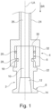
- FIG. 1 shows an unclaimed first embodiment of a medical coupling, in which a substantially cylindrical adapter 2 and a Coupling sleeve 4 are connected to each other.
- the adapter 2 has a male coupling section or first coupling section 6 on its end facing the coupling sleeve 4 and a first fastening section 8 on the other end facing away from the coupling sleeve 4.
- the adapter 2 has a continuous first channel 10, which extends in the direction widens conically away from the coupling sleeve 4.
- a first female Luer lock inner taper 12 is formed.
- first externally threaded section or first threaded section 14 is formed on the end of the first fastening section 8 facing away from the coupling sleeve 4 .
- the adapter 2 is attached to a (in 1 not shown) medical device or device 16, such as a dialyzer or a machine for extracorporeal blood treatment, attachable.
- a dialyzer the blood-carrying lines are connected, and in the case of a machine for extracorporeal blood treatment, the pressure lines that lead from the blood-carrying lines are connected, which direct a column of air to the pressure sensors.
- the adapter 2 can be fastened to any complementary Luer lock connector with a male outer cone.
- the first coupling section 6 also has a circumferential groove 18 .
- an O-ring 20 is arranged as a sealing element between the groove 18 and the end of the first coupling section 6 facing the coupling sleeve 4 .
- the O-ring 20 can rest on the outer circumference of the first coupling section 6, in an additional, in 3 be included in the sealing groove shown or be formed as a sealing element in one piece, for example by a 2K injection molding process, with the first coupling section 6 .
- a shoulder 22 is formed on the end of the first coupling section 6 facing away from the coupling sleeve 4 or between the first coupling section 6 and the first fastening section 8, which shoulder extends outwards in the radial direction.
- the coupling sleeve 4 functions as a female coupling section and is designed in one piece with a fluid line or hose 24 which is connected to the end of the coupling sleeve 4 remote from the adapter 2 .
- a second channel 26 is formed inside the Hose 24 and the coupling sleeve 4.
- a plurality of snap hooks 28 distributed uniformly in the circumferential direction are formed on the inner surface of the coupling sleeve 4 .
- the coupling sleeve 4 is now pushed onto the adapter 2 in the direction of a sliding direction SR, i.e. along a longitudinal axis LA of the adapter 2 and the coupling sleeve 4 in the direction of the adapter 2, then the snap hooks 28 come into contact with an end surface 30 facing the coupling sleeve 4 of the adapter 2.
- the coupling sleeve 4 made of plastic expands in the radial direction and the coupling sleeve 4 can be pushed further onto the adapter 2 or the first coupling section 6 in the sliding direction SR.
- the snap hooks 28 are level with the groove 18 in the axial direction, i.e.
- the coupling sleeve 4 returns to its original position, not expanded in the radial direction.
- the O-ring 20 of the adapter 2 comes to rest on a sealing surface 32 on the inside of the coupling sleeve 4 .
- a tight flow path is formed between the first channel 10 of the adapter 2 and the second channel 26 of the coupling sleeve 4 or of the hose 24 .
- the shoulder 22 limits the movement of the coupling sleeve 4 in the sliding direction SR, so that the snap hooks 28 remain in the groove 18 and the coupling sleeve 4 is thus securely connected to the adapter 2 .
- a certain amount of axial play between the adapter 2 and the coupling sleeve 4 is permitted as long as the snap hooks 28 are not moved out of the groove 18 and the O-ring 20 remains on the sealing surface 32.
- Figure 12 shows a second embodiment of a medical coupling, not claimed. Components that are the same as those in the first embodiment are provided with the same reference symbols.
- the adapter 2 ′ is designed in one piece with the medical device 16 .
- the adapter 2' is rather an extension of the medical device 16, at the end of which facing the coupling sleeve 4' the first coupling section 6 is designed as a male coupling section.
- the coupling sleeve 4' acts as a connector and thus connects the hose 24' to the medical device 16.
- the coupling sleeve 4' contains a female coupling section or second coupling section 34 on its end facing the medical device 16 and on its the hose 24 'end facing a second attachment portion 36.
- the connection of adapter 2' and coupling sleeve 4 'or first coupling portion 6 and second coupling portion 34 is analogous to the first embodiment.
- a continuous third channel 38 is also formed in the coupling sleeve 4' along the longitudinal axis LA.
- the second fastening section 36 is designed as a Luer lock connection. That is, the third channel 38 is surrounded by a male Luer lock male cone 40 extending toward the tubing 24'.
- an internally threaded section or second threaded section 42 is provided at the radially outer end of the second fastening section 36 .
- the end of the hose 24' facing the coupling sleeve 4' is designed as a Luer lock connection designed to complement the Luer lock connection of the coupling sleeve 4'.
- the second channel 26' widens conically in the direction of the coupling sleeve 4'.
- a second female luer lock inner taper 44 is formed.
- a second externally threaded section or third threaded section 46 is formed at the opposite end of the hose 24'.
- the adapter 2 can be fastened to the medical device via a Luer lock connection on the one hand and connected to the coupling sleeve 4′, which is fastened to the hose 24′ via a Luer lock connection, on the other hand in a latchable manner.
- FIG. 3 shows a third embodiment of a medical coupling according to the invention.
- the same components as those of the first and second embodiment are provided with the same reference symbols.
- the coupling sleeve 4" additionally has an unlocking device 48, which consists of a lever 50 and a pin 52.
- the lever 50 is arranged parallel to the longitudinal axis LA and the pin 52 perpendicular to the longitudinal axis LA.
- the end of the lever 50 facing the adapter 2" is articulated to an end of the pin 52 facing away from the adapter 2".
- the unlocking device 48 is provided in a recess 54 of the coupling sleeve 4" and is connected in an articulated manner to the coupling sleeve 4" via an articulation point 56.
- the coupling is thus designed to be detachable in the axial direction. However, it is also possible to do this using an unlocking button or the like instead of an unlocking lever.
- the unlocking device 48 is arranged on the coupling sleeve 4". However, it is also possible to arrange the unlocking device 48 on the adapter 2".
- the O-ring 20 is accommodated in a seal groove 60 .
- This configuration can also be used in the first and second embodiment, since in this way the snap hooks 28 can advantageously slide better over the O-ring 20 when the coupling sleeve is pushed on.
- the end surface 30 of the adapter 2" is not directly in contact with the coupling sleeve 4". Rather, the second channel 26 closes in the direction of the adapter 2'' towards a radially outwardly widened receiving opening 62, in which the first coupling section 6" can be accommodated.
- the first channel 10" is also widened outwards in the radial direction in the direction of the coupling sleeve 4".
- the adapter 2′′ of the third embodiment can either be fastenable to the medical device 16 analogously to the adapter 2 of the first embodiment or be designed in one piece with the medical device 16 analogously to the adapter 2′ of the second embodiment.
Landscapes
- Health & Medical Sciences (AREA)
- Heart & Thoracic Surgery (AREA)
- Animal Behavior & Ethology (AREA)
- General Health & Medical Sciences (AREA)
- Anesthesiology (AREA)
- Biomedical Technology (AREA)
- Hematology (AREA)
- Life Sciences & Earth Sciences (AREA)
- Veterinary Medicine (AREA)
- Engineering & Computer Science (AREA)
- Public Health (AREA)
- Pulmonology (AREA)
- External Artificial Organs (AREA)
- Infusion, Injection, And Reservoir Apparatuses (AREA)
- Vascular Medicine (AREA)
- Cardiology (AREA)
Description
- Die vorliegende Erfindung betrifft eine medizinische Kupplung zum fluiddichten Verbinden zweier fluidführender Abschnitte bei medizinischen Anwendungen, welche vorzugsweise den Anschluss eines extrakorporalen Blutschlauchsystems an einen Dialysator sowie an eine Maschine zur extrakorporalen Blutbehandlung ermöglichen, sowie ein medizinisches System mit einer medizinischen Kupplung.
- Bei der extrakorporalen Blutbehandlung oder auch Nierenersatztherapie wird das dem Patienten entnommene Blut außerhalb des Körpers in einem Kreislauf kontinuierlich durch einen Dialysator geleitet und dem Patienten wieder zugeführt. Dafür muss das extrakorporale Blutschlauchsystem, welches das Blut des Patienten führt, mit dem Dialysator verbunden werden. Diese Verbindung wird häufig über einen Luer-Lock-Anschluss realisiert.
- Beispielsweise ist aus der
DE 60 2004 003 477 T2 ein medizinischer Konnektor zum Verbinden eines Schlauches mit einer medizinischen Vorrichtung bekannt. Dieser Konnektor weist an seinem einen Ende einen Luer-Lock-Anschluss auf, über welchen er mit der medizinischen Vorrichtung verbunden werden kann. An seinem anderen Ende ist der Konnektor fest mit dem Schlauch verbunden bzw. ist der Schlauch in dem Konnektor eingeklebt. -
US 2010/0036329 A1 zeigt ein Hämostaseventil zum flüssigkeitsdichten Verbinden eines männlichen Abschnitts und eines weiblichen Abschnitts mittels eines verrastbaren Schnapprings. -
GB 2 091 364 A -
EP 2 138 202 A1 zeigt einen Luer-Lock-Anschluss mit einem männlichen Kopplungsabschnitt und einen weiblichen Kopplungsabschnitt, die durch eine umlaufende radiale Dichtung fluiddicht gekoppelt werden können. -
US 2009/0188575 A1 offenbart eine lösbare Schnellkupplung bei der zwei Vorsprünge am männlichen Kupplungsabschnitt mit jeweils einer Rückhalteöffnung in der Hülse axial verrasten. -
EP 1 731 128 A1 zeigt eine Schnellkupplung für Spritzen, die einen Fluidkanal der Kupplung je nach Kupplungsposition verschließt oder freigibt. Dazu sind am männlichen Kupplungsabschnitt zwei Einrastpositionen in Form von Vertiefungen vorgesehen, in die eine Rastvorrichtung der Hülse greift und den männlichen Kupplungsabschnitt in axialer Richtung festhält. -
WO 2006/039501 A2 zeigt einen als Schnellanschluss ausgeführten Hydrocephalus-Shunt, bei dem eine Hülse mit Rasthaken ausgebildete Arme aufweist, die hinter einen Vorsprung am männlichen Kupplungsabschnitt greifen können. -
US 2005/0101939 A1 zeigt eine Schnellkupplung mit einem lösbaren Verriegelungsmechanismus in Form eines verschiebbaren Blechs, der durch Anordnung zweier Federelemente in Kombination mit einem Keil die Kupplung von Hülse und männlichem Kupplungsabschnitt axial sichert bzw. freigibt. - Bei Systemen, bei denen Blutschläuche über eine Luer-Lock-Verbindung an eine medizinische Vorrichtung wie etwa einem Dialysator angeschlossen sind, kann es zu folgenden Problemen kommen. So kommt es häufig zu einem Verdrehen des Blutschlauches und oft folgt eine nicht erkannte Selbstlösung der Schraubverbindung. Dieser Nachteil ist, durch die nicht feste Verbindung des Luer-Lock-Anschlusses des Dialysators mit dem Schlauch, technisch bedingt. Es kann durch die Wärmeausdehnung der Luer-Lock-Anschlüsse zu einem Nachlassen der Reibung bzw. Selbsthemmung des Gewindes kommen. Durch die feste Verbindung des Schlauches am Luer-Lock-Anschluss kann der Schlauch ein permanentes Losdrehmoment auf das Gewinde ausüben. Des Weiteren ist die Güte der Schraubverbindung abhängig vom Bediener. Im Laufe der Therapie muss daher, durch das Bedienpersonal, die Verbindung auf korrekten Sitz geprüft und ggf. korrigiert werden.
- Es ist daher die Aufgabe der vorliegenden Erfindung eine Kupplung bereitzustellen, bei der sichergestellt wird, dass sich Schläuche bzw. Blutschläuche nicht verdrehen und die eine vom Anwender drehmomentunabhängige Verbindung schafft, sowie das zeitaufwendige Prüfen und Korrigieren der Verbindung vermeidet.
- Diese Aufgabe wird erfindungsgemäß durch eine medizinische Kupplung mit den Merkmalen des Anspruchs 1 sowie durch ein medizinisches System mit den Merkmalen des Anspruchs 6 gelöst. Vorteilhafte Weiterbildungen der Erfindung sind in den Unteransprüchen angegeben.
- Die erfindungsgemäße medizinische (Fluid-) Kupplung zum fluiddichten Verbinden (mindestens) zweier fluidführender Abschnitte bei medizinischen Anwendungen ist als axial verrastbare Schnellkupplung ausgebildet und weist einen männlichen Kupplungsabschnitt mit einem durchgängigen ersten Kanal und einen über den männlichen Kupplungsabschnitt schiebbaren weiblichen Kupplungsabschnitt mit einem durchgängigen zweiten Kanal auf. Zudem ist am Außenumfang des männlichen Kupplungsabschnitts und/oder am Innenumfang des weiblichen Kupplungsabschnitts eine vorzugsweise umlaufende Radialdichtung vorgesehen.
- Mit der erfindungsgemäßen medizinischen Kupplung ist es somit beispielsweise möglich, eine Fluidleitung und ein medizinisches Gerät, oder auch zwei Fluidleitungen, als Beispiele fluidführender Abschnitte, einfach miteinander zu verbinden. Die Kupplung wird über das Verbinden eines männlichen Kupplungsabschnitts und eines weiblichen Kupplungsabschnitts erzielt. Dabei ist der männliche Kupplungsabschnitt als eine Art zylindrischer Vorsprung mit einem durchgängigen, innenliegenden Kanal ausgebildet. Der weibliche Kupplungsabschnitt ist als eine Art Hülse ausgebildet, in welcher der männliche Kupplungsabschnitt teilweise oder vollständig aufgenommen werden kann. Zum Verbinden wird der weibliche Kupplungsabschnitt in axialer Richtung der Hülse bzw. des zylindrischen Vorsprungs über den männlichen Kupplungsabschnitt geschoben. Dabei verrasten die beiden Kupplungsabschnitte (unlösbar) miteinander. Bei einem Einsatz in der Nierenersatztherapie werden beispielsweise das extrakorporale Blutschlauchsystem und der Dialysator nach der Therapie nicht mehr getrennt. Eine unlösbare Verbindung ist daher nicht nachteilhaft. Zudem stellt die zwischen dem männlichen und dem weiblichen Kupplungsabschnitt ausgebildete Radialdichtung sicher, dass die beiden Kupplungsabschnitte und somit die beiden fluidführenden Abschnitte dichtend miteinander verbunden sind.
- Mit der so ausgeführten Kupplung kann schnell und einfach eine Verbindung zweier fluidführender Abschnitte erzielt werden. Es sind dafür keine zusätzlichen Sicherungselemente notwendig. Außerdem wird auf ein zeitaufwändiges Verschrauben oder Verdrehen der beiden Kupplungsabschnitte zueinander verzichtet. Die Verbindung ist somit auch sicherer, da sich die beiden Kupplungsabschnitte nicht selbständig voneinander lösen oder losdrehen können. Zudem ist aufgrund der Radialdichtung eine relative Drehung um die Längsachse der Kupplung des weiblichen Kupplungsabschnitts bezüglich des männlichen Kupplungsabschnitts möglich.
- Gemäß einem Aspekt der Erfindung kann der männliche Kupplungsabschnitt einstückig mit einem medizinischen Gerät oder einer medizinischen Vorrichtung, insbesondere einem Dialysator oder einer Maschine zur extrakorporalen Blutbehandlung, ausgebildet sein.
- Dadurch sind keine zusätzlichen Bauteile für den Anschluss an das medizinische Gerät notwendig und es ist somit eine einfache, bauteilarme und kostengünstige Konfiguration möglich.
- Gemäß einem Aspekt der Erfindung kann der männliche Kupplungsabschnitt einen ersten Befestigungsabschnitt aufweisen.
- Gemäß einem Aspekt der Erfindung kann der männliche Kupplungsabschnitt über den ersten Befestigungsabschnitt an einem medizinischen Gerät befestigbar sein.
- Gemäß einem Aspekt der Erfindung kann der erste Befestigungsabschnitt des männlichen Kupplungsabschnitts als ein Luer-Lock-Anschluss ausgebildet sein, welcher mit einem Luer-Lock-Anschluss des medizinischen Geräts verbindbar ist.
- Gemäß einem Aspekt der Erfindung kann der erste Befestigungsabschnitt des männlichen Kupplungsabschnitts als ein Luer-Lock-Anschluss mit einem weiblichen Innenkegel ausgebildet sein, welcher mit einem Luer-Lock-Anschluss mit einem männlichen Außenkegel des medizinischen Geräts verbindbar ist.
- Dadurch, dass der männliche Kupplungsabschnitt über den ersten Befestigungsabschnitt mit dem medizinischen Gerät verbunden wird, ist es möglich, die erfindungsgemäße Kupplung auch für bereits vorhandene medizinische Geräte zu verwenden. Mit anderen Worten kann der männliche Kupplungsabschnitt als eine Art Adapter auf beispielsweise einen Luer-Lock-Anschluss des medizinischen Gerätes geschraubt werden und der männliche Kupplungsabschnitt verbindet somit das medizinische Gerät mit dem weiblichen Kupplungsabschnitt.
- Gemäß einem Aspekt der Erfindung kann der erste Befestigungsabschnitt des männlichen Kupplungsabschnitts als ein Innengewindeabschnitt ausgebildet sein, welcher mit einem Außengewindeabschnitt des medizinischen Geräts verbindbar ist.
- Somit kann beispielsweise der männliche Kupplungsabschnitt als ein Teil des Deckels des medizinischen Geräts ausgebildet sein, welcher mittels eines Gewindes auf ein Gehäuse des medizinischen Geräts geschraubt werden kann.
- Gemäß einem Aspekt der Erfindung kann der weibliche Kupplungsabschnitt einstückig mit einer Fluidleitung ausgebildet sein.
- Dadurch sind keine zusätzlichen Bauteile für den Anschluss an die Fluidleitung notwendig und es ist somit eine einfache, bauteilarme und kostengünstige Konfiguration möglich.
- Gemäß einem Aspekt der Erfindung kann der weibliche Kupplungsabschnitt einen zweiten Befestigungsabschnitt aufweisen.
- Gemäß einem Aspekt der Erfindung kann der weibliche Kupplungsabschnitt über den zweiten Befestigungsabschnitt an einer Fluidleitung befestigbar sein.
- Gemäß einem Aspekt der Erfindung kann der zweite Befestigungsabschnitt des weiblichen Kupplungsabschnitts als ein Luer-Lock-Anschluss ausgebildet sein, welcher mit einem Luer-Lock-Anschluss der Fluidleitung verbindbar ist.
- Gemäß einem Aspekt der Erfindung kann der zweite Befestigungsabschnitt des weiblichen Kupplungsabschnitts als ein Luer-Lock-Anschluss mit einem männlichen Außenkegel ausgebildet sein, welcher mit einem Luer-Lock-Anschluss mit einem weiblichen Innenkegel der Fluidleitung verbindbar ist.
- Dadurch, dass der weibliche Kupplungsabschnitt über den zweiten Befestigungsabschnitt mit der Fluidleitung verbunden wird, ist es möglich, die erfindungsgemäße Kupplung auch für bereits vorhandene Fluidleitungen zu verwenden. Mit anderen Worten kann der weibliche Kupplungsabschnitt als eine Art Konnektor auf beispielsweise einen Luer-Lock-Anschluss der Fluidleitung geschraubt werden und der weibliche Kupplungsabschnitt verbindet somit die Fluidleitung mit dem männlichen Kupplungsabschnitt.
- Gemäß der Erfindung weist der männliche Kupplungsabschnitt eine vorzugsweise umlaufende Nut auf, in die ein Teil des weiblichen Kupplungsabschnitts einrastet.
- Gemäß der Erfindung sind der männliche Kupplungsabschnitt und der weibliche Kupplungsabschnitt über eine Verriegelungsvorrichtung miteinander verbindbar.
- Gemäß der Erfindung ist die Verriegelungsvorrichtung an dem weiblichen Kupplungsabschnitt vorgesehen.
- Die Verriegelungsvorrichtung ist so ausgebildet, dass ein über einen Hebel betätigbarer Stift in eine Nut geführt werden kann. Die Verriegelungsvorrichtung ist somit eine sichere Verbindung ohne beispielsweise das Material des weiblichen Kupplungsabschnitts übermäßig zu beanspruchen oder das Dichtungselement zu beschädigen.
- Gemäß der Erfindung weist der männliche Kupplungsabschnitt einen Anschlag bzw. eine Schulter auf, welche die Bewegung des weiblichen Kupplungsabschnittes in axialer Richtung begrenzt.
- Gemäß der Erfindung können der männliche Kupplungsabschnitt und der weibliche Kupplungsabschnitt durch eine Entriegelungsvorrichtung voneinander gelöst werden.
- Gemäß der Erfindung ist die Entriegelungsvorrichtung an dem weiblichen Kupplungsabschnitt vorgesehen.
- Gemäß einem Aspekt der Erfindung sind die Verriegelungsvorrichtung und die Entriegelungsvorrichtung gleichartig ausgebildet.
- Es ist somit möglich, durch einen Entriegelungstaster oder -hebel die durch Einrasten miteinander verbundenen männlichen und weiblichen Kupplungsabschnitte wieder zerstörungsfrei voneinander zu lösen. Alternativ kann das Verbinden und Lösen auch über die Ver- bzw. Entriegelungsvorrichtung realisiert werden.
- Das erfindungsgemäße medizinische System enthält eine erste Fluidleitung und ein medizinisches Gerät und/oder einer zweiten Fluidleitung. In der ersten Fluidleitung ist ein erster Kanal und in dem medizinischen Gerät und/oder der zweiten Fluidleitung ist ein zweiter Kanal vorgesehen. Die erste Fluidleitung und das medizinische Gerät und/oder die zweite Fluidleitung können über eine erfindungsgemäße medizinische Kupplung miteinander verbunden werden, sodass der erste Kanal und der zweite Kanal dichtend miteinander verbunden sind.
- In dem medizinischen System dient die medizinische Kupplung dazu, mindestens zwei fluidführende Abschnitte miteinander zu verbinden bzw. eine Verbindung herzustellen, sodass ein Fluid von einer Leitung in ein medizinisches Gerät oder eine weitere Leitung strömen bzw. fließen kann oder umgekehrt. Die medizinische Kupplung kann dabei einen oder mehrere der vorstehend beschriebenen Aspekte bzw. Vorteile enthalten.
- Zusammenfassend kann mit der erfindungsgemäßen medizinischen Kupplung und dem erfindungsgemäßen medizinischen System, besonders beim Einsatz in der Nierenersatztherapie, die Benutzerfreundlichkeit verbessert werden und es können Rüstzeiten verkürzt werden. Zudem wird ein Verdrehen der Blutschläuche verhindert und eine drehmomentunabhängige Verbindung wird realisiert, welche sich während der Therapie nicht selbstständig lösen kann. Dadurch entfällt das zeitaufwendige Prüfen und Korrigieren der Verbindung durch den Bediener, es kommt zu keinem unbemerkten Blutverlust, was zu einem Patientenrisiko führen könnte, und eine Fehlmessung der Drücke während der Therapie kann verhindert werden.
-
-
Fig. 1 zeigt eine Schnittansicht eines Adapters mit daran gekoppelter Kupplungshülse gemäß einer nicht beanspruchten ersten Ausführungsform. -
Fig. 2 zeigt eine Schnittansicht eines medizinischen Geräts mit daran gekoppelter Kupplungshülse gemäß einer nicht beanspruchten zweiten Ausführungsform. -
Fig. 3 zeigt eine Schnittansicht eines Adapters mit daran gekoppelter Kupplungshülse, welche eine Entriegelungsvorrichtung enthält, gemäß einer erfindungsgemäßen dritten Ausführungsform. -
Fig. 1 zeigt eine nicht beanspruchte erste Ausführungsform einer medizinischen Kupplung, bei der ein im Wesentlichen zylindrischer Adapter 2 und eine Kupplungshülse 4 miteinander verbunden sind. Der Adapter 2 hat an seinem der Kupplungshülse 4 zugewandten Ende einen männlichen Kupplungsabschnitt bzw. ersten Kupplungsabschnitt 6 und an dem anderen, der Kupplungshülse 4 abgewandten Ende einen ersten Befestigungsabschnitt 8. Zudem weist der Adapter 2 einen durchgängigen ersten Kanal 10 auf, welcher sich in Richtung weg von der Kupplungshülse 4 kegelförmig aufweitet. Mit anderen Worten wird ein erster weiblicher Luer-Lock-Innenkegel 12 ausgebildet. Weiterhin ist an dem der Kupplungshülse 4 abgewandten Ende des ersten Befestigungsabschnitts 8 ein erster Außengewindeabschnitt bzw. erster Gewindeabschnitt 14 ausgebildet. Über den ersten weiblichen Luer-Lock-Innenkegel 12 und den ersten Gewindeabschnitt 14 ist der Adapter 2 an einem (inFig. 1 nicht dargestellten) medizinischen Gerät bzw. Vorrichtung 16, wie etwa einem Dialysator oder einer Maschine zur extrakorporalen Blutbehandlung, befestigbar. Im Falle eines Dialysators werden die blutführenden Leitungen angeschlossen und im Falle einer Maschine zur extrakorporalen Blutbehandlung werden die von den blutführenden Leitungen abgehenden Druckleitungen angeschlossen, die eine Luftsäule an die Druckaufnehmer leiten. Mit anderen Worten ist der Adapter 2 an jedem komplementär ausgebildeten Luer-Lock-Anschluss mit männlichem Außenkegel befestigbar. - Der erste Kupplungsabschnitt 6 weist ferner eine umlaufende Nut 18 auf. Zudem ist zwischen der Nut 18 und dem der Kupplungshülse 4 zugewandten Ende des ersten Kupplungsabschnitts 6 ein O-Ring 20 als Dichtungselement angeordnet. Der O-Ring 20 kann dabei am Außenumfang des ersten Kupplungsabschnitts 6 anliegen, in einer zusätzlichen, in
Fig. 3 dargestellten Dichtungsnut aufgenommen sein oder als Dichtungselement einstückig, z.B. durch einen 2K-Spritzgussprozess, mit dem ersten Kupplungsabschnitt 6 ausgebildet sein. Zusätzlich ist an dem der Kupplungshülse 4 abgewandten Ende des ersten Kupplungsabschnitts 6 bzw. zwischen dem ersten Kupplungsabschnitt 6 und dem ersten Befestigungsabschnitt 8 eine Schulter 22 ausgebildet, welche sich in radialer Richtung nach Außen erstreckt. - Die Kupplungshülse 4 fungiert als weiblicher Kupplungsabschnitt und ist einstückig mit einer Fluidleitung bzw. einem Schlauch 24 ausgebildet, welcher sich an dem von dem Adapter 2 entfernten Ende der Kupplungshülse 4 anschließt. Im Inneren des Schlauches 24 und der Kupplungshülse 4 ist ein zweiter Kanal 26 ausgebildet. Weiterhin sind auf der Innenfläche der Kupplungshülse 4 mehrere, gleichmäßig in der Umfangsrichtung verteilte Schnapphaken 28 ausgebildet. Es ist jedoch auch möglich, dass nur ein einziger umlaufender Schnapphaken ausgebildet ist.
- Wird nun die Kupplungshülse 4 in Richtung einer Schieberichtung SR, d.h. entlang einer Längsachse LA des Adapters 2 und der Kupplungshülse 4 in Richtung auf den Adapter 2 zu, auf den Adapter 2 geschoben, dann stoßen die Schnapphaken 28 auf eine der Kupplungshülse 4 zugewandte Endfläche 30 des Adapters 2. Dies führt dazu, dass sich die aus Kunststoff ausgebildete Kupplungshülse 4 in radialer Richtung aufweitet und die Kupplungshülse 4 weiter in der Schieberichtung SR auf den Adapter 2 bzw. den ersten Kupplungsabschnitt 6 geschoben werden kann. Sobald die Schnapphaken 28 in axialer Richtung, d.h. entlang der Längsachse LA, auf Höhe der Nut 18 sind, rasten diese in die Nut 18 ein und die Kupplungshülse 4 kehrt in ihre ursprüngliche, nicht in radialer Richtung aufgeweitete Position zurück. Dabei kommt der O-Ring 20 des Adapters 2 auf einer Dichtungsfläche 32 auf der Innenseite der Kupplungshülse 4 zum Anliegen. Dadurch wird ein dichter Strömungspfad zwischen dem ersten Kanal 10 des Adapters 2 und dem zweiten Kanal 26 der Kupplungshülse 4 bzw. des Schlauchs 24 ausgebildet. Weiterhin begrenzt die Schulter 22 die Bewegung der Kupplungshülse 4 in der Schieberichtung SR, sodass die Schnapphaken 28 in der Nut 18 verbleiben und somit die Kupplungshülse 4 sicher mit dem Adapter 2 verbunden ist. Jedoch ist ein gewisses axiales Spiel zwischen dem Adapter 2 und der Kupplungshülse 4 erlaubt, solange die Schnapphaken 28 nicht aus der Nut 18 herausbewegt werden und der O-Ring 20 auf der Dichtungsfläche 32 verbleibt.
- Mit der Kupplung bzw. Schnellkupplung kann nicht nur schnell eine dichte und kraftunabhängige Verbindung zweier fluidführender Abschnitte wie der Kupplungshülse 4 mit Schlauch 24 und dem Adapter 2 hergestellt werden, sondern es ist aufgrund der Radialdichtung mittels O-Ring 20 auch möglich, dass sich die Kupplungshülse 4 und der Adapter 2 relativ zueinander um die Längsachse LA drehen können. Dadurch wird ein Verdrehen des Schlauchs 24 oder auch ein Lösen der Luer-Lock-Verbindung zwischen dem Adapter 2 und dem medizinischen Gerät 16 verhindert. Dabei ist es auch möglich, dass das Dichtungselement in der Kupplungshülse 4 vorgesehen ist und nach dem Verbinden mit einer Dichtungsfläche des Adapters 2 in Kontakt kommt.
-
Fig. 2 zeigt eine nicht beanspruchte zweite Ausführungsform einer medizinischen Kupplung. Gleiche Bauteile wie die der ersten Ausführungsform sind dabei mit denselben Bezugszeichen versehen. - In der zweiten Ausführungsform ist der Adapter 2' einstückig mit dem medizinischen Gerät 16 ausgebildet. Mit anderen Worten ist der Adapter 2' vielmehr ein Fortsatz des medizinischen Geräts 16, an dessen der Kupplungshülse 4' zugewandten Ende der erste Kupplungsabschnitt 6 als männlicher Kupplungsabschnitt ausgebildet ist.
- In der zweiten Ausführungsform fungiert die Kupplungshülse 4' als Konnektor und verbindet so den Schlauch 24' mit dem medizinischen Gerät 16. Die Kupplungshülse 4' enthält an ihrem, dem medizinischen Gerät 16 zugewandten Ende einen weiblichen Kupplungsabschnitt bzw. zweiten Kupplungsabschnitt 34 und an ihrem, dem Schlauch 24' zugewandten Ende einen zweiten Befestigungsabschnitt 36. Die Verbindung von Adapter 2' und Kupplungshülse 4' bzw. erstem Kupplungsabschnitt 6 und zweiten Kupplungsabschnitt 34 erfolgt analog der ersten Ausführungsform.
- In der Kupplungshülse 4' ist außerdem entlang der Längsachse LA ein durchgängiger dritter Kanal 38 ausgebildet. Der zweite Befestigungsabschnitt 36 ist als Luer-Lock-Anschluss ausgebildet. D.h., der dritte Kanal 38 wird von einem sich in Richtung des Schlauchs 24' erstreckenden männlichen Luer-Lock-Außenkegel 40 umschlossen. Zudem ist am radial äußeren Ende des zweiten Befestigungsabschnitts 36 ein Innengewindeabschnitt bzw. zweiter Gewindeabschnitt 42 vorgesehen.
- Das der Kupplungshülse 4' zugewandte Ende des Schlauchs 24' ist als ein komplementär zum Luer-Lock-Anschluss der Kupplungshülse 4' ausgebildeter Luer-Lock-Anschluss ausgebildet. So weitet sich der zweite Kanal 26' in Richtung zu der Kupplungshülse 4' hin kegelförmig auf. Mit anderen Worten wird ein zweiter weiblicher Luer-Lock-Innenkegel 44 ausgebildet. Weiterhin ist an dem der Kupplungshülse 4' abgewandtem Ende des Schlauchs 24' ein zweiter Außengewindeabschnitt bzw. dritter Gewindeabschnitt 46 ausgebildet.
- Werden nun der erste Kupplungsabschnitt 6 und die Kupplungshülse 4' wie vorstehend beschrieben gekoppelt und werden zusätzlich der Schlauch 24' und die Kupplungshülse 4' über die Luer-Lock-Verbindung miteinander verbunden, kann ein dichter Strömungspfad von dem zweiten Kanal 26' im Schlauch 24' über den dritten Kanal 38 in der Kupplungshülse 4' zu dem ersten Kanal 10' im medizinischen Gerät 16 hergestellt werden.
- In den vorstehend beschriebenen Ausführungsformen werden verschiedene Möglichkeiten gezeigt, wie der Schlauch 24 und das medizinische Gerät 16 miteinander verbunden werden können. Es sind jedoch auch weitere Kombinationsmöglichkeiten der verschiedenen Verbindungen möglich. So kann beispielsweise der Adapter 2 einerseits über eine Luer-Lock-Verbindung an dem medizinischen Gerät befestigt und andererseits mit der Kupplungshülse 4', welche über eine Luer-Lock-Verbindung an dem Schlauch 24' befestigt ist, verrastbar verbunden sein.
-
Fig. 3 zeigt eine erfindungsgemäße dritte Ausführungsform einer medizinischen Kupplung. Gleiche Bauteile wie die der ersten und zweiten Ausführungsform sind dabei mit denselben Bezugszeichen versehen. - In der dritten Ausführungsform weist die Kupplungshülse 4" zusätzlich eine Entriegelungsvorrichtung 48 auf, welche aus einem Hebel 50 und einem Stift 52 besteht. In dem in
Fig. 3 gezeigten verriegelten Zustand ist der Hebel 50 parallel zu der Längsachse LA und der Stift 52 senkrecht zur Längsachse LA angeordnet. Dabei ist der Hebel 50 seinem dem Adapter 2" zugewandeten Ende mit einem dem Adapter 2" abgewandeten Ende des Stiftes 52 gelenkig verbunden. Ferner ist die Entriegelungsvorrichtung 48 in einer Aussparung 54 der Kupplungshülse 4" vorgesehen und über eine Anlenkstelle 56 gelenkig mit der Kupplungshülse 4" verbunden. - Um die Kupplungshülse 4" mit dem Adapter 2" verbinden zu können, muss der Hebel 50 an seinem dem Adapter 2" abgewanden Ende in radialer Richtung nach Innen bewegt werden. Dadurch wird der Stift 52 in radialer Richtung nach Außen bewegt und die Kupplungshülse 4" kann in der Schieberichtung SR auf den Adapter 2" bzw. den ersten Kupplungsabschnitt 6" geschoben werden. Sobald eine dem Adapter 2" zugewandte vordere Begrenzungsfläche 58 der Kupplungshülse 4" gegen die Schulter 22 stößt, befinden sich die Nut 18 und der Stift 52 in axialer Richtung auf gleicher Höhe. Wenn nun der Hebel 50 losgelassen d.h. nicht mehr betätigt wird, kehrt der Hebel in seine Ausgangsposition parallel zur Längsachse LA zurück und der Stift 52 schiebt sich in die Nut 18, sodass der Adapter 2" und die Kupplungshülse 4" miteinander verbunden sind. Um die Verbindung zu lösen, muss wiederum der Hebel 50 betätigt, d.h. in radialer Richtung nach Innen bewegt werden. Dadurch bewegt sich der Stift 52 aus der Nut 18 heraus und die Kupplungshülse 4" kann entgegen der Schieberichtung SR von dem Adapter 2" abgezogen werden.
- Die Kupplung ist somit in axialer Richtung lösbar ausgeführt. Es ist jedoch auch möglich, dies anstelle über einen Entriegelungshebel über einen Entriegelungstaster oder dergleichen zu realisieren. In der vorstehend beschriebenen dritten Ausführungsform ist die Entriegelungsvorrichtung 48 an der Kupplungshülse 4" angeordnet. Es ist jedoch auch möglich, die Entriegelungsvorrichtung 48 an dem Adapter 2"anzuordnen.
- Nachfolgend werden einige Unterschiede bzw. vorteilhafte Ausgestaltungen der dritten Ausführungsform gegenüber der ersten und zweiten Ausführungsform beschrieben.
- In der dritten Ausführungsform ist der O-Ring 20 in einer Dichtungsnut 60 aufgenommen. Dadurch wird die radiale Ausdehnung des Dichtungselements begrenzt. Diese Konfiguration kann auch in der ersten und zweiten Ausführungsform verwendet werden, da so vorteilhafterweise die Schnapphaken 28 beim Aufschieben der Kupplungshülse besser über den O-Ring 20 gleiten können.
- Außerdem liegt in der dritten Ausführungsform die Endfläche 30 des Adapters 2" nicht direkt an der Kupplungshülse 4". Vielmehr schließt sich dem zweiten Kanal 26 in Richtung zu dem Adapter 2" hin eine radial nach Außen aufgeweitete Aufnahmeöffnung 62 an, in welcher der erste Kupplungsabschnitt 6" aufgenommen werden an. Auch der erste Kanal 10" ist in Richtung zu der Kupplungshülse 4" hin in radialer Richtung nach Außen hin aufgeweitet.
- Weiterhin muss in der dritten Ausführungsform nicht nur eine Verriegelung- bzw. Entriegelungsvorrichtung 48 vorgesehen sein. Es können auch zwei oder mehrere vorzugsweise gleichmäßig in der Umfangsrichtung verteilt sein. Zudem kann der Adapter 2" der dritten Ausführungsform entweder analog zu dem Adapter 2 der ersten Ausführungsform an dem medizinischen Gerät 16 befestigbar sein oder analog zu dem Adapter 2' der zweiten Ausführungsform einstückig mit dem medizinischen Gerät 16 ausgebildet sein.
Claims (6)
- Medizinische Kupplung zum flüssigkeitsdichten Verbinden zweier fluidführender Abschnitte (24') bei medizinischen Anwendungen, wobeidie Kupplung als axial Schnellkupplung ausgebildet ist und einen männlichen Kupplungsabschnitt (6"), der als zylindrischer Vorsprung mit einem durchgängigen, innenliegenden ersten Kanal (10") ausgebildet ist, und einen über den männlichen Kupplungsabschnitt (6") schiebbaren weiblichen Kupplungsabschnitt (4") mit einem durchgängigen zweiten Kanal (26) aufweist;der männliche Kupplungsabschnitt (6") und der weibliche Kupplungsabschnitt (4") miteinander verrastbar sind; undam Außenumfang des männlichen Kupplungsabschnitts (6") und/oder am Innenumfang des weiblichen Kupplungsabschnitts (4") eine Radialdichtung (20) vorgesehen ist,dadurch gekennzeichnet, dassder männliche Kupplungsabschnitt (6") eine Nut (18) aufweist, undder männliche Kupplungsabschnitt (6") an einem dem weiblichen Kupplungsabschnitt (4") abgewandten Ende einen Anschlag oder eine Schulter (22) aufweist, die sich in radialer Richtung nach Außen streckt und dazu vorgesehen ist, die Bewegung des weiblichen Kupplungsabschnitts (4") in axialer Richtung zu begrenzen,wobei der männliche Kupplungsabschnitt (6") und der weibliche Kupplungsabschnitt (4") durch eine Entriegelungsvorrichtung (48) miteinander verbindbar oder voneinander lösbar sind, wobei die Entriegelungsvorrichtung (48) in einem verriegelten Zustand einen Hebel (50) parallel zu einer Längsachse (LA) der medizinischen Kupplung und einen Stift (52) senkrecht zur Längsachse (LA) aufweist,wobei der Hebel (50) an seinem dem männlichen Kupplungsabschnitt (6") zugewandeten Ende gelenkig mit einem radial äußeren Ende des Stiftes (52) verbunden ist,wobei der Stift (52) durch eine gelenkige Bewegung des Hebels (50) über eine Anlenkstelle (56) betätigbar ist, um sich in die Nut (18) zu schieben oder sich aus der Nut (18) heraus zu bewegen, so dass der männliche Kupplungsabschnitt (6") und der weibliche Kupplungsabschnitt (4") miteinander verbindbar oder voneinander lösbar sind, undwobei die Entriegelungsvorrichtung (48) an dem weiblichen Kupplungsabschnitt (4") vorgesehen ist.
- Medizinische Kupplung gemäß Anspruch 1, wobei
der männliche Kupplungsabschnitt (6") einstückig mit einem medizinischen Gerät (16) ausgebildet ist. - Medizinische Kupplung gemäß Anspruch 1, wobeider männliche Kupplungsabschnitt (6") einen ersten Befestigungsabschnitt (8) aufweist, und wobeider männliche Kupplungsabschnitt (6") über den ersten Befestigungsabschnitt (8) an einem medizinischen Gerät (16) befestigbar ist.
- Medizinische Kupplung gemäß Anspruch 3, wobei
der erste Befestigungsabschnitt (8) des männlichen Kupplungsabschnitts (6") als ein Luer-Lock-Anschluss ausgebildet ist, welcher mit einem Luer-Lock-Anschluss des medizinischen Geräts (16) verbindbar ist. - Medizinische Kupplung gemäß einem der Ansprüche 1 bis 4, wobei
der weibliche Kupplungsabschnitt (4") einstückig mit einer Fluidleitung (24) ausgebildet ist. - Medizinisches System, mit:einer ersten Fluidleitung (24) undeinem medizinischen Gerät (16) und/oder einer zweiten Fluidleitung, wobeiin der ersten Fluidleitung (24) ein erster Kanal (26) und in dem medizinischen Gerät (16) und/oder der zweiten Fluidleitung ein zweiter Kanal (10") vorgesehen ist, und wobeidie erste Fluidleitung (24) und das medizinische Gerät (16) und/oder die zweite Fluidleitung über eine medizinische Kupplung gemäß einem der Ansprüche 1 bis 5 miteinander verbunden werden können, sodass der erste Kanal (26) und der zweite Kanal (10") dichtend miteinander verbunden sind.
Applications Claiming Priority (1)
| Application Number | Priority Date | Filing Date | Title |
|---|---|---|---|
| DE102016101911.9A DE102016101911A1 (de) | 2016-02-03 | 2016-02-03 | Medizinische Kupplung und medizinisches System mit einer medizinischen Kupplung |
Publications (2)
| Publication Number | Publication Date |
|---|---|
| EP3202455A1 EP3202455A1 (de) | 2017-08-09 |
| EP3202455B1 true EP3202455B1 (de) | 2023-04-26 |
Family
ID=57850917
Family Applications (1)
| Application Number | Title | Priority Date | Filing Date |
|---|---|---|---|
| EP17151781.6A Active EP3202455B1 (de) | 2016-02-03 | 2017-01-17 | Medizinische kupplung und medizinisches system mit einer medizinischen kupplung |
Country Status (5)
| Country | Link |
|---|---|
| US (1) | US10569074B2 (de) |
| EP (1) | EP3202455B1 (de) |
| JP (1) | JP6893791B2 (de) |
| CN (2) | CN208003259U (de) |
| DE (1) | DE102016101911A1 (de) |
Families Citing this family (18)
| Publication number | Priority date | Publication date | Assignee | Title |
|---|---|---|---|---|
| WO2013180304A1 (ja) * | 2012-06-01 | 2013-12-05 | 日本ノズル株式会社 | 不織布製造装置、及び不織布製造方法 |
| DE102016101911A1 (de) * | 2016-02-03 | 2017-08-03 | B. Braun Avitum Ag | Medizinische Kupplung und medizinisches System mit einer medizinischen Kupplung |
| WO2018097738A1 (en) * | 2016-11-23 | 2018-05-31 | Fisher And Paykel Healthcare Limited | High flow luer connector |
| DE102018102542A1 (de) | 2018-01-29 | 2019-08-01 | Woco Industrietechnik Gmbh | Vorrichtung zur Handhabung von Fluiden sowie Verfahren zur Herstellung derselben |
| US11077260B2 (en) | 2018-02-14 | 2021-08-03 | Becton, Dickinson And Company | Flow control plug securement |
| KR102849171B1 (ko) * | 2018-05-08 | 2025-08-27 | 보스턴 사이언티픽 메디칼 디바이스 리미티드 | 디바이스용 결합 메커니즘들 |
| US11383073B2 (en) * | 2018-06-15 | 2022-07-12 | Carefusion 303, Inc. | Luer having tubing retention pocket bond |
| CN109646749A (zh) * | 2019-01-04 | 2019-04-19 | 刘春迎 | 一种妇科护理阴道冲洗装置 |
| GB201907070D0 (en) | 2019-05-20 | 2019-07-03 | Metis Design Bv | Connector for a gastrostomy device |
| BR112021026099A2 (pt) * | 2019-07-09 | 2022-02-15 | Becton Dickinson Co | Conector neuraxial |
| DE102019123806A1 (de) * | 2019-09-05 | 2021-03-11 | Fresenius Medical Care Deutschland Gmbh | Medizinischer Konnektor mit automatischer Abdichtung bei der Dekonnektion |
| DE102020114117A1 (de) * | 2020-05-26 | 2021-12-02 | Bayerische Motoren Werke Aktiengesellschaft | Leitungskupplungsbaugruppe |
| DE102020133686A1 (de) | 2020-12-16 | 2022-06-23 | Fresenius Medical Care Deutschland Gmbh | Konnektor für Dialysatorport, Dialysator, Verfahren und Blutbehandlungsvorrichtung |
| EP4262643A1 (de) * | 2021-01-20 | 2023-10-25 | C. R. Bard, Inc. | Fluidleitungsverbinder auf einem pad für arktische gelpads |
| CN113357462B (zh) * | 2021-05-27 | 2022-11-01 | 宁波城市职业技术学院 | 一种快拆式的排水管 |
| DE102022211360A1 (de) * | 2022-10-26 | 2024-05-02 | Raumedic Ag | Medizinischer Fluid-Konnektor |
| USD1105422S1 (en) | 2024-02-09 | 2025-12-09 | Icu Medical, Inc. | Medical connector cover |
| CN118286585B (zh) * | 2024-03-25 | 2024-10-18 | 南京鼓楼医院 | 一种柔性膜枢驱动式血泵 |
Family Cites Families (23)
| Publication number | Priority date | Publication date | Assignee | Title |
|---|---|---|---|---|
| GB2091364B (en) * | 1981-01-20 | 1985-04-11 | Leygard Ltd | Fluid-tight seal |
| US5688254A (en) * | 1983-01-24 | 1997-11-18 | Icu Medical, Inc. | Medical connector |
| WO2004064895A2 (en) * | 2003-01-15 | 2004-08-05 | Pall Corporation | Luer connectors and fitting |
| CA2555464C (en) | 2003-02-12 | 2011-11-08 | Signe Thorning Mejlhede | A medical connector and a method of injection moulding such a connector |
| US20050020980A1 (en) * | 2003-06-09 | 2005-01-27 | Yoshio Inoue | Coupling system for an infusion pump |
| US7153296B2 (en) * | 2003-11-07 | 2006-12-26 | Mitchell Martin S | Releasable tubing connector |
| US7347853B2 (en) * | 2004-05-12 | 2008-03-25 | C. R. Bard, Inc. | Catheter with removable extension |
| WO2006039501A2 (en) * | 2004-09-30 | 2006-04-13 | Northeastern University | Hydrocephalus shunt system quick connector assembly |
| DE102004052475A1 (de) * | 2004-10-28 | 2006-05-04 | Eaton Fluid Power Gmbh | Zugfeste Steckkupplung |
| ITMO20050141A1 (it) * | 2005-06-09 | 2006-12-10 | Aries S R L | Dispositivo di chiusura per contenitori o linee di somministrazione di fluidi medicinali o fermaceutici. |
| US8852167B2 (en) * | 2005-12-01 | 2014-10-07 | Bayer Medical Care Inc. | Medical connector |
| US20090188575A1 (en) * | 2008-01-28 | 2009-07-30 | Colder Products Company | Quick Connect/Disconnect Coupling Assemblies |
| DE102008013565B4 (de) * | 2008-03-11 | 2025-12-04 | A. Kayser Automotive Systems Gmbh | Einsteckkupplung |
| PT2138202E (pt) | 2008-06-23 | 2010-07-13 | Logica | Peãa de ligaão para ligaão a uma ligaão de bloqueio luer normalizada |
| US20100036329A1 (en) * | 2008-08-07 | 2010-02-11 | Nasser Razack | Hemostasis valve |
| ITPI20110130A1 (it) * | 2011-11-21 | 2013-05-22 | Microtech S R L | Struttura di connettore per una linea medicale |
| GB201202094D0 (en) * | 2012-02-07 | 2012-03-21 | Renishaw Ireland Ltd | Medical apparatus |
| EP2781234A1 (de) * | 2013-03-20 | 2014-09-24 | Fresenius Medical Care Deutschland GmbH | Rohr für körperexternen Kreislauf mit doppeltem Anschlussstück |
| FR3004506B1 (fr) * | 2013-04-15 | 2015-11-06 | Sartorius Stedim Biotech | Connexion fluidique securisee. |
| ITTO20130868A1 (it) * | 2013-10-28 | 2015-04-29 | Borla Ind | Componente di flusso per linee medicali e relativo procedimento di fabbricazione |
| CN104622536B (zh) * | 2013-11-15 | 2017-01-25 | 上海理工大学 | 用于将深静脉血栓取除器与动力装置相连的快换连接头 |
| US9839774B2 (en) * | 2013-11-18 | 2017-12-12 | Halkey-Roberts Corporation | Medical luer connector |
| DE102016101911A1 (de) * | 2016-02-03 | 2017-08-03 | B. Braun Avitum Ag | Medizinische Kupplung und medizinisches System mit einer medizinischen Kupplung |
-
2016
- 2016-02-03 DE DE102016101911.9A patent/DE102016101911A1/de active Pending
-
2017
- 2017-01-17 EP EP17151781.6A patent/EP3202455B1/de active Active
- 2017-01-19 JP JP2017007570A patent/JP6893791B2/ja active Active
- 2017-01-19 US US15/410,160 patent/US10569074B2/en active Active
- 2017-01-25 CN CN201720101817.7U patent/CN208003259U/zh active Active
- 2017-01-25 CN CN201710061276.4A patent/CN107029344A/zh active Pending
Also Published As
| Publication number | Publication date |
|---|---|
| US10569074B2 (en) | 2020-02-25 |
| JP6893791B2 (ja) | 2021-06-23 |
| DE102016101911A1 (de) | 2017-08-03 |
| EP3202455A1 (de) | 2017-08-09 |
| US20170216572A1 (en) | 2017-08-03 |
| CN107029344A (zh) | 2017-08-11 |
| CN208003259U (zh) | 2018-10-26 |
| JP2017148493A (ja) | 2017-08-31 |
Similar Documents
| Publication | Publication Date | Title |
|---|---|---|
| EP3202455A1 (de) | Medizinische kupplung und medizinisches system mit einer medizinischen kupplung | |
| DE69932918T2 (de) | Kupplung für medizinische Kanülen | |
| DE602005000994T2 (de) | Weibliches Steckverbindungselement | |
| EP2552516B1 (de) | Luer-konnektor mit überwurfschraube zum anschluss an eine verabreichungsvorrichtung | |
| DE69123752T2 (de) | Katheteranschlussvorrichtung | |
| DE60106720T2 (de) | Luer-Anschluss für medizinische Flüssigkeitsleitungen | |
| EP2572750B1 (de) | Kathetervorrichtung mit infusionsport und ventilen | |
| DE602006000689T2 (de) | Medizinisches Kopplungsstück mit Rastvorrichtung | |
| EP3244962B1 (de) | Verbindungsvorrichtung für ein medizinisches fluidleitungssystem | |
| WO2004001272A1 (de) | Vorrichtung zum verbinden von einer aus flexiblen material bestehenden kanüle mit einem rohr | |
| EP1625872A1 (de) | Luer-Lock-Verbinder für medizinische Geräte | |
| WO2008052791A1 (de) | Kathetervorrichtung mit infusionsport und ventilen | |
| WO2016139197A2 (de) | Medizinischer steck- und rastkonnektor zum herstellen einer fluidverbindung zwischen zwei systemen | |
| EP0928621A2 (de) | Schlauchkupplung für ein medizinisches Überleitungssystem | |
| DE3242238C2 (de) | Katheterkupplung | |
| EP2582889A1 (de) | Wasserauslauf-garnitur mit kugelgelenk | |
| DE20109061U1 (de) | Patienten-Sicherheitskonnektor | |
| EP2671611B1 (de) | Verbinder und medizinisches Gerät zur extrakorporalen Blutbehandlung mit einem solchen Verbinder | |
| EP3007757B1 (de) | Verwendung eines verbindungselements und verbindungsanordnung | |
| WO2016202999A1 (de) | Männlicher und weiblicher luer-verbinder und luer-verbindungssystem | |
| EP3117868A1 (de) | Anschlussvorrichtung für die wundversorgung und wundversorgungskit | |
| DE202012101283U1 (de) | Steckverbindung | |
| EP3459586B1 (de) | Verbindungssystem für ein medizinisches fluidleitungssystem sowie verbindungs- und anschlusseinheit für ein solches verbindungssystem | |
| WO2024208666A1 (de) | Konnektoranordnung mit verdreh- und verschiebesicherung | |
| WO2013110423A1 (de) | Fitting |
Legal Events
| Date | Code | Title | Description |
|---|---|---|---|
| PUAI | Public reference made under article 153(3) epc to a published international application that has entered the european phase |
Free format text: ORIGINAL CODE: 0009012 |
|
| STAA | Information on the status of an ep patent application or granted ep patent |
Free format text: STATUS: THE APPLICATION HAS BEEN PUBLISHED |
|
| AK | Designated contracting states |
Kind code of ref document: A1 Designated state(s): AL AT BE BG CH CY CZ DE DK EE ES FI FR GB GR HR HU IE IS IT LI LT LU LV MC MK MT NL NO PL PT RO RS SE SI SK SM TR |
|
| AX | Request for extension of the european patent |
Extension state: BA ME |
|
| STAA | Information on the status of an ep patent application or granted ep patent |
Free format text: STATUS: REQUEST FOR EXAMINATION WAS MADE |
|
| 17P | Request for examination filed |
Effective date: 20180201 |
|
| STAA | Information on the status of an ep patent application or granted ep patent |
Free format text: STATUS: EXAMINATION IS IN PROGRESS |
|
| 17Q | First examination report despatched |
Effective date: 20210413 |
|
| GRAP | Despatch of communication of intention to grant a patent |
Free format text: ORIGINAL CODE: EPIDOSNIGR1 |
|
| STAA | Information on the status of an ep patent application or granted ep patent |
Free format text: STATUS: GRANT OF PATENT IS INTENDED |
|
| INTG | Intention to grant announced |
Effective date: 20221122 |
|
| GRAS | Grant fee paid |
Free format text: ORIGINAL CODE: EPIDOSNIGR3 |
|
| GRAA | (expected) grant |
Free format text: ORIGINAL CODE: 0009210 |
|
| STAA | Information on the status of an ep patent application or granted ep patent |
Free format text: STATUS: THE PATENT HAS BEEN GRANTED |
|
| AK | Designated contracting states |
Kind code of ref document: B1 Designated state(s): AL AT BE BG CH CY CZ DE DK EE ES FI FR GB GR HR HU IE IS IT LI LT LU LV MC MK MT NL NO PL PT RO RS SE SI SK SM TR |
|
| REG | Reference to a national code |
Ref country code: GB Ref legal event code: FG4D Free format text: NOT ENGLISH |
|
| REG | Reference to a national code |
Ref country code: CH Ref legal event code: EP |
|
| REG | Reference to a national code |
Ref country code: DE Ref legal event code: R096 Ref document number: 502017014645 Country of ref document: DE |
|
| REG | Reference to a national code |
Ref country code: AT Ref legal event code: REF Ref document number: 1562387 Country of ref document: AT Kind code of ref document: T Effective date: 20230515 |
|
| REG | Reference to a national code |
Ref country code: IE Ref legal event code: FG4D Free format text: LANGUAGE OF EP DOCUMENT: GERMAN |
|
| REG | Reference to a national code |
Ref country code: SE Ref legal event code: TRGR |
|
| REG | Reference to a national code |
Ref country code: LT Ref legal event code: MG9D |
|
| REG | Reference to a national code |
Ref country code: NL Ref legal event code: MP Effective date: 20230426 |
|
| PG25 | Lapsed in a contracting state [announced via postgrant information from national office to epo] |
Ref country code: NL Free format text: LAPSE BECAUSE OF FAILURE TO SUBMIT A TRANSLATION OF THE DESCRIPTION OR TO PAY THE FEE WITHIN THE PRESCRIBED TIME-LIMIT Effective date: 20230426 |
|
| PG25 | Lapsed in a contracting state [announced via postgrant information from national office to epo] |
Ref country code: PT Free format text: LAPSE BECAUSE OF FAILURE TO SUBMIT A TRANSLATION OF THE DESCRIPTION OR TO PAY THE FEE WITHIN THE PRESCRIBED TIME-LIMIT Effective date: 20230828 Ref country code: NO Free format text: LAPSE BECAUSE OF FAILURE TO SUBMIT A TRANSLATION OF THE DESCRIPTION OR TO PAY THE FEE WITHIN THE PRESCRIBED TIME-LIMIT Effective date: 20230726 Ref country code: ES Free format text: LAPSE BECAUSE OF FAILURE TO SUBMIT A TRANSLATION OF THE DESCRIPTION OR TO PAY THE FEE WITHIN THE PRESCRIBED TIME-LIMIT Effective date: 20230426 |
|
| P01 | Opt-out of the competence of the unified patent court (upc) registered |
Effective date: 20231012 |
|
| PG25 | Lapsed in a contracting state [announced via postgrant information from national office to epo] |
Ref country code: RS Free format text: LAPSE BECAUSE OF FAILURE TO SUBMIT A TRANSLATION OF THE DESCRIPTION OR TO PAY THE FEE WITHIN THE PRESCRIBED TIME-LIMIT Effective date: 20230426 Ref country code: PL Free format text: LAPSE BECAUSE OF FAILURE TO SUBMIT A TRANSLATION OF THE DESCRIPTION OR TO PAY THE FEE WITHIN THE PRESCRIBED TIME-LIMIT Effective date: 20230426 Ref country code: LV Free format text: LAPSE BECAUSE OF FAILURE TO SUBMIT A TRANSLATION OF THE DESCRIPTION OR TO PAY THE FEE WITHIN THE PRESCRIBED TIME-LIMIT Effective date: 20230426 Ref country code: LT Free format text: LAPSE BECAUSE OF FAILURE TO SUBMIT A TRANSLATION OF THE DESCRIPTION OR TO PAY THE FEE WITHIN THE PRESCRIBED TIME-LIMIT Effective date: 20230426 Ref country code: IS Free format text: LAPSE BECAUSE OF FAILURE TO SUBMIT A TRANSLATION OF THE DESCRIPTION OR TO PAY THE FEE WITHIN THE PRESCRIBED TIME-LIMIT Effective date: 20230826 Ref country code: HR Free format text: LAPSE BECAUSE OF FAILURE TO SUBMIT A TRANSLATION OF THE DESCRIPTION OR TO PAY THE FEE WITHIN THE PRESCRIBED TIME-LIMIT Effective date: 20230426 Ref country code: GR Free format text: LAPSE BECAUSE OF FAILURE TO SUBMIT A TRANSLATION OF THE DESCRIPTION OR TO PAY THE FEE WITHIN THE PRESCRIBED TIME-LIMIT Effective date: 20230727 |
|
| PG25 | Lapsed in a contracting state [announced via postgrant information from national office to epo] |
Ref country code: FI Free format text: LAPSE BECAUSE OF FAILURE TO SUBMIT A TRANSLATION OF THE DESCRIPTION OR TO PAY THE FEE WITHIN THE PRESCRIBED TIME-LIMIT Effective date: 20230426 |
|
| PG25 | Lapsed in a contracting state [announced via postgrant information from national office to epo] |
Ref country code: SK Free format text: LAPSE BECAUSE OF FAILURE TO SUBMIT A TRANSLATION OF THE DESCRIPTION OR TO PAY THE FEE WITHIN THE PRESCRIBED TIME-LIMIT Effective date: 20230426 |
|
| REG | Reference to a national code |
Ref country code: DE Ref legal event code: R097 Ref document number: 502017014645 Country of ref document: DE |
|
| PG25 | Lapsed in a contracting state [announced via postgrant information from national office to epo] |
Ref country code: SM Free format text: LAPSE BECAUSE OF FAILURE TO SUBMIT A TRANSLATION OF THE DESCRIPTION OR TO PAY THE FEE WITHIN THE PRESCRIBED TIME-LIMIT Effective date: 20230426 Ref country code: SK Free format text: LAPSE BECAUSE OF FAILURE TO SUBMIT A TRANSLATION OF THE DESCRIPTION OR TO PAY THE FEE WITHIN THE PRESCRIBED TIME-LIMIT Effective date: 20230426 Ref country code: RO Free format text: LAPSE BECAUSE OF FAILURE TO SUBMIT A TRANSLATION OF THE DESCRIPTION OR TO PAY THE FEE WITHIN THE PRESCRIBED TIME-LIMIT Effective date: 20230426 Ref country code: EE Free format text: LAPSE BECAUSE OF FAILURE TO SUBMIT A TRANSLATION OF THE DESCRIPTION OR TO PAY THE FEE WITHIN THE PRESCRIBED TIME-LIMIT Effective date: 20230426 Ref country code: DK Free format text: LAPSE BECAUSE OF FAILURE TO SUBMIT A TRANSLATION OF THE DESCRIPTION OR TO PAY THE FEE WITHIN THE PRESCRIBED TIME-LIMIT Effective date: 20230426 Ref country code: CZ Free format text: LAPSE BECAUSE OF FAILURE TO SUBMIT A TRANSLATION OF THE DESCRIPTION OR TO PAY THE FEE WITHIN THE PRESCRIBED TIME-LIMIT Effective date: 20230426 |
|
| PLBE | No opposition filed within time limit |
Free format text: ORIGINAL CODE: 0009261 |
|
| STAA | Information on the status of an ep patent application or granted ep patent |
Free format text: STATUS: NO OPPOSITION FILED WITHIN TIME LIMIT |
|
| 26N | No opposition filed |
Effective date: 20240129 |
|
| PG25 | Lapsed in a contracting state [announced via postgrant information from national office to epo] |
Ref country code: SI Free format text: LAPSE BECAUSE OF FAILURE TO SUBMIT A TRANSLATION OF THE DESCRIPTION OR TO PAY THE FEE WITHIN THE PRESCRIBED TIME-LIMIT Effective date: 20230426 |
|
| PG25 | Lapsed in a contracting state [announced via postgrant information from national office to epo] |
Ref country code: SI Free format text: LAPSE BECAUSE OF FAILURE TO SUBMIT A TRANSLATION OF THE DESCRIPTION OR TO PAY THE FEE WITHIN THE PRESCRIBED TIME-LIMIT Effective date: 20230426 |
|
| PG25 | Lapsed in a contracting state [announced via postgrant information from national office to epo] |
Ref country code: MC Free format text: LAPSE BECAUSE OF FAILURE TO SUBMIT A TRANSLATION OF THE DESCRIPTION OR TO PAY THE FEE WITHIN THE PRESCRIBED TIME-LIMIT Effective date: 20230426 |
|
| PG25 | Lapsed in a contracting state [announced via postgrant information from national office to epo] |
Ref country code: MC Free format text: LAPSE BECAUSE OF FAILURE TO SUBMIT A TRANSLATION OF THE DESCRIPTION OR TO PAY THE FEE WITHIN THE PRESCRIBED TIME-LIMIT Effective date: 20230426 |
|
| REG | Reference to a national code |
Ref country code: CH Ref legal event code: PL |
|
| PG25 | Lapsed in a contracting state [announced via postgrant information from national office to epo] |
Ref country code: LU Free format text: LAPSE BECAUSE OF NON-PAYMENT OF DUE FEES Effective date: 20240117 |
|
| GBPC | Gb: european patent ceased through non-payment of renewal fee |
Effective date: 20240117 |
|
| PG25 | Lapsed in a contracting state [announced via postgrant information from national office to epo] |
Ref country code: LU Free format text: LAPSE BECAUSE OF NON-PAYMENT OF DUE FEES Effective date: 20240117 |
|
| PG25 | Lapsed in a contracting state [announced via postgrant information from national office to epo] |
Ref country code: GB Free format text: LAPSE BECAUSE OF NON-PAYMENT OF DUE FEES Effective date: 20240117 |
|
| PG25 | Lapsed in a contracting state [announced via postgrant information from national office to epo] |
Ref country code: BE Free format text: LAPSE BECAUSE OF NON-PAYMENT OF DUE FEES Effective date: 20240131 |
|
| PG25 | Lapsed in a contracting state [announced via postgrant information from national office to epo] |
Ref country code: FR Free format text: LAPSE BECAUSE OF NON-PAYMENT OF DUE FEES Effective date: 20240131 |
|
| PG25 | Lapsed in a contracting state [announced via postgrant information from national office to epo] |
Ref country code: CH Free format text: LAPSE BECAUSE OF NON-PAYMENT OF DUE FEES Effective date: 20240131 |
|
| PG25 | Lapsed in a contracting state [announced via postgrant information from national office to epo] |
Ref country code: GB Free format text: LAPSE BECAUSE OF NON-PAYMENT OF DUE FEES Effective date: 20240117 Ref country code: FR Free format text: LAPSE BECAUSE OF NON-PAYMENT OF DUE FEES Effective date: 20240131 Ref country code: CH Free format text: LAPSE BECAUSE OF NON-PAYMENT OF DUE FEES Effective date: 20240131 Ref country code: BE Free format text: LAPSE BECAUSE OF NON-PAYMENT OF DUE FEES Effective date: 20240131 |
|
| REG | Reference to a national code |
Ref country code: BE Ref legal event code: MM Effective date: 20240131 |
|
| PG25 | Lapsed in a contracting state [announced via postgrant information from national office to epo] |
Ref country code: BG Free format text: LAPSE BECAUSE OF FAILURE TO SUBMIT A TRANSLATION OF THE DESCRIPTION OR TO PAY THE FEE WITHIN THE PRESCRIBED TIME-LIMIT Effective date: 20230426 |
|
| PG25 | Lapsed in a contracting state [announced via postgrant information from national office to epo] |
Ref country code: BG Free format text: LAPSE BECAUSE OF FAILURE TO SUBMIT A TRANSLATION OF THE DESCRIPTION OR TO PAY THE FEE WITHIN THE PRESCRIBED TIME-LIMIT Effective date: 20230426 |
|
| PG25 | Lapsed in a contracting state [announced via postgrant information from national office to epo] |
Ref country code: IE Free format text: LAPSE BECAUSE OF NON-PAYMENT OF DUE FEES Effective date: 20240117 |
|
| PG25 | Lapsed in a contracting state [announced via postgrant information from national office to epo] |
Ref country code: IE Free format text: LAPSE BECAUSE OF NON-PAYMENT OF DUE FEES Effective date: 20240117 |
|
| REG | Reference to a national code |
Ref country code: AT Ref legal event code: MM01 Ref document number: 1562387 Country of ref document: AT Kind code of ref document: T Effective date: 20240117 |
|
| PG25 | Lapsed in a contracting state [announced via postgrant information from national office to epo] |
Ref country code: AT Free format text: LAPSE BECAUSE OF NON-PAYMENT OF DUE FEES Effective date: 20240117 |
|
| PG25 | Lapsed in a contracting state [announced via postgrant information from national office to epo] |
Ref country code: CY Free format text: LAPSE BECAUSE OF FAILURE TO SUBMIT A TRANSLATION OF THE DESCRIPTION OR TO PAY THE FEE WITHIN THE PRESCRIBED TIME-LIMIT; INVALID AB INITIO Effective date: 20170117 |
|
| PG25 | Lapsed in a contracting state [announced via postgrant information from national office to epo] |
Ref country code: HU Free format text: LAPSE BECAUSE OF FAILURE TO SUBMIT A TRANSLATION OF THE DESCRIPTION OR TO PAY THE FEE WITHIN THE PRESCRIBED TIME-LIMIT; INVALID AB INITIO Effective date: 20170117 |
|
| PG25 | Lapsed in a contracting state [announced via postgrant information from national office to epo] |
Ref country code: TR Free format text: LAPSE BECAUSE OF FAILURE TO SUBMIT A TRANSLATION OF THE DESCRIPTION OR TO PAY THE FEE WITHIN THE PRESCRIBED TIME-LIMIT Effective date: 20230426 |
|
| PGFP | Annual fee paid to national office [announced via postgrant information from national office to epo] |
Ref country code: SE Payment date: 20260121 Year of fee payment: 10 |
|
| PGFP | Annual fee paid to national office [announced via postgrant information from national office to epo] |
Ref country code: DE Payment date: 20260120 Year of fee payment: 10 |
|
| PGFP | Annual fee paid to national office [announced via postgrant information from national office to epo] |
Ref country code: IT Payment date: 20260130 Year of fee payment: 10 |