EP3200693B1 - Abbildung der flugbahn eines teils der anatomie des menschlichen oder tierischen körpers - Google Patents
Abbildung der flugbahn eines teils der anatomie des menschlichen oder tierischen körpers Download PDFInfo
- Publication number
- EP3200693B1 EP3200693B1 EP15791335.1A EP15791335A EP3200693B1 EP 3200693 B1 EP3200693 B1 EP 3200693B1 EP 15791335 A EP15791335 A EP 15791335A EP 3200693 B1 EP3200693 B1 EP 3200693B1
- Authority
- EP
- European Patent Office
- Prior art keywords
- anatomy
- sensor
- rotation
- dimensional coordinate
- display
- Prior art date
- Legal status (The legal status is an assumption and is not a legal conclusion. Google has not performed a legal analysis and makes no representation as to the accuracy of the status listed.)
- Active
Links
- 210000003484 anatomy Anatomy 0.000 title claims description 104
- 238000013507 mapping Methods 0.000 title claims description 57
- 241001465754 Metazoa Species 0.000 title claims description 22
- 238000000034 method Methods 0.000 claims description 26
- 230000001133 acceleration Effects 0.000 claims description 15
- 230000001131 transforming effect Effects 0.000 claims 5
- 230000009466 transformation Effects 0.000 claims 2
- 230000033001 locomotion Effects 0.000 description 29
- 238000013500 data storage Methods 0.000 description 6
- 230000000052 comparative effect Effects 0.000 description 4
- 230000006870 function Effects 0.000 description 4
- 239000003570 air Substances 0.000 description 3
- 238000004458 analytical method Methods 0.000 description 3
- 230000005484 gravity Effects 0.000 description 3
- 238000005259 measurement Methods 0.000 description 3
- 230000008569 process Effects 0.000 description 3
- 208000027418 Wounds and injury Diseases 0.000 description 2
- 230000000845 anti-microbial effect Effects 0.000 description 2
- 239000004599 antimicrobial Substances 0.000 description 2
- 230000008859 change Effects 0.000 description 2
- 230000006378 damage Effects 0.000 description 2
- 238000005516 engineering process Methods 0.000 description 2
- 230000036541 health Effects 0.000 description 2
- 208000014674 injury Diseases 0.000 description 2
- 238000001356 surgical procedure Methods 0.000 description 2
- 241000282472 Canis lupus familiaris Species 0.000 description 1
- BQCADISMDOOEFD-UHFFFAOYSA-N Silver Chemical compound [Ag] BQCADISMDOOEFD-UHFFFAOYSA-N 0.000 description 1
- FOIXSVOLVBLSDH-UHFFFAOYSA-N Silver ion Chemical compound [Ag+] FOIXSVOLVBLSDH-UHFFFAOYSA-N 0.000 description 1
- 239000000654 additive Substances 0.000 description 1
- 230000000996 additive effect Effects 0.000 description 1
- 239000012080 ambient air Substances 0.000 description 1
- 238000013459 approach Methods 0.000 description 1
- 238000003491 array Methods 0.000 description 1
- 230000001580 bacterial effect Effects 0.000 description 1
- 230000008901 benefit Effects 0.000 description 1
- 238000012864 cross contamination Methods 0.000 description 1
- 239000010432 diamond Substances 0.000 description 1
- 238000006073 displacement reaction Methods 0.000 description 1
- 230000000694 effects Effects 0.000 description 1
- 239000006260 foam Substances 0.000 description 1
- 239000000463 material Substances 0.000 description 1
- 230000005055 memory storage Effects 0.000 description 1
- 239000000203 mixture Substances 0.000 description 1
- 239000011022 opal Substances 0.000 description 1
- 230000003287 optical effect Effects 0.000 description 1
- 238000000554 physical therapy Methods 0.000 description 1
- 229920000642 polymer Polymers 0.000 description 1
- 230000000630 rising effect Effects 0.000 description 1
- 230000035939 shock Effects 0.000 description 1
- 229910052709 silver Inorganic materials 0.000 description 1
- 239000004332 silver Substances 0.000 description 1
- 238000002560 therapeutic procedure Methods 0.000 description 1
- 238000012549 training Methods 0.000 description 1
Images



Classifications
-
- A—HUMAN NECESSITIES
- A61—MEDICAL OR VETERINARY SCIENCE; HYGIENE
- A61B—DIAGNOSIS; SURGERY; IDENTIFICATION
- A61B5/00—Measuring for diagnostic purposes; Identification of persons
- A61B5/103—Measuring devices for testing the shape, pattern, colour, size or movement of the body or parts thereof, for diagnostic purposes
- A61B5/11—Measuring movement of the entire body or parts thereof, e.g. head or hand tremor or mobility of a limb
-
- A—HUMAN NECESSITIES
- A61—MEDICAL OR VETERINARY SCIENCE; HYGIENE
- A61B—DIAGNOSIS; SURGERY; IDENTIFICATION
- A61B5/00—Measuring for diagnostic purposes; Identification of persons
- A61B5/103—Measuring devices for testing the shape, pattern, colour, size or movement of the body or parts thereof, for diagnostic purposes
- A61B5/11—Measuring movement of the entire body or parts thereof, e.g. head or hand tremor or mobility of a limb
- A61B5/1121—Determining geometric values, e.g. centre of rotation or angular range of movement
- A61B5/1122—Determining geometric values, e.g. centre of rotation or angular range of movement of movement trajectories
-
- A—HUMAN NECESSITIES
- A61—MEDICAL OR VETERINARY SCIENCE; HYGIENE
- A61B—DIAGNOSIS; SURGERY; IDENTIFICATION
- A61B5/00—Measuring for diagnostic purposes; Identification of persons
- A61B5/0002—Remote monitoring of patients using telemetry, e.g. transmission of vital signals via a communication network
- A61B5/0015—Remote monitoring of patients using telemetry, e.g. transmission of vital signals via a communication network characterised by features of the telemetry system
-
- A—HUMAN NECESSITIES
- A61—MEDICAL OR VETERINARY SCIENCE; HYGIENE
- A61B—DIAGNOSIS; SURGERY; IDENTIFICATION
- A61B5/00—Measuring for diagnostic purposes; Identification of persons
- A61B5/45—For evaluating or diagnosing the musculoskeletal system or teeth
- A61B5/4528—Joints
-
- A—HUMAN NECESSITIES
- A61—MEDICAL OR VETERINARY SCIENCE; HYGIENE
- A61B—DIAGNOSIS; SURGERY; IDENTIFICATION
- A61B5/00—Measuring for diagnostic purposes; Identification of persons
- A61B5/72—Signal processing specially adapted for physiological signals or for diagnostic purposes
- A61B5/7235—Details of waveform analysis
- A61B5/7253—Details of waveform analysis characterised by using transforms
-
- A—HUMAN NECESSITIES
- A61—MEDICAL OR VETERINARY SCIENCE; HYGIENE
- A61B—DIAGNOSIS; SURGERY; IDENTIFICATION
- A61B5/00—Measuring for diagnostic purposes; Identification of persons
- A61B5/74—Details of notification to user or communication with user or patient; User input means
- A61B5/742—Details of notification to user or communication with user or patient; User input means using visual displays
-
- A—HUMAN NECESSITIES
- A61—MEDICAL OR VETERINARY SCIENCE; HYGIENE
- A61B—DIAGNOSIS; SURGERY; IDENTIFICATION
- A61B5/00—Measuring for diagnostic purposes; Identification of persons
- A61B5/74—Details of notification to user or communication with user or patient; User input means
- A61B5/742—Details of notification to user or communication with user or patient; User input means using visual displays
- A61B5/743—Displaying an image simultaneously with additional graphical information, e.g. symbols, charts, function plots
-
- A—HUMAN NECESSITIES
- A61—MEDICAL OR VETERINARY SCIENCE; HYGIENE
- A61B—DIAGNOSIS; SURGERY; IDENTIFICATION
- A61B2560/00—Constructional details of operational features of apparatus; Accessories for medical measuring apparatus
- A61B2560/02—Operational features
- A61B2560/0204—Operational features of power management
- A61B2560/0214—Operational features of power management of power generation or supply
-
- A—HUMAN NECESSITIES
- A61—MEDICAL OR VETERINARY SCIENCE; HYGIENE
- A61B—DIAGNOSIS; SURGERY; IDENTIFICATION
- A61B2562/00—Details of sensors; Constructional details of sensor housings or probes; Accessories for sensors
- A61B2562/02—Details of sensors specially adapted for in-vivo measurements
- A61B2562/0219—Inertial sensors, e.g. accelerometers, gyroscopes, tilt switches
Definitions
- the present disclosure relates to a method and apparatus for mapping the trajectory of a part of the anatomy of the human or animal body.
- Methods and apparatus for mapping the trajectory of a part of the anatomy of the human or animal body for example a limb such as an arm or a leg, are described herein.
- the methods and apparatus may allow the range of motion of a part of the anatomy to be determined.
- One method comprises attaching a sensor, for example a wireless sensor, to a part of the anatomy, and receiving signals from the sensor comprising three dimensional position information indicating the location of the sensor. From the signals, at least two angles of rotation of the part of the anatomy are determined, for example any two of pitch, yaw and roll.
- the signals are transformed to provide two dimensional coordinate data in a two dimensional coordinate space. In the two dimensional coordinate space, one dimension represents a first angle of rotation, and a second dimension represents a second angle of rotation.
- the signals may be mapped to an image space for displaying the trajectory of the part of the anatomy, for example on a two dimensional plot. For example, the two dimensional coordinate data may be mapped to an image space for display of the trajectory of the part of the anatomy.
- results to be displayed on a unique, live, animated display which is an easy to understand graphical representation of the patient moving, which may show, for example, current and maximum displacement of at least two angles of rotation of the part of the anatomy, for example pitch and yaw.
- graphical representation of the patient moving which may show, for example, current and maximum displacement of at least two angles of rotation of the part of the anatomy, for example pitch and yaw.
- the trajectory and/or range of motion of a part of the anatomy may be mapped and tested.
- a third angle of rotation of the part of the anatomy may be obtained and stored as an association with the two dimensional coordinate data.
- the third angle of rotation may be mapped to display locations in an image space, for example the same image space, and overlaid on the display of the trajectory of the part of the anatomy.
- Data can be compared to previous mappings, for example stored data can be mapped to an image space, for example the same image space, and overlaid on the display of the trajectory of the part of the anatomy, so that a clinician/physiotherapist and the patient can immediately see the impact of therapy. Not only does this provide encouragement to the patient to continue with their rehabilitation, it also provides Health Insurers with tangible proof of the positive outcome of the treatment.
- the patient's maximum ranges for passive and active movement may be indicated on the display, for example by mapping these ranges to display locations on an image space, for example the same image space, for example by solid lines for active and passive movement as an overlay at display locations on the display of the trajectory of the part of the anatomy.
- the patient can also register points of discomfort or restriction (patient incidence points, PIPs) by pressing a second connected sensor. These patient incidence points may be recorded as an association with the two dimensional coordinate data for comparative purposes.
- a results table may be automatically populated with data from the current, previous and selected mappings for comparative purposes.
- features such as the power, speed or acceleration of movement can be recorded, mapped to an image space, for example the same image space, and overlaid on the display of the trajectory of the part of the anatomy.
- Fig. 1 shows a sensor 2 and controller 1 forming an apparatus for mapping the trajectory of a part of the anatomy of the human or animal body.
- the controller 1 comprises a wireless communications antenna 7 coupled to a wireless communications interface 9.
- the wireless communications interface 9 is coupled to a processor 11.
- the processor 11 is coupled to a display 15.
- the sensor 2 comprises a wireless communications antenna 17 coupled to a wireless communications interface 19.
- the wireless communications interface 19 is coupled to a processor 21, which in turn is coupled to sensor elements 23.
- the sensor elements 23 are coupled to a battery 25, although in some embodiments the processor 21 may be coupled to the battery 25.
- the sensor 2 may also comprise a charging socket (not shown) to charge the battery 25, and a light, for example an LED, to indicate the mode of operation of the sensor 2.
- the sensor elements 23 may comprise at least one selected from the list of: accelerometers, gyroscope, air pressure sensors and magnetic field sensors.
- the sensor elements 23 may also comprise a user-operable interface, for example a button or other means for operation by a user such as a patient or clinician/physiotherapist.
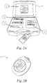
- Fig. 2A shows an example kit comprising the apparatus for mapping the trajectory of a part of the anatomy of the human or animal body shown in Fig. 1 .
- Fig. 2A shows a controller 1, two sensors 2, two straps 3 and an accessories compartment 4 optionally comprising accessories such as charging leads, all contained within a case 5.
- the controller 1 is a tablet, but it will be understood that the controller 1 could easily by any other computing device and may simply be a processor operable to receive sensor signals, determine angles of rotation from the sensor signals and transform the sensor signals to provide two-dimensional coordinate data.
- the case 5 is padded, for example with foam, to protect the contents of the case 5 when in transit. Providing the apparatus in a case 5 like this advantageously increases the ease of use and portability of the apparatus.
- the sensor 2 of Fig. 2A is shown in more detail in Fig. 2B .
- the sensor 2 has a unique combination of soft touch, non-marking polymers impregnated with germ-killing silver ion technology in a compact and wearable form factor.
- the sensor 2 is small, for example less than 50 x 50 x 50 mm, for example 48 x 38 x 24 mm and lightweight, for example less than 100g, for example less than 25g, for example 21g.
- the sensor 2 is also shock resistant, for example resistant to at least 4G, for example at least 10G, for example at least 32G.
- the housing of the sensor may contain Biomaster®, an effective, silver-based anti-microbial technology. Biomaster® is a broad spectrum anti-microbial additive independently tested and proven to reduce bacterial growth by 99.99% within 2 hours, providing durable, lifelong protection against the threat of cross-contamination.
- the sensor 2 is configured to be attached to a part of the anatomy of the human or animal body, for example as shown in Fig. 3 .
- the sensor 2 may comprise a strap, or means for attaching to a strap, that fastens around a limb of the human or animal body, for example an arm or a leg.
- the sensor 1 may comprise means to attach to clothing worn on the part of the anatomy, for example the sensor 1 may comprise a clip or hook and loop material.
- the sensor 2 is operable to communicate with the controller 1 to map the trajectory of a part of the anatomy of the human or animal body.
- the sensor 2 is configured to communicate wirelessly with the controller 1.
- the sensor 2 is configured to obtain three dimensional position information indicating the location of the sensor 2, and is operable to transmit this information as first sensor signals to the controller 1.
- the sensor 2 is configured to obtain the three dimensional position information based on information obtained from sensor elements 23, for example three dimensional position information selected from the list of: orientation relative to the earth's magnetic field, orientation relative to the direction of gravity, and ambient air pressure.
- the processor 21 of sensor 2 is operable to process information from the sensor elements 23 and via wireless communications interface 19, is operable to produce first sensor signals comprising three dimensional position information indicating the location of the sensor 2.
- the controller 1 is configured to receive these first sensor signals comprising the three dimensional position information indicating the location of the sensor 2 from the sensor 2, and the controller 1 is operable to determine at least two angles of rotation of a part of the anatomy of the human or animal body, for example at least two of pitch, yaw and roll as shown in Fig. 3 .
- the controller 1 may be running proprietary software that allows it to perform these functions.
- the controller 1 is operable to transform the signals received from the sensor 2 to provide two dimensional coordinate data defined in a two dimensional coordinate space such that a first dimension in the two dimensional coordinate space represents a first angle of rotation of the part of the anatomy and a second dimension in the two dimensional coordinate space represents a second angle of rotation of the part of the anatomy.
- the controller 1 is configured to store the two dimensional data, for example the controller 1 may be coupled to a data storage for storing the two dimensional data.
- the two dimensional coordinate data may be stored in a tabular format, for example as an XML file.
- the two dimensional coordinate space may comprise linear coordinate system, for example a rectilinear coordinate system.
- the controller 1 is operable to map the first sensor signals to an image space for display of the trajectory of the part of the anatomy, for example on display 15.
- the image space may comprise instructions for interpretation of data into an image format, for example the image space may be machine readable instructions for display of an image.
- the image space may comprise data formatted for display in an image, for example a file format, for example a jpg, png or tiff file format.
- the controller is operable to map the two dimensional coordinate data to an image space for display of the trajectory of the part of the anatomy, for example the controller is operable to map the stored two dimensional coordinate data to an image space.
- the two dimensional coordinate space may be an image space, such that when the two dimensional coordinate data is transformed to the two dimensional coordinate space it is simultaneously in an image space.
- the controller 1 is further operable to obtain a second sensor signal indicative of a third angle of rotation of the part of the anatomy, and is operable to store an association comprising the third angle of rotation and the two dimensional coordinate data indicating the at least two angles of rotation at which the second sensor signal was obtained.
- the third angle of rotation may comprise the degree of roll of the part of the anatomy.
- the controller 1 may be configured to map the third angle of rotation of the part of the anatomy to a display location in an image space, for example the same image space, selected based on the stored association.
- the controller 1 may be configured to display the third angle of rotation of the part of the anatomy as an overlay at the display location on a display of the trajectory of the part of the anatomy.
- the controller 1 is further operable to receive a third sensor signal comprising information indicative of an incidence point.
- the third sensor signal may be obtained from the sensor 2 and operated by the patient, for example from a user operable interface, for example via the use of a button, and may be obtained from the same sensor as the sensor providing the first sensor signals, or from another sensor, for example a sensor operated by a clinician/physiotherapist.
- the controller 1 may be configured to associate the incidence point with the at least two angles of rotation, for example the two dimensional coordinate data indicating the at least two angles of rotation of the part of the anatomy to record the location of the incidence point.
- the controller 1 may be configured to store this association between the incidence point and the two dimensional coordinate data.
- the controller 1 may be configured to map the incidence point to a display location in an image space, for example the same image space, selected based on the stored association. For example, the controller 1 may be configured to display the incidence point as an overlay at the display location on a display of the trajectory of the part of the anatomy.
- the controller 1 is further operable to receive a fourth sensor signal comprising information indicative of at least one selected from the list of: speed, acceleration and power of a part of the anatomy of the human or animal body.
- the sensor signals may be obtained from the sensor 2 and thus obtained from the same sensor providing the first sensor signals, or from another sensor, for example another sensor attached to the patient or a sensor operated by a clinician/physiotherapist.
- the sensor providing the fourth sensor signals may be the same as the sensor providing the third sensor signals.
- the controller 1 may be configured to associate the fourth sensor signals with the at least two angles of rotation, for example the two dimensional coordinate data indicating the at least two angles of rotation.
- the controller 1 may be configured to store this association between the fourth sensor signals, for example at least one selected from the list of: speed, acceleration and power of a part of the anatomy of the human or animal body and the two dimensional coordinate data.
- the controller 1 may be configured to map the speed, acceleration and/or power to a display location in an image space, for example the same image space, selected based on the stored association.
- the controller 1 may be configured to display the speed, acceleration and/or power as an overlay at the display location on a display of the trajectory of the part of the anatomy.
- the senor 2 is operable to transmit live data, for example the sensor signals, over a wireless connection, for example a Bluetooth® connection, to the controller 1.
- a wireless connection for example a Bluetooth® connection
- the sensor 2 may be operable to transmit the sensor signals to any controller within range, which is typically 10-25m for a Bluetooth® connection.
- the wireless connection between the controller 1 and sensor 2 is automatic and can detect any sensor 2 within range.
- a plurality of sensors 2, for example two sensors 2 may be connected at the same time enabling real-time direct comparison of data or activities.
- the senor 2 is operable to transmit at a frequency of at least 10 Hz, for example at least 50 Hz, for example at least 100 Hz with latency (delay) for the data (for example the first sensor signals comprising the three dimensional position information) being at least 8 ms, for example at most 40 ms, i.e. about 1/40th of a second.
- delay delay
- the controller 1 to focus on displaying actual figures in real time, for live feedback, as well as saving the results to a data storage for future reference and comparison.
- the senor 2 is configured to be uniquely identified and paired to the controller 1 using a licence key, for example the sensor 2 is configured to work with a specific controller 1.
- cloud data services such as Dropbox®
- patient mapping results can be easily shared across multiple machines in multiple locations, enabling mapping to be carried out at one location and the results reviewed at another location in real time.
- the controller 1 may use highly-complex mathematical algorithms to interpret the first sensor signals, and to transform them to map the trajectory of the part of the anatomy to which sensor 2 is attached.
- the senor 2 is operable in a number of different modes of operation.
- the sensor 2 may be operable in "find” mode, "calibration” mode, "mapping” mode or “sleep” mode.
- the mode of operation may be displayed somewhere on the sensor, for example the mode of operation may be indicated by a light on the sensor 2, for example a flashing LED. The light may also indicate when the sensor 2 is being charged up or requires charging.
- the senor 2 and the controller 1 are both switched on and communicating with each other such that signals sent from the sensor 2 are received by the controller 1.
- the sensor 2 and controller 1 may be communicating in a "mapping" mode where they are operated such that three dimensional position information indicating the location of the sensor 2 is transmitted to the controller 1.
- the sensor 2 is worn by a patient on a part of their anatomy, for example a limb, for example their arm.
- the patient and/or clinician/physiotherapist can start a mapping, for example by operating the controller 1 or by pressing a button on the sensor 2.
- the mapping begins, the patient moves their part of the anatomy across its range of motion. For example, if the patient is standing upright, the patient may move their arm from right to left and up and down, for example in an arc motion.
- the mapping may end for example when the patient has reached the limit of their range of motion, after a selected time has elapsed, or when a button, for example a button on sensor 2 or on another sensor operated by a patient and/or a clinician/physiotherapist, is pressed.
- the sensor elements 23 of the sensor 2 will provide three dimensional position information indicating the location of the sensor 2.
- the sensor elements 23 may obtain information comprising at least one of: orientation relative to gravity, orientation relative to the earth's magnetic field and air pressure.
- the processor 21 of sensor 2 processes this information and transmits it to the controller 1 via the wireless communications interface 19 as first sensor signals.
- the wireless communications interface 9 of the controller 1 receives the first sensor signals, and the controller 1, and specifically the processor of controller 1, transforms the first sensor signals to provide two dimensional coordinate data defined in a two dimensional coordinate space, wherein a first dimension in the two dimensional coordinate space represents a first angle of rotation of the part of the anatomy, and a second dimension in the two dimensional coordinate space represents a second angle of rotation of the part of the anatomy.
- the sensor elements 23 detect these movements, for example changes in orientation relative to gravity, changes in orientation relative to the earth's magnetic field and/or changes in air pressure, and the processor 21 of sensor 2 processes this three dimensional position information and sends it as first sensor signals via the wireless communications interface 19 for receipt by the wireless communications interface 9 of the controller 1.
- the sensor 2 continually outputs first sensor signals to the controller 1, for example regardless of whether the three dimensional position information has changed or not. In other configurations, the sensor 2 only outputs first sensor signals when a change in the three dimensional position information has occurred.
- the controller 1 transforms the first sensor signals to provide two dimensional coordinate data defined in a two dimensional coordinate space, wherein a first dimension in the two dimensional coordinate space represents a first angle of rotation of the part of the anatomy, and a second dimension in the two dimensional coordinate space represents a second angle of rotation of the part of the anatomy.
- the controller 1 then stores the two dimensional coordinate data, for example on an optional data storage coupled to the controller 1 or in some form of data storage comprised in controller 1.
- the two dimensional coordinate space is a linear two dimensional coordinate space, for example a rectilinear coordinate system.
- the controller 1 maps the first sensor signals to an image space for display of the trajectory of the part of the anatomy.
- the controller 1 may map the sensor signals to the image space in real time, or near real-time (for example with a delay less than 5 seconds, for example less than 2 seconds, for example less than 1 second from when the movement occurred or from when the signals are received by the controller 1).
- the controller 1 when the controller 1 transforms the first sensor signals to provide two dimensional coordinate data, the controller 1 also maps the first sensor signals to an image space for display of the part of the anatomy, for example on display 15.
- the two dimensional coordinate space may also be an image space.
- the controller 1 maps the two dimensional coordinate data to an image space for display of the part of the anatomy, for example on display 15. For example, in some configurations the controller 1 maps stored two dimensional coordinate data to an image space. In other configurations, the controller 1 maps the two dimensional coordinate data to an image space in real time and simultaneously stores the two dimensional coordinate data.
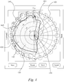
- the image space may be in the form of a plot, as shown in Fig. 4 .
- the plot shown in Fig. 4 represents an example mapping of the trajectory of an arm to an image space displayed on display 15 of controller 1.
- the mapping to an image space is in the form of a plot.
- the plot has two dimensions - one dimension 101 represents one angle of rotation (for example pitch) of the arm, and the other dimension 103 represents another angle of rotation (for example yaw) of the arm.
- the plot is stereographic in nature, that is the three dimensional position information is displayed on a two dimensional plot, and is conformal in that the angles are preserved.
- the dimension 101 representing pitch is Cartesian, with the relative orientations of the patient's arm with respect to another part of the body, in this case the patient's torso, indicated on the axes.
- the dimension 103 representing the yaw of the patient's arm is polar in nature; that is the angle of yaw increases with increasing distance from the centre or origin of the plot.
- the two dimensions are configured to line up so that 0 degrees of pitch and 0 degrees of yaw intersect at the centre or origin 150 of the plot.
- the plot will be at the origin of the plot.
- the complete plot shows a characteristic "D" profile.
- Fig. 4 shows the results of a previous mapping shown as an outline 130 overlaid on the plot of the current mapping.
- the mapped trajectory of at least one previous mapping can be mapped to an image space, wherein the two dimensional coordinate space and/or image space is the same as for at least one other mapping, and the mapped trajectory of at least one previous mapping can be overlaid on a display of the trajectory of the part of the anatomy from at least one other mapping, for example from stored two dimensional coordinate data.
- comparative and differential analysis is used to highlight how different parts of the anatomy of the patient's body, or how different patients are performing at the same time. For example the performance of the left arm can be compared to the right arm, or active use (where the patient is moving their body unaided) compared against passive use (where the clinician/physiotherapist is moving the arm).
- Patient data may be stored locally, for example on optional data storage coupled to the controller 1, enabling treatment and performance trends to be analysed and compared during and after live mapping.
- the mapped trajectory is compared to "standard” data, for example a "standard” range of motion.
- the "standard" range figures may be based, for example, on an average 40-year-old man.
- the controller 1 may be configured to display a warning "out" on display 15, and the mapping restarted. This is to protect the patient from hyperextension and from the mapping being performed incorrectly.
- An alternative "advanced" range may be used for other patients, for example for use with elite athletes who will likely have an increased range of motion.
- the controller 1 may be configured to map the third angle of rotation of the part of the anatomy to a display location in an image space selected based on the stored association, as shown by the dotted circles 140 in Fig. 4 .
- the dotted circles 140 are overlaid on the outer edge of the plot and indicate a third angle of rotation of the arm at that display location, in this case the roll.
- the shaded area in the overlaid plots 140 indicate the range of motion for that angle of rotation for that particular combination of the other two angles of rotation at that display location.
- the controller 1 In configurations where the controller 1 is operable to obtain a third sensor signal comprising information indicative of an incidence point, the controller 1, following receipt of a third sensor signal, stores an association between the incidence point and the two dimensional coordinate data indicating the at least two angles of rotation of the part of the anatomy to record the location of the incidence point.
- the incidence point may be mapped to a display location in an image space selected based on the stored association, for example so that the incidence point is displayed as an overlay at the display location on a display of the trajectory of the part of the anatomy.
- the clinician/physiotherapist and/or patient can mark Patient Incidence Points (PIPs) during the mapping to flag any issues arising such as pain or discomfort.
- PIPs Patient Incidence Points
- PIPs can be marked using, for example a user-operable interface, for example a button or by squeezing the sensor, and this may be confirmed by an audible click.
- the controller 1 is configured to map the PIPs to the image space such that they appear as an overlay on the plot, for example as an overlay on the mapped trajectory of the part of the anatomy, for example as diamonds 145 overlaid on the plot of the trajectory as shown in Fig. 4 .
- an unlimited number of PIPs can be marked and recorded.
- the controller 1 is further operable to receive a fourth sensor signal comprising information indicative of at least one of: speed, acceleration or power of a part of the anatomy of the human or animal body.
- the fourth sensor signals may be obtained from the sensor 2 and thus obtained from the same sensor providing the first sensor signals, or from another sensor, for example a sensor attached to the patient or a sensor operated by a clinician/physiotherapist.
- the sensor 2 may be used to map the trajectory of a cricketer's arm as he throws a cricket ball.
- the sensor 2 may be configured to obtain information indicative of the acceleration of the cricketer's arm as it moves.
- the controller 1 may be configured to associate the fourth sensor signals with the at least two angles of rotation, for example the two dimensional coordinate data indicating the at least two angles of rotation.
- the controller 1 may be configured to store this association between the fourth sensor signals, for example at least one selected from the list of: speed, acceleration and power of a part of the anatomy of the human or animal body and the two dimensional coordinate data.
- the controller 1 may be configured to map this information to an image space, for example so that the information is displayed as an overlay at the display location on a display of the trajectory of the part of the anatomy.
- the speed may be indicated by a change in colour of the mapping of the trajectory of the part of the anatomy in the image space.
- the controller 1 is able to support a plurality of sensors 2, for example two sensors 2, for example allowing measurements of left and right limbs simultaneously.
- the controller 1 When two sensors 2 are communicating with the controller 1, the one on the left can be associated with the left-hand side of the body and the right-hand sensor can be associated with the right-hand side of the body.
- the active sensor 2 may be highlighted as the appropriate mapping is selected. If the sensors 2 are placed on the wrong sides of the body, they can be swapped over, for example by operation of the controller 1.
- the sensor 2 can initiate a mapping without the need to return to the controller 1. For example, if the sensor 2 has a user-operable interface, for example a button, and a mapping is not running, one long press on the button starts the mapping and if the mapping is running, one long press stops the mapping and the mapped trajectory is stored as two dimensional coordinate data.
- a mapping for example a button
- any specific data point - for example the three dimensional position information, the determined angles of rotation of the part of the anatomy, or the transformed two dimensional coordinate data - can be displayed in a results table 70 (as shown in Fig. 5 ), for example by clicking on a display location on the image space.
- the tabular information 70 may show details of the current, first and a selected previous mapping for comparative purposes.
- At least one of the three dimensional position information, the determined angles of rotation of the part of the anatomy, the transformed two dimensional coordinate data, the incidence points and the speed, acceleration and power may also be displayed with respect to an avatar 50.
- the two dimensional coordinate data is transformed to three dimensional coordinate data defined in a three dimensional coordinate space, and the sensor signals and/or the transformed three dimensional coordinate data mapped to an image space, so that a three dimensional representation of an avatar 50 may be displayed, for example displaying the avatar 50 moving its part of the anatomy, and thus displaying the trajectory of the part of the anatomy on the avatar 50.
- the trajectory of the part of the anatomy may be displayed in real time with the movements of the sensor 2.
- the first sensor signals may be transformed to two dimensional coordinate data defined in a two dimensional coordinate space wherein the two dimensions together only represent one angle of rotation of the part of the anatomy.
- the sensor signals and/or the transformed two dimensional coordinate data may be displayed on an avatar 50, for example as shown in Fig. 5 .
- the image of the avatar 50 in Fig. 5 shows a patient's arm moving, in this example, as they map the trajectory of their arm and hence determine the range of their shoulder abduction (thus only indicating one angle of rotation of the part of the anatomy).
- the patient's maximum ranges for both passive and active movement are indicated by the lines 205 (active) and lines 210 (passive). In this example, the patient is compared to the vertical position, defined as being perpendicular to the Earth's surface.
- sensor signals comprising three dimensional position information indicating the location of the sensor 2 are transformed by the controller 1 to provide three dimensional coordinate data defined in a three dimensional space, wherein one plane indicates a first angle of rotation and a second plane indicates a second angle of rotation.
- the three dimensional coordinate data may comprise two dimensional coordinate data indicating the at least two angles of rotation of the part of the anatomy.
- the sensor signals and/or the transformed three dimensional coordinate data may be mapped to an image space for display of the trajectory of the part of the anatomy.
- a three dimensional representation of an avatar 50 may be displayed, for example displaying the avatar 50 moving its part of the anatomy, and thus displaying the trajectory of the part of the anatomy.
- the trajectory of the part of the anatomy may be displayed in real time with the movements of the sensor 2.
- the image space may only show one plane of the three dimensional space, thus only indicating one angle of rotation of the part of the anatomy.
- controller 1 may also be displayed with respect to an avatar 50 in a similar way to that described for the first sensor signals described above.
- the controller 1 allows the outcome of each mapping to be displayed individually. Alternatively, the outcomes of an unlimited number of mappings can be averaged. The averaged data may then be displayed in a table 70 and/or on an avatar 50. In some configurations PIPs are not averaged as they are deemed to be absolute, the last recorded PIPs, therefore, are those shown on the avatar 50.
- the controller 1 may be configured to automatically print to a printer.
- the screen may print out as it appears on the display 15 and it is important to ensure that the page orientation of the printer is set up appropriately.
- the printout contains only limited patient information in line with data protection guidelines. A printer driver for a recommended printer is preloaded onto the controller 1.
- the controller 1 may be configure to provide "Print” and "Plot” functions so that the patient can leave with a printout of the results of their mapping and a graph of their progress.
- the plot function also provides clear information in relation to the need for evidence based outcomes.
- the avatar 50 acts as an aide-memoire of the exercise being performed and the progress chart provides encouragement to the patient to continue with their rehabilitation as they can clearly see and understand the impact of their treatment without having to understand medical terminology.
- the printout may either comprise the avatar 50 image or historical mapping data. Patient details such as age, height and weight may be recorded for future use and stored on a data storage coupled to the controller 1 for data protection reasons. This data may encrypted, for example so that it is usable only by the controller 1. Each record may be assigned a universally unique identification reference.
- a search function may enable the clinician/physiotherapist easily to find an existing record.
- the subject data may be stored against the patient's details to enable treatment and performance trends to be analysed and compared during and after live mapping.
- the patient's history can also be reviewed to see what mappings have been done in the past and a specific set of mappings recalled for analysis during the next live mapping. This enables the current mapping to be compared not only with the first mapping, but also against a set of selected mappings. Data may be saved as in XML format for each patient.
- the controller 1 in order for the controller 1 and sensor 2 to communicate with each other, the controller 1 needs to "find” the sensor 2. In order to do this, the sensor 2 and controller 1 are configured to run in "find” mode so that they begin to communicate with each (for example, the sensor 2 and controller 1 are "paired").
- the controller 1 and the sensor 2 need to be calibrated. This may be done using a "calibration" mode. Once the sensor 2 and the controller 1 are communicating with each other, the sensor 2 can be automatically calibrated by the controller 1 to begin calibration. To improve the calibration procedure, the sensor 2 may be rolled between the palms of a user's hands so that the sensor elements 23 in the sensor 2 experience a wide range of motion. Preferably the sensor 2 is moved in all directions as much as possible.
- the controller 1 and/or sensor 2 may operate in "sleep” mode, for example if neither device has been used for a selected period of time, for example at least five minutes, for example at least ten minutes. In “sleep” mode the controller 1 and/or sensor 2 may be quickly activated and switched into “calibration” mode but whilst consuming less power than in "calibration" mode.
- An example sensor 2 used in the apparatus and methods disclosed herein has been validated in clinical trials and found to be on a par with OMCS (Optical Motion Capture Systems). These trials compared a single sensor 2 placed at the centre of mass (CoM), lumbar L4, and four Qualisys® cameras. Acceleration, velocity and relative position were compared. The table below shows the results of sensor 2 indicated as BPMproTM compared based on a single axis result:
- the BPMproTM sensor 2 was also interrogated using LabVIEW® 2010 and compared against multi-sensor systems such as Pi-Node®, Xsens® and OPAL®. On the basis that a single BPMproTM sensor 2 was being compared to multi-camera and multi-sensor systems, the results proved to be not only very useable in a real world environment, but they also demonstrate the cost effectiveness of the methods and apparatus of the present disclosure.
- the processor 11 of the controller 1, and/or the processor 21 of the sensor 2 described herein may comprise a general purpose processor, which may be configured to perform a method according to any one of those described herein.
- the controller 1 and/or the sensor 2 and/or the processor 11 and/or the processor 21 may comprise digital logic, such as field programmable gate arrays, FPGA, application specific integrated circuits, ASIC, a digital signal processor, DSP, or any other appropriate hardware.
- processor or other programmable component
- this may be achieved by procedural or object oriented programming, or by the use of scripting which incorporates a mixture of both procedural and object oriented approaches.
- FGPAs or ASICs may be used to provide these configurations.
- the data stores described herein may be provided by volatile or involatile memory storage such as RAM, EEPROM, FLASH memory, or any other form of computer readable media.
Landscapes
- Health & Medical Sciences (AREA)
- Life Sciences & Earth Sciences (AREA)
- Physics & Mathematics (AREA)
- Engineering & Computer Science (AREA)
- Public Health (AREA)
- Surgery (AREA)
- Pathology (AREA)
- Biomedical Technology (AREA)
- Heart & Thoracic Surgery (AREA)
- Medical Informatics (AREA)
- Molecular Biology (AREA)
- Biophysics (AREA)
- Animal Behavior & Ethology (AREA)
- General Health & Medical Sciences (AREA)
- Veterinary Medicine (AREA)
- Physiology (AREA)
- Oral & Maxillofacial Surgery (AREA)
- Dentistry (AREA)
- Geometry (AREA)
- Radiology & Medical Imaging (AREA)
- Nuclear Medicine, Radiotherapy & Molecular Imaging (AREA)
- Computer Networks & Wireless Communication (AREA)
- Artificial Intelligence (AREA)
- Computer Vision & Pattern Recognition (AREA)
- Psychiatry (AREA)
- Signal Processing (AREA)
- Orthopedic Medicine & Surgery (AREA)
- Rheumatology (AREA)
- Measurement Of The Respiration, Hearing Ability, Form, And Blood Characteristics Of Living Organisms (AREA)
- User Interface Of Digital Computer (AREA)
Claims (15)
- Ein Verfahren zum Mapping der Bewegungsbahn eines Teils der Anatomie eines menschlichen oder tierischen Körpers, wobei das Verfahren Folgendes beinhaltet:Empfangen von ersten Sensorsignalen von einem an einem Teil der Anatomie des menschlichen oder tierischen Körpers angebrachten Sensor, wobei die ersten Sensorsignale dreidimensionale Positionsinformationen beinhalten, die den Ort des Sensors angeben;Bestimmen, aus den ersten Sensorsignalen, von mindestens zwei Rotationswinkeln des Teils der Anatomie, an dem der Sensor angebracht ist, bezüglich eines Rotationszentrums eines anderen Teils des Körpers, wobei die Rotationswinkel aus Nicken, Gieren und Rollen ausgewählt sind;Transformieren der Signale, um zweidimensionale Koordinatendaten bereitzustellen, die in einem zweidimensionalen Koordinatenraum definiert sind, wobei eine erste Dimension (101) in dem zweidimensionalen Koordinatenraum einen ersten Rotationswinkel des Teils der Anatomie darstellt, und eine zweite Dimension (103) in dem zweidimensionalen Koordinatenraum einen zweiten Rotationswinkel des Teils der Anatomie darstellt; undSpeichern der zweidimensionalen Koordinatendaten,wobei das Transformieren der Signale das Mapping der Signale auf einen Bildraum zum Anzeigen der Bewegungsbahn des Teils der Anatomie umfasst.
- Verfahren nach Anspruch 1, das Folgendes beinhaltet: Erhalten eines zweiten Sensorsignals, das einen dritten Rotationswinkel des Teils der Anatomie angibt, und Speichern einer Assoziation, die (i) den dritten Rotationswinkel und (ii) die zweidimensionalen Koordinatendaten beinhaltet, die die mindestens zwei Rotationswinkel angeben, bei denen das zweite Sensorsignal erhalten wurde, optional beinhaltend das Mapping des dritten Rotationswinkels auf einem auf der Grundlage der gespeicherten Assoziation ausgewählten Anzeigeort in einem Bildraum, optional ferner beinhaltend das Anzeigen des dritten Rotationswinkels des Teils der Anatomie als eine Überlagerung (140) an dem Anzeigeort auf einer Anzeige der Bewegungsbahn des Teils der Anatomie.
- Verfahren nach einem der vorhergehenden Ansprüche, wobei das Transformieren der Signale das Transformieren der Signale zu einem linearen zweidimensionalen Koordinatenraum, zum Beispiel einem kartesischen Raum, beinhaltet, wobei das Transformieren der Signale zu einem linearen zweidimensionalen Koordinatenraum optional mindestens eines der Folgenden beinhaltet: (i) eine konforme Transformation und (ii) Anwenden einer stereographischen Projektion.
- Verfahren nach einem der vorhergehenden Ansprüche, das ferner Folgendes beinhaltet:Empfangen, von einem Sensor, eines dritten Sensorsignals, das Informationen beinhaltet, die einen Einfallspunkt (145) angeben; undSpeichern einer Assoziation zwischen dem Einfallspunkt und den zweidimensionalen Koordinatendaten, die die mindestens zwei Rotationswinkel des Teils der Anatomie angeben, um den Ort des Einfallspunkts aufzuzeichnen.
- Verfahren nach Anspruch 4, das ferner das Mapping des Einfallspunkts auf einem auf der Grundlage der gespeicherten Assoziation ausgewählten Anzeigeort in einem Bildraum beinhaltet, optional ferner beinhaltend das Anzeigen des Einfallspunkts als eine Überlagerung (145) an dem Anzeigeort auf einer Anzeige der Bewegungsbahn des Teils der Anatomie.
- Verfahren nach einem der vorhergehenden Ansprüche, das ferner Folgendes beinhaltet:Empfangen von vierten Sensorsignalen, die Informationen beinhalten, die mindestens eines von der Geschwindigkeit, Beschleunigung oder Kraft eines Teils der Anatomie des menschlichen oder tierischen Körpers angeben;und Assoziieren der vierten Sensorsignale mit den mindestens zwei Rotationswinkeln des Teils der Anatomie, um mindestens eines von der Geschwindigkeit, Beschleunigung oder Kraft als Funktion der mindestens zwei Rotationswinkel des Teils der Anatomie aufzuzeichnen.
- Verfahren nach Anspruch 6, das ferner das Mapping von mindestens einem von der Geschwindigkeit, Beschleunigung oder Kraft auf einem Bildraum beinhaltet, um die Funktion als eine Überlagerung auf einer Anzeige der Bewegungsbahn des Teils der Anatomie anzuzeigen.
- Verfahren nach einem der vorhergehenden Ansprüche, das ferner Folgendes beinhaltet: Mapping der ersten Sensorsignale auf einem Bildraum und Mapping gespeicherter zweidimensionaler Koordinatendaten auf dem Bildraum zum Anzeigen der Bewegungsbahn des Teils der Anatomie als eine Überlagerung (130) auf einer Anzeige der zu dem Bildraum gemappten Bewegungsbahn des Teils der Anatomie von den gespeicherten zweidimensionalen Koordinatendaten.
- Eine Vorrichtung zum Mappen der Bewegungsbahn eines Teils der Anatomie eines menschlichen oder tierischen Körpers, wobei die Vorrichtung Folgendes beinhaltet:einen Sensor (23) zum Anbringen an einem Teil der Anatomie des menschlichen oder tierischen Körpers;und einen Prozessor (11) zum Empfangen von ersten Sensorsignalen von dem Sensor, wobei die ersten Sensorsignale dreidimensionale Positionsinformationen beinhalten, die den Ort des Sensors angeben;wobei der Prozessor (11) dazu ausgelegt ist, mindestens zwei Rotationswinkel des Teils der Anatomie des menschlichen oder tierischen Körpers, an dem er angebracht ist, bezüglich eines Rotationszentrums des Körpers zu bestimmen, wobei die Rotationswinkel aus Nicken, Gieren und Rollen ausgewählt sind; undder Prozessor (11) dazu ausgelegt ist, die ersten von dem Sensor erhaltenen Sensorsignale zu transformieren, um zweidimensionale Koordinatendaten bereitzustellen, die in einem zweidimensionalen Koordinatenraum definiert sind, sodass eine erste Dimension (101) in dem zweidimensionalen Koordinatenraum einen ersten Rotationswinkel des Teils der Anatomie darstellt und eine zweite Dimension (103) in dem zweidimensionalen Koordinatenraum einen zweiten Rotationswinkel des Teils der Anatomie darstellt, und um die zweidimensionalen Koordinatendaten zu speichern,wobei der Prozessor (11) dazu ausgelegt ist, die ersten Sensorsignale zum Anzeigen der Bewegungsbahn des Teils der Anatomie auf einem Bildraum zu mappen.
- Vorrichtung nach Anspruch 9, wobei der Prozessor (11) ferner dazu ausgelegt ist, ein zweites Sensorsignal zu erhalten, das einen dritten Rotationswinkel des Teils der Anatomie angibt, und eine Assoziation zu speichern, die (i) den dritten Rotationswinkel und (ii) die zweidimensionalen Koordinatendaten beinhaltet, die die mindestens zwei Rotationswinkel, bei denen das zweite Sensorsignal erhalten wurde, angeben, wobei der Prozessor (11) ferner optional dazu ausgelegt ist, den dritten Rotationswinkel auf einem auf der Grundlage der gespeicherten Assoziation ausgewählten Anzeigeort in einem Bildraum zu mappen, und der Prozessor (11) optional dazu ausgelegt ist, den dritten Rotationswinkel des Teils der Anatomie als eine Überlagerung (140) an dem Anzeigeort auf einer Anzeige der Bewegungsbahn des Teils der Anatomie anzuzeigen.
- Vorrichtung nach Anspruch 9 oder 10, wobei der Prozessor (11) dazu ausgelegt ist, die empfangenen Signale zu einem linearen zweidimensionalen Koordinatenraum, zum Beispiel einem kartesischen Raum, zu transformieren, wobei der Prozessor (11) optional dazu ausgelegt ist, die empfangenen Signale über mindestens eines der Folgenden zu transformieren: (i) eine konforme Transformation und (ii) eine stereografische Projektion.
- Vorrichtung nach einem der Ansprüche 9 bis 11, die ferner Folgendes beinhaltet:einen Sensor zum Angeben eines Einfallspunkts; wobeider Prozessor (11) dazu ausgelegt ist, ein drittes Sensorsignal zu empfangen, das Informationen beinhaltet, die den Einfallspunkt (145) angeben, und eine Assoziation zwischen dem Einfallspunkt und den zweidimensionalen Koordinatendaten zu speichern, die die mindestens zwei Rotationswinkel des Teils der Anatomie angeben, um den Ort des Einfallspunkts aufzuzeichnen.
- Vorrichtung nach Anspruch 12, wobei der Prozessor (11) dazu ausgelegt ist, das dritte Sensorsignal zum Anzeigen des Einfallspunkts (145) an einem auf der Grundlage der gespeicherten Assoziation ausgewählten Anzeigeort auf einem Bildraum zu mappen.
- Vorrichtung nach Anspruch 13, wobei der Prozessor (11) dazu ausgelegt ist, den Einfallspunkt (145) als eine Überlagerung auf einer Anzeige der Bewegungsbahn des Teils der Anatomie anzuzeigen.
- Vorrichtung nach einem der Ansprüche 9 bis 14, wobei der Prozessor (11) dazu ausgelegt ist, vierte Sensorsignale zu empfangen, die Informationen beinhalten, die mindestens eines von der Geschwindigkeit, Beschleunigung oder Kraft eines Teils der Anatomie des menschlichen oder tierischen Körpers angeben, und wobei der Prozessor (11) dazu ausgelegt ist, die vierten Signale mit den mindestens zwei Rotationswinkeln des Teils der Anatomie zu assoziieren, um mindestens eines von der Geschwindigkeit, Beschleunigung oder Kraft als eine Funktion der mindestens zwei Rotationswinkel des Teils der Anatomie aufzuzeichnen.
Priority Applications (1)
| Application Number | Priority Date | Filing Date | Title |
|---|---|---|---|
| EP21174440.4A EP3888536A1 (de) | 2014-09-30 | 2015-09-29 | Abbildung der flugbahn eines teils der anatomie des menschlichen oder tierischen körpers |
Applications Claiming Priority (2)
| Application Number | Priority Date | Filing Date | Title |
|---|---|---|---|
| GB1417282.9A GB2530754B (en) | 2014-09-30 | 2014-09-30 | Mapping the trajectory of a part of the anatomy of the human or animal body |
| PCT/GB2015/052836 WO2016051162A1 (en) | 2014-09-30 | 2015-09-29 | Mapping the trajectory of a part of the anatomy of the human or animal body |
Related Child Applications (2)
| Application Number | Title | Priority Date | Filing Date |
|---|---|---|---|
| EP21174440.4A Division EP3888536A1 (de) | 2014-09-30 | 2015-09-29 | Abbildung der flugbahn eines teils der anatomie des menschlichen oder tierischen körpers |
| EP21174440.4A Division-Into EP3888536A1 (de) | 2014-09-30 | 2015-09-29 | Abbildung der flugbahn eines teils der anatomie des menschlichen oder tierischen körpers |
Publications (2)
| Publication Number | Publication Date |
|---|---|
| EP3200693A1 EP3200693A1 (de) | 2017-08-09 |
| EP3200693B1 true EP3200693B1 (de) | 2021-07-07 |
Family
ID=51901390
Family Applications (2)
| Application Number | Title | Priority Date | Filing Date |
|---|---|---|---|
| EP21174440.4A Withdrawn EP3888536A1 (de) | 2014-09-30 | 2015-09-29 | Abbildung der flugbahn eines teils der anatomie des menschlichen oder tierischen körpers |
| EP15791335.1A Active EP3200693B1 (de) | 2014-09-30 | 2015-09-29 | Abbildung der flugbahn eines teils der anatomie des menschlichen oder tierischen körpers |
Family Applications Before (1)
| Application Number | Title | Priority Date | Filing Date |
|---|---|---|---|
| EP21174440.4A Withdrawn EP3888536A1 (de) | 2014-09-30 | 2015-09-29 | Abbildung der flugbahn eines teils der anatomie des menschlichen oder tierischen körpers |
Country Status (5)
| Country | Link |
|---|---|
| US (2) | US10561346B2 (de) |
| EP (2) | EP3888536A1 (de) |
| JP (1) | JP2017529929A (de) |
| GB (2) | GB2530754B (de) |
| WO (1) | WO2016051162A1 (de) |
Families Citing this family (7)
| Publication number | Priority date | Publication date | Assignee | Title |
|---|---|---|---|---|
| WO2018087853A1 (ja) * | 2016-11-09 | 2018-05-17 | 株式会社システムフレンド | 立体画像生成システム、立体画像生成方法及び立体画像生成プログラム |
| EP3533390A1 (de) * | 2018-02-28 | 2019-09-04 | Koninklijke Philips N.V. | Rehabilitationssystem und verfahren |
| GB2582632B (en) * | 2019-03-28 | 2021-07-21 | 270 Vision Ltd | A system and method for improving the range of motion of a patient |
| GB202009759D0 (en) | 2020-06-26 | 2020-08-12 | Agile Kinetic Ltd | Method of monitoring mobility |
| JP7631893B2 (ja) * | 2021-03-01 | 2025-02-19 | 日本電気株式会社 | 情報出力装置、情報出力方法及びプログラム |
| JP2025072244A (ja) * | 2023-10-24 | 2025-05-09 | トヨタ自動車株式会社 | 動作状態監視システム、その制御方法、及び、制御プログラム |
| JP2025072243A (ja) * | 2023-10-24 | 2025-05-09 | トヨタ自動車株式会社 | 動作状態監視システム、動作状態監視方法、及び、動作状態監視プログラム |
Citations (1)
| Publication number | Priority date | Publication date | Assignee | Title |
|---|---|---|---|---|
| US20140135744A1 (en) * | 2012-11-09 | 2014-05-15 | Orthosensor Inc | Motion and orientation sensing module or device for positioning of implants |
Family Cites Families (35)
| Publication number | Priority date | Publication date | Assignee | Title |
|---|---|---|---|---|
| JPS60195613A (ja) * | 1984-03-16 | 1985-10-04 | Hitachi Ltd | 検証機能付ロボツト教示装置 |
| GB8521547D0 (en) | 1985-08-29 | 1985-10-02 | British Petroleum Co Plc | Production of esters |
| US5645077A (en) * | 1994-06-16 | 1997-07-08 | Massachusetts Institute Of Technology | Inertial orientation tracker apparatus having automatic drift compensation for tracking human head and other similarly sized body |
| DE69611031T2 (de) * | 1996-03-19 | 2001-05-17 | Balance International Inc., Boulder | Verfahren und Vorrichtung für Gleichgewicht-Prothese |
| WO1998047426A1 (en) * | 1997-04-21 | 1998-10-29 | Virtual Technologies, Inc. | Goniometer-based body-tracking device and method |
| JP2002000584A (ja) * | 2000-06-16 | 2002-01-08 | Matsushita Electric Ind Co Ltd | 関節可動域検査訓練システム |
| US6567536B2 (en) * | 2001-02-16 | 2003-05-20 | Golftec Enterprises Llc | Method and system for physical motion analysis |
| US8010180B2 (en) * | 2002-03-06 | 2011-08-30 | Mako Surgical Corp. | Haptic guidance system and method |
| JP3660330B2 (ja) | 2002-08-13 | 2005-06-15 | 独立行政法人科学技術振興機構 | インピーダンス測定装置及び運動学習支援装置 |
| US20050223799A1 (en) * | 2004-03-31 | 2005-10-13 | Brian Murphy | System and method for motion capture and analysis |
| JP2006020780A (ja) | 2004-07-07 | 2006-01-26 | Nec Tokin Corp | 四肢訓練装置 |
| US20060036163A1 (en) | 2004-07-19 | 2006-02-16 | Viswanathan Raju R | Method of, and apparatus for, controlling medical navigation systems |
| JP4734559B2 (ja) | 2004-12-02 | 2011-07-27 | 大学共同利用機関法人情報・システム研究機構 | 時系列データ分析装置および時系列データ分析プログラム |
| WO2007008930A2 (en) * | 2005-07-13 | 2007-01-18 | Ultimate Balance, Inc. | Orientation and motion sensing in athletic training systems, physical rehabilitation and evaluation systems, and hand-held devices |
| JP5226181B2 (ja) | 2005-11-24 | 2013-07-03 | ジーイー・メディカル・システムズ・グローバル・テクノロジー・カンパニー・エルエルシー | 画像診断装置 |
| US8626472B2 (en) * | 2006-07-21 | 2014-01-07 | James C. Solinsky | System and method for measuring balance and track motion in mammals |
| US9597015B2 (en) * | 2008-02-12 | 2017-03-21 | Portland State University | Joint angle tracking with inertial sensors |
| KR101483713B1 (ko) * | 2008-06-30 | 2015-01-16 | 삼성전자 주식회사 | 모션 캡쳐 장치 및 모션 캡쳐 방법 |
| US20110218462A1 (en) * | 2009-10-27 | 2011-09-08 | Smith Malcolm J | System for Measurement and Analysis of Movement of Anatomical Joints and/or Mechanical Systems |
| US9060714B2 (en) * | 2008-12-04 | 2015-06-23 | The Regents Of The University Of California | System for detection of body motion |
| EP2199948A1 (de) * | 2008-12-18 | 2010-06-23 | Koninklijke Philips Electronics N.V. | Verfahren zum Zeichnen einer 3D-Bewegung in einem 1D-Grafen und zum Vergleichen von zwei willkürlichen 3D-Bewegungen |
| WO2010120687A1 (en) * | 2009-04-13 | 2010-10-21 | Humanhuman Technologies, Inc. | Game controller simulating parts of the human anatomy |
| DE102009019242B4 (de) * | 2009-04-30 | 2014-09-11 | Technische Universität Carolo-Wilhelmina Zu Braunschweig | Medizinisches Diagnosegerät sowie Verfahren zur Bestimmung einer ortsaufgelösten Bildinformation |
| CA2698078A1 (en) * | 2010-03-26 | 2011-09-26 | Applied Technology Holdings, Inc. | Apparatus, systems and methods for gathering and processing biometric and biomechanical data |
| FR2959112B1 (fr) * | 2010-04-23 | 2015-05-29 | Movea | Systeme d'analyse de foulees d'un utilisateur |
| US9706948B2 (en) * | 2010-05-06 | 2017-07-18 | Sachin Bhandari | Inertial sensor based surgical navigation system for knee replacement surgery |
| EP2452649A1 (de) * | 2010-11-12 | 2012-05-16 | Deutsches Krebsforschungszentrum Stiftung des Öffentlichen Rechts | Visualisierung anatomischer Daten mittels erweiterter Realität |
| US8928671B2 (en) * | 2010-11-24 | 2015-01-06 | Fujitsu Limited | Recording and analyzing data on a 3D avatar |
| US20130293362A1 (en) * | 2012-05-03 | 2013-11-07 | The Methodist Hospital Research Institute | Multi-degrees-of-freedom hand controller |
| TWI549655B (zh) * | 2012-05-18 | 2016-09-21 | 國立成功大學 | 關節活動度量測裝置及其量測方法 |
| CA2890698A1 (en) * | 2012-11-09 | 2014-05-15 | Dorsavi Pty Ltd | Method and apparatus for monitoring deviation of a limb |
| TWI459247B (zh) | 2012-11-14 | 2014-11-01 | Univ Nat Central | 運動軌跡重建系統及運動軌跡重建方法 |
| JP6181373B2 (ja) | 2013-01-18 | 2017-08-16 | 東芝メディカルシステムズ株式会社 | 医用情報処理装置及びプログラム |
| US9173596B1 (en) * | 2014-06-28 | 2015-11-03 | Bertec Limited | Movement assessment apparatus and a method for providing biofeedback using the same |
| WO2016044651A1 (en) * | 2014-09-17 | 2016-03-24 | Canary Medical Inc. | Devices, systems and methods for using and monitoring medical devices |
-
2014
- 2014-09-30 GB GB1417282.9A patent/GB2530754B/en active Active
- 2014-09-30 GB GB1704148.4A patent/GB2551238B/en active Active
-
2015
- 2015-09-29 US US15/511,249 patent/US10561346B2/en active Active
- 2015-09-29 EP EP21174440.4A patent/EP3888536A1/de not_active Withdrawn
- 2015-09-29 WO PCT/GB2015/052836 patent/WO2016051162A1/en not_active Ceased
- 2015-09-29 EP EP15791335.1A patent/EP3200693B1/de active Active
- 2015-09-29 JP JP2017515985A patent/JP2017529929A/ja active Pending
-
2019
- 2019-12-13 US US16/713,040 patent/US11337623B2/en active Active
Patent Citations (1)
| Publication number | Priority date | Publication date | Assignee | Title |
|---|---|---|---|---|
| US20140135744A1 (en) * | 2012-11-09 | 2014-05-15 | Orthosensor Inc | Motion and orientation sensing module or device for positioning of implants |
Also Published As
| Publication number | Publication date |
|---|---|
| GB201704148D0 (en) | 2017-04-26 |
| GB201417282D0 (en) | 2014-11-12 |
| JP2017529929A (ja) | 2017-10-12 |
| GB2530754A (en) | 2016-04-06 |
| GB2551238A (en) | 2017-12-13 |
| EP3888536A1 (de) | 2021-10-06 |
| US11337623B2 (en) | 2022-05-24 |
| WO2016051162A1 (en) | 2016-04-07 |
| US20200113491A1 (en) | 2020-04-16 |
| GB2530754B (en) | 2017-05-03 |
| US20170251955A1 (en) | 2017-09-07 |
| GB2551238B (en) | 2019-04-10 |
| EP3200693A1 (de) | 2017-08-09 |
| US10561346B2 (en) | 2020-02-18 |
Similar Documents
| Publication | Publication Date | Title |
|---|---|---|
| US11337623B2 (en) | Mapping the trajectory of a part of the anatomy of the human or animal body | |
| Salchow-Hömmen et al. | A tangible solution for hand motion tracking in clinical applications | |
| JP6852673B2 (ja) | センサ装置、センサシステム及び情報処理装置 | |
| US9918663B2 (en) | Feedback wearable | |
| Brennan et al. | Quantification of inertial sensor-based 3D joint angle measurement accuracy using an instrumented gimbal | |
| JP5974668B2 (ja) | マニピュレーションシステム | |
| JP2020510511A5 (de) | ||
| WO2017021965A2 (en) | Body movement feedback system and method | |
| CN102245100A (zh) | 图形表示 | |
| JP2015061579A (ja) | 動作情報処理装置 | |
| CN103417217B (zh) | 关节活动度量测装置及其量测方法 | |
| JP6145072B2 (ja) | センサーモジュールの位置の取得方法及び装置、及び、動作計測方法及び装置 | |
| JP2020512074A (ja) | ユーザに対するハンドヘルド・パーソナルケアデバイスの位置及び/又は向きを推定するシステム、装置及び方法 | |
| GB2559717A (en) | Neurosurgical MRI-guided ultrasound via multi-modal image registration and multi-sensor fusion | |
| CN106901748A (zh) | 一种基于加速度传感器的关节活动度测量装置 | |
| JP2017176244A (ja) | 動的バランス評価装置 | |
| GB2566850A (en) | Mapping trajectories of the anatomy of the human or animal body for comparative analysis | |
| KR101501446B1 (ko) | 관성센서와 적외선 카메라를 이용한 보행 측정 장치. | |
| EP2943115A1 (de) | System und verfahren zur bewertung des bewegungsbereichs einer person | |
| JP6869417B1 (ja) | プログラム、方法、情報処理装置、システム | |
| WO2016014163A1 (en) | Three dimensional sensor-based interactive pain maps for localizing pain | |
| TWM512737U (zh) | 人體姿態感測裝置 | |
| JP7540814B1 (ja) | 転倒危険度判定装置 | |
| Hejda et al. | System for precise measurement of head and shoulders position | |
| Lyu | A Novel Wearable Technique for Back Support Exoskeletons Trunk Motion Detection and Payload Weight Estimation |
Legal Events
| Date | Code | Title | Description |
|---|---|---|---|
| STAA | Information on the status of an ep patent application or granted ep patent |
Free format text: STATUS: THE INTERNATIONAL PUBLICATION HAS BEEN MADE |
|
| PUAI | Public reference made under article 153(3) epc to a published international application that has entered the european phase |
Free format text: ORIGINAL CODE: 0009012 |
|
| STAA | Information on the status of an ep patent application or granted ep patent |
Free format text: STATUS: REQUEST FOR EXAMINATION WAS MADE |
|
| 17P | Request for examination filed |
Effective date: 20170317 |
|
| AK | Designated contracting states |
Kind code of ref document: A1 Designated state(s): AL AT BE BG CH CY CZ DE DK EE ES FI FR GB GR HR HU IE IS IT LI LT LU LV MC MK MT NL NO PL PT RO RS SE SI SK SM TR |
|
| AX | Request for extension of the european patent |
Extension state: BA ME |
|
| DAV | Request for validation of the european patent (deleted) | ||
| DAX | Request for extension of the european patent (deleted) | ||
| STAA | Information on the status of an ep patent application or granted ep patent |
Free format text: STATUS: EXAMINATION IS IN PROGRESS |
|
| 17Q | First examination report despatched |
Effective date: 20180405 |
|
| GRAP | Despatch of communication of intention to grant a patent |
Free format text: ORIGINAL CODE: EPIDOSNIGR1 |
|
| STAA | Information on the status of an ep patent application or granted ep patent |
Free format text: STATUS: GRANT OF PATENT IS INTENDED |
|
| INTG | Intention to grant announced |
Effective date: 20210129 |
|
| GRAS | Grant fee paid |
Free format text: ORIGINAL CODE: EPIDOSNIGR3 |
|
| GRAA | (expected) grant |
Free format text: ORIGINAL CODE: 0009210 |
|
| STAA | Information on the status of an ep patent application or granted ep patent |
Free format text: STATUS: THE PATENT HAS BEEN GRANTED |
|
| AK | Designated contracting states |
Kind code of ref document: B1 Designated state(s): AL AT BE BG CH CY CZ DE DK EE ES FI FR GB GR HR HU IE IS IT LI LT LU LV MC MK MT NL NO PL PT RO RS SE SI SK SM TR |
|
| REG | Reference to a national code |
Ref country code: GB Ref legal event code: FG4D |
|
| REG | Reference to a national code |
Ref country code: AT Ref legal event code: REF Ref document number: 1407775 Country of ref document: AT Kind code of ref document: T Effective date: 20210715 |
|
| REG | Reference to a national code |
Ref country code: DE Ref legal event code: R096 Ref document number: 602015071128 Country of ref document: DE |
|
| REG | Reference to a national code |
Ref country code: IE Ref legal event code: FG4D |
|
| REG | Reference to a national code |
Ref country code: LT Ref legal event code: MG9D |
|
| REG | Reference to a national code |
Ref country code: NL Ref legal event code: MP Effective date: 20210707 |
|
| REG | Reference to a national code |
Ref country code: AT Ref legal event code: MK05 Ref document number: 1407775 Country of ref document: AT Kind code of ref document: T Effective date: 20210707 |
|
| PG25 | Lapsed in a contracting state [announced via postgrant information from national office to epo] |
Ref country code: PT Free format text: LAPSE BECAUSE OF FAILURE TO SUBMIT A TRANSLATION OF THE DESCRIPTION OR TO PAY THE FEE WITHIN THE PRESCRIBED TIME-LIMIT Effective date: 20211108 Ref country code: NO Free format text: LAPSE BECAUSE OF FAILURE TO SUBMIT A TRANSLATION OF THE DESCRIPTION OR TO PAY THE FEE WITHIN THE PRESCRIBED TIME-LIMIT Effective date: 20211007 Ref country code: NL Free format text: LAPSE BECAUSE OF FAILURE TO SUBMIT A TRANSLATION OF THE DESCRIPTION OR TO PAY THE FEE WITHIN THE PRESCRIBED TIME-LIMIT Effective date: 20210707 Ref country code: FI Free format text: LAPSE BECAUSE OF FAILURE TO SUBMIT A TRANSLATION OF THE DESCRIPTION OR TO PAY THE FEE WITHIN THE PRESCRIBED TIME-LIMIT Effective date: 20210707 Ref country code: ES Free format text: LAPSE BECAUSE OF FAILURE TO SUBMIT A TRANSLATION OF THE DESCRIPTION OR TO PAY THE FEE WITHIN THE PRESCRIBED TIME-LIMIT Effective date: 20210707 Ref country code: LT Free format text: LAPSE BECAUSE OF FAILURE TO SUBMIT A TRANSLATION OF THE DESCRIPTION OR TO PAY THE FEE WITHIN THE PRESCRIBED TIME-LIMIT Effective date: 20210707 Ref country code: BG Free format text: LAPSE BECAUSE OF FAILURE TO SUBMIT A TRANSLATION OF THE DESCRIPTION OR TO PAY THE FEE WITHIN THE PRESCRIBED TIME-LIMIT Effective date: 20211007 Ref country code: AT Free format text: LAPSE BECAUSE OF FAILURE TO SUBMIT A TRANSLATION OF THE DESCRIPTION OR TO PAY THE FEE WITHIN THE PRESCRIBED TIME-LIMIT Effective date: 20210707 Ref country code: HR Free format text: LAPSE BECAUSE OF FAILURE TO SUBMIT A TRANSLATION OF THE DESCRIPTION OR TO PAY THE FEE WITHIN THE PRESCRIBED TIME-LIMIT Effective date: 20210707 Ref country code: RS Free format text: LAPSE BECAUSE OF FAILURE TO SUBMIT A TRANSLATION OF THE DESCRIPTION OR TO PAY THE FEE WITHIN THE PRESCRIBED TIME-LIMIT Effective date: 20210707 Ref country code: SE Free format text: LAPSE BECAUSE OF FAILURE TO SUBMIT A TRANSLATION OF THE DESCRIPTION OR TO PAY THE FEE WITHIN THE PRESCRIBED TIME-LIMIT Effective date: 20210707 |
|
| PG25 | Lapsed in a contracting state [announced via postgrant information from national office to epo] |
Ref country code: PL Free format text: LAPSE BECAUSE OF FAILURE TO SUBMIT A TRANSLATION OF THE DESCRIPTION OR TO PAY THE FEE WITHIN THE PRESCRIBED TIME-LIMIT Effective date: 20210707 Ref country code: LV Free format text: LAPSE BECAUSE OF FAILURE TO SUBMIT A TRANSLATION OF THE DESCRIPTION OR TO PAY THE FEE WITHIN THE PRESCRIBED TIME-LIMIT Effective date: 20210707 Ref country code: GR Free format text: LAPSE BECAUSE OF FAILURE TO SUBMIT A TRANSLATION OF THE DESCRIPTION OR TO PAY THE FEE WITHIN THE PRESCRIBED TIME-LIMIT Effective date: 20211008 |
|
| REG | Reference to a national code |
Ref country code: DE Ref legal event code: R097 Ref document number: 602015071128 Country of ref document: DE |
|
| PG25 | Lapsed in a contracting state [announced via postgrant information from national office to epo] |
Ref country code: DK Free format text: LAPSE BECAUSE OF FAILURE TO SUBMIT A TRANSLATION OF THE DESCRIPTION OR TO PAY THE FEE WITHIN THE PRESCRIBED TIME-LIMIT Effective date: 20210707 |
|
| REG | Reference to a national code |
Ref country code: CH Ref legal event code: PL |
|
| PLBE | No opposition filed within time limit |
Free format text: ORIGINAL CODE: 0009261 |
|
| STAA | Information on the status of an ep patent application or granted ep patent |
Free format text: STATUS: NO OPPOSITION FILED WITHIN TIME LIMIT |
|
| REG | Reference to a national code |
Ref country code: BE Ref legal event code: MM Effective date: 20210930 |
|
| PG25 | Lapsed in a contracting state [announced via postgrant information from national office to epo] |
Ref country code: SM Free format text: LAPSE BECAUSE OF FAILURE TO SUBMIT A TRANSLATION OF THE DESCRIPTION OR TO PAY THE FEE WITHIN THE PRESCRIBED TIME-LIMIT Effective date: 20210707 Ref country code: SK Free format text: LAPSE BECAUSE OF FAILURE TO SUBMIT A TRANSLATION OF THE DESCRIPTION OR TO PAY THE FEE WITHIN THE PRESCRIBED TIME-LIMIT Effective date: 20210707 Ref country code: RO Free format text: LAPSE BECAUSE OF FAILURE TO SUBMIT A TRANSLATION OF THE DESCRIPTION OR TO PAY THE FEE WITHIN THE PRESCRIBED TIME-LIMIT Effective date: 20210707 Ref country code: MC Free format text: LAPSE BECAUSE OF FAILURE TO SUBMIT A TRANSLATION OF THE DESCRIPTION OR TO PAY THE FEE WITHIN THE PRESCRIBED TIME-LIMIT Effective date: 20210707 Ref country code: EE Free format text: LAPSE BECAUSE OF FAILURE TO SUBMIT A TRANSLATION OF THE DESCRIPTION OR TO PAY THE FEE WITHIN THE PRESCRIBED TIME-LIMIT Effective date: 20210707 Ref country code: CZ Free format text: LAPSE BECAUSE OF FAILURE TO SUBMIT A TRANSLATION OF THE DESCRIPTION OR TO PAY THE FEE WITHIN THE PRESCRIBED TIME-LIMIT Effective date: 20210707 Ref country code: AL Free format text: LAPSE BECAUSE OF FAILURE TO SUBMIT A TRANSLATION OF THE DESCRIPTION OR TO PAY THE FEE WITHIN THE PRESCRIBED TIME-LIMIT Effective date: 20210707 |
|
| 26N | No opposition filed |
Effective date: 20220408 |
|
| GBPC | Gb: european patent ceased through non-payment of renewal fee |
Effective date: 20211007 |
|
| PG25 | Lapsed in a contracting state [announced via postgrant information from national office to epo] |
Ref country code: LU Free format text: LAPSE BECAUSE OF NON-PAYMENT OF DUE FEES Effective date: 20210929 Ref country code: IT Free format text: LAPSE BECAUSE OF FAILURE TO SUBMIT A TRANSLATION OF THE DESCRIPTION OR TO PAY THE FEE WITHIN THE PRESCRIBED TIME-LIMIT Effective date: 20210707 Ref country code: IE Free format text: LAPSE BECAUSE OF NON-PAYMENT OF DUE FEES Effective date: 20210929 Ref country code: GB Free format text: LAPSE BECAUSE OF NON-PAYMENT OF DUE FEES Effective date: 20211007 Ref country code: FR Free format text: LAPSE BECAUSE OF NON-PAYMENT OF DUE FEES Effective date: 20210930 Ref country code: BE Free format text: LAPSE BECAUSE OF NON-PAYMENT OF DUE FEES Effective date: 20210930 |
|
| PG25 | Lapsed in a contracting state [announced via postgrant information from national office to epo] |
Ref country code: LI Free format text: LAPSE BECAUSE OF NON-PAYMENT OF DUE FEES Effective date: 20210930 Ref country code: CH Free format text: LAPSE BECAUSE OF NON-PAYMENT OF DUE FEES Effective date: 20210930 |
|
| PG25 | Lapsed in a contracting state [announced via postgrant information from national office to epo] |
Ref country code: HU Free format text: LAPSE BECAUSE OF FAILURE TO SUBMIT A TRANSLATION OF THE DESCRIPTION OR TO PAY THE FEE WITHIN THE PRESCRIBED TIME-LIMIT; INVALID AB INITIO Effective date: 20150929 |
|
| PG25 | Lapsed in a contracting state [announced via postgrant information from national office to epo] |
Ref country code: CY Free format text: LAPSE BECAUSE OF FAILURE TO SUBMIT A TRANSLATION OF THE DESCRIPTION OR TO PAY THE FEE WITHIN THE PRESCRIBED TIME-LIMIT Effective date: 20210707 |
|
| PG25 | Lapsed in a contracting state [announced via postgrant information from national office to epo] |
Ref country code: MK Free format text: LAPSE BECAUSE OF FAILURE TO SUBMIT A TRANSLATION OF THE DESCRIPTION OR TO PAY THE FEE WITHIN THE PRESCRIBED TIME-LIMIT Effective date: 20210707 |
|
| PG25 | Lapsed in a contracting state [announced via postgrant information from national office to epo] |
Ref country code: TR Free format text: LAPSE BECAUSE OF FAILURE TO SUBMIT A TRANSLATION OF THE DESCRIPTION OR TO PAY THE FEE WITHIN THE PRESCRIBED TIME-LIMIT Effective date: 20210707 |
|
| PG25 | Lapsed in a contracting state [announced via postgrant information from national office to epo] |
Ref country code: MT Free format text: LAPSE BECAUSE OF FAILURE TO SUBMIT A TRANSLATION OF THE DESCRIPTION OR TO PAY THE FEE WITHIN THE PRESCRIBED TIME-LIMIT Effective date: 20210707 |
|
| PGFP | Annual fee paid to national office [announced via postgrant information from national office to epo] |
Ref country code: DE Payment date: 20241107 Year of fee payment: 10 |