EP3199876B1 - Verfahren und vorrichtung zur beeinflussung einer heizungsregelung - Google Patents
Verfahren und vorrichtung zur beeinflussung einer heizungsregelung Download PDFInfo
- Publication number
- EP3199876B1 EP3199876B1 EP17157144.1A EP17157144A EP3199876B1 EP 3199876 B1 EP3199876 B1 EP 3199876B1 EP 17157144 A EP17157144 A EP 17157144A EP 3199876 B1 EP3199876 B1 EP 3199876B1
- Authority
- EP
- European Patent Office
- Prior art keywords
- sensor
- value
- heating
- correction
- resistance
- Prior art date
- Legal status (The legal status is an assumption and is not a legal conclusion. Google has not performed a legal analysis and makes no representation as to the accuracy of the status listed.)
- Active
Links
Images

Classifications
-
- F—MECHANICAL ENGINEERING; LIGHTING; HEATING; WEAPONS; BLASTING
- F24—HEATING; RANGES; VENTILATING
- F24D—DOMESTIC- OR SPACE-HEATING SYSTEMS, e.g. CENTRAL HEATING SYSTEMS; DOMESTIC HOT-WATER SUPPLY SYSTEMS; ELEMENTS OR COMPONENTS THEREFOR
- F24D19/00—Details
- F24D19/10—Arrangement or mounting of control or safety devices
- F24D19/1006—Arrangement or mounting of control or safety devices for water heating systems
- F24D19/1009—Arrangement or mounting of control or safety devices for water heating systems for central heating
-
- G—PHYSICS
- G01—MEASURING; TESTING
- G01K—MEASURING TEMPERATURE; MEASURING QUANTITY OF HEAT; THERMALLY-SENSITIVE ELEMENTS NOT OTHERWISE PROVIDED FOR
- G01K15/00—Testing or calibrating of thermometers
-
- G—PHYSICS
- G05—CONTROLLING; REGULATING
- G05D—SYSTEMS FOR CONTROLLING OR REGULATING NON-ELECTRIC VARIABLES
- G05D23/00—Control of temperature
- G05D23/19—Control of temperature characterised by the use of electric means
- G05D23/30—Automatic controllers with an auxiliary heating device affecting the sensing element, e.g. for anticipating change of temperature
- G05D23/303—Automatic controllers with an auxiliary heating device affecting the sensing element, e.g. for anticipating change of temperature using a sensing element having a resistance varying with temperature, e.g. thermistor
Definitions
- the invention relates to a method for influencing a heating controller according to the preamble of claim 1, to which a sensor designed as a flow temperature sensor can be connected and which regulates a flow temperature of a heating medium in a heating system in accordance with a predetermined control characteristic on the basis of a sensor value measured as a resistance value.
- the control characteristic of the heating controller is influenced by specifying a correction value, the correction value to be generated in particular on the basis of a correction manipulated variable which can be specified from outside being formed by a simulation of the sensor value taking into account the measured sensor value.
- a corresponding device is also described.
- Heating controllers usually have a flow temperature sensor and / or an outside temperature sensor, i.e. temperature sensors that are connected to the controller. Controllers of heating systems then regulate, for example, the flow temperature of the heating system depending on the outside temperature and, if applicable, other variables. In some cases, such controllers have interfaces in order to be able to make additional modifications to the heating curve, which depends, for example, on the energy requirement. In modern heating systems, system interfaces are provided, such as voltage interfaces in a voltage range from 0V to 10V, current interfaces in a current range from 0mA to 20mA, KM and CAN bus interfaces. Temperature-dependent resistors, for example PTC, NTC, Pt1000, Ni500, etc., or thermocouples, for example semiconductor sensors, are usually used as temperature sensors.
- the controller of a heating system can be sensibly controlled in order to adapt the amount of heat provided to the actual heat requirement in the building.
- the control process of the controller is typically influenced by influencing or modifying the output variable that the sensor supplies. This is the case, for example, if, based on user behavior, time of day, climatic conditions or the like, corrections are made to the controller characteristic, which is often predetermined by the heating characteristic.
- a weather-controlled heating control is known in which the flow temperature depends both on the outside temperature and on the relative humidity of the outside air.
- the heating control system has an additional interface for measuring the outside temperature, the flow temperature being influenced by a switching or influencing device based on the relative humidity, which is connected to the measuring device for the outside temperature can be interconnected to falsify its measured value.
- the object of the invention is to enable a heating controller to be influenced even without the provision of an additional system interface.
- the sensor value of the flow temperature sensor is corrected by taking into account the originally measured resistance values and simulation of a correction value as a resistance value.
- a particularly preferred variant of the present invention is to form the correction value by means of a network of switchable resistors.
- a resistance simulator can be used, which is connected to the heating controller either instead of the sensor originally provided on the heating controller or in parallel to the existing sensor. If the resistance simulator is connected to the heating controller instead of the intended sensor, the sensor is therefore completely separated from the heating controller and operated via a separate resistance measuring mechanism, which is part of the resistance simulation.
- the original sensor value is tapped with high resistance by the resistance measuring mechanism, so that the actual measured value is hardly influenced by the measuring tap.
- a negative impedance converter as is known from semiconductor circuit technology, can be connected in series to the resistance network.
- the resistance value can also be subtracted using this series connection. With the same resulting resistance, this enables both an increase in resistance and a decrease in resistance of the temperature sensor remaining on the heating controller, and is associated with advantageous component savings.
- the correction value by means of a current-voltage source and / or current-voltage sink.
- the correction value can also be formed by means of an optocoupler with a light-dependent output resistor or with a field-effect transistor output.
- the resistance measuring mechanism is replaced by a voltage measuring mechanism that measures the voltage at short intervals in order to support conventional pulsed measuring methods.
- the sensor value is then simulated by a controllable voltage source connected in series with the sensor connected to the heating controller.
- a reference sensor can be provided in addition to the sensor, which is measured, for example, by means of a reference measuring mechanism.
- the sensor connected to the heating controller is to be a flow temperature sensor is to record a precise recording of the effect of the manipulated variable on the actual flow temperature. It is also possible to use a reference sensor to record the characteristic curve of an unknown sensor and to use it for heating control or for generating a correction value. If the reference sensor is placed adjacent to the flow temperature sensor of the heating controller and can therefore measure the same temperature, it is also possible to precisely record the effect of the manipulated variable on the actual flow temperature.
- the correction value can also be formed by changes in the conditions which are detected by the sensor connected to the heating controller.
- the sensor connected to the heating controller into a temperature or climatic chamber or into another preferably closed room in which the detected environmental variables can be influenced. This has the advantage that there is no need to intervene in the electrical system of the heating controller at all, but instead a resistance simulation is carried out by adapting the variables actually detected by the sensor according to the correction specifications.
- the invention also relates to a device for influencing the heating controller according to the features of claim 9, which is suitable and set up for carrying out the method described above.
- the device can be used in conjunction with a heating controller which has at least one interface for connecting a flow temperature sensor, in particular a resistance sensor for temperature measurement. Furthermore, the device has a measuring mechanism for connecting the flow temperature sensor and a sensor value simulator for generating a correction value taking into account the measured sensor value.
- a processor can be provided for correcting the measured sensor value by an actuating variable that is predefined from outside.
- the manipulated variable predefined from the outside can be determined, for example, in a suitable heat adaptation control.
- the actual sensor value simulator can be connectable to the interface of the heating controller alone and directly instead of the original sensor or parallel to the originally intended sensor.
- the sensor value simulator can be connected to the heating controller via a potential separation.
- the sensor value simulator is a resistance simulator, which in particular has a resistance network formed with CMOS switches or / or optocouplers with a light-dependent resistor in the output (LDR) or with a field effect transistor (FET) output.
- CMOS switches or / or optocouplers with a light-dependent resistor in the output (LDR) or with a field effect transistor (FET) output.
- FET field effect transistor
- a reference sensor can be connected to the device, for example to the processor, which records characteristic curves enables and the effect of the correction on the manipulated variable is recorded immediately.
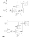
- the illustrated device 1 for influencing a heating controller 2 has as the sensor value simulator 3 a resistance simulator which outputs a simulated resistance value Rs to the heating controller 2.
- the resistance simulator 3 is connected to an interface 4 of the heating controller 2, to which a temperature sensor 5 can basically be connected, which is used in particular to record the outside temperature or the flow temperature of the heating medium and a resistance value R0 depending on the temperature prevailing at the measuring location (outside temperature of the Air or flow temperature of the heating medium).
- the temperature sensor 5 is disconnected from the interface 4 of the heating controller 2 and connected to the device 1.
- a resistance measuring mechanism 6 is provided in the device 1, which determines an actuating variable X (R0) corresponding to this from the analog resistance value R0 and forwards it to a processor 7 of the device 1.
- a correction manipulated variable X (dR) which is generated by a manipulated variable correction module 8, is also processed in the processor 7.
- the manipulated variable correction module 8 can simply be an interface for connecting, for example, an upstream heat adaptation control, which provides a correction value for the flow temperature generated in the heating controller 2 on the basis of the heating characteristic. in the Within the scope of the invention, however, the manipulated variable correction module 8 can also be a complete heat output adaptation control or the like, which automatically determines the corrected manipulated variable X (dR), for example on the basis of measured values within the building.
- an upstream heat adaptation control which provides a correction value for the flow temperature generated in the heating controller 2 on the basis of the heating characteristic.
- the manipulated variable correction module 8 can also be a complete heat output adaptation control or the like, which automatically determines the corrected manipulated variable X (dR), for example on the basis of measured values within the building.
- An output manipulated variable X (Rs) of the corrective value Rs is determined in the processor 7 of the device 1 from the manipulated variables X (R0) of the sensor resistance value and the corrective manipulated variable X (dR), which in the sensor value simulator, for example, converts back into an analog value as a simulated resistance value Rs is translated and output to controller 2.
- the present invention is not limited to the shown division of the individual method steps of the device 1.
- the processor 7 and the sensor value simulator 3 can be combined in one unit, so that a separate output of the output manipulated variable X (Rs) is omitted and the simulated resistance value Rs is output directly to the heating controller 2.
- the processor 7 can be designed as a microprocessor or analog arithmetic unit.
- the resistance value R0 measured by the temperature sensor 5 is output as the simulated resistance value Rs.
- the resistance value Rs generated by the sensor value simulator 3 thus corresponds to the measured sensor resistance value R0.
- the method according to the invention can therefore be carried out, in which, instead of a sensor normally connected to the heating controller, a simulated sensor signal is formed as a correction value, taking into account the measured sensor value, around heating controller 2, not shown To influence the heating system and adjust its heating characteristics.
- FIG. 2 A variant of the device 1 for influencing the heating controller 2 is shown, which has a structure that is essentially comparable to the device 1 described above and is equipped with the same functional elements. These point in Fig. 2 the same reference numerals and are not explained in more detail below.
- a reference sensor 9 is provided in this variant of the invention, which generates a reference sensor resistance value R1. This is converted into a manipulated variable X (R1) of the reference sensor resistance value in a resistive measuring mechanism 6 which operates analogously to the previously described resistance measuring mechanism and is fed to the processor 7 together with the other correcting variables.
- the processor 7 determines the associated temperature value T from the reference sensor resistance values R1 on the basis of the known temperature characteristic, which is set in relation to the sensor resistance value R0 of the temperature sensor 5, the resistance-temperature characteristic curve of which is not known. Over time, the entire R-T characteristic of the temperature sensor can be recorded and saved.
- the resistance simulation in the sensor value simulator 3 can then be controlled accordingly by specifying the correction manipulated variable X (dR) to be set to give the heating controller 2 the corresponding resistance correction value Rs. If the characteristic curve of the temperature sensor 5 is known, the reference sensor 9 can be dispensed with.
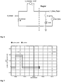
- Temperature-dependent resistance sensors essentially differ in their base resistance (e.g. at 20 ° C ambient temperature), the basic temperature dependency (NTC, PTC) and the curvature of the characteristic.
- NTC basic temperature dependency
- PTC basic temperature dependency
- an algorithm can, for example, increase the sensor current until the voltage value is sufficiently accurate for the measurement.
- the measuring mechanism used for this can, for example, the in Fig. 2 described resistance measuring mechanism 6 of the reference sensor 9.
- the sensor current can be increased from measurement to measurement by discrete steps until the measured voltage at sensor 5, 9 lies outside the upper limit of the voltage measurement range. Then the next smaller measuring sensor current is used for the measurement. If a voltage value outside the upper limit of the voltage range occurs again during further measurements, the sensor current is reduced again by one step. If a voltage value outside the lower limit of the voltage measuring range occurs during further measurements, the sensor current is increased again by one step. If one selects the number and the spacing of the stages in accordance with the family of sensors 5, 9 that is normally expected, then the sensor current generally does not have to be changed as soon as the sensor has recorded at least a sufficiently large and a sufficiently small resistance value. However, it remains possible to compensate for characteristic drifts that occur over time.
- the sensor measuring current is briefly increased in such a way that it heats up slightly and the following measurement value is either larger or smaller depending on the type of characteristic.
- the temperature sensor 5 remains connected directly to the heating controller 2 via the interface 4, the two lines of the circuit for connection to the interface 4 in Fig. 3 In contrast to the 1 and 2 up to the heating controller 2 are shown. In the 1 and 2 these lines to the heating controllers 2 are replaced by arrows in the illustration.
- the resistance simulator 3 designed according to the invention is then parallel to the sensor 5 at the interface 4 of the heating controller 2 in order to apply the simulated resistance value to the heating controller 2 as a correction value Rs.
- the sensor resistance value R0 of the temperature sensor 5 is determined by recording the current and / or voltage profile of the resistance measurement circuit of the heating controller 2 or in the measurement gaps in the case of a keyed resistance measurement circuit using its own resistance measurement mechanism 6, as in FIG Fig. 3 shown, determined.
- a correcting manipulated variable X (dR) is specified by a manipulated variable correction module 8 and together with the manipulated variable X (R0) of the sensor resistance value R0 to one Processor 7 is supplied, which generates an output manipulated variable X (Rs) and forwards it to sensor value simulator 3.
- Fig. 4 shown device 10 for influencing a heating controller 2, similar to the illustration in FIG Fig. 2 , additionally a reference sensor 9 connected to the processor 7.
- the works in Fig. 4 Device 10 shown corresponds to that in Fig. 3 shown device for influencing a heating controller.
- the sensor value simulator 3 is a resistance simulator which alternatively consists of controlled cascaded series and / or parallel connections of resistors, of current and / or voltage sources, of resistance-emitting semiconductor elements such as field-effect transistors and / or of light controlled, light-dependent resistors (LDR) or a combination of the above components.
- the cascaded or parallel-connected resistors can be cascaded, for example, by CMOS switches, relays and / or transistor switches.
- CMOS switches are particularly inexpensive, wear-free and switch quickly.
- relays are only suitable if a few, time-uncritical switching operations are required, such as, for example, the one-time selection of the range of the resistance simulator 3 during commissioning depending on the sensor type.
- switched resistance networks optocouplers with light-dependent resistance output (LDR), optocouplers with field effect transistor (FET) output, and current and voltage sources and / or sinks are provided as a resistance simulation circuit.
- FIG Fig. 5 A device 11 for influencing a heating controller 2 with a bipolar voltage source as a sensor value simulator 12 is shown in FIG Fig. 5 shown.
- the resistance value R0 of the temperature sensor 5 is influenced by means of an impressed voltage or current source / sink.
- This has the advantage that simple circuits, such as a voltage measuring mechanism and a voltage source as an interlocking, can be used for the measurement and correction of the sensor value R0.
- the measurement and correction circuit can remain on the temperature sensor 5 at any time. This can continuously improve the quality of the correction.
- a possible disadvantage is that not every resistance measuring method, in particular no AC-based or integrating measuring method, of the heating controller 2 can be influenced thereby.
- the resistance measuring mechanism 6 is further replaced by a voltage measuring mechanism 13.
- the bipolar voltage source designed as a sensor value simulator 12 replaces the resistance simulator 3. Otherwise, the method can be used analogously, so that functional units are provided with the same reference numerals and a detailed description can be omitted here.
- the voltage across the temperature sensor 5 is measured in the voltage measuring mechanism 13 at the shortest possible intervals so that a dynamic voltage curve of the heating controller 2, as occurs, for example, in the case of pulsed measuring methods, can also be recorded.
- the pulsing of the measuring current is widespread when measuring temperature sensors 5, so that the temperature sensor 5 does not heat up as a result of measurement and there are no measurement errors.
- the interface 4 of the measuring circuit of the heating controller 2 is generally only switched to low resistance during the measurement and the bipolar voltage source 12 is connected in series, the measuring current caused by the voltage source 12 only flows at the measuring time determined by the heating controller 2.
- the voltage source can remain on the circuit continuously and does not need to be switched. In the event that no correction is to be made, the voltage source is set to 0V.
- FIG. 6 A corresponding simulation circuit for voltage correction is in Fig. 6 shown.
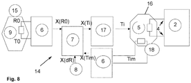
- FIG Fig. 8 A last embodiment of the device 14 according to the invention for influencing a heating controller 2 is shown in FIG Fig. 8 shown.
- the temperature sensor 5 remains connected to the interface 4 of the heating controller 2 in a conventional manner.
- the temperature sensor 5 is removed from its original measuring location 15 and installed in a temperature chamber 16.
- the actual temperature information is instead detected by the reference sensor 9, which is measured by the resistance measuring mechanism 6. This passes on the manipulated variable of the sensor resistance value X (R0) to the processor 7 of the device 14.
- the processor 7 also receives the correcting manipulated variable X (dR) from a manipulated variable correction module 8 and changes the manipulated variable of the sensor resistance value X (R0) in the form of an increase or decrease in the ambient temperature X (Ti), which represents an output manipulated variable.
- a temperature control unit 17 is controlled in order to set the temperature Ti measured by the sensor 5 in the temperature chamber 16 in accordance with the output manipulated variable X (Ti).
- the temperature Ti prevailing inside the chamber is determined by a chamber temperature sensor 18 measured with a corresponding resistance measuring mechanism 6 and fed to the processor 7 of the device 14.
- the advantage of this device 14 is that no electrical intervention in the combination of the temperature sensor 5 and the heating controller 2 is required. So that the temperature control unit 17 can regulate the temperature Ti in the temperature chamber 16, the chamber temperature sensor 18 is required, which determines the measured value of the temperature Tim in the temperature chamber 16 and communicates it to the processor 7.
- the temperature control unit 17 can use a Peltier element, for example, which can be switched continuously from heating to cooling operation without wear due to current reversal.
- a pulse-width-modulated control has the advantage of lower hardware expenditure compared to an analog and continuous measurement control, whereby the processor 7 can generate the temperature Ti in the temperature chamber 16 in accordance with the temperature output control variable X (Ti) generated from the control variables X (R0) and X (dR) .
- a pure heating element in the form of an electrically operated heating mat or a pure cooling element, for example based on evaporative cooling, with a compressor, such as in a refrigerator, can be used as the temperature control unit 17.
- a higher flow temperature than measured at the reference temperature sensor 9 should be specified for the heating controller 2 in order to throttle the heating power.
- a pure heating element is the cheapest solution for the temperature control unit 17 in question. In such a case, cooling can take place slowly by adjusting the temperature to the surroundings. The degree of insulation of the temperature chamber 16, which can be dimensioned accordingly, also has an influence here. The use of a pure cooling element is not useful for the purpose described above.
- a Peltier element has the advantage that the temperature can be both raised and lowered below the temperature outside the temperature chamber 16. In addition, both heating and cooling take place actively and can therefore take place faster than with passive temperature compensation by cooling. The insulation of the temperature chamber can accordingly be chosen so effectively that the energy required to maintain the temperature in the temperature chamber is reduced.
- the outside temperature can assume both higher and lower temperature values than those of the boiler room.
- the heating and / or cooling elements can be controlled continuously with a control variable X (Ti), which can take on analog or discrete value increments, or with pulse width modulation.
- X control variable
- the latter has the advantage that, in the simplest case, electrical switches, for example in the form of relays or transistors, can be used to implement the temperature control unit 17.
- a digital-to-analog converter would be required for control with different value levels.
- Preferred variants of the present invention correspond to the embodiments according to 1 to 4 , in which resistance values of the sensor are measured and output to the heating controller 2 with correction via a resistance network comprising resistors which can be connected in parallel.
- a reference sensor is placed in the same place that determined the temperature value. This separate measurement of the flow temperature by the reference sensor 9 enables the effects of the manipulated variable to be recorded precisely.
- Inexpensive, wear-free and fast CMOS switches can preferably be used as switches in the resistance network.
- heating controller 2 Since practically every heating controller 2 has a flow temperature sensor, a controller replacement can be dispensed with with the help of the present invention, since the existing interfaces 4 can be used to influence the controller characteristics of the heating controller 2.
- the type of the temperature sensors used with the heating controller 2 also need not be known.
- the advantage of the preferred variant is an inexpensive implementation, with a separation between measurement of the sensors and simulation also enabling clean galvanic separation and the measurement method of the measuring mechanism being independent of the measurement method of the heating controller.
Landscapes
- Engineering & Computer Science (AREA)
- Physics & Mathematics (AREA)
- General Engineering & Computer Science (AREA)
- General Physics & Mathematics (AREA)
- Thermal Sciences (AREA)
- Chemical & Material Sciences (AREA)
- Combustion & Propulsion (AREA)
- Mechanical Engineering (AREA)
- Automation & Control Theory (AREA)
- Feedback Control In General (AREA)
- Lining Or Joining Of Plastics Or The Like (AREA)
- Control Of Resistance Heating (AREA)
- Control Of Temperature (AREA)
Priority Applications (1)
| Application Number | Priority Date | Filing Date | Title |
|---|---|---|---|
| PL17157144T PL3199876T3 (pl) | 2006-11-22 | 2007-08-23 | Sposób i urządzenie do oddziaływania na regulator ogrzewania |
Applications Claiming Priority (2)
| Application Number | Priority Date | Filing Date | Title |
|---|---|---|---|
| DE102006054996A DE102006054996A1 (de) | 2006-11-22 | 2006-11-22 | Verfahren und Vorrichtung zur Beeinflussung einer Heizungsregelung |
| EP07016527.9A EP1927812A3 (de) | 2006-11-22 | 2007-08-23 | Verfahren und Vorrichtung zur Beeinflussung einer Heizungsregelung |
Related Parent Applications (1)
| Application Number | Title | Priority Date | Filing Date |
|---|---|---|---|
| EP07016527.9A Division EP1927812A3 (de) | 2006-11-22 | 2007-08-23 | Verfahren und Vorrichtung zur Beeinflussung einer Heizungsregelung |
Publications (2)
| Publication Number | Publication Date |
|---|---|
| EP3199876A1 EP3199876A1 (de) | 2017-08-02 |
| EP3199876B1 true EP3199876B1 (de) | 2020-08-05 |
Family
ID=38777915
Family Applications (2)
| Application Number | Title | Priority Date | Filing Date |
|---|---|---|---|
| EP17157144.1A Active EP3199876B1 (de) | 2006-11-22 | 2007-08-23 | Verfahren und vorrichtung zur beeinflussung einer heizungsregelung |
| EP07016527.9A Withdrawn EP1927812A3 (de) | 2006-11-22 | 2007-08-23 | Verfahren und Vorrichtung zur Beeinflussung einer Heizungsregelung |
Family Applications After (1)
| Application Number | Title | Priority Date | Filing Date |
|---|---|---|---|
| EP07016527.9A Withdrawn EP1927812A3 (de) | 2006-11-22 | 2007-08-23 | Verfahren und Vorrichtung zur Beeinflussung einer Heizungsregelung |
Country Status (3)
| Country | Link |
|---|---|
| EP (2) | EP3199876B1 (pl) |
| DE (1) | DE102006054996A1 (pl) |
| PL (1) | PL3199876T3 (pl) |
Families Citing this family (11)
| Publication number | Priority date | Publication date | Assignee | Title |
|---|---|---|---|---|
| PL2093644T3 (pl) * | 2008-02-23 | 2011-05-31 | Techem Energy Services Gmbh | Sposób i urządzenie do wpływania na pomiar temperatury na wlocie do regulatora ogrzewania |
| DE102009019235A1 (de) | 2009-04-28 | 2010-11-11 | Techem Energy Services Gmbh | Verfahren und Vorrichtung zur Ermittlung eines Korrekturwertes |
| DE102010006110A1 (de) | 2010-01-29 | 2011-08-04 | IAIB e.V., 23966 | Verfahren und Vorrichtung zur Regelung einer Heizung |
| SE534894C2 (sv) * | 2010-06-30 | 2012-02-07 | Ekofektiv Ab | Förfarande och anordning för energistyrning |
| SE536751C2 (sv) * | 2012-10-18 | 2014-07-15 | Ecofective Ab | Förfarande samt anordning för att reglera inomhustemperaturen i en fastighet |
| DE202013008194U1 (de) * | 2013-09-17 | 2014-12-18 | Hkw - Elektronik Gmbh | Geber für eine Heizungsanlage |
| SE539149C2 (sv) * | 2013-12-17 | 2017-04-18 | Xip Tech Ab | Anordning för styrning av klimatutrustning |
| DE102014204367A1 (de) * | 2014-03-10 | 2015-09-10 | Kermi Gmbh | Verfahren und Vorrichtung zur Erhöhung der Speicherkapazität von Wasserspeichern in Anlagen zur Beheizung von Gebäuden und/oder zur Erwärmung von Trink- und/oder Brauchwasser |
| NL2014297B1 (nl) * | 2015-02-13 | 2017-01-13 | Agur B V | Werkwijze en inrichting voor het verwarmen van een gebouw en regeleenheid voor ruimteverwarming |
| DE102022126020A1 (de) * | 2022-10-07 | 2024-04-18 | E.On Se | Kontrollsystem und Heizsystem |
| DE102022126018A1 (de) * | 2022-10-07 | 2024-04-18 | E.On Se | Kontrollverfahren, Kontrollsystem, Computerprogrammprodukt und computerlesbares Medium |
Family Cites Families (13)
| Publication number | Priority date | Publication date | Assignee | Title |
|---|---|---|---|---|
| DE2004233A1 (de) * | 1970-01-30 | 1971-08-12 | Centra Buerkle Kg Albert | Verfahren und Einrichtung zur Beeinflussung der Raumtemperatur |
| DE2840805C2 (de) * | 1978-09-20 | 1980-02-28 | Joh. Vaillant Gmbh U. Co, 5630 Remscheid | Steuereinrichtung für eine Wärmequelle |
| DD147873A1 (de) * | 1979-12-13 | 1981-04-22 | Frank Foerster | Einrichtung zur aussentemperaturmessung und sollwertsimulierung fuer heizungs-temperaturregelanlagen |
| EP0036567B1 (de) * | 1980-03-22 | 1986-05-14 | Joh. Vaillant GmbH u. Co. | Steuereinrichtung für einen Umlaufwasserheizer |
| DE3111989A1 (de) * | 1981-03-26 | 1982-10-14 | KKW Kulmbacher Klimageräte-Werk GmbH, 8650 Kulmbach | Aufladesteuerung fuer elektrische waermespeicher-heizgeraete |
| DE4023439A1 (de) * | 1989-08-12 | 1991-02-14 | Hellmuth Moehlenhoff | Schaltungsanordnung zur regelung der temperatur in einem raum |
| DE4127493C2 (de) * | 1991-08-20 | 2002-02-07 | Norbert Krumm | Thermo-Controller |
| DE4227515A1 (de) * | 1992-08-20 | 1994-02-24 | Metz Lothar Andreas | Witterungsgeführte Heizungssteuerung |
| DE4312800A1 (en) * | 1993-04-20 | 1993-09-23 | Roversy Verteilertechnik Gmbh | Starting up system for surface heating esp. floor heating installation - has at least one heating circuit with desired value transmitter for supply temp., mixer for adjusting supply temp. ,and supply temp. regulator |
| DE19707844A1 (de) * | 1997-02-27 | 1998-09-03 | Walther Dr Menhardt | Schnelles, korrigierendes Thermometer |
| IT1297485B1 (it) * | 1997-12-01 | 1999-12-17 | Paolo Rastelli | Simulatore del funzionamento di rilevatori di grandezze fisiche diverse impiegati per comandare e/o controllare apparecchiature |
| DE19847503A1 (de) * | 1998-10-15 | 2000-04-20 | Ego Elektro Geraetebau Gmbh | Elektrische Schalteinrichtung |
| DE202006001553U1 (de) * | 2006-02-01 | 2006-06-29 | Handwerkskammer Osnabrück-Emsland | Schulungsgerät |
-
2006
- 2006-11-22 DE DE102006054996A patent/DE102006054996A1/de not_active Withdrawn
-
2007
- 2007-08-23 EP EP17157144.1A patent/EP3199876B1/de active Active
- 2007-08-23 PL PL17157144T patent/PL3199876T3/pl unknown
- 2007-08-23 EP EP07016527.9A patent/EP1927812A3/de not_active Withdrawn
Non-Patent Citations (1)
| Title |
|---|
| None * |
Also Published As
| Publication number | Publication date |
|---|---|
| EP1927812A3 (de) | 2014-04-16 |
| EP1927812A2 (de) | 2008-06-04 |
| EP3199876A1 (de) | 2017-08-02 |
| DE102006054996A1 (de) | 2008-06-05 |
| PL3199876T3 (pl) | 2021-03-08 |
Similar Documents
| Publication | Publication Date | Title |
|---|---|---|
| EP3199876B1 (de) | Verfahren und vorrichtung zur beeinflussung einer heizungsregelung | |
| EP2877866B1 (de) | Schaltungsanordnung zur erfassung einer art eines magnetventils | |
| DE102017123881A1 (de) | System und Verfahren zur Temperaturerfassung und -steuerung resistiver Heizelemente | |
| EP2664905A2 (de) | Temperaturmesseinrichtung, elektrisches Gerät mit einer solchen Temperaturmesseinrichtung und Verfahren zur Temperaturmessung | |
| DE102009003206A1 (de) | Vorrichtung zum Detektieren eines Betriebszustands eines Leistungshalbleiterbauelements | |
| DE2139999A1 (de) | Zustandsfuhlerschaltung in Brücken anordnung | |
| EP3111284B1 (de) | Redundierbare eingangsschaltung, eingangsschaltungseinheit mit mindestens einer eingangsschaltung und verfahren zum betrieb einer solchen eingangsschaltungseinheit | |
| DE102007059847A1 (de) | Feldgerät zur Prozessinstrumentierung | |
| EP2805869B1 (de) | Heizeinrichtung für Kraftfahrzeuge, Sitzheizung sowie Lenkradheizung mit einer solchen Heizeinrichtung und Verfahren zur Steuerung der Temperatur einer Heizeinrichtung für Kraftfahrzeuge | |
| DE102014217070A1 (de) | Vorrichtung zur Versorgung mindestens eines Verbrauchers mit elektrischer Energie bzw. zur Bereitstellung elektrischer Leistung für mindestens einen Verbraucher | |
| WO1998024008A1 (de) | Regelkreis aus digitalem regler und regelstrecke zur regelung des eingangsstroms eines elektrischen aktors unter verwendung der pulsweitenmodulation | |
| EP0045737A2 (de) | Temperaturregeleinrichtung für Klima- bzw. Heizanlagen, vorzugsweise in Eisenbahnfahrzeugen | |
| DE102012004526A1 (de) | Verfahren für den Betrieb einer Heizung eines Sitzes eines Kraftfahrzeugs | |
| DE102014219130A1 (de) | Diagnoseschaltung und Verfahren zum Betreiben einer Diagnoseschaltung | |
| DE102010012688A1 (de) | Schaltanordnung mit Temperaturkompensation | |
| DE102013213566A1 (de) | Vorrichtung und Verfahren zur Messung einer Stromstärke | |
| DE102014216609A1 (de) | Überwachung einer Spule | |
| WO2021058302A1 (de) | Verfahren und einrichtung zum ermitteln einer eine temperatur eines widerstandstemperaturfühlers beschreibenden temperaturinformation, wechselrichter, fahrzeug und computerprogramm | |
| WO2021009147A1 (de) | VORRICHTUNG UND VERFAHREN ZUM MESSEN EINES DURCH EINE PWM-ANGESTEUERTE INDUKTIVE LAST FLIEßENDEN STROMES | |
| EP0943077A1 (de) | Verfahren zum betreiben eines widerstandsheizelementes und vorrichtung zum durchführen des verfahrens | |
| DE102016103141A1 (de) | Neupartitionierung eines Chips, der eine SW-Steuerungsarchitektur trägt, für induktive Lasten | |
| EP3211377B1 (de) | Sensor und verfahren zum heizen eines sensors | |
| EP1936454A1 (de) | Steuereinheit zur Steuerung mindestens eines Verbrauchers | |
| EP0060801B1 (de) | Regelvorrichtung für Heizungsanlagen | |
| AT405449B (de) | Verfahren zum steuern einer heizungsanlage und vorrichtung zur durchführung des verfahrens |
Legal Events
| Date | Code | Title | Description |
|---|---|---|---|
| PUAI | Public reference made under article 153(3) epc to a published international application that has entered the european phase |
Free format text: ORIGINAL CODE: 0009012 |
|
| STAA | Information on the status of an ep patent application or granted ep patent |
Free format text: STATUS: THE APPLICATION HAS BEEN PUBLISHED |
|
| AC | Divisional application: reference to earlier application |
Ref document number: 1927812 Country of ref document: EP Kind code of ref document: P |
|
| AK | Designated contracting states |
Kind code of ref document: A1 Designated state(s): AT BE BG CH CY CZ DE DK EE ES FI FR GB GR HU IE IS IT LI LT LU LV MC MT NL PL PT RO SE SI SK TR |
|
| STAA | Information on the status of an ep patent application or granted ep patent |
Free format text: STATUS: REQUEST FOR EXAMINATION WAS MADE |
|
| 17P | Request for examination filed |
Effective date: 20180201 |
|
| RBV | Designated contracting states (corrected) |
Designated state(s): AT BE BG CH CY CZ DE DK EE ES FI FR GB GR HU IE IS IT LI LT LU LV MC MT NL PL PT RO SE SI SK TR |
|
| GRAP | Despatch of communication of intention to grant a patent |
Free format text: ORIGINAL CODE: EPIDOSNIGR1 |
|
| STAA | Information on the status of an ep patent application or granted ep patent |
Free format text: STATUS: GRANT OF PATENT IS INTENDED |
|
| INTG | Intention to grant announced |
Effective date: 20200420 |
|
| GRAS | Grant fee paid |
Free format text: ORIGINAL CODE: EPIDOSNIGR3 |
|
| GRAA | (expected) grant |
Free format text: ORIGINAL CODE: 0009210 |
|
| STAA | Information on the status of an ep patent application or granted ep patent |
Free format text: STATUS: THE PATENT HAS BEEN GRANTED |
|
| AC | Divisional application: reference to earlier application |
Ref document number: 1927812 Country of ref document: EP Kind code of ref document: P |
|
| AK | Designated contracting states |
Kind code of ref document: B1 Designated state(s): AT BE BG CH CY CZ DE DK EE ES FI FR GB GR HU IE IS IT LI LT LU LV MC MT NL PL PT RO SE SI SK TR |
|
| REG | Reference to a national code |
Ref country code: GB Ref legal event code: FG4D Free format text: NOT ENGLISH |
|
| REG | Reference to a national code |
Ref country code: CH Ref legal event code: EP |
|
| REG | Reference to a national code |
Ref country code: AT Ref legal event code: REF Ref document number: 1299245 Country of ref document: AT Kind code of ref document: T Effective date: 20200815 |
|
| REG | Reference to a national code |
Ref country code: DE Ref legal event code: R096 Ref document number: 502007016908 Country of ref document: DE |
|
| REG | Reference to a national code |
Ref country code: IE Ref legal event code: FG4D Free format text: LANGUAGE OF EP DOCUMENT: GERMAN |
|
| REG | Reference to a national code |
Ref country code: LT Ref legal event code: MG4D |
|
| REG | Reference to a national code |
Ref country code: NL Ref legal event code: MP Effective date: 20200805 |
|
| PG25 | Lapsed in a contracting state [announced via postgrant information from national office to epo] |
Ref country code: FI Free format text: LAPSE BECAUSE OF FAILURE TO SUBMIT A TRANSLATION OF THE DESCRIPTION OR TO PAY THE FEE WITHIN THE PRESCRIBED TIME-LIMIT Effective date: 20200805 Ref country code: SE Free format text: LAPSE BECAUSE OF FAILURE TO SUBMIT A TRANSLATION OF THE DESCRIPTION OR TO PAY THE FEE WITHIN THE PRESCRIBED TIME-LIMIT Effective date: 20200805 Ref country code: BG Free format text: LAPSE BECAUSE OF FAILURE TO SUBMIT A TRANSLATION OF THE DESCRIPTION OR TO PAY THE FEE WITHIN THE PRESCRIBED TIME-LIMIT Effective date: 20201105 Ref country code: GR Free format text: LAPSE BECAUSE OF FAILURE TO SUBMIT A TRANSLATION OF THE DESCRIPTION OR TO PAY THE FEE WITHIN THE PRESCRIBED TIME-LIMIT Effective date: 20201106 Ref country code: ES Free format text: LAPSE BECAUSE OF FAILURE TO SUBMIT A TRANSLATION OF THE DESCRIPTION OR TO PAY THE FEE WITHIN THE PRESCRIBED TIME-LIMIT Effective date: 20200805 Ref country code: LT Free format text: LAPSE BECAUSE OF FAILURE TO SUBMIT A TRANSLATION OF THE DESCRIPTION OR TO PAY THE FEE WITHIN THE PRESCRIBED TIME-LIMIT Effective date: 20200805 Ref country code: PT Free format text: LAPSE BECAUSE OF FAILURE TO SUBMIT A TRANSLATION OF THE DESCRIPTION OR TO PAY THE FEE WITHIN THE PRESCRIBED TIME-LIMIT Effective date: 20201207 |
|
| PG25 | Lapsed in a contracting state [announced via postgrant information from national office to epo] |
Ref country code: LV Free format text: LAPSE BECAUSE OF FAILURE TO SUBMIT A TRANSLATION OF THE DESCRIPTION OR TO PAY THE FEE WITHIN THE PRESCRIBED TIME-LIMIT Effective date: 20200805 Ref country code: NL Free format text: LAPSE BECAUSE OF FAILURE TO SUBMIT A TRANSLATION OF THE DESCRIPTION OR TO PAY THE FEE WITHIN THE PRESCRIBED TIME-LIMIT Effective date: 20200805 Ref country code: IS Free format text: LAPSE BECAUSE OF FAILURE TO SUBMIT A TRANSLATION OF THE DESCRIPTION OR TO PAY THE FEE WITHIN THE PRESCRIBED TIME-LIMIT Effective date: 20201205 |
|
| REG | Reference to a national code |
Ref country code: CH Ref legal event code: PL |
|
| PG25 | Lapsed in a contracting state [announced via postgrant information from national office to epo] |
Ref country code: DK Free format text: LAPSE BECAUSE OF FAILURE TO SUBMIT A TRANSLATION OF THE DESCRIPTION OR TO PAY THE FEE WITHIN THE PRESCRIBED TIME-LIMIT Effective date: 20200805 Ref country code: CH Free format text: LAPSE BECAUSE OF NON-PAYMENT OF DUE FEES Effective date: 20200831 Ref country code: CZ Free format text: LAPSE BECAUSE OF FAILURE TO SUBMIT A TRANSLATION OF THE DESCRIPTION OR TO PAY THE FEE WITHIN THE PRESCRIBED TIME-LIMIT Effective date: 20200805 Ref country code: RO Free format text: LAPSE BECAUSE OF FAILURE TO SUBMIT A TRANSLATION OF THE DESCRIPTION OR TO PAY THE FEE WITHIN THE PRESCRIBED TIME-LIMIT Effective date: 20200805 Ref country code: LU Free format text: LAPSE BECAUSE OF NON-PAYMENT OF DUE FEES Effective date: 20200823 Ref country code: LI Free format text: LAPSE BECAUSE OF NON-PAYMENT OF DUE FEES Effective date: 20200831 Ref country code: EE Free format text: LAPSE BECAUSE OF FAILURE TO SUBMIT A TRANSLATION OF THE DESCRIPTION OR TO PAY THE FEE WITHIN THE PRESCRIBED TIME-LIMIT Effective date: 20200805 |
|
| REG | Reference to a national code |
Ref country code: DE Ref legal event code: R097 Ref document number: 502007016908 Country of ref document: DE |
|
| REG | Reference to a national code |
Ref country code: BE Ref legal event code: MM Effective date: 20200831 |
|
| PG25 | Lapsed in a contracting state [announced via postgrant information from national office to epo] |
Ref country code: MC Free format text: LAPSE BECAUSE OF FAILURE TO SUBMIT A TRANSLATION OF THE DESCRIPTION OR TO PAY THE FEE WITHIN THE PRESCRIBED TIME-LIMIT Effective date: 20200805 |
|
| PLBE | No opposition filed within time limit |
Free format text: ORIGINAL CODE: 0009261 |
|
| STAA | Information on the status of an ep patent application or granted ep patent |
Free format text: STATUS: NO OPPOSITION FILED WITHIN TIME LIMIT |
|
| PG25 | Lapsed in a contracting state [announced via postgrant information from national office to epo] |
Ref country code: SK Free format text: LAPSE BECAUSE OF FAILURE TO SUBMIT A TRANSLATION OF THE DESCRIPTION OR TO PAY THE FEE WITHIN THE PRESCRIBED TIME-LIMIT Effective date: 20200805 |
|
| 26N | No opposition filed |
Effective date: 20210507 |
|
| GBPC | Gb: european patent ceased through non-payment of renewal fee |
Effective date: 20201105 |
|
| PG25 | Lapsed in a contracting state [announced via postgrant information from national office to epo] |
Ref country code: FR Free format text: LAPSE BECAUSE OF NON-PAYMENT OF DUE FEES Effective date: 20201005 |
|
| PG25 | Lapsed in a contracting state [announced via postgrant information from national office to epo] |
Ref country code: BE Free format text: LAPSE BECAUSE OF NON-PAYMENT OF DUE FEES Effective date: 20200831 Ref country code: IE Free format text: LAPSE BECAUSE OF NON-PAYMENT OF DUE FEES Effective date: 20200823 Ref country code: SI Free format text: LAPSE BECAUSE OF FAILURE TO SUBMIT A TRANSLATION OF THE DESCRIPTION OR TO PAY THE FEE WITHIN THE PRESCRIBED TIME-LIMIT Effective date: 20200805 |
|
| REG | Reference to a national code |
Ref country code: AT Ref legal event code: MM01 Ref document number: 1299245 Country of ref document: AT Kind code of ref document: T Effective date: 20200823 |
|
| PG25 | Lapsed in a contracting state [announced via postgrant information from national office to epo] |
Ref country code: AT Free format text: LAPSE BECAUSE OF NON-PAYMENT OF DUE FEES Effective date: 20200823 |
|
| PG25 | Lapsed in a contracting state [announced via postgrant information from national office to epo] |
Ref country code: GB Free format text: LAPSE BECAUSE OF NON-PAYMENT OF DUE FEES Effective date: 20201105 |
|
| PG25 | Lapsed in a contracting state [announced via postgrant information from national office to epo] |
Ref country code: IS Free format text: LAPSE BECAUSE OF FAILURE TO SUBMIT A TRANSLATION OF THE DESCRIPTION OR TO PAY THE FEE WITHIN THE PRESCRIBED TIME-LIMIT Effective date: 20201205 Ref country code: TR Free format text: LAPSE BECAUSE OF FAILURE TO SUBMIT A TRANSLATION OF THE DESCRIPTION OR TO PAY THE FEE WITHIN THE PRESCRIBED TIME-LIMIT Effective date: 20200805 Ref country code: MT Free format text: LAPSE BECAUSE OF FAILURE TO SUBMIT A TRANSLATION OF THE DESCRIPTION OR TO PAY THE FEE WITHIN THE PRESCRIBED TIME-LIMIT Effective date: 20200805 Ref country code: CY Free format text: LAPSE BECAUSE OF FAILURE TO SUBMIT A TRANSLATION OF THE DESCRIPTION OR TO PAY THE FEE WITHIN THE PRESCRIBED TIME-LIMIT Effective date: 20200805 |
|
| PGFP | Annual fee paid to national office [announced via postgrant information from national office to epo] |
Ref country code: DE Payment date: 20240926 Year of fee payment: 18 |
|
| PGFP | Annual fee paid to national office [announced via postgrant information from national office to epo] |
Ref country code: IT Payment date: 20240926 Year of fee payment: 18 |
|
| PGFP | Annual fee paid to national office [announced via postgrant information from national office to epo] |
Ref country code: PL Payment date: 20241021 Year of fee payment: 18 |
|
| REG | Reference to a national code |
Ref country code: DE Ref legal event code: R119 Ref document number: 502007016908 Country of ref document: DE |