EP3199486B1 - Crane mechanism and work platform with a load measuring device and an integrated inclination sensor - Google Patents
Crane mechanism and work platform with a load measuring device and an integrated inclination sensor Download PDFInfo
- Publication number
- EP3199486B1 EP3199486B1 EP16153100.9A EP16153100A EP3199486B1 EP 3199486 B1 EP3199486 B1 EP 3199486B1 EP 16153100 A EP16153100 A EP 16153100A EP 3199486 B1 EP3199486 B1 EP 3199486B1
- Authority
- EP
- European Patent Office
- Prior art keywords
- work platform
- sensor
- crane mechanism
- boom
- detection apparatus
- Prior art date
- Legal status (The legal status is an assumption and is not a legal conclusion. Google has not performed a legal analysis and makes no representation as to the accuracy of the status listed.)
- Active
Links
- 230000007246 mechanism Effects 0.000 title claims description 41
- 238000001514 detection method Methods 0.000 claims description 30
- 238000011156 evaluation Methods 0.000 claims description 22
- 230000001133 acceleration Effects 0.000 claims description 16
- 230000008859 change Effects 0.000 claims description 9
- 230000005484 gravity Effects 0.000 claims description 5
- 238000000034 method Methods 0.000 claims description 3
- 230000008569 process Effects 0.000 claims description 2
- 238000005452 bending Methods 0.000 description 7
- 238000005303 weighing Methods 0.000 description 6
- 230000008901 benefit Effects 0.000 description 3
- 238000010586 diagram Methods 0.000 description 2
- 238000004519 manufacturing process Methods 0.000 description 2
- 239000000463 material Substances 0.000 description 2
- 238000005259 measurement Methods 0.000 description 2
- 238000012544 monitoring process Methods 0.000 description 2
- 230000004044 response Effects 0.000 description 2
- 238000013459 approach Methods 0.000 description 1
- 230000001419 dependent effect Effects 0.000 description 1
- 238000011161 development Methods 0.000 description 1
- 230000018109 developmental process Effects 0.000 description 1
- 230000000694 effects Effects 0.000 description 1
- 239000007788 liquid Substances 0.000 description 1
- 238000012986 modification Methods 0.000 description 1
- 230000004048 modification Effects 0.000 description 1
- 238000003825 pressing Methods 0.000 description 1
- 229910000679 solder Inorganic materials 0.000 description 1
Images


Classifications
-
- B—PERFORMING OPERATIONS; TRANSPORTING
- B66—HOISTING; LIFTING; HAULING
- B66F—HOISTING, LIFTING, HAULING OR PUSHING, NOT OTHERWISE PROVIDED FOR, e.g. DEVICES WHICH APPLY A LIFTING OR PUSHING FORCE DIRECTLY TO THE SURFACE OF A LOAD
- B66F17/00—Safety devices, e.g. for limiting or indicating lifting force
- B66F17/006—Safety devices, e.g. for limiting or indicating lifting force for working platforms
-
- B—PERFORMING OPERATIONS; TRANSPORTING
- B66—HOISTING; LIFTING; HAULING
- B66F—HOISTING, LIFTING, HAULING OR PUSHING, NOT OTHERWISE PROVIDED FOR, e.g. DEVICES WHICH APPLY A LIFTING OR PUSHING FORCE DIRECTLY TO THE SURFACE OF A LOAD
- B66F11/00—Lifting devices specially adapted for particular uses not otherwise provided for
- B66F11/04—Lifting devices specially adapted for particular uses not otherwise provided for for movable platforms or cabins, e.g. on vehicles, permitting workmen to place themselves in any desired position for carrying out required operations
- B66F11/044—Working platforms suspended from booms
- B66F11/046—Working platforms suspended from booms of the telescoping type
-
- G—PHYSICS
- G01—MEASURING; TESTING
- G01C—MEASURING DISTANCES, LEVELS OR BEARINGS; SURVEYING; NAVIGATION; GYROSCOPIC INSTRUMENTS; PHOTOGRAMMETRY OR VIDEOGRAMMETRY
- G01C25/00—Manufacturing, calibrating, cleaning, or repairing instruments or devices referred to in the other groups of this subclass
-
- G—PHYSICS
- G01—MEASURING; TESTING
- G01C—MEASURING DISTANCES, LEVELS OR BEARINGS; SURVEYING; NAVIGATION; GYROSCOPIC INSTRUMENTS; PHOTOGRAMMETRY OR VIDEOGRAMMETRY
- G01C9/00—Measuring inclination, e.g. by clinometers, by levels
- G01C9/02—Details
-
- G—PHYSICS
- G01—MEASURING; TESTING
- G01L—MEASURING FORCE, STRESS, TORQUE, WORK, MECHANICAL POWER, MECHANICAL EFFICIENCY, OR FLUID PRESSURE
- G01L5/00—Apparatus for, or methods of, measuring force, work, mechanical power, or torque, specially adapted for specific purposes
- G01L5/0061—Force sensors associated with industrial machines or actuators
- G01L5/0066—Calibration arrangements
Definitions
- Embodiments of the present invention relate to a crane mechanism and a work platform with load detection device and integrated tilt sensor.
- the invention is in the field of aerial work platforms, e.g. Hydraulic aerial work platforms, which are attached via a crane and a truck and must be equipped with a so-called load detection device as a rule.
- load detection devices according to the European patent application are known EP 1 382 562 A1 which are arranged between the crane mechanism and the work platform.
- the publication EP 1 382 562 A1 discloses what follows: a crane mechanism and work platform having a load sensing device, comprising: a crane mechanism for moving the work platform, the crane mechanism attachable to a base, and including a tiltable boom; and a load cell disposed as a single connection between the tiltable boom and the work platform, the load cell having a force sensor configured to detect a force, a side moment, and / or a torsional moment between the crane mechanism and the work platform.
- EP 1 378 482 A1 as well as the EP 1 466 862 A1 in each case an aerial work platform with a telescopic boom and a working basket arranged at one end of the telescopic boom.
- mechanisms are presented that allow the work basket to be moved substantially parallel to the floor.
- the safety shutdown on the basis of the load detection and the tilt regulation are separate systems, each of which has usually provided at least one sensor in the work basket, so that for each system its own wiring along the boom or the telescopic boom is necessary. This primarily increases the assembly effort in the manufacture of aerial work platforms. Furthermore, thick cable harnesses are also a hindrance during operation. Therefore, there is a need for an improved approach.
- the object of the present invention is to better integrate the electrical protection, monitoring and / or control devices.
- Embodiments of the present invention provide a crane platform with a load sensing device.
- the crane mechanism for moving the work platform is attachable to a base and includes a tiltable boom.
- the load detection device comprises a load cell.
- the load cell is disposed between a crane mechanism for moving the work platform and the work platform itself, so that the crane mechanism can move and tilt the work platform vertically and / or horizontally.
- the load cell is arranged as the only connection between the tilting boom and the working platform.
- the load cell has a force sensor and a tilt sensor.
- the force sensor is configured to detect a force, a side moment and / or a torsional moment between the crane mechanism and the work platform.
- the inclination sensor is designed to incline the working platform, e.g. relative to the crane mechanism or as an absolute reference to the ground, i. in terms of gravity, to determine.
- the force sensor and the inclination sensor have a common housing.
- the finding of the present invention is therefore that it has been recognized that the load cell typically present with the force sensor is always arranged between the crane mechanism and working platform, but in particular fixedly opposite the working platform, so that the inclination sensor can also be integrated in the latter, since the inclination sensor can be integrated into the load sensor Load cell with respect to the inclination always behaves the same with the working platform.
- the two sensor elements important synergy effects and thus cost savings can be achieved.
- Alone the provision of the two sensors in a common housing reduces the assembly effort.
- the housing forms either the load cell itself, but it is also conceivable that the two sensor elements are arranged in a separate housing within the load cell. Further advantages arise with regard to the detection of external faults, as will be explained below.
- the load detection device comprises one or more strain gauges for force measurement. These strain gauges are designed to determine a tension in the applied material and, based thereon, to be a value for the load between the crane mechanism or to be close to the boom and to determine the work basket. According to embodiments, a plurality of strain gauges are provided, so that a redundant monitoring is possible.
- the boom may for example be a telescopic boom or a fixed boom, on which the tilting boom is mounted for tilting the platform.
- This tilting boom can be operated for example with a leveling cylinder.
- typically the tiltable boom is aligned so that the work platform is substantially parallel to the ground or substantially perpendicular to the earth's gravity.
- the inclination sensor may be comparable to a spirit level and has an absolute inclination to gravity, e.g. by means of a capacitively monitored pendulum.
- the inclination sensor may also be designed as an angle sensor which determines the tilt between the telescopic boom / fixed boom and the tilting boom.
- both the force sensor and the inclination sensor are driven by a common signal line and / or even a common power supply.
- the force sensor can be designed redundant. According to embodiments, it is also possible to perform the tilt sensor redundant. According to preferred embodiments, only one power supply (power supply) and one microcontroller for the evaluation of the sensor measured values can be provided within the load detection device per "channel". On the one hand, all of these measures have advantages in terms of reducing the wiring effort (i.e., the assembly effort) on the machine. Not only the effort itself, but also the wiring is simplified, which reduces the overall complexity.
- the load cell may be connected to an evaluation unit, which is part of the load detection device. It should be noted at this point that the evaluation unit does not necessarily have to be arranged in the weighing cell. By virtue of the fact that both the one or more force sensors or the one or more inclination sensors with evaluation electronics which are in one and the same Evaluation unit is housed, are evaluated, it is also possible to calibrate all these sensors at the same time. Therefore, according to further embodiments, the evaluation unit may be designed to carry out a common calibration method, eg for calibrating the temperature behavior for all sensors. This saves both personnel and equipment during production and operation.
- the inclination sensor can also be designed as an acceleration sensor.
- the evaluation unit may be designed in such a way, in the case of a load change detected by the force sensor and an acceleration detected simultaneously by the acceleration sensor, to detect an external fault and, starting from this, to put the sensors in a kind of latency state and their signal for a certain period of time (0, 5s or 1s).
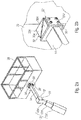
- FIG. 10 shows a crane mechanism 10 with a work cage 20 and a load cell 30 arranged between the crane mechanism 10 and the work cage 20, which constitutes load detection means 1.
- the crane mechanism 10 may be attached to a base 5, eg a mobile trailer or semitrailer, (tiltable or rotatable).
- the crane mechanism 10 in this embodiment comprises a (fixed) boom 12, which is connected to a tiltable boom 14 via a hinge 16.
- the hinge 16 allows tilting of the tiltable boom 14 and thus also of the basket 20 and the load cell 30 relative to the boom 12 about the rotation axis 16a. In other words, it means that when the basket 20 is tilted, the load cell 30 also experiences a corresponding tilting.
- the load cell 30 is disposed between the basket 20 and the tiltable boom 14 and thus configured to determine bending moments or shear forces or compressive forces between the boom 14 and the work basket 20. Subsequently, both the force sensor 32 and the tilt sensor 34 will be explained with reference to the magnification view of the load cell 30.
- the force sensor 32 is based, for example, on the determination of a deformation of the load cell 30 or the housing or other deformation device of the load cell 30.
- the deformation is via a strain gauge (resistive force transducer) or another force transducer, such as. a piezoelectric force transducer determined and used as a measure of the load, since the deformation is in (direct) dependence on the load on the work basket 20 load.
- the deformation is thus dependent on the loading of the basket 20, wherein the material parameters of the deformation body must be taken into account. Therefore, this dependence between the load and the deformation of the deformation body is determined in advance in a calibration process of the load cell or the deformation body.
- deformation bodies depending on how the load cell is arranged (laterally or below) relative to the work basket, there are different deformation bodies, since it depends on whether it is a torsion or compressive force.
- deformation bodies are S-shaped spring bodies, bending beams or ring torsion springs, as further in Fig. 2 will be explained.
- the inclination sensor 34 is also integrated in the load cell 30.
- the inclination sensor 34 can be arranged, for example, with respect to the horizontal and / or the vertical of the weighing cell 30 or of the working basket 20. Since the load detecting means 30 and the load cell 30 are fixedly connected to the basket 20, the inclination sensor of the load detecting means measures the same inclination angle as that of a separate inclination sensor. This inclination sensor 34 thus detects the inclination of the load cell 30 and thus also the inclination of the working basket 20, so that it can be compensated for example by means of the crane mechanism.
- the tilt sensor 34 may comprise a body modeled on a solder that is electronically, inductively, capacitively, or optically monitored so as to determine its location with respect to gravity.
- liquid-based systems that is to say a spirit level, are also known.
- the senor 32-34 of the load cell 30 is connected to a common line 38, via which the two sensors 32 and 34 are supplied together with energy (see reference numeral 38E).
- a signal line 38S may also be provided in the signal body 38, via which signals detected by means of the sensors 32-34 are provided to further devices, such as e.g. be provided to the control device of the aerial work platform.
- Fig. 2a to 2c illustrate the lateral arrangement of a load cell 30 'with respect to the work basket 20.
- the load cell 30' includes both the force sensor (here, for example, a bending bump sensor) and the tilt sensor (here, for example, a Lotsensor).
- the load cell 30 ' comprises a first flange 32' for the work basket and a second flange 34 'for the movable boom 14.
- the two flanges 34' and 32 ' are designed by means of so-called angle plates, so that the screw can be made laterally (see reference numeral 34s 'and 32s').
- Each flange 32 'and 34' is thus connected laterally via the screw 32s 'or 34s' with a half 30a 'and 30b' of the load cell.
- the two halves 30a 'and 30b' are connected to each other via a deformation element (not shown), in which the actual force sensors (DMS) are arranged.
- a deformation element not shown
- the actual force sensors DMS
- a bending of the load cell 30 ' results in the area between the two halves 30a' and 30b '.
- the bending moment M can be determined by means of the force sensor, from which in turn (either arithmetically or on the basis of empirical values) the force F can be deduced.
- the one in here Fig. 2c shown horizontal basket can be about the pivot 16 ', or to be more accurate, about the axis of rotation 16R' tilted.
- the tilting jib 14 is tilted relative to the jib 12 ', which in this embodiment is in the form of a telescopic jib (cf., telescopic elements 12a', 12b 'and 12c').
- This tilt is by means of the tilt sensor, the reference to Fig. 1 has been explained, so that, for example, with a hydraulic leveling cylinder, in the region of the joint 16 'is arranged, the inclination can be compensated.
- This control of the inclination based on the sensor signals is, however, a control that is connected to the evaluation of the load detection device. It should be noted at this point that both the controller and the load evaluation device are preferably not arranged on the boom or the work basket, but on the (vehicle) base of the work platform.
- Fig. 2d shows a work basket 20 ", which is connected via a below the work basket 20" provided load cell 30 "with the boom 14". The connection is made via the two flanges 32 "on the side of the work cage 20" and 34 "on the side of the boom 14".
- the load detection device comprises, as already indicated above, an evaluation unit connected to the load cell and in particular to the two sensors 32 and 34 (cf. Fig. 1 ) of the load cell 30 is connected.
- the evaluation unit can be designed to detect the two sensors simultaneously.
- the evaluation unit can also be arranged in the same housing, in which the two sensor elements force sensor and tilt sensor are arranged.
- the weighing cell itself forms the housing, not only the two sensor elements but also the evaluation unit can be arranged inside the weighing cell.
- the evaluation unit can also be arranged within this housing.
- At least the force sensor or the tilt sensor but preferably both sensors are designed to be redundant.
- a bending moment or a compressive force is determined by means of the force sensor in order to determine the load on the work basket
- other forces such as e.g. a lateral moment or a torsion moment are meaningful in relation to a load on the work basket, if arranged between the boom and the work basket accordingly.
- strain gauges as force sensors
- other measuring principles could be used.
- An example of this is the so-called vibrating string measuring principle.
- a vibrating string load meter it is possible to measure quantities that can be transferred to the tension of a string (for example, a string tensioned in the measuring cell to determine a load on the measuring cell).
- the string is excited to vibrate in the measuring cell, whereby the string detunes due to a load by the force to be measured, so that starting from the changed natural frequency of the string, the load can be determined on the same.
- a relative tilt sensor which with coupled to the joint 16 and determines the tilt angle between the boom 12 and the tiltable boom 14.
- a tilt sensor is an acceleration sensor which is designed primarily to detect an acceleration acting on the sensor element (s) as a change in inclination, but can additionally detect an acceleration in at least one spatial direction.
- a change in weight is detected even if the stage is moved during operation, for example, drives over a curb.
- the telescopic boom then starts to oscillate, indicating a weight change of the basket, although the weight of the basket has remained the same.
- the inclinometer disposed on the telescopic arm will in such a case only indicate a minimum or no change in inclination, since the measured inclination value is output in an acceleration-compensated manner, ie. H. an acceleration acting on the tilt sensor is filtered out.
- Fig. 3 shows a schematic block diagram of the load cell 30 with integrated tilt sensor 34.
- Reference numeral 34a in this case one or more sensor elements for inclination and acceleration measurement.
- two 90 ° offset MEMS sensors are used here, which, however, measure an inclination in only one axis.
- the raw measured value is therefore the signal that has not yet been accelerated.
- a compensation takes place only by the downstream filter 34b.
- the raw measured value is supplied via the signal line 34S to the force sensor 32, which can then derive from this signal whether an acceleration acts on the weighing cell 30 (for example by driving over a curb, etc.) or whether it is an actual weight change of the basket.
- the acceleration-compensated slope value is sent to the evaluation unit 50 via the common signal line 38S.
Landscapes
- Engineering & Computer Science (AREA)
- Structural Engineering (AREA)
- Life Sciences & Earth Sciences (AREA)
- Geology (AREA)
- Mechanical Engineering (AREA)
- Physics & Mathematics (AREA)
- General Physics & Mathematics (AREA)
- Radar, Positioning & Navigation (AREA)
- Remote Sensing (AREA)
- Manufacturing & Machinery (AREA)
- Chemical & Material Sciences (AREA)
- Analytical Chemistry (AREA)
- Forklifts And Lifting Vehicles (AREA)
- Jib Cranes (AREA)
Description
Ausführungsbeispiele der vorliegenden Erfindung beziehen sich auf einen Kranmechanismus und eine Arbeitsbühne mit Lasterfassungseinrichtung und integriertem Neigungssensor. Im Allgemeinen liegt die Erfindung auf dem Gebiet von Hubarbeitsbühnen, z.B. hydraulische Hubarbeitsbühnen, die über einen Kran und einen LKW befestigt sind und im Regelfall mit einer sogenannten Lasterfassungseinrichtung ausgestattet sein müssen.Embodiments of the present invention relate to a crane mechanism and a work platform with load detection device and integrated tilt sensor. In general, the invention is in the field of aerial work platforms, e.g. Hydraulic aerial work platforms, which are attached via a crane and a truck and must be equipped with a so-called load detection device as a rule.
Bekannt sind beispielsweise Lasterfassungseinrichtungen gemäß der europäischen Patentanmeldung
Weiterhin offenbaren die Patentanmeldungen
Die Sicherheitsabschaltung auf Basis der Lasterfassung sowie die Neigungsregulierung sind voneinander getrennte Systeme, die jeweils im Regelfall zumindest einen Sensor im Arbeitskorb vorgesehen haben, so dass für jedes System eine eigene Verkabelung entlang des Auslegers bzw. des Teleskopauslegers notwendig ist. Dies erhöht in erster Linie den Montageaufwand bei der Herstellung von Hubarbeitsbühnen. Des Weiteren sind auch im Betrieb dicke Kabelstränge hinderlich. Deshalb besteht der Bedarf nach einem verbesserten Ansatz.The safety shutdown on the basis of the load detection and the tilt regulation are separate systems, each of which has usually provided at least one sensor in the work basket, so that for each system its own wiring along the boom or the telescopic boom is necessary. This primarily increases the assembly effort in the manufacture of aerial work platforms. Furthermore, thick cable harnesses are also a hindrance during operation. Therefore, there is a need for an improved approach.
Aufgabe der vorliegenden Erfindung ist es, die elektrischen Schutz-, Überwachungs- und/oder Steuerungseinrichtungen besser zu integrieren.The object of the present invention is to better integrate the electrical protection, monitoring and / or control devices.
Die Aufgabe wird durch die unabhängigen Patentansprüche gelöst.The object is solved by the independent claims.
Ausführungsbeispiele der vorliegenden Erfindung schaffen einen Kranmechanismus bzw. eine Arbeitsbühne mit einer Belastungserfassungsvorrichtung. Der Kranmechanismus zum Bewegen der Arbeitsbühne ist an einer Basis befestigbar und umfasst einen verkippbaren Ausleger. Die Belastungserfassungsvorrichtung umfasst eine Wägezelle. Die Wägezelle ist zwischen einem Kranmechanismus zum Bewegen der Arbeitsbühne und der Arbeitsbühne selbst angeordnet, so dass der Kranmechanismus die Arbeitsbühne vertikal und/oder horizontal bewegen sowie verkippen kann. Die Wägezelle ist als einzige Verbindung zwischen dem verkippbaren Ausleger und der Arbeitsbühne angeordnet. Die Wägezelle weist einen Kraftsensor und einen Neigungssensor auf. Der Kraftsensor ist ausgebildet, um eine Kraft, einen Seitenmoment und/oder einen Torsionsmoment zwischen dem Kranmechanismus und der Arbeitsbühne zu erfassen. Der Neigungssensor ist ausgebildet, eine Neigung der Arbeitsbühne, z.B. gegenüber dem Kranmechanismus oder als absolute Referenz gegenüber dem Erdboden, d.h. in Bezug auf die Erdanziehungskraft, zu ermitteln. Der Kraftsensor und der Neigungssensor weisen dabei ein gemeinsames Gehäuse auf.Embodiments of the present invention provide a crane platform with a load sensing device. The crane mechanism for moving the work platform is attachable to a base and includes a tiltable boom. The load detection device comprises a load cell. The load cell is disposed between a crane mechanism for moving the work platform and the work platform itself, so that the crane mechanism can move and tilt the work platform vertically and / or horizontally. The load cell is arranged as the only connection between the tilting boom and the working platform. The load cell has a force sensor and a tilt sensor. The force sensor is configured to detect a force, a side moment and / or a torsional moment between the crane mechanism and the work platform. The inclination sensor is designed to incline the working platform, e.g. relative to the crane mechanism or as an absolute reference to the ground, i. in terms of gravity, to determine. The force sensor and the inclination sensor have a common housing.
Die Erkenntnis der vorliegenden Erfindung liegt also darin, dass erkannt wurde, dass die typischerweise vorhandene Wägezelle mit dem Kraftsensor immer zwischen Kranmechanismus und Arbeitsbühne, aber insbesondere fix gegenüber der Arbeitsbühne angeordnet ist, so dass in diese auch der Neigungssensor integriert werden kann, da sich die Wägezelle in Bezug auf die Neigung immer gleich mit der Arbeitsbühne verhält. Durch die Kombination dieser zwei Sensorikelemente können wichtige Synergieeffekte und dadurch Kostenersparnis erreicht werden. Schon alleine das Vorsehen der zwei Sensoren in einem gemeinsamen Gehäuse reduziert den Montageaufwand. Das Gehäuse bildet dabei entweder die Wägezelle selbst, denkbar ist jedoch auch, dass die beiden Sensorikelemente in einem separaten Gehäuse innerhalb der Wägezelle angeordnet sind. Weitere Vorteile ergeben sich in Hinblick auf die Detektion externer Fehler, wie nachfolgend noch erläutert werden wird.The finding of the present invention is therefore that it has been recognized that the load cell typically present with the force sensor is always arranged between the crane mechanism and working platform, but in particular fixedly opposite the working platform, so that the inclination sensor can also be integrated in the latter, since the inclination sensor can be integrated into the load sensor Load cell with respect to the inclination always behaves the same with the working platform. By combining these two sensor elements important synergy effects and thus cost savings can be achieved. Alone the provision of the two sensors in a common housing reduces the assembly effort. The housing forms either the load cell itself, but it is also conceivable that the two sensor elements are arranged in a separate housing within the load cell. Further advantages arise with regard to the detection of external faults, as will be explained below.
Entsprechend den Ausführungsbeispielen umfasst die Belastungserfassungsvorrichtung einen oder mehrere Dehnungsmessstreifen zur Kraftmessung. Diese Dehnungsmessstreifen sind ausgebildet, um eine Spannung im aufgebrachten Material zu bestimmen und ausgehend hiervon ein Wert für die Belastung zwischen dem Kranmechanismus bzw. um dem Ausleger nahe zu sein und den Arbeitskorb zu bestimmen. Entsprechend Ausführungsbeispielen sind mehrere Dehnungsmessstreifen vorgesehen, so dass eine redundante Überwachung möglich ist.According to the embodiments, the load detection device comprises one or more strain gauges for force measurement. These strain gauges are designed to determine a tension in the applied material and, based thereon, to be a value for the load between the crane mechanism or to be close to the boom and to determine the work basket. According to embodiments, a plurality of strain gauges are provided, so that a redundant monitoring is possible.
Der Ausleger kann beispielsweise ein Teleskopausleger oder ein Festausleger sein, an welchem der verkippbare Ausleger zum Neigen der Arbeitsbühne angebracht ist. Dieser verkippbare Ausleger kann beispielsweise mit einem Nivellierzylinder betätigt werden. In Abhängigkeit von dem Neigungssensorsignal wird typischerweise der verkippbare Ausleger ausgerichtet, so dass die Arbeitsbühne im Wesentlichen parallel zum Boden bzw. sich im Wesentlichen senkrecht zu der Erdanziehung verhält.The boom may for example be a telescopic boom or a fixed boom, on which the tilting boom is mounted for tilting the platform. This tilting boom can be operated for example with a leveling cylinder. In response to the tilt sensor signal, typically the tiltable boom is aligned so that the work platform is substantially parallel to the ground or substantially perpendicular to the earth's gravity.
Für die Ausführung des Neigungssensors gibt es unterschiedliche Varianten. Entsprechend dem ersten Ausführungsbeispiel kann der Neigungssensor vergleichbar mit einer Wasserwaage sein und eine Absolut-Neigung gegenüber der Erdanziehung, z.B. mittels eines kapazitiv überwachten Pendels, ermitteln. Alternativ hierzu kann entsprechend weiteren Ausführungsbeispielen der Neigungssensor auch als Winkelsensor ausgeführt sein, der die Verkippung zwischen dem Teleskopausleger/festen Ausleger und dem verkippbaren Ausleger bestimmt.For the execution of the tilt sensor, there are different variants. According to the first embodiment, the inclination sensor may be comparable to a spirit level and has an absolute inclination to gravity, e.g. by means of a capacitively monitored pendulum. Alternatively, according to further embodiments of the inclination sensor may also be designed as an angle sensor which determines the tilt between the telescopic boom / fixed boom and the tilting boom.
Entsprechend bevorzugten Ausführungsbeispielen wird, insbesondere um den Verkabelungsaufwand zu reduzieren, sowohl der Kraftsensor als auch der Neigungssensor mit einer gemeinsamen Signalleitung und/oder sogar einer gemeinsamen Energieversorgung angesteuert.According to preferred embodiments, in particular in order to reduce the wiring complexity, both the force sensor and the inclination sensor are driven by a common signal line and / or even a common power supply.
Wie oben bereits erläutert, kann entsprechend Ausführungsbeispielen der Kraftsensor redundant ausgeführt sein. Entsprechend Ausführungsbeispielen ist es ebenso möglich, den Neigungssensor redundant auszuführen. Entsprechend bevorzugten Ausführungsbeispielen kann so innerhalb der Lasterfassungseinrichtung pro "Kanal" nur noch eine Stromversorgung (Netzteil) sowie ein Mikrocontroller für die Auswertung der Sensormesswerte vorgesehen sein. All diese Maßnahmen haben einerseits Vorteile im Hinblick auf eine Reduzierung des Verkabelungsaufwands (d.h. des Montageaufwands) an der Maschine. Nicht nur der Aufwand an sich, sondern auch die Verkabelung wird vereinfacht, was die gesamte Komplexität reduziert.As already explained above, according to embodiments of the force sensor can be designed redundant. According to embodiments, it is also possible to perform the tilt sensor redundant. According to preferred embodiments, only one power supply (power supply) and one microcontroller for the evaluation of the sensor measured values can be provided within the load detection device per "channel". On the one hand, all of these measures have advantages in terms of reducing the wiring effort (i.e., the assembly effort) on the machine. Not only the effort itself, but also the wiring is simplified, which reduces the overall complexity.
Entsprechend weiteren Ausführungsbeispielen kann die Wägezelle mit einer Auswerteeinheit verbunden sein, die Teil der Belastungserfassungsvorrichtung ist. An dieser Stelle sei angemerkt, dass die Auswerteeinheit nicht zwingend in der Wägezelle angeordnet sein muss. Dadurch, dass sowohl der eine oder die mehreren Kraftsensoren oder der eine oder mehrere Neigungssensoren mit einer Auswerteelektronik, die in der ein und derselben Auswerteeinheit beherbergt ist, ausgewertet werden, ist es auch möglich, all diese Sensoren gleichzeitig zu kalibrieren. Deshalb kann entsprechend weiteren Ausführungsbeispielen die Auswerteeinheit dazu ausgebildet sein, ein gemeinsames Kalibrierverfahren, z.B. zur Kalibrierung des Temperaturverhaltens für alle Sensoren durchzuführen. Dies spart sowohl bei der Herstellung als auch im Betrieb Kosten für Personal und Gerät.According to further embodiments, the load cell may be connected to an evaluation unit, which is part of the load detection device. It should be noted at this point that the evaluation unit does not necessarily have to be arranged in the weighing cell. By virtue of the fact that both the one or more force sensors or the one or more inclination sensors with evaluation electronics which are in one and the same Evaluation unit is housed, are evaluated, it is also possible to calibrate all these sensors at the same time. Therefore, according to further embodiments, the evaluation unit may be designed to carry out a common calibration method, eg for calibrating the temperature behavior for all sensors. This saves both personnel and equipment during production and operation.
Entsprechend zusätzlichen Ausführungsbeispielen kann der Neigungssensor auch als Beschleunigungssensor ausgeführt sein. Hieraus ergibt sich der Vorteil, dass auch eine Beschleunigung der Arbeitsbühne erfasst werden kann, um hieraus auf einen externen Fehler (bspw. ein Überfahren eines Borsteines mit hieraus resultierendem Auf- und Abschwingen bzw. Hin- und Herbewegen des Kranmechanismus und der Arbeitsbühne) zu schließen. Deshalb kann die Auswerteeinheit derart ausgebildet sein, bei einer mittels des Kraftsensors erfassten Laständerung und einer gleichzeitig mittels des Beschleunigungssensors erfassten Beschleunigung, einen externen Fehler zu erkennen und ausgehend hiervon die Sensoren in eine Art Latenzzustand zu versetzen und deren Signal für eine gewisse Zeitspanne (0,5s oder 1s) zu ignorieren.According to additional embodiments, the inclination sensor can also be designed as an acceleration sensor. This results in the advantage that an acceleration of the platform can be detected in order to conclude from this on an external error (for example, a driving over a Borsteines with resulting swinging up and down or reciprocating the crane mechanism and the work platform) , Therefore, the evaluation unit may be designed in such a way, in the case of a load change detected by the force sensor and an acceleration detected simultaneously by the acceleration sensor, to detect an external fault and, starting from this, to put the sensors in a kind of latency state and their signal for a certain period of time (0, 5s or 1s).
Weiterbildungen sind in den Unteransprüchen definiert. Ausführungsbeispiele der vorliegenden Erfindung werden anhand der beiliegenden Zeichnungen erläutert. Es zeigen:
- Fig. 1
- ein schematisches Blockschaltbild einer Belastungserfassungsvorrichtung für einen Kranmechanismus bzw. eine Arbeitsbühne gemäß Ausführungsbeispielen;
- Fig. 2a-2d
- schematische dreidimensionale Abbildungen von einem Kranmechanismus, einer Arbeitsbühne und einer dazwischen angeordneten Wägezelle, die den Kraftsensor und den Neigungssensor umfasst, gemäß Ausführungsbeispielen; und
- Fig. 3
- schematische Abbildung einer Belastungserfassungsvorrichtung gemäß erweiterten Ausführungsbeispielen.
- Fig. 1
- a schematic block diagram of a load detection device for a crane mechanism or a working platform according to embodiments;
- Fig. 2a-2d
- schematic three-dimensional illustrations of a crane mechanism, a work platform and a load cell therebetween, comprising the force sensor and the tilt sensor, according to embodiments; and
- Fig. 3
- schematic illustration of a load detection device according to extended embodiments.
Bevor nachfolgend Ausführungsbeispiele der vorliegenden Erfindung und der Figuren im Detail erläutert werden, sei darauf hingewiesen, dass gleiche Elemente und Strukturen mit gleichen Bezugszeichen versehen sind, so dass die Beschreibung derer aufeinander anwendbar bzw. austauschbar ist.Before explaining embodiments of the present invention and the figures in detail below, it should be noted that like elements and structures are given the same reference numerals, so that the description of which is mutually applicable or interchangeable.
Der Kranmechanismus 10 umfasst in diesem Ausführungsbeispiel einen (festen) Ausleger 12, der mit einem kippbaren Ausleger 14 über ein Gelenk 16 verbunden ist. Das Gelenk 16 ermöglicht eine Verkippung des verkippbaren Auslegers 14 und damit auch des Korbes 20 sowie der Wägezelle 30 gegenüber dem Ausleger 12 um die Rotationsachse 16a. Da heißt also im Umkehrschluss, dass wenn der Korb 20 verkippt wird, auch die Wägezelle 30 eine entsprechende Verkippung erfährt.The
Die Wägezelle 30 ist zwischen dem Korb 20 und dem verkippbaren Ausleger 14 angeordnet und folglich ausgebildet, Biegemomente oder Scherkräfte bzw. auch Druckkräfte zwischen dem Ausleger 14 und dem Arbeitskorb 20 zu ermitteln. Nachfolgend wird anhand der Vergrößerungsdarstellung der Wägezelle 30 sowohl der Kraftsensor 32 als auch der Neigungssensor 34 erläutert.The
Der Kraftsensor 32 basiert beispielsweise auf der Ermittlung einer Verformung der Wägezelle 30 bzw. des Gehäuses oder eine anderes Verformungsgerät der Wägezelle 30. Die Verformung wird über einen Dehnungsmessstreifen (resistiver Kraftaufnehmer) oder einen anderen Kraftaufnehmer, wie z.B. einen Piezo-Kraftaufnehmer bestimmt und als Maß für die Belastung herangezogen, da die Verformung in (direkter) Abhängigkeit von der auf den Arbeitskorb 20 lastenden Last ist. Die Verformung ist also von der Beladung des Korbes 20 abhängig, wobei auch die Materialparameter des Verformungskörpers berücksichtigt werden müssen. Deshalb wird in einem Kalibriervorgang der Wägezelle bzw. des Verformungskörpers diese Abhängigkeit zwischen der Belastung und der Verformung des Verformungskörpers vorab bestimmt.The
An dieser Stelle sei angemerkt, dass es je nachdem, wie die Wägezelle (seitlich oder unterhalb) gegenüber dem Arbeitskorb angeordnet ist, unterschiedliche Verformungskörper gibt, da hiervon abhängig ist, ob es sich um eine Torsion oder Druckkraft handelt. Beispiele für derartige Verformungskörper sind S-förmige Federkörper, Biegebalken oder Ringtorsionsfedern, wie weiter in
Zusätzlich ist in die Wägezelle 30 auch der Neigungssensor 34 integriert. Der Neigungssensor 34 kann beispielsweise gegenüber der Horizontalen und/oder der Vertikalen der Wägezelle 30 bzw. des Arbeitskorbes 20 angeordnet sein. Da die Lasterfassungseinrichtung 30 bzw. die Wägezelle 30 fest mit dem Korb 20 verbunden ist, wird mit dem Neigungssensor der Lasterfassungseinrichtung der gleiche Neigungswinkel gemessene wie bei einem separaten Neigungssensor. Dieser Neigungssensor 34 erfasst also die Neigung der Wägezelle 30 und damit auch die Neigung des Arbeitskorbes 20, so dass diese beispielsweise mittels des Kranmechanismus ausgeglichen werden kann. Der Neigungssensor 34 kann beispielsweise einen einem Lot nachempfundenen Körper umfassen, der elektronisch, induktiv, kapazitiv oder optisch überwacht wird, um so seine Lage in Bezug auf die Schwerkraft zu ermitteln. Des Weiteren sind auch flüssigkeitsbasierte Systeme, die also eine Wasserwaage nachempfinden, bekannt.In addition, the
Entsprechend Ausführungsbeispielen ist die Sensorik 32-34 der Wägezelle 30 mit einer gemeinsamen Leitung 38 verbunden, über welche die beiden Sensoren 32 und 34 gemeinsam mit Energie versorgt werden (vgl. Bezugszeichen 38E). Des Weiteren kann alternativ oder additiv zu der Energieleitung 38E auch eine Signalleitung 38S in dem Signalkörper 38 vorgesehen sein, über welche die mittels der Sensoren 32-34 ermittelten Signale weiteren Einrichtungen, wie z.B. der Steuerungseinrichtung der Hubarbeitsbühne bereitgestellt werden.According to embodiments, the sensor 32-34 of the
Nachfolgend werden Bezug nehmend auf
Die Wägezelle 30' umfasst einen ersten Flansch 32' für den Arbeitskorb sowie einen zweiten Flansch 34' für den beweglichen Ausleger 14. Die beiden Flansche 34' und 32' sind mittels sogenannten Winkelblechen ausgeführt, so dass die Verschraubung seitlich erfolgen kann (vgl. Bezugszeichen 34s' und 32s'). Jeder Flansch 32' und 34' ist also seitlich über die Verschraubungen 32s' bzw. 34s' mit einer Hälfte 30a' bzw. 30b' der Wägezelle verbunden.The load cell 30 'comprises a first flange 32' for the work basket and a second flange 34 'for the
Die zwei Hälften 30a' und 30b' sind über ein Verformungselement (nicht dargestellt), in welchem die eigentliche Kraftsensoren (DMS) angeordnet sind, miteinander verbunden. Wie insbesondere aus
Der hier in
Diese Steuerung der Neigung ausgehend von den Sensorsignalen erfolgt indes einer Steuerung, die mit der Auswerteeinheit der Belastungserfassungsvorrichtung verbunden ist. An dieser Stelle sei angemerkt, dass sowohl die Steuerung als auch die Belastungsauswertevorrichtung in bevorzugter Weise nicht am Ausleger oder dem Arbeitskorb, sondern auf der (Fahrzeug) Basis der Arbeitsbühne angeordnet sind.This control of the inclination based on the sensor signals is, however, a control that is connected to the evaluation of the load detection device. It should be noted at this point that both the controller and the load evaluation device are preferably not arranged on the boom or the work basket, but on the (vehicle) base of the work platform.
Dadurch, dass Ausleger 14", Wägezelle 30" und Korb 20" aufeinander gestapelt sind, erfolgten bei der Belastung des Arbeitskorbes 20 (vgl. Pfeil F) eine Druckkraft (vgl. Pfeil D) auf die Wägezelle 30". Infolgedessen wird diese Druckkraft D als Maß für die Belastung F genommen. Die Wägezelle 30" umfasst selbstverständlich wieder die Neigung zum Sensor (nicht dargestellt), der die Neigung der Wägezelle 30", die aufgrund der festen Verbindung zu dem Korb 20" und dem Ausleger 14" dieselbe ist. Der Vollständigkeit halber sei angemerkt, dass der Ausleger 14" wiederum um das Gelenk 16" bzw. den Drehpunkt 16R" kippbar ist.As a result of the fact that
Entsprechend weiteren Ausführungsbeispielen umfasst die Belastungserfassungsvorrichtung, wie oben bereits angedeutet eine Auswerteeinheit, die mit der Wägezelle und insbesondere mit den zwei Sensoren 32 und 34 (vgl.
Entsprechend bevorzugten Ausführungsbeispielen ist es auch möglich, dass zumindest der Kraftsensor oder der Neigungssensor, bevorzugt aber beide Sensoren redundant ausgeführt sind.According to preferred embodiments, it is also possible that at least the force sensor or the tilt sensor, but preferably both sensors are designed to be redundant.
Auch wenn bei den obigen Ausführungsbeispielen davon ausgegangen wurde, dass mittels des Kraftsensors ein Biegemoment oder eine Druckkraft ermittelt wird, um die Belastung auf den Arbeitskorb zu bestimmen, sei an dieser Stelle angemerkt, dass auch weitere Kräfte, wie z.B. ein Seitenmoment oder ein Torsionsmoment aussagekräftig in Bezug auf eine Belastung auf dem Arbeitskorb sind, wenn diese entsprechend zwischen dem Ausleger und dem Arbeitskorb angeordnet sind.Although it has been assumed in the above embodiments that a bending moment or a compressive force is determined by means of the force sensor in order to determine the load on the work basket, it should be noted that also other forces, such as e.g. a lateral moment or a torsion moment are meaningful in relation to a load on the work basket, if arranged between the boom and the work basket accordingly.
Auch wenn bei obigen Ausführungsspeispielen von der Nutzung von Dehnungsmessstreifen als Kraftsensoren ausgegangen wurde, sei darauf hingewiesen, dass auch andere Messprinzipien eingesetzt werden könnten. Ein Beispiel hierfür ist das sogenannte Schwingsaiten-Messprinzip. Mit einem Schwingsaiten-Lastmesser können Größen gemessen werden, die sich auf die Spannkraft einer Saite (z.B. auf eine in der Messzelle gespannte Saite zur Ermittlung einer Last auf die Messzelle) übertragen lassen. Hierzu wird die Saite in der Messzelle zur Schwingung angeregt, wobei sich die Saite infolge einer Belastung durch die zu messende Kraft verstimmt, so dass ausgehend von der veränderten Eigenfrequenz der Saite die Belastung auf selbe ermittelt werden kann.Although it was assumed in the above embodiments of the use of strain gauges as force sensors, it should be noted that other measuring principles could be used. An example of this is the so-called vibrating string measuring principle. With a vibrating string load meter, it is possible to measure quantities that can be transferred to the tension of a string (for example, a string tensioned in the measuring cell to determine a load on the measuring cell). For this purpose, the string is excited to vibrate in the measuring cell, whereby the string detunes due to a load by the force to be measured, so that starting from the changed natural frequency of the string, the load can be determined on the same.
Entsprechend Ausführungsbeispielen kann Bezug nehmend auf
Ausgehend von der Kombination von Lastsensor und Neigungssensor ergibt sich entsprechend weiteren Ausführungsbeispielen eine weitere Anwendung, die bezugnehmend auf
Bei der derzeit eingesetzten Lastmesszelle (ohne integrierten Neigungssensor) wird eine Gewichtsänderung (ggf. auch eine Überlast) auch dann erkannt, wenn die Bühne während des Betriebs bewegt wird, bspw. über einen Bordstein fährt. Der Teleskopauslegerarm kommt dann ins Schwingen, wodurch eine Gewichtsänderung des Korbs angezeigt wird, obwohl das Gewicht des Korbs gleich geblieben ist. Der am Teleskoparm angeordnete Neigungsgeber wird in solch einem Fall nur eine minimale bzw. keine Neigungsänderung anzeigen, da der gemessene Neigungswert beschleunigungskompensiert ausgegeben wird, d. h. eine Beschleunigung, die auf den Neigungssensor wirkt, wird herausgefiltert.In the currently used load cell (without integrated inclination sensor), a change in weight (possibly also an overload) is detected even if the stage is moved during operation, for example, drives over a curb. The telescopic boom then starts to oscillate, indicating a weight change of the basket, although the weight of the basket has remained the same. The inclinometer disposed on the telescopic arm will in such a case only indicate a minimum or no change in inclination, since the measured inclination value is output in an acceleration-compensated manner, ie. H. an acceleration acting on the tilt sensor is filtered out.
Das gleiche Problem wie beim Überfahren des Bordsteins tritt auch beim Aus- und Einfahren des Teleskopauslegerarms auf, da hier bis zum Erreichen einer gleichmäßigen Verfahrgeschwindigkeit eine Beschleunigung auf die Lastmesszelle wirkt. Bis dato werden solch auftretende Laständerungen durch eine Maschinensteuerung so gelöst, dass eine Lastveränderung erst dann sicher erkannt werden kann, wenn diese über eine Zeit x ansteht, d. h. bspw. mehrere Sekunden vorhanden ist. Erst dann kann mit hoher Wahrscheinlichkeit von einer Gewichtsänderung bzw. von einer Überlast ausgegangen werden. Die Fehlerreaktionszeit des Systems erhöht sich dadurch jedoch signifikant.The same problem as when driving over the curb also occurs when extending and retracting the telescopic boom, since up to reaching a uniform speed an acceleration acts on the load cell. To date, such occurring load changes are solved by a machine control so that a load change can only be reliably detected when it is pending for a time x, d. H. for example, several seconds is available. Only then can be assumed with a high probability of a change in weight or an overload. However, the error response time of the system increases significantly.
Durch eine Integration des Neigungssensors in die Wägezelle kann der Einfluss der Beschleunigung, die auf die Wägezelle wirkt, eliminiert werden, wie anhand von
Die oben beschriebenen Ausführungsbeispiele stellen lediglich eine Veranschaulichung der Prinzipien der vorliegenden Erfindung dar. Es versteht sich, dass Modifikationen und Variationen der hierin beschriebenen Anordnungen und Einzelheiten anderen Fachleuten einleuchten werden. Deshalb ist beabsichtigt, dass die Erfindung lediglich durch den Schutzumfang der nachstehenden Patentansprüche und nicht durch die spezifischen Einzelheiten, die anhand der Beschreibung und der Erläuterung der Ausführungsbeispiele hierin präsentiert wurden, beschränkt sei.The embodiments described above are merely illustrative of the principles of the present invention. It will be understood that modifications and variations of the arrangements and details described herein will be apparent to others of ordinary skill in the art. Therefore, it is intended that the invention be limited only by the scope of the appended claims and not by the specific details presented in the description and explanation of the embodiments herein.
Claims (14)
- Crane mechanism and work platform with a load detection apparatus (1), comprising:a crane mechanism (10) for moving the work platform (20), wherein the crane mechanism (10) can be mounted on a base and includes a tiltable boom (14, 14"); anda load cell (30, 30', 30") which is arranged as only connection between the tiltable boom (14, 14") and the work platform (20), whereinthe load cell (30, 30', 30") comprises a force sensor (32) that is configured to detect a force, a lateral or yaw moment and/or a torsional moment between the crane mechanism (10) and the work platform (20); andan inclination sensor (34) that is configured to detect an inclination of the work platform (20), whereinthe force sensor (32) and the inclination sensor (34) comprise a common housing.
- Crane mechanism and work platform with a load detection apparatus (1) according to claim 1, wherein the force sensor (32) includes one or several strain gauges.
- Crane mechanism and work platform with a load detection apparatus (1) according to one of the preceding claims, wherein the crane mechanism (10) includes a boom (12) and at least one hinge joint (16').
- Crane mechanism and work platform with a load detection apparatus (1) according to claim 3, wherein the boom (12) is a telescopic boom (12') or a fixed boom (12) which is connected to the tiltable boom (14, 14") via the hinge joint (16').
- Crane mechanism and work platform with a load detection apparatus (1) according to claim 4, wherein a levelling cylinder is provided between the telescopic boom (12') or the fixed boom (12) and the tiltable boom (14, 14"), which is configured to tilt the tiltable boom (14, 14") with regard to the telescopic boom (12') or the fixed boom (12).
- Crane mechanism and work platform with a load detection apparatus (1) according to one of the preceding claims, wherein the inclination sensor (34) is an acceleration sensor and/or is configured to determine the inclination in relation to the ground and/or in relation to gravity.
- Crane mechanism and work platform with a load detection apparatus (1) according to one of claims 4 or 5, wherein the inclination sensor (34) is an angle sensor that is configured to determine a tilting angle between the telescopic boom (12') or the fixed boom (12) and the tiltable boom (14, 14").
- Crane mechanism and work platform with a load detection apparatus (1) according to one of the preceding claims, wherein the load cell (30, 30', 30") is disposed below or on the side of the work platform and is firmly connected to the work platform such that the same is tilted together with the work cage (20, 20").
- Crane mechanism and work platform with a load detection apparatus (1) according to one of the preceding claims, wherein the force sensor (32) and the inclination sensor (34) are connected via a common signal line (38S) and/or via a common energy supply line (38E) to an evaluation unit.
- Crane mechanism and work platform with a load detection apparatus (1) according to one of the preceding claims, wherein the force sensor (32) and/or the inclination sensor (34) are provided in the load cell (30, 30', 30") in a redundant manner.
- Crane mechanism and work platform with a load detection apparatus (1) according to claim 10, wherein a first one of the force sensors (32) provided in a redundant manner and a first one of the inclination sensors (32) provided in a redundant manner are connected via a common signal line (38S) and/or via a common energy supply line (38) to an evaluation unit and/or a common energy supply unit, and
wherein a second one of the force sensors (32) provided in a redundant manner and a second one of the inclination sensors (34) provided in a redundant manner are connected via a common signal line (38S) and/or a common energy supply line (38E) to the evaluation unit and/or a common energy supply unit. - Crane mechanism and work platform with a load detection apparatus (1) according to one of the preceding claims, wherein the load detection apparatus (1) includes an evaluation unit for evaluating the force sensor (32) and the inclination sensor (34).
- Crane mechanism and work platform with a load detection apparatus (1) according to claim 12, wherein the evaluation unit is configured to calibrate both the force sensor (32) and the inclination sensor (34) in a common calibration process.
- Crane mechanism and work platform with a load detection apparatus (1) according to claim 6, wherein the load detection apparatus (1) comprises an evaluation unit for evaluating the force sensor (32) and the acceleration sensor as inclination sensor (34) and wherein the evaluation unit is configured to detect an external error during a simultaneously occurring load change detected by means of the force sensor (32) and an acceleration detected by means of the acceleration sensor.
Priority Applications (3)
| Application Number | Priority Date | Filing Date | Title |
|---|---|---|---|
| EP16153100.9A EP3199486B1 (en) | 2016-01-28 | 2016-01-28 | Crane mechanism and work platform with a load measuring device and an integrated inclination sensor |
| US15/413,289 US10807851B2 (en) | 2016-01-28 | 2017-01-23 | Crane mechanism and work platform with load detection means and integrated inclination sensor |
| CN201710060849.1A CN107010576B (en) | 2016-01-28 | 2017-01-25 | Lifting mechanism and workbench with load detection device and integrated tilt sensor |
Applications Claiming Priority (1)
| Application Number | Priority Date | Filing Date | Title |
|---|---|---|---|
| EP16153100.9A EP3199486B1 (en) | 2016-01-28 | 2016-01-28 | Crane mechanism and work platform with a load measuring device and an integrated inclination sensor |
Publications (2)
| Publication Number | Publication Date |
|---|---|
| EP3199486A1 EP3199486A1 (en) | 2017-08-02 |
| EP3199486B1 true EP3199486B1 (en) | 2018-06-20 |
Family
ID=55272274
Family Applications (1)
| Application Number | Title | Priority Date | Filing Date |
|---|---|---|---|
| EP16153100.9A Active EP3199486B1 (en) | 2016-01-28 | 2016-01-28 | Crane mechanism and work platform with a load measuring device and an integrated inclination sensor |
Country Status (3)
| Country | Link |
|---|---|
| US (1) | US10807851B2 (en) |
| EP (1) | EP3199486B1 (en) |
| CN (1) | CN107010576B (en) |
Families Citing this family (6)
| Publication number | Priority date | Publication date | Assignee | Title |
|---|---|---|---|---|
| US10961099B2 (en) * | 2016-09-09 | 2021-03-30 | Terex Usa, Llc | Flexible plate scale for platform load weighing |
| EP3629858A1 (en) | 2017-06-01 | 2020-04-08 | Société des Produits Nestlé S.A. | Beverage machine with ergonomic power switch |
| EP3447443B1 (en) * | 2017-08-23 | 2019-12-18 | MOBA - Mobile Automation AG | Mobile working machine with an inclination sensor system |
| CN108033365A (en) * | 2017-11-27 | 2018-05-15 | 长沙中联消防机械有限公司 | Collide stress response system, sky lift and interference preventing method |
| CN109374065B (en) * | 2018-12-07 | 2024-02-23 | 成都恒感科技有限公司 | Cantilever lever sensing device for early warning of position of concrete conveying conduit for cast-in-place pile construction |
| FR3105202B1 (en) * | 2019-12-23 | 2021-12-31 | Haulotte Group | Scissor lift and method for determining the stability of such a platform |
Family Cites Families (39)
| Publication number | Priority date | Publication date | Assignee | Title |
|---|---|---|---|---|
| US3279550A (en) * | 1963-12-23 | 1966-10-18 | Donald J Kersten | Truck load measuring system |
| US4456093A (en) * | 1981-06-16 | 1984-06-26 | Interstate Electronics Corp. | Control system for aerial work platform machine and method of controlling an aerial work platform machine |
| GB9326347D0 (en) * | 1993-12-23 | 1994-02-23 | Grove Europ Limited | Improvements in and relating to telescopic booms |
| US5837945A (en) * | 1996-04-24 | 1998-11-17 | Hardy Instruments, Inc. | Refuse weighing system and method |
| JP3671341B2 (en) * | 1999-12-27 | 2005-07-13 | 株式会社アイチコーポレーション | Boom device |
| EP1378482A1 (en) | 2002-07-04 | 2004-01-07 | Bison stematec, Maschinenbau- und Hubarbeitsbühnen Produktionsgesellschaft mbH | Elevating work platform |
| DE20210958U1 (en) * | 2002-07-19 | 2003-01-09 | MOBA-Mobile Automation GmbH, 65604 Elz | Load detecting device |
| JP3875188B2 (en) * | 2002-12-16 | 2007-01-31 | 株式会社ジェイテクト | Electric motor device |
| ATE318787T1 (en) | 2003-04-08 | 2006-03-15 | Palfinger Europ Gmbh | LEVELING DEVICE AND METHOD FOR LEVELING A WORKING PLATFORM OF AN ELEVATOR WORK PLATFORM |
| JP2007510234A (en) * | 2003-10-31 | 2007-04-19 | イオタ・ワイアレス・エルエルシー | Simultaneous data input for mobile devices |
| US7599777B2 (en) * | 2005-04-14 | 2009-10-06 | Nmhg Oregon, Llc | Adjustable pantograph configuration for an industrial vehicle |
| JP4609390B2 (en) * | 2005-09-30 | 2011-01-12 | 株式会社豊田自動織機 | Forklift travel control device |
| JP4905156B2 (en) * | 2007-01-26 | 2012-03-28 | 株式会社豊田自動織機 | Industrial vehicle travel control device |
| DE102007038016A1 (en) | 2007-08-10 | 2009-02-12 | Iveco Magirus Ag | Drehleiter |
| US8402898B2 (en) | 2008-06-09 | 2013-03-26 | Cablecam, Llc | Safety system and method for objects moved by a driving cabling system |
| GB2463915B (en) | 2008-09-30 | 2012-06-20 | Niftylift Ltd | Load monitoring system |
| US20120021130A1 (en) * | 2009-03-10 | 2012-01-26 | The Research Foundation Of The State University Of New York, Stony Brook | Method for inhibiting decomposition of metal sulfide-containing material |
| US8731777B2 (en) * | 2009-08-18 | 2014-05-20 | Crown Equipment Corporation | Object tracking and steer maneuvers for materials handling vehicles |
| US20120211301A1 (en) * | 2011-02-22 | 2012-08-23 | Genie Industries, Inc. | Platform leveling system |
| US9447778B2 (en) * | 2011-11-02 | 2016-09-20 | Vestas Wind Systems A/S | Methods and systems for detecting sensor fault modes |
| KR101307209B1 (en) * | 2011-12-02 | 2013-09-26 | 동명대학교산학협력단 | Monitoring system for a high place operation car based USD communication and monitoring method with the same |
| CN102649532B (en) | 2012-05-03 | 2014-03-05 | 同济大学 | Large-tonnage lifting platform tipping prevention device |
| FR3000200B1 (en) * | 2012-12-24 | 2016-04-15 | Haulotte Group | WEIGHING MECHANISM FOR A NACELLE AND LIFT BOOM COMPRISING SUCH A WEIGHTING MECHANISM |
| CN103134474B (en) * | 2013-02-27 | 2015-02-18 | 徐工集团工程机械股份有限公司 | Working platform inclination angle measurement method and apparatus thereof |
| CN203079642U (en) | 2013-02-28 | 2013-07-24 | 中联重科股份有限公司 | Working bucket with falling protection device and overhead truck |
| US8979467B1 (en) * | 2013-10-16 | 2015-03-17 | Jeffrey H. Bailey | Crane having a toolless removable battery and progressive function control |
| US9120651B1 (en) * | 2013-10-16 | 2015-09-01 | Jeffrey H. Bailey | Crane having a toolless removable battery and progressive function control |
| JP6328989B2 (en) * | 2014-04-24 | 2018-05-23 | 株式会社小糸製作所 | Tilt sensor housing case and vehicle lamp system |
| US9970179B2 (en) * | 2014-06-13 | 2018-05-15 | Cnh Industrial America Llc | Tipping indicator for a work vehicle |
| CN109644668B (en) * | 2014-09-25 | 2022-04-12 | 株式会社久保田 | Harvesting machine |
| JP6311563B2 (en) * | 2014-10-08 | 2018-04-18 | 株式会社豊田自動織機 | Handling control device |
| JP6191580B2 (en) * | 2014-10-28 | 2017-09-06 | トヨタ自動車株式会社 | Sensor calibration method for moving objects |
| CN104555820B (en) | 2014-12-23 | 2017-09-29 | 山河智能装备股份有限公司 | Telescopic arm forklift truck and its control system and control method |
| PL3059202T3 (en) * | 2015-02-18 | 2019-10-31 | Merlo Project Srl | A lifting vehicle with a transverse stability control system |
| DE102015011200B4 (en) * | 2015-08-25 | 2019-01-03 | MAQUET GmbH | Patient / storage area transporter with a control handle |
| JP6561702B2 (en) * | 2015-09-09 | 2019-08-21 | セイコーエプソン株式会社 | Physical quantity detection system, electronic device and moving object |
| EP3205992B1 (en) * | 2016-02-11 | 2019-06-19 | MOBA - Mobile Automation AG | Electrical circuit, weighing cell, load detection device and vehicle with a load detection device |
| JP6644870B2 (en) * | 2016-03-16 | 2020-02-12 | 住友重機械工業株式会社 | Excavator |
| US10427926B2 (en) * | 2017-12-22 | 2019-10-01 | Altec Industries, Inc. | Boom load monitoring |
-
2016
- 2016-01-28 EP EP16153100.9A patent/EP3199486B1/en active Active
-
2017
- 2017-01-23 US US15/413,289 patent/US10807851B2/en active Active
- 2017-01-25 CN CN201710060849.1A patent/CN107010576B/en active Active
Non-Patent Citations (1)
| Title |
|---|
| None * |
Also Published As
| Publication number | Publication date |
|---|---|
| US10807851B2 (en) | 2020-10-20 |
| CN107010576A (en) | 2017-08-04 |
| EP3199486A1 (en) | 2017-08-02 |
| CN107010576B (en) | 2021-06-04 |
| US20170217746A1 (en) | 2017-08-03 |
Similar Documents
| Publication | Publication Date | Title |
|---|---|---|
| EP3199486B1 (en) | Crane mechanism and work platform with a load measuring device and an integrated inclination sensor | |
| EP1772333B1 (en) | Moveable working device with supporting extension arms | |
| EP1659235B1 (en) | Mobile working machine provided with stability monitoring | |
| DE3620391C2 (en) | ||
| EP3289151B1 (en) | Drivable working machine and method for operating same | |
| EP2153185B1 (en) | Adjustable parallel guide for compact gravimetric measuring instruments | |
| EP3091143B1 (en) | Vehicle-mounted concrete pump with supporting device | |
| EP3439834B1 (en) | Cartesian control of a boom tip of a large manipulator, in particular a concrete pump | |
| AT501146A4 (en) | Work table has height adjustable frame operated by electric motors with control and with measuring strip controls extension adjustment | |
| EP2452839A1 (en) | Bracket fixture | |
| WO2007003162A1 (en) | Ball-and-socket joint comprising a sensor device, method for measuring loads, and method for measuring wear | |
| EP3447443B1 (en) | Mobile working machine with an inclination sensor system | |
| EP2391874B1 (en) | Industrial truck | |
| EP3359481A1 (en) | Supporting device for supporting a mobile device | |
| DE10320382A1 (en) | Work vehicle having a extending arm system, has sensors in the ground support plates to register load and movement conditions to a computer system to ensure stability | |
| DE102009007310A1 (en) | Concrete spreading device for use in stationary and mobile concrete pump, has end hose downwardly suspended at mast arm, and computerized-evaluation circuit operated in response to output signal of measuring arrangement | |
| EP1695048B1 (en) | Load cell | |
| EP2428787B1 (en) | Method and device for calibrating a charge amplifier of a piezoelectric measurement chain | |
| EP3191236B1 (en) | Press brake and a method for bending a workpiece with the bending press | |
| EP1382562B2 (en) | Load measuring device | |
| WO2010089212A1 (en) | Device for distribution of concrete having an articulated mast | |
| DE102017110036A1 (en) | Apparatus and method for detecting a mechanical load | |
| WO2019175107A1 (en) | Operating device | |
| EP3123867B1 (en) | Method and device for simplified alignment of a filling machine for sausage production | |
| DE3330508A1 (en) | METHOD AND DEVICE FOR DETERMINING THE WEIGHT OF A LOAD SUSPENDED AT THE END OF A BOOM |
Legal Events
| Date | Code | Title | Description |
|---|---|---|---|
| PUAI | Public reference made under article 153(3) epc to a published international application that has entered the european phase |
Free format text: ORIGINAL CODE: 0009012 |
|
| STAA | Information on the status of an ep patent application or granted ep patent |
Free format text: STATUS: REQUEST FOR EXAMINATION WAS MADE |
|
| 17P | Request for examination filed |
Effective date: 20160726 |
|
| AK | Designated contracting states |
Kind code of ref document: A1 Designated state(s): AL AT BE BG CH CY CZ DE DK EE ES FI FR GB GR HR HU IE IS IT LI LT LU LV MC MK MT NL NO PL PT RO RS SE SI SK SM TR |
|
| AX | Request for extension of the european patent |
Extension state: BA ME |
|
| GRAP | Despatch of communication of intention to grant a patent |
Free format text: ORIGINAL CODE: EPIDOSNIGR1 |
|
| STAA | Information on the status of an ep patent application or granted ep patent |
Free format text: STATUS: GRANT OF PATENT IS INTENDED |
|
| RIC1 | Information provided on ipc code assigned before grant |
Ipc: B66F 17/00 20060101ALI20171116BHEP Ipc: G01L 5/00 20060101ALI20171116BHEP Ipc: B66F 11/04 20060101AFI20171116BHEP Ipc: G01C 25/00 20060101ALI20171116BHEP Ipc: G01C 9/02 20060101ALI20171116BHEP |
|
| INTG | Intention to grant announced |
Effective date: 20171205 |
|
| GRAS | Grant fee paid |
Free format text: ORIGINAL CODE: EPIDOSNIGR3 |
|
| GRAA | (expected) grant |
Free format text: ORIGINAL CODE: 0009210 |
|
| STAA | Information on the status of an ep patent application or granted ep patent |
Free format text: STATUS: THE PATENT HAS BEEN GRANTED |
|
| AK | Designated contracting states |
Kind code of ref document: B1 Designated state(s): AL AT BE BG CH CY CZ DE DK EE ES FI FR GB GR HR HU IE IS IT LI LT LU LV MC MK MT NL NO PL PT RO RS SE SI SK SM TR |
|
| REG | Reference to a national code |
Ref country code: GB Ref legal event code: FG4D Free format text: NOT ENGLISH |
|
| REG | Reference to a national code |
Ref country code: IE Ref legal event code: FG4D Free format text: LANGUAGE OF EP DOCUMENT: GERMAN |
|
| REG | Reference to a national code |
Ref country code: AT Ref legal event code: REF Ref document number: 1010451 Country of ref document: AT Kind code of ref document: T Effective date: 20180715 |
|
| REG | Reference to a national code |
Ref country code: DE Ref legal event code: R096 Ref document number: 502016001272 Country of ref document: DE |
|
| REG | Reference to a national code |
Ref country code: NL Ref legal event code: MP Effective date: 20180620 |
|
| PG25 | Lapsed in a contracting state [announced via postgrant information from national office to epo] |
Ref country code: NO Free format text: LAPSE BECAUSE OF FAILURE TO SUBMIT A TRANSLATION OF THE DESCRIPTION OR TO PAY THE FEE WITHIN THE PRESCRIBED TIME-LIMIT Effective date: 20180920 Ref country code: FI Free format text: LAPSE BECAUSE OF FAILURE TO SUBMIT A TRANSLATION OF THE DESCRIPTION OR TO PAY THE FEE WITHIN THE PRESCRIBED TIME-LIMIT Effective date: 20180620 Ref country code: BG Free format text: LAPSE BECAUSE OF FAILURE TO SUBMIT A TRANSLATION OF THE DESCRIPTION OR TO PAY THE FEE WITHIN THE PRESCRIBED TIME-LIMIT Effective date: 20180920 Ref country code: SE Free format text: LAPSE BECAUSE OF FAILURE TO SUBMIT A TRANSLATION OF THE DESCRIPTION OR TO PAY THE FEE WITHIN THE PRESCRIBED TIME-LIMIT Effective date: 20180620 Ref country code: LT Free format text: LAPSE BECAUSE OF FAILURE TO SUBMIT A TRANSLATION OF THE DESCRIPTION OR TO PAY THE FEE WITHIN THE PRESCRIBED TIME-LIMIT Effective date: 20180620 |
|
| REG | Reference to a national code |
Ref country code: LT Ref legal event code: MG4D |
|
| PG25 | Lapsed in a contracting state [announced via postgrant information from national office to epo] |
Ref country code: HR Free format text: LAPSE BECAUSE OF FAILURE TO SUBMIT A TRANSLATION OF THE DESCRIPTION OR TO PAY THE FEE WITHIN THE PRESCRIBED TIME-LIMIT Effective date: 20180620 Ref country code: LV Free format text: LAPSE BECAUSE OF FAILURE TO SUBMIT A TRANSLATION OF THE DESCRIPTION OR TO PAY THE FEE WITHIN THE PRESCRIBED TIME-LIMIT Effective date: 20180620 Ref country code: GR Free format text: LAPSE BECAUSE OF FAILURE TO SUBMIT A TRANSLATION OF THE DESCRIPTION OR TO PAY THE FEE WITHIN THE PRESCRIBED TIME-LIMIT Effective date: 20180921 Ref country code: RS Free format text: LAPSE BECAUSE OF FAILURE TO SUBMIT A TRANSLATION OF THE DESCRIPTION OR TO PAY THE FEE WITHIN THE PRESCRIBED TIME-LIMIT Effective date: 20180620 |
|
| PG25 | Lapsed in a contracting state [announced via postgrant information from national office to epo] |
Ref country code: NL Free format text: LAPSE BECAUSE OF FAILURE TO SUBMIT A TRANSLATION OF THE DESCRIPTION OR TO PAY THE FEE WITHIN THE PRESCRIBED TIME-LIMIT Effective date: 20180620 |
|
| PG25 | Lapsed in a contracting state [announced via postgrant information from national office to epo] |
Ref country code: PL Free format text: LAPSE BECAUSE OF FAILURE TO SUBMIT A TRANSLATION OF THE DESCRIPTION OR TO PAY THE FEE WITHIN THE PRESCRIBED TIME-LIMIT Effective date: 20180620 Ref country code: IS Free format text: LAPSE BECAUSE OF FAILURE TO SUBMIT A TRANSLATION OF THE DESCRIPTION OR TO PAY THE FEE WITHIN THE PRESCRIBED TIME-LIMIT Effective date: 20181020 Ref country code: CZ Free format text: LAPSE BECAUSE OF FAILURE TO SUBMIT A TRANSLATION OF THE DESCRIPTION OR TO PAY THE FEE WITHIN THE PRESCRIBED TIME-LIMIT Effective date: 20180620 Ref country code: EE Free format text: LAPSE BECAUSE OF FAILURE TO SUBMIT A TRANSLATION OF THE DESCRIPTION OR TO PAY THE FEE WITHIN THE PRESCRIBED TIME-LIMIT Effective date: 20180620 Ref country code: RO Free format text: LAPSE BECAUSE OF FAILURE TO SUBMIT A TRANSLATION OF THE DESCRIPTION OR TO PAY THE FEE WITHIN THE PRESCRIBED TIME-LIMIT Effective date: 20180620 Ref country code: SK Free format text: LAPSE BECAUSE OF FAILURE TO SUBMIT A TRANSLATION OF THE DESCRIPTION OR TO PAY THE FEE WITHIN THE PRESCRIBED TIME-LIMIT Effective date: 20180620 |
|
| PG25 | Lapsed in a contracting state [announced via postgrant information from national office to epo] |
Ref country code: SM Free format text: LAPSE BECAUSE OF FAILURE TO SUBMIT A TRANSLATION OF THE DESCRIPTION OR TO PAY THE FEE WITHIN THE PRESCRIBED TIME-LIMIT Effective date: 20180620 Ref country code: ES Free format text: LAPSE BECAUSE OF FAILURE TO SUBMIT A TRANSLATION OF THE DESCRIPTION OR TO PAY THE FEE WITHIN THE PRESCRIBED TIME-LIMIT Effective date: 20180620 |
|
| REG | Reference to a national code |
Ref country code: DE Ref legal event code: R097 Ref document number: 502016001272 Country of ref document: DE |
|
| PLBE | No opposition filed within time limit |
Free format text: ORIGINAL CODE: 0009261 |
|
| STAA | Information on the status of an ep patent application or granted ep patent |
Free format text: STATUS: NO OPPOSITION FILED WITHIN TIME LIMIT |
|
| 26N | No opposition filed |
Effective date: 20190321 |
|
| PG25 | Lapsed in a contracting state [announced via postgrant information from national office to epo] |
Ref country code: DK Free format text: LAPSE BECAUSE OF FAILURE TO SUBMIT A TRANSLATION OF THE DESCRIPTION OR TO PAY THE FEE WITHIN THE PRESCRIBED TIME-LIMIT Effective date: 20180620 |
|
| PG25 | Lapsed in a contracting state [announced via postgrant information from national office to epo] |
Ref country code: MC Free format text: LAPSE BECAUSE OF FAILURE TO SUBMIT A TRANSLATION OF THE DESCRIPTION OR TO PAY THE FEE WITHIN THE PRESCRIBED TIME-LIMIT Effective date: 20180620 Ref country code: SI Free format text: LAPSE BECAUSE OF FAILURE TO SUBMIT A TRANSLATION OF THE DESCRIPTION OR TO PAY THE FEE WITHIN THE PRESCRIBED TIME-LIMIT Effective date: 20180620 |
|
| REG | Reference to a national code |
Ref country code: CH Ref legal event code: PL |
|
| PG25 | Lapsed in a contracting state [announced via postgrant information from national office to epo] |
Ref country code: LU Free format text: LAPSE BECAUSE OF NON-PAYMENT OF DUE FEES Effective date: 20190128 |
|
| REG | Reference to a national code |
Ref country code: BE Ref legal event code: MM Effective date: 20190131 |
|
| REG | Reference to a national code |
Ref country code: IE Ref legal event code: MM4A |
|
| PG25 | Lapsed in a contracting state [announced via postgrant information from national office to epo] |
Ref country code: AL Free format text: LAPSE BECAUSE OF FAILURE TO SUBMIT A TRANSLATION OF THE DESCRIPTION OR TO PAY THE FEE WITHIN THE PRESCRIBED TIME-LIMIT Effective date: 20180620 Ref country code: BE Free format text: LAPSE BECAUSE OF NON-PAYMENT OF DUE FEES Effective date: 20190131 |
|
| PG25 | Lapsed in a contracting state [announced via postgrant information from national office to epo] |
Ref country code: LI Free format text: LAPSE BECAUSE OF NON-PAYMENT OF DUE FEES Effective date: 20190131 Ref country code: CH Free format text: LAPSE BECAUSE OF NON-PAYMENT OF DUE FEES Effective date: 20190131 |
|
| PG25 | Lapsed in a contracting state [announced via postgrant information from national office to epo] |
Ref country code: IE Free format text: LAPSE BECAUSE OF NON-PAYMENT OF DUE FEES Effective date: 20190128 |
|
| PG25 | Lapsed in a contracting state [announced via postgrant information from national office to epo] |
Ref country code: TR Free format text: LAPSE BECAUSE OF FAILURE TO SUBMIT A TRANSLATION OF THE DESCRIPTION OR TO PAY THE FEE WITHIN THE PRESCRIBED TIME-LIMIT Effective date: 20180620 |
|
| PG25 | Lapsed in a contracting state [announced via postgrant information from national office to epo] |
Ref country code: MT Free format text: LAPSE BECAUSE OF FAILURE TO SUBMIT A TRANSLATION OF THE DESCRIPTION OR TO PAY THE FEE WITHIN THE PRESCRIBED TIME-LIMIT Effective date: 20180620 Ref country code: PT Free format text: LAPSE BECAUSE OF FAILURE TO SUBMIT A TRANSLATION OF THE DESCRIPTION OR TO PAY THE FEE WITHIN THE PRESCRIBED TIME-LIMIT Effective date: 20181022 |
|
| PG25 | Lapsed in a contracting state [announced via postgrant information from national office to epo] |
Ref country code: CY Free format text: LAPSE BECAUSE OF FAILURE TO SUBMIT A TRANSLATION OF THE DESCRIPTION OR TO PAY THE FEE WITHIN THE PRESCRIBED TIME-LIMIT Effective date: 20180620 |
|
| PG25 | Lapsed in a contracting state [announced via postgrant information from national office to epo] |
Ref country code: HU Free format text: LAPSE BECAUSE OF FAILURE TO SUBMIT A TRANSLATION OF THE DESCRIPTION OR TO PAY THE FEE WITHIN THE PRESCRIBED TIME-LIMIT; INVALID AB INITIO Effective date: 20160128 |
|
| REG | Reference to a national code |
Ref country code: AT Ref legal event code: MM01 Ref document number: 1010451 Country of ref document: AT Kind code of ref document: T Effective date: 20210128 |
|
| PG25 | Lapsed in a contracting state [announced via postgrant information from national office to epo] |
Ref country code: AT Free format text: LAPSE BECAUSE OF NON-PAYMENT OF DUE FEES Effective date: 20210128 |
|
| PG25 | Lapsed in a contracting state [announced via postgrant information from national office to epo] |
Ref country code: MK Free format text: LAPSE BECAUSE OF FAILURE TO SUBMIT A TRANSLATION OF THE DESCRIPTION OR TO PAY THE FEE WITHIN THE PRESCRIBED TIME-LIMIT Effective date: 20180620 |
|
| P01 | Opt-out of the competence of the unified patent court (upc) registered |
Effective date: 20230523 |
|
| PGFP | Annual fee paid to national office [announced via postgrant information from national office to epo] |
Ref country code: DE Payment date: 20231213 Year of fee payment: 9 Ref country code: GB Payment date: 20240124 Year of fee payment: 9 |
|
| PGFP | Annual fee paid to national office [announced via postgrant information from national office to epo] |
Ref country code: IT Payment date: 20240129 Year of fee payment: 9 Ref country code: FR Payment date: 20240126 Year of fee payment: 9 |