EP3205992B1 - Electrical circuit, weighing cell, load detection device and vehicle with a load detection device - Google Patents
Electrical circuit, weighing cell, load detection device and vehicle with a load detection device Download PDFInfo
- Publication number
- EP3205992B1 EP3205992B1 EP16155196.5A EP16155196A EP3205992B1 EP 3205992 B1 EP3205992 B1 EP 3205992B1 EP 16155196 A EP16155196 A EP 16155196A EP 3205992 B1 EP3205992 B1 EP 3205992B1
- Authority
- EP
- European Patent Office
- Prior art keywords
- load
- load cell
- circuit
- signal
- voltage
- Prior art date
- Legal status (The legal status is an assumption and is not a legal conclusion. Google has not performed a legal analysis and makes no representation as to the accuracy of the status listed.)
- Active
Links
- 238000001514 detection method Methods 0.000 title claims description 16
- 238000005303 weighing Methods 0.000 title description 6
- 230000007246 mechanism Effects 0.000 claims description 42
- 230000008859 change Effects 0.000 claims description 27
- 230000011664 signaling Effects 0.000 claims 1
- 230000008901 benefit Effects 0.000 description 8
- 238000012544 monitoring process Methods 0.000 description 8
- 230000000875 corresponding effect Effects 0.000 description 6
- 230000006870 function Effects 0.000 description 6
- 230000006378 damage Effects 0.000 description 5
- 238000010586 diagram Methods 0.000 description 4
- 238000000034 method Methods 0.000 description 4
- 230000003287 optical effect Effects 0.000 description 4
- 230000032683 aging Effects 0.000 description 3
- 238000004519 manufacturing process Methods 0.000 description 3
- 239000000463 material Substances 0.000 description 3
- 238000012360 testing method Methods 0.000 description 3
- 238000012937 correction Methods 0.000 description 2
- 230000007423 decrease Effects 0.000 description 2
- 230000035882 stress Effects 0.000 description 2
- 239000000758 substrate Substances 0.000 description 2
- 230000006835 compression Effects 0.000 description 1
- 238000007906 compression Methods 0.000 description 1
- 230000003750 conditioning effect Effects 0.000 description 1
- 238000010276 construction Methods 0.000 description 1
- 230000001276 controlling effect Effects 0.000 description 1
- 230000002596 correlated effect Effects 0.000 description 1
- 230000002950 deficient Effects 0.000 description 1
- 230000001419 dependent effect Effects 0.000 description 1
- 238000011161 development Methods 0.000 description 1
- 230000018109 developmental process Effects 0.000 description 1
- 238000006073 displacement reaction Methods 0.000 description 1
- 230000005670 electromagnetic radiation Effects 0.000 description 1
- 239000000835 fiber Substances 0.000 description 1
- 238000005259 measurement Methods 0.000 description 1
- 238000012986 modification Methods 0.000 description 1
- 230000004048 modification Effects 0.000 description 1
- 230000005693 optoelectronics Effects 0.000 description 1
- 230000002093 peripheral effect Effects 0.000 description 1
- 230000002028 premature Effects 0.000 description 1
- 238000012552 review Methods 0.000 description 1
- 239000007787 solid Substances 0.000 description 1
- 238000001228 spectrum Methods 0.000 description 1
Images


Classifications
-
- G—PHYSICS
- G01—MEASURING; TESTING
- G01L—MEASURING FORCE, STRESS, TORQUE, WORK, MECHANICAL POWER, MECHANICAL EFFICIENCY, OR FLUID PRESSURE
- G01L1/00—Measuring force or stress, in general
- G01L1/20—Measuring force or stress, in general by measuring variations in ohmic resistance of solid materials or of electrically-conductive fluids; by making use of electrokinetic cells, i.e. liquid-containing cells wherein an electrical potential is produced or varied upon the application of stress
- G01L1/22—Measuring force or stress, in general by measuring variations in ohmic resistance of solid materials or of electrically-conductive fluids; by making use of electrokinetic cells, i.e. liquid-containing cells wherein an electrical potential is produced or varied upon the application of stress using resistance strain gauges
- G01L1/225—Measuring circuits therefor
- G01L1/2262—Measuring circuits therefor involving simple electrical bridges
-
- B—PERFORMING OPERATIONS; TRANSPORTING
- B66—HOISTING; LIFTING; HAULING
- B66C—CRANES; LOAD-ENGAGING ELEMENTS OR DEVICES FOR CRANES, CAPSTANS, WINCHES, OR TACKLES
- B66C13/00—Other constructional features or details
- B66C13/16—Applications of indicating, registering, or weighing devices
-
- B—PERFORMING OPERATIONS; TRANSPORTING
- B66—HOISTING; LIFTING; HAULING
- B66F—HOISTING, LIFTING, HAULING OR PUSHING, NOT OTHERWISE PROVIDED FOR, e.g. DEVICES WHICH APPLY A LIFTING OR PUSHING FORCE DIRECTLY TO THE SURFACE OF A LOAD
- B66F11/00—Lifting devices specially adapted for particular uses not otherwise provided for
- B66F11/04—Lifting devices specially adapted for particular uses not otherwise provided for for movable platforms or cabins, e.g. on vehicles, permitting workmen to place themselves in any desired position for carrying out required operations
- B66F11/044—Working platforms suspended from booms
-
- B—PERFORMING OPERATIONS; TRANSPORTING
- B66—HOISTING; LIFTING; HAULING
- B66F—HOISTING, LIFTING, HAULING OR PUSHING, NOT OTHERWISE PROVIDED FOR, e.g. DEVICES WHICH APPLY A LIFTING OR PUSHING FORCE DIRECTLY TO THE SURFACE OF A LOAD
- B66F17/00—Safety devices, e.g. for limiting or indicating lifting force
- B66F17/006—Safety devices, e.g. for limiting or indicating lifting force for working platforms
-
- G—PHYSICS
- G01—MEASURING; TESTING
- G01G—WEIGHING
- G01G19/00—Weighing apparatus or methods adapted for special purposes not provided for in the preceding groups
- G01G19/14—Weighing apparatus or methods adapted for special purposes not provided for in the preceding groups for weighing suspended loads
- G01G19/18—Weighing apparatus or methods adapted for special purposes not provided for in the preceding groups for weighing suspended loads having electrical weight-sensitive devices
-
- G—PHYSICS
- G01—MEASURING; TESTING
- G01G—WEIGHING
- G01G3/00—Weighing apparatus characterised by the use of elastically-deformable members, e.g. spring balances
- G01G3/12—Weighing apparatus characterised by the use of elastically-deformable members, e.g. spring balances wherein the weighing element is in the form of a solid body stressed by pressure or tension during weighing
- G01G3/14—Weighing apparatus characterised by the use of elastically-deformable members, e.g. spring balances wherein the weighing element is in the form of a solid body stressed by pressure or tension during weighing measuring variations of electrical resistance
- G01G3/142—Circuits specially adapted therefor
-
- G—PHYSICS
- G01—MEASURING; TESTING
- G01L—MEASURING FORCE, STRESS, TORQUE, WORK, MECHANICAL POWER, MECHANICAL EFFICIENCY, OR FLUID PRESSURE
- G01L1/00—Measuring force or stress, in general
- G01L1/20—Measuring force or stress, in general by measuring variations in ohmic resistance of solid materials or of electrically-conductive fluids; by making use of electrokinetic cells, i.e. liquid-containing cells wherein an electrical potential is produced or varied upon the application of stress
- G01L1/22—Measuring force or stress, in general by measuring variations in ohmic resistance of solid materials or of electrically-conductive fluids; by making use of electrokinetic cells, i.e. liquid-containing cells wherein an electrical potential is produced or varied upon the application of stress using resistance strain gauges
- G01L1/2268—Arrangements for correcting or for compensating unwanted effects
- G01L1/2281—Arrangements for correcting or for compensating unwanted effects for temperature variations
-
- G—PHYSICS
- G01—MEASURING; TESTING
- G01L—MEASURING FORCE, STRESS, TORQUE, WORK, MECHANICAL POWER, MECHANICAL EFFICIENCY, OR FLUID PRESSURE
- G01L1/00—Measuring force or stress, in general
- G01L1/24—Measuring force or stress, in general by measuring variations of optical properties of material when it is stressed, e.g. by photoelastic stress analysis using infrared, visible light, ultraviolet
- G01L1/242—Measuring force or stress, in general by measuring variations of optical properties of material when it is stressed, e.g. by photoelastic stress analysis using infrared, visible light, ultraviolet the material being an optical fibre
- G01L1/246—Measuring force or stress, in general by measuring variations of optical properties of material when it is stressed, e.g. by photoelastic stress analysis using infrared, visible light, ultraviolet the material being an optical fibre using integrated gratings, e.g. Bragg gratings
-
- G—PHYSICS
- G08—SIGNALLING
- G08B—SIGNALLING OR CALLING SYSTEMS; ORDER TELEGRAPHS; ALARM SYSTEMS
- G08B21/00—Alarms responsive to a single specified undesired or abnormal condition and not otherwise provided for
- G08B21/18—Status alarms
- G08B21/182—Level alarms, e.g. alarms responsive to variables exceeding a threshold
-
- B—PERFORMING OPERATIONS; TRANSPORTING
- B66—HOISTING; LIFTING; HAULING
- B66F—HOISTING, LIFTING, HAULING OR PUSHING, NOT OTHERWISE PROVIDED FOR, e.g. DEVICES WHICH APPLY A LIFTING OR PUSHING FORCE DIRECTLY TO THE SURFACE OF A LOAD
- B66F11/00—Lifting devices specially adapted for particular uses not otherwise provided for
- B66F11/04—Lifting devices specially adapted for particular uses not otherwise provided for for movable platforms or cabins, e.g. on vehicles, permitting workmen to place themselves in any desired position for carrying out required operations
- B66F11/044—Working platforms suspended from booms
- B66F11/046—Working platforms suspended from booms of the telescoping type
-
- G—PHYSICS
- G01—MEASURING; TESTING
- G01G—WEIGHING
- G01G3/00—Weighing apparatus characterised by the use of elastically-deformable members, e.g. spring balances
- G01G3/12—Weighing apparatus characterised by the use of elastically-deformable members, e.g. spring balances wherein the weighing element is in the form of a solid body stressed by pressure or tension during weighing
- G01G3/14—Weighing apparatus characterised by the use of elastically-deformable members, e.g. spring balances wherein the weighing element is in the form of a solid body stressed by pressure or tension during weighing measuring variations of electrical resistance
- G01G3/1414—Arrangements for correcting or for compensating for unwanted effects
Definitions
- the present invention relates to an electrical circuit with a full-bridge strain gage, to a load cell, to a load sensing device, for example for a working platform, and to a vehicle having a load sensing device. More particularly, the present invention relates to a drift indicator for monitoring equilibrium within the Wheatstone DMS full bridge.
- Full bridge circuits with DMS elements can be used to determine load conditions on mechanically deformable elements.
- An example of this is a load cell, which is arranged between a work platform and a crane, wherein it can be concluded by a deformation of elements of the load cell on a load of the crane by the working platform.
- redundant full-bridge strain gauges are used to detect a zero-point drift of a strain gauge full-bridge through another.
- this has the disadvantage that, if the results of the two redundant strain gauge full bridge circuits differ, only a different result is obtained, but this can also be attributed to different material expansions at different locations of the different strain gauge full bridges.
- several full bridge circuits must be arranged and evaluated.
- GB 2 450 360 A discloses a load monitoring system for a mobile work platform comprising a load cell having at least one strain gauge and associated detection circuitry for obtaining a strain signal from the strain gauge.
- the detection circuit comprises a first detection device for measuring the strain in the strain gauge and a second detection device for detecting a negative displacement of the strain signal.
- a US-A-4 011 034 is a load monitoring system for a mobile work platform that includes an operator platform, a base, and a lift mechanism for lifting the operator's platform relative to the base.
- the load monitoring system includes a load cell for monitoring the load on the operator platform and a controller for controlling the operation of the work platform.
- FR 3 000 200 A1 discloses a lifting mechanism for a hoist with a mast and a platform having a measuring cell mounted between the mast and the platform.
- This mechanism has at least one first plate provided with at least one first through hole and at least one second plate, with at least one second through hole.
- the gist of the present invention is to have recognized that symmetry of a full bridge circuit can be monitored by a balanced resistor circuit connected to the gates of the full bridge circuit by arranging resistor series circuits such that between resistors of the resistor series circuits are also paired and symmetrical with each other tensions are generated, which are influenced by the symmetry of the full bridge circuit and allow an indication of the state of the full bridge circuits.
- an electrical circuit comprises a full-bridge strain gage, a first series resistance circuit, and a second series resistance circuit.
- the first resistor series circuit is connected between the terminals of a power supply gate of the DMS full bridge circuit and has a first tap between two resistors.
- the second resistor series circuit is connected between the terminals of a signal gate of the DMS full bridge circuit and has a second tap between two resistors.
- a voltage may be obtained between the first tap and the second tap indicating a magnitude of the zero drift.
- the electrical circuit comprises a comparator connected to the first tap and the second tap and configured to make a comparison between a first voltage potential at the first tap and a second voltage potential at the second tap.
- the comparator is configured to provide an output indicative of an error of one of the strain gages of the full-bridge strain gauge circuit based on the comparison of the voltage potentials.
- the output signal can be provided to and used by other devices to affect operation of a device whose condition is to be monitored by the electrical circuit, such as a crane device.
- the comparison means is adapted to provide an output indicative of an error of one of the resistors of the first or second resistor series circuit based on the comparison.
- a shift of equilibrium and / or symmetry of the resistive series circuits to each other or within the respective resistor series circuit may result in a shift of the first or second voltage potential and the occurrence of a drift voltage.
- the comparison means is arranged to correct the second voltage potential with respect to a temperature-based variation of a resistance of the first or second resistor series circuit, to receive temperature information indicative of a temperature at the resistor to be corrected, and the temperature-based variation of the one to be corrected To correct resistance based on the temperature information.
- the comparison device is designed to provide an output signal when a comparison value of the comparison reaches or exceeds a threshold value.
- FIG. 1 A block diagram illustrating an exemplary computing environment in accordance with the present invention.
- FIG. 1 A block diagram illustrating an exemplary computing environment in accordance with the present invention.
- the check interval of the load cell may advantageously be extended, for example every two years. Thus, some costs are saved with the present invention.
- FIG. 1 For embodiments described herein.
- the crane mechanism is attached to a vehicle chassis.
- Embodiments described below relate to a drift or a zero-point drift of a full-bridge circuit.
- the drift or zero point drift relates to a deviation of a measurement voltage that can be detected at the full bridge circuit from a setpoint voltage in a reference state.
- the reference state can be understood as an unloaded state or calibration state. Starting from the reference state, with increasing (mechanical) load of the full bridge circuit, a first Increase signal to the extent that a second signal decreases so that an increasing amount of voltage difference is a measure of the load on the full bridge circuit.
- a reference voltage such as a voltage difference of 0 V may be present. Due to errors in the full-bridge circuit, a voltage difference of not equal to 0 V can occur in the reference state, which is referred to below as drift or zero-point drift of the full-bridge circuit.
- Fig. 1 shows a schematic block diagram of an electrical circuit 10 according to an embodiment.
- the electrical circuit 10 includes a full bridge DMS circuit 12 that includes four strain gages (strain gauges) 14a-14d.
- the strain gauges 14a-14d can be interconnected to form a Wheatstone bridge circuit.
- the full-bridge DMS circuit 12 includes power supply terminals 16a and 16b, which constitute a power supply port of the full-bridge DMS circuit. Between the terminals 16a and 16b there are respectively arranged two series circuits comprising two of the strain gauges 14a and 14b or 14c and 14d.
- the full-bridge DMS circuit 12 further includes signal terminals 18a and 18b which form a signal gate of the full-bridge DMS circuit.
- the power supply port is connectable to a supply voltage for the strain gages 14a-14d, whereupon, based on a change in a state of the DMS, a signal can be obtained at the signal port.
- the condition may be a stress condition that results in stretching or compression of the strain gauges.
- the electrical circuit 10 further includes a first resistor series circuit 22a connected between the terminals 16a and 16b.
- the resistor series circuit 22a comprises two series-connected resistors 24a and 24b, between which a tap 26a is arranged. At the tap 26a, a potential between the resistors 24a and 24b can be tapped or measured.
- a second resistor series circuit 22b is connected between the terminals 18a and 18b and comprises two series-connected resistors 24c and 24d, between which a tap 26b is arranged. At the tap 26b, a potential between the resistors 24c and 24d can be tapped or measured.
- the strain gages 14a-14d are the same. This means that a mechanical and / or electrical deviation between the strain gauges 14a-14d is low, approximately 0 or equal to 0.
- the resistors 24a-24d are the same. This means that they preferably have an identical resistance value, an equal mechanical load-bearing capacity and / or an identical temperature-induced resistance change. According to embodiments, it is provided that the resistances can be carried out to a same temperature-induced resistance change, as in connection with Fig. 3c describe is. The symmetry between the strain gauges and the symmetry between the resistors enables a detection of an occurring change of elements, as determined by the Fig. 3a-3c is explained.
- the strain gages can be electrical resistors whose resistance values change based on mechanical deformation.
- the strain gages can also be other strain-sensitive measuring elements, such as optical strain gages, which are referred to as fiber Bragg gratings, for example.
- strain or strain can be detected by a shift in spectra of electromagnetic radiation. This shift can be converted into an electrical voltage using optoelectronic converters, so that the principles of the full bridge circuit are also fully applicable to optical strain gages.
- measuring elements can be arranged to detect any physical quantity, such as a temperature, pressure or pH, which are electrically conductive or emit an electrical signal.
- the elements of the resistive series circuit can be implemented by electrically conductive or electrical signal providing elements that are affected by the physical quantity to an altered extent (less, approximately not, or amplified).
- the resistors 24a-24d may be any resistors.
- the resistors 24a-24d are formed from high-quality temperature-stable resistors.
- the resistance value can be arbitrary. In order to keep power consumption of the electric circuit 10 low, however, it is possible to use resistors having a resistance value of at least 1 k ⁇ and at most 100 M ⁇ , at least 5 k ⁇ and at most 80 M ⁇ or at least 8 k ⁇ and at most 50 M ⁇ , for example 10 k ⁇ respectively. This allows a high degree of flexibility in the power management of the electrical circuit 10. It is also possible that the resistors 24a-24d have a resistance value in the range or on the order of about 350 ⁇ to 1 k ⁇ and / or corresponds approximately to a resistance value of the DMS.
- the resistor series circuits 22a and 22b can each be described as a voltage divider, at the tap 26a or 26b, an auxiliary voltage can be obtained and detected. It should be noted that although the resistor series circuits 22a and 22b are each described as having two resistors 24a and 24b and 24c and 24d, respectively, each of the resistors 24a-24d may be formed by a plurality of resistors. Although embodiments discussed herein are described so that each half of the voltage between terminals 16a and 16b and between terminals 18a and 18b are respectively obtained at taps 26a and 26b, electrical circuits according to further embodiments are configured such that at taps 26a or 26b, a voltage level different from 50% (based on the supply potential) is obtained. If, for example, the resistors 24a and 24b have different resistance values from one another, then any desired voltage level can be obtained by the asymmetric voltage divider thus obtained. The same applies to the resistor series circuit 22b.
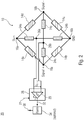
- Fig. 2 shows a schematic block diagram of an electrical circuit 20 according to another embodiment.
- the electrical circuit 20 comprises the electrical circuit 10 as described in connection with FIG Fig. 1 and a comparator 28 connected to the first tap 26a and the second tap 26b.
- the comparator 28 is designed to perform a comparison between the first voltage potential at the first tap 26a and the second voltage potential at the second tap 26b. This can be done so that a respective voltage potential at the tap 26a and the tap 26b is detected against a reference voltage, for example 0 V or ground (ground GND) and compared against each other. Alternatively, the two voltage potentials at the taps 26a and 26b can be directly compared.
- a differential voltage U DRIFT is established , which is detected by the comparison device 28.
- the voltage U DRIFT has a value of 0 V or approximately 0 V.
- the comparator 28 is configured to provide an output signal 32 indicative of an error of one of the strain gages 14a-14d of the full-bridge DMS circuit.
- the comparator may be configured to provide the output signal 32 based on the comparison of the voltage potentials to indicate an error of one of the resistors 24a-24d.
- the outputting of the output signal may be conditional, such as when the comparator has logic.
- the comparison device 28 may have a comparator 29, for example to check the fulfillment of a condition (reaching, falling below or exceeding a threshold value) of the output signal and / or to output the output signal 32 in a digitized form.
- the output signal 32 may also be a boosted, unamplified or damped version of the voltage waveform of the voltage U DRIFT .
- the comparison device 28 may have a microcontroller with at least two A / D differential transducers (not shown here), the AD differential transducers having the first tap 26a and the second tap 26b and also the signal connections 18a (signal +). and 18b (signal) are connected.
- the microcontroller also has the usual peripherals such as a CPU, a memory (RAM, ROM) for storing program code and other data, etc. With the microcontroller, the fulfillment of a condition (reaching, falling below or exceeding a threshold value) of the output signal can also be checked and / or the output signal 32 can be output in a digitized form.
- the output signal 32 may also be a boosted, unamplified or damped version of the voltage waveform of the voltage U DRIFT .
- the microcontroller can also be integrated a temperature sensor or sensor. However, it is also conceivable to connect to the microcontroller a separate and / or additional temperature sensor or sensor or temperature-dependent resistor.
- the comparator 28 is configured to provide the output signal 32 when a resistor 24a-24d or a strain gauge 14a-14d has an error.
- a fault may be, for example, a mechanical or electrical damage to a resistor 24a-24d or strain gauge 14a-14d.
- a strain gauge may also be considered defective if a substrate or material to which the strain gage 14a-14d is attached has a local deformation such that the strain gage is deformed in at least one, several, or all loading states Substrate has a different resistance from other strain gauges.
- Other failures that can be detected are faulty connection points between lines and strain gauges or resistors or age-related changes in the elements, for example due to material fatigue. Even if some of these faults are outside the strain gages or resistors, they can be detected because they affect the electrical conductivity of the circuit or its symmetry.
- the electrical circuit 20 may include an optional alarm signal generator 34 configured to receive the output signal 32 and to output an alarm signal 36.
- the alarm signal may be any signal, such as electrical or optical. Between the output of the alarm signal 36 and the output signal 32, any conditioning can be stored in the alarm signal transmitter 34.
- the alarm signal generator may be configured to output the alarm signal 36 when an amplitude, frequency or current value of the output signal 32 reaches or exceeds a threshold value.
- the output signal 32 is directly or indirectly proportional to the amplitude of the voltage U DRIFT and in the alarm signal transmitter 34 a threshold value to be reached or exceeded.
- the alarm signal generator is configured to output the alarm signal 36 when the output signal 32 is present or off, such as when the comparator 28 is configured to output the output signal 32 when an amplitude of the voltage U DRIFT reaches or exceeds the threshold.
- the alarm can also be formed as part of the comparator 26.
- the comparator 28 may be configured to receive temperature information 31.
- the temperature information may indicate a temperature at one or more resistors 24a-24d.
- the comparison device may be configured to correct a temperature-based change of a resistor or a plurality of resistors to be corrected based on the temperature information 31 with respect to a resistance value.
- the comparison device 28 can thus be designed to respect a corresponding potential at the tap 26a and / or 26b. Correct the temperature-induced change in the resistance value accordingly.
- a temperature characteristic of the resistors and / or reference resistors 24a-24d may be deposited in the comparator.
- the differential voltage of the reference bridge ie the voltage U DRIFT can be digitized by an A / D converter (analog-to-digital converter). After a temperature correction has been obtained, this (corrected) measured value can be correlated with a load state of a device on which the full-bridge DMS 12 is arranged, for example the reference state or 0 kg. Any change around 0 kg can be interpreted as a drift in kilograms, ie as a mechanical load on the full bridge DMS circuit 12, if the resistors use the same calibration factor used to calculate the actual load on the DMS bridge.
- the application of a previously stored temperature characteristic to the output signal of the two voltage dividers or resistor series circuits 22a and 22b as a function of the currently measured temperature eliminates a temperature influence on the resistors 24a / 24b and 24c / 24d.
- the temperature characteristic can be realized as a list of correction factors related to the respective temperature (so-called look-up table) or determined or determined during operation. With the application of the temperature characteristic, an always equal output voltage of the voltage dividers 22a and 22b is achieved over the entire temperature range.
- Fig. 3a shows a first state of the electrical circuit 10 with applied supply voltage.
- the first state there are an unloaded case of the full-bridge DMS circuit 12 and error-free components thereof and the two resistor series circuits.
- the voltage U BATT relative to the reference voltage GND has a voltage difference of 5V.
- any supply voltage to the strain gage full bridge circuit 12 can be applied, for example at least 0.1 V and at most 1000 V, at least 1 V and at most 100 V or at least 2.5 V and at most 20 V.
- the supply voltage U BATT drops in equal parts across the strain gauges 14a and 14b and equally over the DMS 14c and 14d from.
- Half of the supply voltage ie 2.5 V
- the supply voltage U BATT likewise drops in equal parts via the symmetrical, ie identical, resistors 24a and 24b, so that a voltage of 2.5 V is likewise present at the tap 26a.
- the drift voltage U DRIFT between the taps 26a and 26b is thus 0 V.
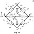
- Fig. 3b shows the electrical circuit 10 in a second case, the mechanical load on the cell, d h. the strain gauge full bridge circuit 12 describes.
- the resistance values of the strain gauges 14a and 14b or 14c and 14d can each change in opposite directions.
- the strain gauge 14a may have a reduced resistance and the strain gauge 14b may have an increased resistance value.
- a potential of 2.6 V is applied to the terminal 18a.
- a potential of 2.4 V is applied to the terminal 18b.
- This signal difference is ideally symmetrical about the average voltage of 2.5 V applied to the tap 26b.
- the resistors 24a-24d are independent of the mechanical deformation, so that the potential at the center tap 26a continues to be 2.5 V, so that the voltage U DRIFT is still 0 V. This means that in the loaded case, the auxiliary voltages can still be the same.
- the strain gages 14a-14d can change smoothly in the loaded case.
- the voltage Signal + at the terminal 18a becomes greater and the voltage Signal- at the terminal 18b becomes smaller.
- the signal voltage of the full-bridge DMS circuit 12 changes according to the difference.
- the auxiliary voltages adjust here again to 2.5 V from the equilibrium principle.
- the test voltage will remain at 0 V as in the unloaded state.
- the drift voltage U DRIFT can also be used in the loaded case of the full-bridge strain gauge circuit 12 as an indicator of the integrity of the elements.
- the comparator may be configured to provide the output independent of deformation of the strain gauges 14a-14d.
- the comparison device can be designed to make the comparison in a reference state as described in US Pat Fig. 3a is shown, and in a load state, as in Fig. 3b is shown to execute the DMS full bridge circuit 12.
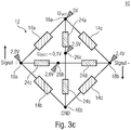
- FIG. 12 shows the electrical circuit 10 in a third state in which the strain gages 14a-14d are mechanically deformed to change their resistance as described in connection with FIG Fig. 3b is described.
- the full-bridge DMS circuit 12 has a fault condition, which in the present example is obtained by the strain gage 14a changing its resistance independently of a load condition such as damage or aging.
- the strain gauge 14a has reduced its resistance.
- a voltage of 2.4V is obtained at the terminal 18b whose DMS path is unaffected. Due to the asymmetry of the strain gauges 14a and 14b, however, another, approximately higher potential arises at the connection 18a. For example.
- the potential is still at 2.5V. Due to the changed voltage at the terminal 18a, however, the electrical potential at the tap 26b is different therefrom, so that by way of example a differential voltage U DRIFT of 0.1 V results. This can be detected by the comparator and information based thereon can be output by the output signal.
- auxiliary voltages at the taps 26a and 26b are no longer equal. Since the auxiliary voltage between the signal terminals 18a and 18b adjusts to an average of 2.6V, the difference becomes between the auxiliary voltages no longer be 0 V. This can be interpreted as a signal that the cell - independently of load - has undergone a zero-point drift.
- a threshold voltage can be adjusted via a comparator, such as the comparator 29, so that a minimum deviation (threshold) of the drift voltage U DRIFT must first be reached or exceeded, so that an output signal and / or error signal is generated.
- the comparator may be configured to output the output signal such that if the voltage potential at the tap 26a and the voltage potential at the tap 26b are equal, it indicates that there is no drift and that the voltage potentials at the taps 26a and 26b are inequality indicating that there is a drift in the electrical circuit.
- an arranged comparison device 28 may be designed to correct one or more of the signals obtained with respect to temperature-induced changes of the resistors 24a-d.
- the following consideration is used in the following, wherein the stated values are to be understood as illustrative and not restrictive.
- the full-bridge DMS circuit 12 is configured to obtain a signal change 1 mV / V at 1000 kg load on a structure where the full-bridge DMS 12 corresponds, the following scenario can be obtained with an exemplary supply voltage of 5 V of the full-bridge DMS:
- a strain gauge within the measuring bridge can change in such a way due to aging, manufacturing tolerances or damage that the measuring bridge delivers a signal change of the equivalent of 1 kg. This corresponds to a signal voltage change between signal + and signal - of 5 ⁇ V.
- the center voltage of the two reference resistors 24c and 24d between the terminals 18a and 18b will accordingly undergo a change of 2.5 ⁇ V.
- Such misinformation may result in a late or premature alarm signal or error behavior of a controller.
- resistors can often or even always be subject to temperature dependence. Not only can the amount of dependency differ, but also its direction (sign). For example, with a positive temperature change, three out of four resistors may experience an increase in resistance, and the fourth resistance may experience a decrease in resistance. Therefore, it may be useful, as stated above, to perform a comparison with one or more reference resistors, which have a predetermined or permissible temperature dependence. This temperature dependence or the range within which a resistance value of a reference resistor moves with a temperature change can be within the permissible total error limits which result for the reference resistances from tolerance, temperature dependence, etc.
- a further advantage of exemplary embodiments described above is that the function of the resistors 24a-d can also be checked and / or monitored. Should a resistor of a resistor series circuit change, for example due to production or aging technical reasons or due to damage, then the function of the electrical circuit, i. H. drift indicator, not at risk. A drift signal other than 0 V, which differs from the normal state, is nevertheless output in this case, although the cause is not in the strain gauges 14a-14d. However, this can still be understood that a review of the electrical circuit 10 is required. In terms of safety, a one-fault case for strain gages and resistors can thus be covered. Furthermore, self-monitoring of the monitoring elements, i. H. the resistors 24a-24d are obtained.
- Fig. 4 shows a schematic perspective view of a load cell 40 according to an embodiment.
- the load cell 40 includes the electrical circuit 10.
- the load cell 40 may also include the electrical circuit 20.
- the load cell 40 has a first side 42 and a second side 44, which are connectable to different mechanical components.
- one side may be connected to a base and the other side to a reference structure.
- the reference structure can it is a working platform, a weighing pan or scale level for weighing an object or the like.
- a movement of the different mechanical components to each other or a force acting on at least one of the different mechanical components and thus on at least one of the sides 42 or 44, can lead to a load on the load cell 40, to a deformation of components thereof and thus to a load the strain gauge full bridge circuit 12 lead.
- the force may alternatively or additionally also be a weight force, i. That is, based on the load cell 40, a weight load of the first side 42 relative to the second side 44 or vice versa may be detectable.
- Embodiments relate to load sensing devices.
- Load sensing devices are, for example, designed to detect a load acting on an element or device.
- One application of load sensing devices are hoisting machines designed to lift a load.
- Exemplary hoisting machines are cranes, (fork) forklifts, garbage or container vehicles or wheel loaders, this list is not exhaustive.
- Load sensing devices for hoisting machines according to embodiments described herein include, for example, a mechanism for moving a load such as a crane, a hoist or the like.
- the mechanism is attachable to a base, such as a vehicle or structure to which the load is to be moved.
- a load cell is arranged between the mechanism and the load.
- the mechanism and the load are interconnected by the load cell, so that a load of the load on the mechanism and / or from the mechanism to the load can be precisely detected.
- an electrical circuit or load cell may be connected to hoisting machines where load and / or weight sensing is desirable, such as aerial work platforms or other industrial applications, ie, devices or systems.
- a load cell is connected to vehicles such as a forklift truck, a refuse vehicle (such as a load cell for weighing a ton), a wheel loader (such as or in combination with pressure sensors on at least one hydraulic cylinder thereof)
- a vehicle has a load sensing device for a (lifting) mechanism. Between the mechanism and the load, for example, the electronic circuit or the load cell is arranged.
- Fig. 5a shows a schematic view of a load sensing device 50 for a load 52, for example.
- the load detection device 50 comprises a mechanism 54, for example a crane mechanism for moving the working platform 52, ie the working platform 52 can be realized as an aerial work platform.
- the crane mechanism 54 is attachable to a base. Between the crane mechanism 54 and the work platform 52, the load cell 40 is arranged.
- the work platform 52 and the crane mechanism 54 are interconnected by the load cell 40. That is, a mechanical connection exists between the work platform 52 and the crane mechanism 54 via the load cell 40.
- a force F for example, by their weight and / or a loading thereof, which leads to a load on the crane mechanism 54 , which is detectable via the load cell 40.
- any other (possibly external) force acting on the work platform and be detected.
- Fig. 5b shows the junction between the platform 52 and the crane mechanism 54 in an enlarged view.
- the first side 42 of the load cell is connected to the work platform 52.
- the second side 44 of the load cell is connected to the crane mechanism 54.
- angle plates or other mechanical connecting elements may be arranged to establish a mechanical connection between the working platform 52 or the crane mechanism 54 and the weighing cell.
- the location of the load cell 40 between the crane mechanism 54 and the work platform 52 enables detection of a load that the work platform 52 exerts on the crane mechanism 54, such as by a weight of the work platform 52.
- Fig. 6 shows a schematic representation of a vehicle 60, on the chassis of the load detection device 50 is arranged.
- the base of the crane mechanism 54 is attached to the vehicle chassis 62.
- the electrical circuit of the load cell 40 can in a particularly simple and reliable manner secure operation of the load sensing device 50 and the crane mechanism 54 allow as in each operating state of the crane mechanism 54, ie in a loaded state thereof or in a loaded state of the load cell 40 a Function check of the electrical circuit can be done, ie, it can be determined whether there is a drift in the DMS full bridge circuit.
- a crane mechanism can also be realized as a (construction) crane or as a crane mounted on a building and combined with a weighing cell described herein.
- a load condition of any structure may be detected or monitored.
- Embodiments described herein provide an indicator that enables detection of a disturbance or destruction of the balance of the DMS full bridge circuit and other Wheatstone bridge circuits and provides a corresponding signal regardless of load.
- Two auxiliary voltages are generated by means of the two voltage dividers in the resistor series circuits. In an ideal full bridge, the difference between these two voltages is 0 V.
- This test voltage U DRIFT is used to identify a deviation as drift. Simplified, a voltage of 0 V or nearly 0 V can be interpreted as "there is no drift before” and a voltage of greater or lesser than 0 V is interpreted as "there is a drift before”.
- the zero point drift of the cell ie the full-bridge strain gage circuit
- the zero point drift of the cell can be measured at any point in time or in any operating state, loaded or unloaded.
- the total cell drift can be computationally eliminated at any point in time or in any operating state.
- aspects have been described in the context of a device, it will be understood that these aspects also constitute a description of the corresponding method, so that a block or a component of a device is also to be understood as a corresponding method step or as a feature of a method step. Similarly, aspects described in connection with or as a method step also represent a description of a corresponding block or detail or feature of a corresponding device.
Landscapes
- Physics & Mathematics (AREA)
- General Physics & Mathematics (AREA)
- Engineering & Computer Science (AREA)
- Structural Engineering (AREA)
- Mechanical Engineering (AREA)
- Life Sciences & Earth Sciences (AREA)
- Geology (AREA)
- Business, Economics & Management (AREA)
- Emergency Management (AREA)
- Measurement Of Force In General (AREA)
Description
Die vorliegende Erfindung bezieht sich auf eine elektrische Schaltung mit einer DMS-Vollbrückenschaltung, auf eine Wägezelle, auf eine Lasterfassungsvorrichtung, beispielsweise für eine Arbeitsbühne, und auf ein Fahrzeug mit einer Lasterfassungsvorrichtung. Die vorliegende Erfindung bezieht sich insbesondere auf einen Drift-Indikator zur Überwachung des Gleichgewichts innerhalb der Wheatstone'schen DMS-Vollbrücke.The present invention relates to an electrical circuit with a full-bridge strain gage, to a load cell, to a load sensing device, for example for a working platform, and to a vehicle having a load sensing device. More particularly, the present invention relates to a drift indicator for monitoring equilibrium within the Wheatstone DMS full bridge.
Vollbrückenschaltungen mit DMS-Elementen (DMS = Dehnungsmessstreifen) können eingesetzt werden, um Belastungszustände an mechanisch verformbaren Elementen festzustellen. Ein Beispiel hierfür ist eine Wägezelle, die zwischen einer Arbeitsbühne und einem Kran angeordnet ist, wobei durch eine Verformung von Elementen der Wägezelle auf eine Belastung des Krans durch die Arbeitsbühne geschlossen werden kann.Full bridge circuits with DMS elements (strain gauges) can be used to determine load conditions on mechanically deformable elements. An example of this is a load cell, which is arranged between a work platform and a crane, wherein it can be concluded by a deformation of elements of the load cell on a load of the crane by the working platform.
In einer korrekt arbeitenden Wägezelle mit einer DMS-Vollbrücke herrscht bezüglich der auftretenden elektrischen Spannungen ein Gleichgewicht. Ein Nullpunktdrift zerstört dieses Gleichgewicht, so dass ein durch die elektrischen Spannungen messbarer Belastungszustand von einem tatsächlichen Belastungszustand abweicht. Dies kann dazu führen, dass der Kran überlastet wird, da eine Überlast zu spät angezeigt wird.In a correctly working load cell with a strain gauge full bridge there is an equilibrium with respect to the occurring electrical voltages. Zero-point drift destroys this balance so that a load state measurable by the electrical voltages deviates from an actual load condition. This can cause the crane to become overloaded because overload is displayed too late.
Um solche Fehlindikationen zu vermeiden, werden redundante DMS-Vollbrücken eingesetzt, um einen Nullpunktdrift einer DMS-Vollbrücke durch eine andere zu erkennen. Dies hat jedoch zum Nachteil, dass bei abweichenden Ergebnissen der beiden redundanten DMS-Vollbrückenschaltungen nur ein abweichendes Ergebnis erhalten wird, das aber auch auf unterschiedliche Materialdehnungen an unterschiedlichen Orten der unterschiedlichen DMS-Vollbrücken zurückgeführt werden kann. Ferner müssen mehrere Vollbrückenschaltungen angeordnet und ausgewertet werden.In order to avoid such misindications, redundant full-bridge strain gauges are used to detect a zero-point drift of a strain gauge full-bridge through another. However, this has the disadvantage that, if the results of the two redundant strain gauge full bridge circuits differ, only a different result is obtained, but this can also be attributed to different material expansions at different locations of the different strain gauge full bridges. Furthermore, several full bridge circuits must be arranged and evaluated.
Manche Konzepte gemäß dem Stand der Technik sehen eine Überprüfung des Ausgangssignals der Vollbrückenschaltung in einem unbelasteten Zustand vor. Eine Abweichung des Signalwertes von einem Nullwert kann als Nullpunktdrift erkannt werden. Jedoch ist dies im Betrieb nicht möglich, da durch den Betrieb selbst ein Signalwert erhalten wird, der von dem Nullwert verschieden ist.Some prior art concepts provide for a check of the output of the full bridge circuit in an unloaded state. A deviation of the signal value from a zero value can be recognized as a zero point drift. however this is not possible in operation, since the operation itself gives a signal value which is different from the zero value.
In
In
In
In
Wünschenswert wäre demnach ein Konzept, das es ermöglicht, eine Betriebsbereitschaft einer DMS-Vollbrücke zuverlässig zu erkennen oder sicherzustellen.It would therefore be desirable to have a concept which makes it possible to reliably detect or ensure readiness for operation of a strain gauge full bridge.
Diese Aufgabe wird durch den Gegenstand der unabhängigen Patentansprüche gelöst.This object is solved by the subject matter of the independent patent claims.
Der Kerngedanke der vorliegenden Erfindung besteht darin, erkannt zu haben, dass eine Symmetrie einer Vollbrückenschaltung durch eine symmetrische Widerstandsschaltung, die mit den Toren der Vollbrückenschaltung verbunden ist, überwachbar ist, indem Widerstandsserienschaltungen so angeordnet werden, dass zwischen Widerständen der Widerstandsserienschaltungen ebenfalls paarweise und symmetrisch zueinander Spannungen erzeugt werden, die von der Symmetrie der Vollbrückenschaltung beeinflusst sind und einen Hinweis auf den Zustand der Vollbrückenschaltungen ermöglichen.The gist of the present invention is to have recognized that symmetry of a full bridge circuit can be monitored by a balanced resistor circuit connected to the gates of the full bridge circuit by arranging resistor series circuits such that between resistors of the resistor series circuits are also paired and symmetrical with each other tensions are generated, which are influenced by the symmetry of the full bridge circuit and allow an indication of the state of the full bridge circuits.
Gemäß einem Ausführungsbeispiel der vorliegenden Erfindung umfasst eine elektrische Schaltung eine DMS-Vollbrückenschaltung, eine erste Widerstandsserienschaltung und eine zweite Widerstandsserienschaltung. Die erste Widerstandsserienschaltung ist zwischen die Anschlüsse eines Energieversorgungstores der DMS-Vollbrückenschaltung geschaltet und weist einen ersten Abgriff zwischen zwei Widerständen auf. Die zweite Widerstandsserienschaltung ist zwischen die Anschlüsse eines Signaltores der DMS-Vollbrückenschaltung geschaltet und weist einen zweiten Abgriff zwischen zwei Widerständen auf. In einem Betrieb der elektrischen Schaltung kann zwischen dem ersten Abgriff und dem zweiten Abgriff eine Spannung erhalten werden, die einen Umfang des Nullpunktdrifts angibt. Vorteilhaft an diesem Ausführungsbeispiel ist, dass die Driftspannung unabhängig von einer Belastung der DMS-Vollbrückenschaltung ist, so dass der Nullpunktdrift auch während Belastungszuständen der DMS-Vollbrückenschaltung erkannt werden kann.According to an embodiment of the present invention, an electrical circuit comprises a full-bridge strain gage, a first series resistance circuit, and a second series resistance circuit. The first resistor series circuit is connected between the terminals of a power supply gate of the DMS full bridge circuit and has a first tap between two resistors. The second resistor series circuit is connected between the terminals of a signal gate of the DMS full bridge circuit and has a second tap between two resistors. In one operation of the electrical circuit, a voltage may be obtained between the first tap and the second tap indicating a magnitude of the zero drift. An advantage of this embodiment is that the drift voltage is independent of a load of the strain gauge full bridge circuit, so that the zero point drift can also be detected during load conditions of the strain gauge full bridge circuit.
Gemäß weiteren Ausführungsbeispielen umfasst die elektrische Schaltung eine Vergleichseinrichtung, die mit dem ersten Abgriff und dem zweiten Abgriff verbunden ist, und die ausgebildet ist, um einen Vergleich zwischen einem ersten Spannungspotential an dem ersten Abgriff und einem zweiten Spannungspotential an dem zweiten Abgriff auszuführen. Vorteilhaft daran ist, dass die Vergleichseinrichtung durch Vergleich der beiden Spannungspotentiale eine Differenzspannung zwischen den Spannungspotentialen messen oder bestimmten kann und so einen Drift der Vollbrückenschaltung erfassen kann.According to further embodiments, the electrical circuit comprises a comparator connected to the first tap and the second tap and configured to make a comparison between a first voltage potential at the first tap and a second voltage potential at the second tap. The advantage of this is that the comparison device by comparing the two Voltage potentials can measure or determine a differential voltage between the voltage potentials and so can detect a drift of the full bridge circuit.
Gemäß weiteren Ausführungsbeispielen ist die Vergleichseinrichtung ausgebildet, um basierend auf dem Vergleich der Spannungspotentiale ein Ausgangssignal bereitzustellen, das einen Fehler eines der DMS der DMS-Vollbrückenschaltung anzeigt. Vorteilhaft daran ist, dass das Ausgangssignal für andere Vorrichtungen bereitstellbar und von diesen verwendbar ist, um einen Betrieb einer Gerätschaft, deren Zustand mit der elektrischen Schaltung überwacht werden soll, zu beeinflussen, etwa eine Kranvorrichtung.According to further embodiments, the comparator is configured to provide an output indicative of an error of one of the strain gages of the full-bridge strain gauge circuit based on the comparison of the voltage potentials. Advantageously, the output signal can be provided to and used by other devices to affect operation of a device whose condition is to be monitored by the electrical circuit, such as a crane device.
Gemäß weiteren Ausführungsbeispielen ist die Vergleichseinrichtung ausgebildet, um basierend auf dem Vergleich ein Ausgangssignal bereitzustellen, das einen Fehler eines der Widerstände der ersten oder zweiten Widerstandsserienschaltung anzeigt. Eine Verschiebung eines Gleichgewichts und/oder einer Symmetrie der Widerstandsserienschaltungen zueinander oder innerhalb der jeweiligen Widerstandsserienschaltung kann zu einer Verschiebung des ersten oder zweiten Spannungspotentials und zum Auftreten einer Driftspannung führen. Vorteilhaft daran ist, dass die überwachenden Komponenten, d. h. die Widerstandsserienschaltungen, ebenfalls mit überwacht werden können.According to further embodiments, the comparison means is adapted to provide an output indicative of an error of one of the resistors of the first or second resistor series circuit based on the comparison. A shift of equilibrium and / or symmetry of the resistive series circuits to each other or within the respective resistor series circuit may result in a shift of the first or second voltage potential and the occurrence of a drift voltage. The advantage of this is that the monitoring components, i. H. the resistor series circuits can also be monitored with.
Gemäß weiteren Ausführungsbeispielen ist die Vergleichseinrichtung ausgebildet, um das zweite Spannungspotential bezüglich einer temperaturbasierten Veränderung eines Widerstands der ersten oder zweiten Widerstandsserienschaltung zu korrigieren, um eine Temperaturinformation zu empfangen, die eine Temperatur an dem zu korrigierenden Widerstand anzeigt, und um die temperaturbasierte Veränderung des zu korrigierenden Widerstands basierend auf der Temperaturinformation zu korrigieren. Vorteilhaft daran ist, dass Fehler der Referenzwiderstände der Widerstandsserienschaltungen durch Temperaturänderung kompensierbar sind, so dass eine Zuverlässigkeit der elektrischen Schaltung hoch ist.According to further embodiments, the comparison means is arranged to correct the second voltage potential with respect to a temperature-based variation of a resistance of the first or second resistor series circuit, to receive temperature information indicative of a temperature at the resistor to be corrected, and the temperature-based variation of the one to be corrected To correct resistance based on the temperature information. The advantage of this is that errors of the reference resistors of the resistor series circuits can be compensated by temperature change, so that reliability of the electrical circuit is high.
Gemäß weiteren Ausführungsbeispielen ist die Vergleichseinrichtung ausgebildet, um ein Ausgangssignal bereitzustellen, wenn ein Vergleichswert des Vergleichs einen Schwellwert erreicht oder überschreitet. Vorteilhaft daran ist, dass das Ausgangssignal und/oder ein Fehlersignal erst generiert wird, wenn der Schwellwert erreicht oder überschritten ist. So können innerhalb von Toleranzen liegende Veränderungen der Elemente und/oder Herstellungstoleranzen kompensiert und fehlerhafte Alarmsignale vermieden werden.According to further embodiments, the comparison device is designed to provide an output signal when a comparison value of the comparison reaches or exceeds a threshold value. The advantage of this is that the output signal and / or an error signal is generated only when the threshold is reached or exceeded. Thus, changes in the elements and / or manufacturing tolerances lying within tolerances can be compensated and erroneous alarm signals can be avoided.
Weitere Ausführungsbeispiele der vorliegenden Erfindungen schaffen eine Wägezelle mit einer ersten Seite und einer zweiten Seite. Die Wägezelle weist eine elektrische Schaltung gemäß hierin beschriebenen Ausführungsbeispielen auf, die ausgebildet ist, um basierend auf einer mechanischen Belastung an der ersten Seite basierend auf einer Kraft, die auf die zweite Seite wirkt, ein Signal an dem Signaltor der elektrischen Schaltung bereitzustellen. Vorteilhaft daran ist, dass ein Drift in der Wägezelle effizient und platzsparend erkannt werden kann, da auf eine Anordnung einer zweiten Vollbrückenschaltung verzichtet werden kann. Ferner kann ein auftretender Nullpunktdrift auch in einem Betrieb der Wägezelle erkannt werden.Further embodiments of the present invention provide a load cell having a first side and a second side. The load cell includes an electrical circuit according to embodiments described herein that is configured to provide a signal at the signal gate of the electrical circuit based on a mechanical load on the first side based on a force acting on the second side. The advantage of this is that a drift in the load cell can be detected efficiently and in a space-saving manner, since it is possible to dispense with an arrangement of a second full-bridge circuit. Furthermore, an occurring zero-point drift can also be detected in an operation of the load cell.
Weitere Ausführungsbeispiele der vorliegenden Erfindung schaffen eine Lasterfassungsvorrichtung für eine Arbeitsbühne mit einem Kranmechanismus zum Bewegen der Arbeitsbühne, wobei der Kranmechanismus an einer Basis befestigbar ist, und einer zwischen dem Kranmechanismus und der Arbeitsbühne angeordneten Wägezelle. Der Kranmechanismus und die Arbeitsbühne sind durch die Wägezelle miteinander verbunden sind. Vorteilhaft daran ist, dass die Belastung des Kranmechanismus durch die Arbeitsbühne mittels der Wägezelle, die die elektrische Schaltung aufweist, in einem Betrieb des Kranmechanismus erfassbar ist. Eine turnusmäßige, bspw. jährliche, Überprüfung der Wägezelle kann hierdurch gegebenenfalls ganz entfallen bzw. ist nur noch im Fehlerfall (auftretender Nullpunktdrift) erforderlich. Alternativ kann der Überprüfungsintervall der Wägezelle in vorteilhafter Weise verlängert werden, bspw. alle zwei Jahre. Somit werden mit der vorliegenden Erfindung auch einige Kosten eingespart.Further embodiments of the present invention provide a load detection apparatus for a work platform with a crane mechanism for moving the work platform, the crane mechanism being attachable to a base, and a load cell disposed between the crane mechanism and the work platform. The crane mechanism and the work platform are interconnected by the load cell. The advantage of this is that the load of the crane mechanism by the working platform by means of the load cell, which has the electrical circuit, in an operation of the crane mechanism can be detected. A regular, eg annual, check of the load cell can thereby possibly be completely eliminated or is only required in the event of a fault (occurring zero-point drift). Alternatively, the check interval of the load cell may advantageously be extended, for example every two years. Thus, some costs are saved with the present invention.
Weitere Ausführungsbeispiele der vorliegenden Erfindung schaffen ein Fahrzeug mit einer Lasterfassungsvorrichtung gemäß hierin beschriebenen Ausführungsbeispielen. Der Kranmechanismus ist an einem Fahrzeugchassis befestigt.Further embodiments of the present invention provide a vehicle having a load sensing device according to embodiments described herein. The crane mechanism is attached to a vehicle chassis.
Bevorzugte Weiterbildungen der vorliegenden Erfindung sind in den Unteransprüchen definiert.Preferred developments of the present invention are defined in the subclaims.
Bevorzugte Ausführungsbeispiele der vorliegenden Erfindung werden nachfolgend Bezug nehmend auf die beiliegenden Zeichnungen erläutert. Es zeigen:
- Fig. 1
- ein schematisches Blockschaltbild einer elektrischen Schaltung gemäß einem Ausführungsbeispiel;
- Fig. 2
- ein schematisches Blockschaltbild einer elektrischen Schaltung gemäß einem weiteren Ausführungsbeispiel;
- Fig. 3a
- einen ersten Zustand der elektrischen Schaltung gemäß
Fig. 1 bei angelegter Versorgungsspannung; - Fig. 3b
- die elektrische Schaltung aus
Fig. 3a bei einer mechanischen Belastung der Zelle; - Fig. 3c
- die elektrische Schaltung aus
Fig. 3b bei einem auftretenden Fehler; - Fig. 4
- eine schematische perspektivische Ansicht einer Wägezelle gemäß einem Ausführungsbeispiel;
- Fig. 5a
- eine schematische Ansicht einer Lasterfassungsvorrichtung gemäß einem Ausführungsbeispiel;
- Fig. 5b
- eine Verbindungsstelle zwischen einer Arbeitsbühne und einem Kranmechanismus aus
Fig. 5a in vergrößerter Darstellung; und - Fig. 6
- eine schematische Darstellung eines Fahrzeugs gemäß einem Ausführungsbeispiel.
- Fig. 1
- a schematic block diagram of an electrical circuit according to an embodiment;
- Fig. 2
- a schematic block diagram of an electrical circuit according to another embodiment;
- Fig. 3a
- a first state of the electrical circuit according to
Fig. 1 with applied supply voltage; - Fig. 3b
- the electrical circuit
Fig. 3a at a mechanical load of the cell; - Fig. 3c
- the electrical circuit
Fig. 3b in the event of an error occurring; - Fig. 4
- a schematic perspective view of a load cell according to an embodiment;
- Fig. 5a
- a schematic view of a load detection device according to an embodiment;
- Fig. 5b
- a connection point between a working platform and a crane mechanism
Fig. 5a in an enlarged view; and - Fig. 6
- a schematic representation of a vehicle according to an embodiment.
Bevor nachfolgend Ausführungsbeispiele der vorliegenden Erfindung im Detail anhand der Zeichnungen näher erläutert werden, wird darauf hingewiesen, dass identische, funktionsgleiche oder gleichwirkende Elemente, Objekte und/oder Strukturen in den unterschiedlichen Figuren mit den gleichen Bezugszeichen versehen sind, so dass die in unterschiedlichen Ausführungsbeispielen dargestellte Beschreibung dieser Elemente untereinander austauschbar ist bzw. aufeinander angewendet werden kann.Before embodiments of the present invention are explained in more detail in detail with reference to the drawings, it is pointed out that identical, functionally identical or equivalent elements, objects and / or structures in the different figures are provided with the same reference numerals, so that shown in different embodiments Description of these elements is interchangeable or can be applied to each other.
Nachfolgen beschriebene Ausführungsbeispiele beziehen sich auf einen Drift oder einen Nullpunktdrift einer Vollbrückenschaltung. Der Drift oder Nullpunktdrift bezieht sich auf eine Abweichung einer an der Vollbrückenschaltung erfassbaren Messspannung von einer Sollspannung in einem Referenzzustand. Der Referenzzustand kann als unbelasteter Zustand oder Kalibrierzustand verstanden werden. Ausgehend von dem Referenzzustand kann sich mit zunehmender (mechanischer) Belastung der Vollbrückenschaltung ein erstes Signal in dem Maße erhöhen, in dem sich ein zweites Signal verringert, so dass ein zunehmender Betrag einer Spannungsdifferenz ein Maß für die Belastung der Vollbrückenschaltung darstellt. Im Referenzzustand kann eine Referenzspannung, etwa eine Spannungsdifferenz von 0 V vorliegen. Durch Fehler in der Vollbrückenschaltung kann in dem Referenzzustand eine Spannungsdifferenz von ungleich 0 V auftreten, was nachfolgend als Drift oder Nullpunktdrift der Vollbrückenschaltung bezeichnet wird.Embodiments described below relate to a drift or a zero-point drift of a full-bridge circuit. The drift or zero point drift relates to a deviation of a measurement voltage that can be detected at the full bridge circuit from a setpoint voltage in a reference state. The reference state can be understood as an unloaded state or calibration state. Starting from the reference state, with increasing (mechanical) load of the full bridge circuit, a first Increase signal to the extent that a second signal decreases so that an increasing amount of voltage difference is a measure of the load on the full bridge circuit. In the reference state, a reference voltage, such as a voltage difference of 0 V may be present. Due to errors in the full-bridge circuit, a voltage difference of not equal to 0 V can occur in the reference state, which is referred to below as drift or zero-point drift of the full-bridge circuit.
Die DMS-Vollbrückenschaltung 12 umfasst ferner Signalanschlüsse 18a und 18b, die ein Signaltor der DMS-Vollbrückenschaltung bilden. Das Energieversorgungstor ist mit einer Versorgungsspannung für die DMS 14a-14d verbindbar, woraufhin basierend auf einer Veränderung eines Zustands der DMS ein Signal an dem Signaltor erhalten werden kann. Bei dem Zustand kann es sich um einen Belastungszustand handeln, der zu einer Dehnung oder Stauchung der DMS führt.The full-
Die elektrische Schaltung 10 umfasst ferner eine erste Widerstandsserienschaltung 22a, die zwischen die Anschlüsse 16a und 16b geschaltet ist. Die Widerstandsserienschaltung 22a umfasst zwei seriell verschaltete Widerstände 24a und 24b, zwischen denen ein Abgriff 26a angeordnet ist. An dem Abgriff 26a ist ein Potential zwischen den Widerständen 24a und 24b abgreifbar oder messbar.The
Eine zweite Widerstandsserienschaltung 22b ist zwischen die Anschlüsse 18a und 18b geschaltet und umfasst zwei in Serie verschaltete Widerstände 24c und 24d, zwischen denen ein Abgriff 26b angeordnet. An dem Abgriff 26b ist ein Potential zwischen den Widerständen 24c und 24d abgreifbar oder messbar.A second
Vorzugsweise sind die DMS 14a-14d gleich ausgebildet. Das bedeutet, dass eine mechanische und/oder elektrische Abweichung zwischen den DMS 14a-14d gering, näherungsweise 0 oder gleich 0 ist. Vorzugsweise sind die Widerstände 24a-24d gleich ausgebildet. Das bedeutet, sie weisen vorzugsweise einen gleichen Widerstandswert, eine gleiche mechanische Belastbarkeit und/oder eine gleiche temperaturbedingte Widerstandsänderung auf. Gemäß Ausführungsbeispielen ist vorgesehen, dass die Wiederstände auf eine gleiche temperaturbedingte Widerstandsänderung ausgeführt werden können, wie es im Zusammenhang mit
Bei dem DMS kann es sich um elektrische Widerstände handeln, deren Widerstandswerte sich basierend auf einer mechanischen Deformation ändern. Alternativ kann es sich bei den DMS auch um andere dehnungsempfindliche Messelemente handeln, wie etwa um optische DMS, die beispielsweise als Faser-Bragg-Gitter bezeichnet werden. Bei optischen DMS kann eine Dehnung oder Stauchung durch eine Verschiebung von Spektren elektromagnetischer Strahlung festgestellt werden. Diese Verschiebung kann unter Verwendung optoelektronischer Wandler in eine elektrische Spannung überführt werden, so dass die Prinzipien der Vollbrückenschaltung uneingeschränkt auch für optische DMS anwendbar sind.The strain gages can be electrical resistors whose resistance values change based on mechanical deformation. Alternatively, the strain gages can also be other strain-sensitive measuring elements, such as optical strain gages, which are referred to as fiber Bragg gratings, for example. In optical strain gages, strain or strain can be detected by a shift in spectra of electromagnetic radiation. This shift can be converted into an electrical voltage using optoelectronic converters, so that the principles of the full bridge circuit are also fully applicable to optical strain gages.
Hierin beschriebene Ausführungsbeispiele sind auch für andere Vollbrückenschaltungen anwendbar. Anstelle der DMS können Messelemente zur Erfassung einer beliebigen physikalischen Größe, etwa einer Temperatur, eines Drucks oder eines pH-Werts angeordnet werden, die elektrisch leitfähig sind oder ein elektrisches Signal ausgeben. Die Elemente der Widerstandsserienschaltung können durch elektrisch leitende oder ein elektrisches Signal bereitstellende Elemente implementiert werden, die von der physikalischen Größe in einem veränderten Umfang (geringer, näherungsweise nicht oder verstärkt) beeinflusst sind.Embodiments described herein are also applicable to other full bridge circuits. Instead of the strain gauges, measuring elements can be arranged to detect any physical quantity, such as a temperature, pressure or pH, which are electrically conductive or emit an electrical signal. The elements of the resistive series circuit can be implemented by electrically conductive or electrical signal providing elements that are affected by the physical quantity to an altered extent (less, approximately not, or amplified).
Die Widerstände 24a-24d können beliebige Widerstände sein. Vorzugsweise sind die Widerstände 24a-24d aus hochwertigen temperaturstabilen Widerständen gebildet. Der Widerstandswert kann hierbei beliebig sein. Um einen Energieverbrauch der elektrischen Schaltung 10 niedrig zu halten, können jedoch Widerstände verwendet werden, die einen Widerstandswert von zumindest 1 kΩ und höchstens 100 MΩ, von zumindest 5 kΩ und höchstens 80 MΩ oder von zumindest 8 kΩ und höchstens 50 MΩ, beispielsweise 10 kΩ aufweisen. Dies ermöglicht eine hohe Flexibilität in der Leistungsauslegung (engl.: Power Management) der elektrischen Schaltung 10. Dabei ist es auch möglich, dass die Widerstände 24a-24d einen Widerstandswert im Bereich bzw. in der Größenordnung von ungefähr 350 Ω bis 1 kΩ aufweisen und/oder in etwa einem Widerstandswert der DMS entspricht.The
Die Widerstandsserienschaltungen 22a und 22b können jeweils als Spannungsteiler beschrieben werden, an deren Abgriff 26a oder 26b eine Hilfsspannung erhalten und erfasst werden kann. Es wird darauf hingewiesen, dass obwohl die Widerstandsserienschaltungen 22a und 22b jeweils so beschrieben sind, dass sie zwei Widerstände 24a und 24b bzw. 24c und 24d aufweisen, jeder der Widerstände 24a-24d auch durch eine Mehrzahl oder Vielzahl von Widerständen gebildet sein kann. Obwohl hierin erläuterte Ausführungsbeispiele so beschrieben sind, dass an den Abgriffen 26a und 26b im fehlerfreien Fall jeweils die Hälfte der Spannung zwischen den Anschlüssen 16a und 16b bzw. zwischen den Anschlüssen 18a und 18b erhalten wird, sind elektrische Schaltungen gemäß weiteren Ausführungsbeispielen so konfiguriert, dass an den Abgriffen 26a oder 26b ein von (bezogen auf das Versorgungspotential) 50 % verschiedenes Spannungsniveau erhalten wird. Weisen die Widerstände 24a und 24b beispielsweise voneinander verschiedene Widerstandswerte auf, so kann durch den so erhaltenen asymmetrischen Spannungsteiler ein beliebiges Spannungsniveau erhalten werden. Gleiches gilt für die Widerstandsserienschaltung 22b.The
Die Vergleichseinrichtung 28 ist ausgebildet, um ein Ausgangssignal 32 bereitzustellen, das einen Fehler eines der DMS 14a-14d der DMS-Vollbrückenschaltung anzeigt. Alternativ oder zusätzlich kann die Vergleichseinrichtung ausgebildet sein, um basierend auf dem Vergleich der Spannungspotentiale das Ausgangssignal 32 so bereitzustellen, dass es einen Fehler eines der Widerstände 24a-24d anzeigt. Das Ausgeben des Ausgangssignals kann von einer Bedingung abhängig sein, etwa wenn die Vergleichseinrichtung eine Logik aufweist. Beispielsweise kann die Vergleichseinrichtung 28 einen Komparator 29 aufweisen, etwa um das Erfüllen einer Bedingung (Erreichen, Unterschreiten oder Überschreiten eines Schwellwertes) des Ausgangssignals zu überprüfen und/oder, um das Ausgangssignal 32 in einer digitalisierten Form auszugeben. Alternativ kann das Ausgangssignal 32 auch eine verstärkte, unverstärkte oder gedämpfte Version des Spannungsverlaufs der Spannung UDRIFT sein.The
Dabei ist es auch möglich, dass die Vergleichseinrichtung 28 einen Mikrocontroller mit mindestens zwei A/D-Differenzwandler aufweist (hier nicht dargestellt), wobei die AD-Differenzwandler mit dem ersten Abgriff 26a und dem zweiten Abgriff 26b sowie mit den Signalanschlüssen 18a (Signal+) und 18b (Signal-) verbunden sind. Der Mikrocontroller weist weiterhin die übliche Peripherie wie bspw. eine CPU, einen Speicher (RAM, ROM) zur Ablage von Programmcode und weiteren Daten usw. auf. Mit dem Mikrocontroller kann ebenfalls das Erfüllen einer Bedingung (Erreichen, Unterschreiten oder Überschreiten eines Schwellwertes) des Ausgangssignals überprüft werden und/oder das Ausgangssignal 32 in einer digitalisierten Form ausgegeben werden. Alternativ kann das Ausgangssignal 32 auch eine verstärkte, unverstärkte oder gedämpfte Version des Spannungsverlaufs der Spannung UDRIFT sein. Im Mikrocontroller kann weiterhin ein Temperatursensor bzw. -fühler integriert sein. Es ist jedoch auch denkbar, an den Mikrocontroller einen separaten und/oder zusätzlichen Temperatursensor bzw. -fühler oder auch temperaturabhängigen Widerstand anzuschließen.It is also possible for the
Gemäß einer vorteilhaften Weiterbildung ist die Vergleichseinrichtung 28 so konfiguriert, um das Ausgangssignal 32 bereitzustellen, wenn ein Widerstand 24a-24d oder ein DMS 14a-14d einen Fehler aufweist. Ein Fehler kann beispielsweise eine mechanische oder elektrische Schädigung eines Widerstands 24a-24d oder DMS 14a-14d sein. Alternativ oder zusätzlich kann ein DMS auch als fehlerhaft betrachtet werden, wenn ein Substrat oder Material, an dem der DMS 14a-14d befestigt ist, lokal eine Verformung aufweist, so dass der DMS in zumindest einem, in mehreren oder in allen Belastungszuständen des Substrats einen von anderen DMS verschiedenen Widerstandswert aufweist. Weitere Fehlerfälle, die detektierbar sind, sind fehlerhafte Verbindungsstellen zwischen Leitungen und DMS oder Widerständen oder alterungsbedingte Veränderungen der Elemente, beispielsweise durch Materialermüdung. Auch wenn manche dieser Fehler außerhalb der DMS oder Widerstände liegen, können sie detektiert werden, da sie sich auf die elektrische Leitfähigkeit der Schaltung bzw. deren Symmetrie auswirken.According to an advantageous embodiment, the
Die elektrische Schaltung 20 kann einen optionalen Alarmsignalgeber 34 aufweisen, der ausgebildet ist, um das Ausgangssignal 32 zu empfangen und um ein Alarmsignal 36 auszugeben. Das Alarmsignal kann ein beliebiges Signal, etwa elektrisch oder optisch sein. Zwischen dem Ausgeben des Alarmsignals 36 und dem Ausgangssignal 32 kann eine beliebige Konditionierung in dem Alarmsignalgeber 34 hinterlegt sein. Beispielsweise kann der Alarmsignalgeber so ausgebildet sein, dass er das Alarmsignal 36 ausgibt, wenn eine Amplitude, eine Frequenz oder ein Stromwert des Ausgangssignals 32 einen Schwellwert erreicht oder überschreitet. Beispielsweise ist das Ausgangssignal 32 direkt oder indirekt proportional zu der Amplitude der Spannung UDRIFT und in dem Alarmsignalgeber 34 ein zu erreichender oder zu überschreitender Schwellwert hinterlegt. Alternativ ist der Alarmsignalgeber ausgebildet, um das Alarmsignal 36 auszugeben, wenn das Ausgangssignal 32 anliegt oder nicht anliegt, etwa wenn die Vergleichseinrichtung 28 ausgebildet ist, um das Ausgangssignal 32 auszugeben, wenn eine Amplitude Der Spannung UDRIFT den Schwellwert erreicht oder überschreitet. Alternativ kann der Alarmgeber auch als Teil der Vergleichseinrichtung 26 gebildet sein.The
Wird zwischen den Anschlüssen 16a und 16b eine Versorgungsspannung angelegt, wie es durch UBATT und GND angedeutet ist, so kann an den Anschlüssen 18a und 18b ein Signal in Form einer Potentialdifferenz zwischen den Anschlüssen 18a und 18b erhalten werden, wie es durch Signal+ und Signal- angedeutet ist. Auf die Funktion der elektrischen Schaltung 10 wird nachfolgend näher eingegangen.If a supply voltage is applied between the
Ferner kann die Vergleichseinrichtung 28 ausgebildet sein, um eine Temperaturinformation 31 zu empfangen. Die Temperaturinformation kann eine Temperatur an einem oder mehreren Widerständen 24a-24d anzeigen. Die Vergleichseinrichtung kann ausgebildet sein, um eine temperaturbasierte Veränderung eines zu korrigierenden Widerstands oder mehrerer zu korrigierender Widerstände basierend auf der Temperaturinformation 31 bzgl. eines Widerstandswertes zu korrigieren. Die Vergleichseinrichtung 28 kann somit ausgebildet sein, um ein entsprechendes Potential an dem Abgriff 26a und/oder 26b bzgl. der temperaturbedingten Veränderung des Widerstandswertes entsprechend zu korrigieren. Hierfür können beispielsweise eine Temperaturkennlinie der Widerstände und/oder Referenzwiderstände 24a-24d in der Vergleichseinrichtung hinterlegt sein. Die Differenzspannung der Referenzbrücke, d. h. die Spannung UDRIFT kann durch einen A/D-Wandler (Analog-Digital-Wandler) digitalisiert werden. Nach einer erhaltenen Temperaturkorrektur kann dieser (korrigierte) Messwert mit einem Belastungszustand einer Vorrichtung, an der die DMS-Vollbrückenschaltung 12 angeordnet ist, korreliert werden, beispielsweise dem Referenzzustand oder 0 kg. Jegliche Änderung um 0 kg herum kann als Drift in Kilogramm interpretiert werden, d. h. als mechanische Belastung der DMS-Vollbrückenschaltung 12, wenn für die Widerstände derselbe Kalibrierfaktor verwendet wird, der zu Berechnung der tatsächlichen Belastung der DMS-Brücke verwendet wird. Die Anwendung einer zuvor hinterlegten Temperaturkennlinie auf das Ausgangssignal der beiden Spannungsteiler bzw. Widerstandsserienschaltungen 22a und 22b in Abhängigkeit der aktuell gemessenen Temperatur eliminiert einen Temperatureinfluss auf die Widerstände 24a/24b und 24c/24d. Die Temperaturkennlinie kann dabei als eine Liste von Korrekturfaktoren bezogen auf die jeweilige Temperatur (sog. Lookup-Table) realisiert sein oder während des Betriebs ermittelt oder bestimmt werden. Mit der Anwendung der Temperaturkennlinie wird über den gesamten Temperaturbereich eine immer gleiche Ausgangsspannung der Spannungsteiler 22a und 22b erreicht.Furthermore, the
Nachfolgend wird anhand der
Basierend auf der Symmetrie der elektrischen Schaltung 10 fällt die Versorgungsspannung UBATT zu gleichen Teilen über die DMS 14a und 14b und zu gleichen Teilen über die DMS 14c und 14d ab. An den Anschlüssen 18a und 18b des Signaltores liegt jeweils die halbe Versorgungsspannung, d. h. 2,5 V an, so dass sich ein Ausgangssignal der DMS-Vollbrückenschaltung in Form von (Signal+) - (Signal-) zu 0 V ergibt. Deshalb liegt auch eine Spannung von 2,5 V (gegenüber der Referenzspannung GND) von 2,5 V an dem Abgriff 26b an. Über die symmetrischen, d. h. gleichen Widerstände 24a und 24b fällt die Versorgungsspannung UBATT ebenfalls zu gleichen Teilen ab, so dass an dem Abgriff 26a ebenfalls eine Spannung von 2,5 V anliegt. Die Driftspannung UDRIFT zwischen den Abgriffen 26a und 26b beträgt somit 0 V.Based on the symmetry of the
In anderen Worten wird im unbelasteten Fall in der Diagonalen der DMS-Vollbrückenschaltung 12 zwischen Signal+ und Signal- eine Spannung von näherungsweise 0, etwa 0 mV, gemessen. Im Idealfall sind die DMS-Widerstände 14a-14d gleich, so dass gilt Signal+ = Signal- = 2,5 V. Damit sind auch die Hilfsspannungen an den Abgriffen 26a und 26b gleich 2,5 V. Die Prüfspannung kann als Differenz zwischen den Hilfsspannungen angegeben werden, wobei in dem ersten Fall gilt, dass UDRIFT = 0 V.In other words, in the unloaded case in the diagonal of the DMS
In anderen Worten können sich die DMS-Widerstände 14a-14d im belasteten Fall gleichmäßig ändern. Durch die Verschaltung wird die Spannung Signal+ an dem Anschluss 18a größer und die Spannung Signal- an dem Anschluss 18b kleiner. Die Signalspannung der DMS-Vollbrückenschaltung 12 ändert sich entsprechend der Differenz. Die Hilfsspannungen stellen sich auch hier aus dem Gleichgewichtsprinzip wieder auf 2,5 V ein. Damit wird die Prüfspannung wie im unbelasteten Zustand bei 0 V bleiben.In other words, the
Das bedeutet, dass die Driftspannung UDRIFT auch im belasteten Fall der DMS-Vollbrückenschaltung 12 als Indikator für die Unversehrtheit der Elemente heranziehbar ist. Die Vergleichseinrichtung kann ausgebildet sein, um das Ausgangssignal unabhängig von einer Verformung der DMS 14a-14d zu liefern. Ferner kann die Vergleichseinrichtung ausgebildet sein, um den Vergleich in einem Referenzzustand, wie er in
An dem Abgriff 26a liegt basierend auf der Symmetrie der Widerstände 24a und 24b weiterhin das Potential 2,5 V an. Durch die veränderte Spannung an dem Anschluss 18a ist jedoch das elektrische Potential an dem Abgriff 26b hiervon verschieden, so dass sich beispielhaft eine Differenzspannung UDRIFT von 0,1 V ergibt. Dies kann von der Vergleichseinrichtung erfasst und eine darauf basierende Information durch das Ausgangssignal ausgegeben werden.At the
In anderen Worten sind im Fehlerfall, d. h., ein DMS liefert einen Drift, die Hilfsspannungen an den Abgriffen 26a und 26b nicht mehr gleich. Da sich die Hilfsspannung zwischen den Signalanschlüssen 18a und 18b auf einen Mittelwert von 2,6 V einstellt, wird die Differenz zwischen den Hilfsspannungen nicht mehr 0 V sein. Dies kann als Signal dafür interpretiert werden, dass die Zelle - belastungsunabhängig - einen Nullpunktdrift erfahren hat.In other words, in the event of an error, ie, a DMS delivers a drift, the auxiliary voltages at the
Wie es im Zusammenhang mit der
Um eine hohe Robustheit der elektrischen Schaltung zu erhalten, kann eine angeordnete Vergleichseinrichtung 28 ausgebildet sein, um eines oder mehrere der erhaltenen Signale bezüglich temperaturbedingter Änderungen der Widerstände 24a-d zu korrigieren. Hierfür wird nachfolgend folgende Betrachtung herangezogen, wobei die angegebenen Werte lediglich beispielhaft und nicht einschränkend zu verstehen sind. Weisen die Widerstände 24a-24d beispielsweise einen Widerstandswert R von 350 Ω und einen Temperaturänderungskoeffizienten TK von 5 ppm (ppm = Parts per Million, Anteile pro Millionen) auf und ist die DMS-Vollbrückenschaltung 12 so konfiguriert, dass eine Signaländerung erhalten wird, die 1 mV/V bei 1000 kg Belastung einer Struktur, an der die DMS-Vollbrückenschaltung 12 entspricht, so kann bei einer beispielhaften Versorgungsspannung von 5 V der DMS-Vollbrückenschaltung folgendes Szenario erhalten werden:
Ein DMS innerhalb der Messbrücke kann sich so durch Alterung, Fertigungstoleranzen oder Beschädigung so verändern, dass die Messbrücke eine Signaländerung von umgerechnet 1 kg liefert. Das entspricht einer Signalspannungsänderung zwischen Signal+ und Signal- von 5 µV. Die Mittenspannung der beiden Referenzwiderstände 24c und 24d zwischen den Anschlüssen 18a und 18b wird demnach eine Änderung um 2,5 µV erfahren. Die Fehler der Referenzwiderstände bei Temperaturänderung um 40 °C ergibt sich zu: 5/1000000 °C * 350 Ω * 40 °C = 70 mΩ; wobei sich der Widerstandswert der Referenzwiderstände immer innerhalb einer vorgegeben bzw. zulässigen Temperaturabhängigkeit (Angabe in ppm) bewegt. In einem Spannungsteiler der Referenzwiderstände stellt sich demnach eine Spannung von 5 V * 350 Ω/700,070 Ω = 2,499750 V ein. D. h., es wird eine Änderung der Driftspannung von 2,5 V-2,499750 V = 250 µV erhalten, was einer Änderung von 100 kg entspricht. Eine derartige Fehlinformation kann zu einem verspäteten oder verfrühtem Alarmsignal oder einem Fehlerverhalten einer Steuerung führen. Basierend auf der vorangehend beschriebenen Temperaturkompensation durch die Vergleichseinrichtung 28 kann eine derartige Abweichung reduziert oder verhindert werden, so dass eine hohe Präzision des Alarm- oder Fehlersignals erhalten wird, was vorteilhaft ist. In diesem Zusammenhang sei noch anzumerken, dass Widerstände oft oder gar immer einer Temperaturabhängigkeit unterliegen können. Dabei kann sich nicht nur die Höhe der Abhängigkeit unterscheiden sondern auch deren Richtung (Vorzeichen). Beispielsweise können bei einer positiven Temperaturänderung drei von vier Widerständen eine Widerstandserhöhung erfahren, und der vierte Widerstand eine Widerstandserniedrigung. Von daher kann es sinnvoll sein, wie oben angegeben, einen Vergleich mit einem oder mehreren Referenzwiderständen durchzuführen, welche eine vorgegebene bzw. zulässige Temperaturabhängigkeit aufweisen. Diese Temperaturabhängigkeit bzw. der Bereich, innerhalb sich ein Widerstandswert eines Referenzwiderstandes bei einer Temperaturänderung bewegt, kann innerhalb der zulässigen Gesamtfehlergrenzen liegen, welche sich für die Referenzwiderstände aus Toleranz, Temperaturabhängigkeit etc. ergeben.In order to obtain a high degree of robustness of the electrical circuit, an arranged
A strain gauge within the measuring bridge can change in such a way due to aging, manufacturing tolerances or damage that the measuring bridge delivers a signal change of the equivalent of 1 kg. This corresponds to a signal voltage change between signal + and signal - of 5 μV. The center voltage of the two
Ein weiterer Vorteil vorangehend beschriebener Ausführungsbeispiele liegt darin, dass auch die Funktion der Widerstände 24a-d überprüfbar und/oder überwachbar ist. Sollte sich ein Widerstand einer Widerstandsserienschaltung ändern, etwa aus produktions- oder alterungstechnischen Gründen oder aufgrund eines Schadens, so ist die Funktion der elektrischen Schaltung, d. h. des Driftindikators, nicht gefährdet. Ein vom Normalzustand verschiedenes Driftsignal, etwa ungleich 0 V, wird in diesem Fall dennoch ausgegeben, obwohl die Ursache nicht in den DMS 14a-14d liegt. Dies kann jedoch dennoch so aufgefasst werden, dass eine Überprüfung der elektrischen Schaltung 10 erforderlich ist. Sicherheitstechnisch kann somit ein Ein-Fehler-Fall für DMS und Widerstände abgedeckt werden. Ferner kann eine Selbstüberwachung der überwachenden Elemente, d. h. der Widerstände 24a-24d erhalten werden.A further advantage of exemplary embodiments described above is that the function of the
Bei der Kraft kann es sich alternativ oder zusätzlich auch um eine Gewichtskraft handeln, d. h., basierend auf der Wägezelle 40 kann auch eine Gewichtsbelastung der ersten Seite 42 gegenüber der zweiten Seite 44 oder anders herum erfassbar sein.The force may alternatively or additionally also be a weight force, i. That is, based on the
Ausführungsbeispiele beziehen sich auf Lasterfassungsvorrichtungen. Lasterfassungsvorrichtungen sind bspw. ausgebildet, um eine Last, die auf ein Element oder eine Vorrichtung wirkt, zu erfassen. Ein Anwendungsgebiet von Lasterfassungsvorrichtungen sind Hubarbeitsmaschinen, die ausgebildet sind, um eine Last anzuheben. Beispielhafte Hubarbeitsmaschinen sind Kräne, (Gabel-)Stapler, Müll- oder Containerfahrzeuge oder Radlader, wobei diese Aufzählung nicht abschließend ist. Lasterfassungsvorrichtungen für Hubarbeitsmaschinen gemäß hierin beschriebener Ausführungsbeispiele umfassen bspw. ein Mechanismus zum Bewegen einer Last, wie etwa einen Kran, eine Hebevorrichtung oder dergleichen. Der Mechanismus ist an einer Basis befestigbar, etwa an einem Fahrzeug oder einer Struktur gegenüber der die Last bewegt werden soll. Zwischen dem Mechanismus und der Last ist eine Wägezelle angeordnet. Der Mechanismus und die Last sind durch die Wägezelle miteinander verbunden, so dass eine Belastung der Last auf den Mechanismus und/oder von dem Mechanismus auf die Last präzise erfassbar ist.Embodiments relate to load sensing devices. Load sensing devices are, for example, designed to detect a load acting on an element or device. One application of load sensing devices are hoisting machines designed to lift a load. Exemplary hoisting machines are cranes, (fork) forklifts, garbage or container vehicles or wheel loaders, this list is not exhaustive. Load sensing devices for hoisting machines according to embodiments described herein include, for example, a mechanism for moving a load such as a crane, a hoist or the like. The mechanism is attachable to a base, such as a vehicle or structure to which the load is to be moved. Between the mechanism and the load a load cell is arranged. The mechanism and the load are interconnected by the load cell, so that a load of the load on the mechanism and / or from the mechanism to the load can be precisely detected.
In anderen Worten kann eine elektrische Schaltung oder eine Wägezelle gemäß hierin beschriebenen Ausführungsbeispielen mit Hubarbeitsmaschinen verbunden werden, wo eine Last- und/oder Gewichtserfassung wünschenswert ist, wie etwa Hubarbeitsbühnen oder andere industrielle Anwendungen, d. h., Vorrichtungen oder Systemen. Beispielsweise, jedoch nicht abschließend, wird eine Wägezelle mit Fahrzeugen, wie einem (Gabel)Stapler, einem Müllfahrzeug (etwa einer Wägezelle zum Wiegen einer Tonne), einem Radlader (etwa als oder in Kombination mit Drucksensoren an zumindest einem Hydraulikzylinder hiervon) verbunden, d. h., ein Fahrzeug weist eine Lasterfassungsvorrichtung für einen (Hebe-)Mechanismus auf. Zwischen dem Mechanismus und der Last ist bspw. die elektronische Schaltung oder die Wägezelle angeordnet.In other words, an electrical circuit or load cell according to embodiments described herein may be connected to hoisting machines where load and / or weight sensing is desirable, such as aerial work platforms or other industrial applications, ie, devices or systems. By way of example, but not limited to, a load cell is connected to vehicles such as a forklift truck, a refuse vehicle (such as a load cell for weighing a ton), a wheel loader (such as or in combination with pressure sensors on at least one hydraulic cylinder thereof) A vehicle has a load sensing device for a (lifting) mechanism. Between the mechanism and the load, for example, the electronic circuit or the load cell is arranged.
Die Ausführungsbeispiele der
Obwohl sich manche der hierin beschriebenen Ausführungsbeispiele auf elektronische Schaltungen und/oder Wägezellen in Kombination mit einem Fahrzeug beziehen, beziehen sich andere Ausführungsbeispiele auf stationäre Systeme. So kann ein Kranmechanismus auch als (Bau-)Kran oder als an einem Gebäuden montierter Kran realisiert sein und mit einer hierin beschriebenen Wägezelle kombiniert werden. Gemäß anderen Ausführungsbeispielen kann ein Belastungszustand einer beliebigen Struktur erfasst oder überwacht werden.Although some of the embodiments described herein relate to electronic circuits and / or load cells in combination with a vehicle, other embodiments relate to stationary systems. Thus, a crane mechanism can also be realized as a (construction) crane or as a crane mounted on a building and combined with a weighing cell described herein. According to other embodiments, a load condition of any structure may be detected or monitored.
Hierin beschriebene Ausführungsbeispiele schaffen einen Indikator, der eine Erkennung einer Störung oder Zerstörung eines Gleichgewichts der DMS-Vollbrückenschaltung und anderer Wheatstone'scher Brückenschaltungen ermöglicht und lastunabhängig ein entsprechendes Signal liefert. Mithilfe der beiden Spannungsteiler in den Widerstandsserienschaltungen entstehen zwei Hilfsspannungen. In einer idealen Vollbrücke ist die Differenz zwischen diesen beiden Spannungen 0 V. Diese Prüfspannung UDRIFT wird herangezogen, um eine Abweichung als Drift zu kennzeichnen. Vereinfacht kann eine Spannung von 0 V oder nahezu 0 V als "es liegt kein Drift vor" und eine Spannung von größer oder kleiner 0 V als "es liegt ein Drift vor" interpretiert werden. Die Funktion hierin beschriebener Ausführungsbeispiele ist belastungsunabhängig für unbelastete DMS-Vollbrückenschaltungen, belastete DMS-Vollbrückenschaltungen sowie für eine Veränderung eines DMS oder eines Referenzwiderstandes ermöglicht. Eine Veränderung eines DMS kann durch eine Vergleichseinrichtung erfasst und/oder signalisiert werden.Embodiments described herein provide an indicator that enables detection of a disturbance or destruction of the balance of the DMS full bridge circuit and other Wheatstone bridge circuits and provides a corresponding signal regardless of load. Two auxiliary voltages are generated by means of the two voltage dividers in the resistor series circuits. In an ideal full bridge, the difference between these two voltages is 0 V. This test voltage U DRIFT is used to identify a deviation as drift. Simplified, a voltage of 0 V or nearly 0 V can be interpreted as "there is no drift before" and a voltage of greater or lesser than 0 V is interpreted as "there is a drift before". The function of embodiments described herein is load-independent for unloaded strain gauge full bridge circuits, loaded strain gage full bridge circuits and for a change of a strain gauge or a reference resistor allows. A change of a DMS can be detected and / or signaled by a comparison device.
Mittels eines Drift-Indikators gemäß hierin beschriebenen Ausführungsbeispielen kann der Nullpunktdrift der Zelle, d. h. der DMS-Vollbrückenschaltung zu jedem Zeitpunkt oder jedem Betriebszustand, belastet oder unbelastet, gemessen werden. Das bedeutet auch, dass mit diesem absoluten Wert der Spannung UDRIFT der gesamte Zellendrift zu jedem Zeitpunkt oder jedem Betriebszustand rechnerisch eliminiert werden kann. Dadurch, dass zwei Brücken verwendet werden, eine DMS-Messbrücke und eine Referenz-Messbrücke, die die Widerstände 24a-d umfassen kann, ist eine wechselweise Redundanz realisiert, was eine wechselseitige Überprüfung der Komponenten ermöglicht. Das bedeutet auch, dass eine Anordnung einer zweiten DMS-Vollbrücke entfallen kann.By means of a drift indicator according to embodiments described herein, the zero point drift of the cell, ie the full-bridge strain gage circuit, can be measured at any point in time or in any operating state, loaded or unloaded. This also means that with this absolute value of the voltage U DRIFT the total cell drift can be computationally eliminated at any point in time or in any operating state. By using two bridges, a strain gage bridge and a reference bridge that may include the
Manche der vorangehend beschriebenen Ausführungsbeispiele beziehen sich auf Beispielwerte für physikalische Größen, etwa für Widerstände und/oder elektrische Spannungen. Diese Beispielwerte sollen weder bezogen auf Vorzeichen noch Zahlenwerte einschränkend wirken. Es versteht sich, dass basierend auf anderen Verschaltungen andere Werte erhalten werden können.Some of the above-described embodiments relate to example values for physical quantities, such as for resistors and / or electrical voltages. These example values are neither based on signs nor numerical values restrictive act. It is understood that other values can be obtained based on other interconnections.
Obwohl manche Aspekte im Zusammenhang mit einer Vorrichtung beschrieben wurden, versteht es sich, dass diese Aspekte auch eine Beschreibung des entsprechenden Verfahrens darstellen, sodass ein Block oder ein Bauelement einer Vorrichtung auch als ein entsprechender Verfahrensschritt oder als ein Merkmal eines Verfahrensschrittes zu verstehen ist. Analog dazu stellen Aspekte, die im Zusammenhang mit einem oder als ein Verfahrensschritt beschrieben wurden, auch eine Beschreibung eines entsprechenden Blocks oder Details oder Merkmals einer entsprechenden Vorrichtung dar.Although some aspects have been described in the context of a device, it will be understood that these aspects also constitute a description of the corresponding method, so that a block or a component of a device is also to be understood as a corresponding method step or as a feature of a method step. Similarly, aspects described in connection with or as a method step also represent a description of a corresponding block or detail or feature of a corresponding device.
Die oben beschriebenen Ausführungsbeispiele stellen lediglich eine Veranschaulichung der Prinzipien der vorliegenden Erfindung dar. Es versteht sich, dass Modifikationen und Variationen der hierin beschriebenen Anordnungen und Einzelheiten anderen Fachleuten einleuchten werden. Deshalb ist beabsichtigt, dass die Erfindung lediglich durch den Schutzumfang der nachstehenden Patentansprüche und nicht durch die spezifischen Einzelheiten, die anhand der Beschreibung und der Erläuterung der Ausführungsbeispiele hierin präsentiert wurden, beschränkt sei.The embodiments described above are merely illustrative of the principles of the present invention. It will be understood that modifications and variations of the arrangements and details described herein will be apparent to others of ordinary skill in the art. Therefore, it is intended that the invention be limited only by the scope of the appended claims and not by the specific details presented in the description and explanation of the embodiments herein.
Claims (12)
- A load cell (40) having a first side (42) and a second side (44), comprising an electrical circuit (10; 20), the electrical circuit comprising:a strain gauge full bridge circuit (12);a first resistor series circuit (22a) connected between the terminals (16a, 16b) of an energy supply gate of the strain gauge full bridge circuit (12) and comprising a first tap (26a) between two resistors (24a, 24b);a second resistor series circuit (22b) connected between the terminals (18a, 18b) of a signal gate of the strain gauge full bridge circuit (12) and comprising a second tap (26b) between two resistors (24c, 24d); characterized bycomparing means (28) connected to the first tap (26a) and the second tap (26b) and configured to perform a comparison between a first voltage potential at the first tap (26a) and a second voltage potential at the second tap (26b);wherein the electrical circuit is configured to provide a signal at the signal gate based on a mechanical loading at the first side (42) based on a force (F) acting on the second side (44).
- The load cell in accordance with claim 1, wherein the comparing means (28) is configured to provide, based on the comparison, an output signal (32) which indicates an error of one of the strain gauges (14a-d) of the strain gauge full bridge circuit (12).
- The load cell in accordance with claim 1 or 2, wherein the comparing means (28) is configured to provide, based on the comparison, an output signal (32) which indicates an error of one of the resistors (24a-d) of the first (22a) or second (22b) resistor series circuit.
- The load cell in accordance with claim 2 or 3, comprising an alarm signaling unit (34) configured to provide an alarm signal (36) based on the output signal (32).
- The load cell in accordance with any of claims 1 to 4, wherein the comparing means (28) is configured to correct the second voltage potential relative to a temperature-based change of a resistor (24a-d) of the first (22a) or second (22b) resistor series circuit in order to receive temperature information (31) indicating a temperature at the resistor (24a-d) to be corrected and to correct the temperature-based change of the resistor (24a-d) to be corrected based on the temperature information (31).
- The load cell in accordance with any of claims 1 to 5, wherein the comparing means (28) is configured to provide an output signal (32) irrespective of a deformation of the strain gauges (24a-d).
- The load cell in accordance with any of claims 1 to 6, wherein the comparing means (28) is configured to perform the comparison in a reference state and in a load state of the strain gauge full bridge circuit (12).
- The load cell in accordance with any of claims 1 to 7, wherein the comparing means (28) is configured to provide an output signal (32) when a comparison value of the comparison reaches or exceeds a threshold value.
- The load cell in accordance with any of claims 1 to 8, wherein the comparing means (28) is configured to output an output signal (32) such that there is no drift when the first voltage potential and the second voltage potential are indicated to be equal and that there is drift when the first voltage potential and the second voltage potential are indicated not to be equal.
- A load detection device (50) for a lifting machine (52), comprising:a mechanism (54) for moving a load (52), wherein the mechanism (54) may be mounted to a base; anda load cell (40) according to any of the preceding claims arranged between the mechanism (54) and the load (52);wherein the mechanism (54) and the load (52) are connected to each other by the load cell (40).
- The load detection device (50) in accordance with claim 10, wherein the mechanism (54) is a crane mechanism, and wherein the load (52) is a working platform.
- A vehicle (60) comprising a load detection device (50) in accordance with claim 10 or 11, wherein the mechanism (54) is mounted to a vehicle chassis.
Priority Applications (3)
| Application Number | Priority Date | Filing Date | Title |
|---|---|---|---|
| EP16155196.5A EP3205992B1 (en) | 2016-02-11 | 2016-02-11 | Electrical circuit, weighing cell, load detection device and vehicle with a load detection device |
| US15/430,094 US10495529B2 (en) | 2016-02-11 | 2017-02-10 | Electrical full bridge strain gauge circuit, load cell, and load detection device for use in lifting platforms, trucks, and other machines |
| CN201710072892.XA CN107063523B (en) | 2016-02-11 | 2017-02-10 | Electronic circuit, load cell, load detection device, and vehicle including the same |
Applications Claiming Priority (1)
| Application Number | Priority Date | Filing Date | Title |
|---|---|---|---|
| EP16155196.5A EP3205992B1 (en) | 2016-02-11 | 2016-02-11 | Electrical circuit, weighing cell, load detection device and vehicle with a load detection device |
Publications (2)
| Publication Number | Publication Date |
|---|---|
| EP3205992A1 EP3205992A1 (en) | 2017-08-16 |
| EP3205992B1 true EP3205992B1 (en) | 2019-06-19 |
Family
ID=55353072
Family Applications (1)
| Application Number | Title | Priority Date | Filing Date |
|---|---|---|---|
| EP16155196.5A Active EP3205992B1 (en) | 2016-02-11 | 2016-02-11 | Electrical circuit, weighing cell, load detection device and vehicle with a load detection device |
Country Status (3)
| Country | Link |
|---|---|
| US (1) | US10495529B2 (en) |
| EP (1) | EP3205992B1 (en) |
| CN (1) | CN107063523B (en) |
Families Citing this family (9)
| Publication number | Priority date | Publication date | Assignee | Title |
|---|---|---|---|---|
| EP3199486B1 (en) * | 2016-01-28 | 2018-06-20 | MOBA - Mobile Automation AG | Crane mechanism and work platform with a load measuring device and an integrated inclination sensor |
| CN107966193A (en) * | 2017-11-02 | 2018-04-27 | 广东乐心医疗电子股份有限公司 | Electronic scale capable of measuring in divided mode |
| CN108548630B (en) * | 2018-04-05 | 2020-06-26 | 宁波依诺汽车电子有限公司 | Automobile pressure sensor |
| CN109030929B (en) * | 2018-07-06 | 2024-05-24 | 杰华特微电子股份有限公司 | Load insertion detection circuit and method |
| FR3087762A1 (en) * | 2018-10-26 | 2020-05-01 | Haulotte Group | WEIGHING SYSTEM FOR WORK PLATFORM OF A MAT LIFT PLATFORM |
| US10801882B2 (en) * | 2018-11-16 | 2020-10-13 | General Electric Company | Methods and system for obtaining a force measurement with reduced drift effects |
| US11885704B2 (en) | 2020-07-27 | 2024-01-30 | Precision Biomems Corporation | Flexible two-dimensional sheet array of electronic sensor devices |
| US11650110B2 (en) * | 2020-11-04 | 2023-05-16 | Honeywell International Inc. | Rosette piezo-resistive gauge circuit for thermally compensated measurement of full stress tensor |
| CN114365066B (en) | 2020-11-19 | 2024-02-02 | 歌尔股份有限公司 | Apparatus and method for force sensing and electronic device |
Family Cites Families (21)
| Publication number | Priority date | Publication date | Assignee | Title |
|---|---|---|---|---|
| GB693368A (en) * | 1950-06-23 | 1953-07-01 | Sangamo Weston | Improvements in or relating to electrical bridge measuring instruments employing ratiometers |
| FI47144C (en) * | 1972-06-27 | 1973-09-10 | Datex Oy | Temperature compensation for a sensor. |
| US3816812A (en) * | 1973-04-19 | 1974-06-11 | G Alber | Portable apparatus for measuring load resistance |
| US4120195A (en) * | 1977-08-11 | 1978-10-17 | The United States Of America As Represented By The Secretary Of The Air Force | Method of using embedded normal stress sensors in propellant grains |
| US4541496A (en) * | 1984-03-12 | 1985-09-17 | Frazier Precision Instrument Company, Inc. | Measurement circuit for load cell mass comparator |
| AU657016B2 (en) * | 1991-12-16 | 1995-02-23 | Sharp Kabushiki Kaisha | A circuit for humidity detection |
| US5296655A (en) * | 1992-02-10 | 1994-03-22 | Beowulf Corporation | Control system for multiple input scales |
| US5369226A (en) * | 1993-04-29 | 1994-11-29 | Mettler-Toledo, Inc. | Load shift compensation for weighing apparatus |
| DE4417228A1 (en) * | 1994-05-17 | 1995-11-23 | Michael Dr Altwein | Strain gauge measuring arrangement, use of the same and modulation amplifier for such measuring arrangements |
| JP2003034498A (en) * | 2001-07-23 | 2003-02-07 | Hitachi Constr Mach Co Ltd | Overload detecting device for high lift work vehicle |
| DE20210958U1 (en) | 2002-07-19 | 2003-01-09 | MOBA-Mobile Automation GmbH, 65604 Elz | Load detecting device |
| CN101244792B (en) | 2007-03-30 | 2010-08-18 | 上海港务工程公司 | Surcharge load measuring and alarming device for crane of crane ship and measuring method thereof |
| GB2450360C (en) * | 2007-06-21 | 2020-01-29 | Niftylift Ltd | Load monitoring system |
| CN100545669C (en) * | 2007-12-11 | 2009-09-30 | 天津大学 | The invertor operation state shows and fault on-line diagnosis circuit |
| GB2463915B (en) * | 2008-09-30 | 2012-06-20 | Niftylift Ltd | Load monitoring system |
| CN101813707A (en) | 2010-03-31 | 2010-08-25 | 中国人民解放军国防科学技术大学 | Symmetrical bridge test system of piezoresistive sensors |
| CN202048909U (en) * | 2010-11-03 | 2011-11-23 | 合肥工业大学 | Detection circuit for illumination direction |
| FR3000200B1 (en) * | 2012-12-24 | 2016-04-15 | Haulotte Group | WEIGHING MECHANISM FOR A NACELLE AND LIFT BOOM COMPRISING SUCH A WEIGHTING MECHANISM |
| CN103234689A (en) | 2013-04-24 | 2013-08-07 | 武汉航空仪表有限责任公司 | Circuit of high-accuracy pressure transmitter |
| CN103575376B (en) | 2013-10-12 | 2017-04-05 | 酒泉钢铁(集团)有限责任公司 | A kind of circuit and method for solving many LOAD CELLS output signal negative sense drifts online |
| CN103557969B (en) | 2013-11-07 | 2016-02-24 | 南京环科电子技术有限公司 | Accurately can trim the ceramic pressure sensor chip of temperature drift error and trim system and method for repairing and regulating |
-
2016
- 2016-02-11 EP EP16155196.5A patent/EP3205992B1/en active Active
-
2017
- 2017-02-10 US US15/430,094 patent/US10495529B2/en active Active
- 2017-02-10 CN CN201710072892.XA patent/CN107063523B/en active Active
Non-Patent Citations (1)
| Title |
|---|
| None * |
Also Published As
| Publication number | Publication date |
|---|---|
| US20170234747A1 (en) | 2017-08-17 |
| CN107063523B (en) | 2020-02-07 |
| US10495529B2 (en) | 2019-12-03 |
| CN107063523A (en) | 2017-08-18 |
| EP3205992A1 (en) | 2017-08-16 |
Similar Documents
| Publication | Publication Date | Title |
|---|---|---|
| EP3205992B1 (en) | Electrical circuit, weighing cell, load detection device and vehicle with a load detection device | |
| DE102017201163A1 (en) | POWER / TORQUE SENSOR, WHICH HAS A REDUNDANT INSTRUMENTATION AND IS READY TO RECOGNIZE FAULTS | |
| EP3149439B1 (en) | Torque sensor and method for detecting torques occurring on or in a joint of an articulated arm robot | |
| DE102004014728B4 (en) | Unit for detecting a physical quantity | |
| EP2901100B1 (en) | Strain transmitter | |
| DE102010007937B4 (en) | Method and device for the automatic calibration of strainers or force transducers | |
| EP3199486B1 (en) | Crane mechanism and work platform with a load measuring device and an integrated inclination sensor | |
| DE102015004937A1 (en) | Force measuring system with double sensor | |
| DE202016008592U1 (en) | sensor | |
| DE102010035862B4 (en) | Diagnostic resistive pressure cell | |
| EP3671141B1 (en) | Load cell and weighing foot | |
| DE10359460A1 (en) | load cell | |
| EP2543979A2 (en) | Pressure transducer | |
| DE3438498C2 (en) | ||
| DE102008001242B4 (en) | Force measuring pins with low nonlinearity and hysteresis | |
| EP3246673A1 (en) | Load cell | |
| WO2021032760A1 (en) | Digital measurement value correction in a force measurement apparatus installed in a connection structure | |
| DE102008029055A1 (en) | Dynamometer, has transducer device and sensor device movable relative to each other by force, where evaluation of force acting on force discharging element takes place by discharging element from transducer device to sensor device | |
| EP1050748A1 (en) | Strain gauge sensor | |
| DE10231447B4 (en) | Mechanical electrical converter | |
| DE102017214171A1 (en) | Truck with lifting and lowering lifting gear with a load measuring device | |
| CH694347A5 (en) | Device for weight determination. | |
| DE102010012670A1 (en) | Stack stacker with a device for detecting a weight load | |
| WO2008037095A1 (en) | Silo scales | |
| DE2100149C3 (en) | overload protection for jib cranes |
Legal Events
| Date | Code | Title | Description |
|---|---|---|---|
| PUAI | Public reference made under article 153(3) epc to a published international application that has entered the european phase |
Free format text: ORIGINAL CODE: 0009012 |
|
| STAA | Information on the status of an ep patent application or granted ep patent |
Free format text: STATUS: REQUEST FOR EXAMINATION WAS MADE |
|
| 17P | Request for examination filed |
Effective date: 20170104 |
|
| AK | Designated contracting states |
Kind code of ref document: A1 Designated state(s): AL AT BE BG CH CY CZ DE DK EE ES FI FR GB GR HR HU IE IS IT LI LT LU LV MC MK MT NL NO PL PT RO RS SE SI SK SM TR |
|
| STAA | Information on the status of an ep patent application or granted ep patent |
Free format text: STATUS: EXAMINATION IS IN PROGRESS |
|
| 17Q | First examination report despatched |
Effective date: 20171012 |
|
| GRAP | Despatch of communication of intention to grant a patent |
Free format text: ORIGINAL CODE: EPIDOSNIGR1 |
|
| STAA | Information on the status of an ep patent application or granted ep patent |
Free format text: STATUS: GRANT OF PATENT IS INTENDED |
|
| INTG | Intention to grant announced |
Effective date: 20190110 |
|
| GRAS | Grant fee paid |
Free format text: ORIGINAL CODE: EPIDOSNIGR3 |
|
| GRAA | (expected) grant |
Free format text: ORIGINAL CODE: 0009210 |
|
| STAA | Information on the status of an ep patent application or granted ep patent |
Free format text: STATUS: THE PATENT HAS BEEN GRANTED |
|
| AK | Designated contracting states |
Kind code of ref document: B1 Designated state(s): AL AT BE BG CH CY CZ DE DK EE ES FI FR GB GR HR HU IE IS IT LI LT LU LV MC MK MT NL NO PL PT RO RS SE SI SK SM TR |
|
| REG | Reference to a national code |
Ref country code: GB Ref legal event code: FG4D Free format text: NOT ENGLISH |
|
| REG | Reference to a national code |
Ref country code: CH Ref legal event code: EP |
|
| REG | Reference to a national code |
Ref country code: IE Ref legal event code: FG4D Free format text: LANGUAGE OF EP DOCUMENT: GERMAN |
|
| REG | Reference to a national code |
Ref country code: DE Ref legal event code: R096 Ref document number: 502016005101 Country of ref document: DE |
|
| REG | Reference to a national code |
Ref country code: AT Ref legal event code: REF Ref document number: 1146129 Country of ref document: AT Kind code of ref document: T Effective date: 20190715 |
|
| REG | Reference to a national code |
Ref country code: NL Ref legal event code: MP Effective date: 20190619 |
|
| PG25 | Lapsed in a contracting state [announced via postgrant information from national office to epo] |
Ref country code: SE Free format text: LAPSE BECAUSE OF FAILURE TO SUBMIT A TRANSLATION OF THE DESCRIPTION OR TO PAY THE FEE WITHIN THE PRESCRIBED TIME-LIMIT Effective date: 20190619 Ref country code: AL Free format text: LAPSE BECAUSE OF FAILURE TO SUBMIT A TRANSLATION OF THE DESCRIPTION OR TO PAY THE FEE WITHIN THE PRESCRIBED TIME-LIMIT Effective date: 20190619 Ref country code: LT Free format text: LAPSE BECAUSE OF FAILURE TO SUBMIT A TRANSLATION OF THE DESCRIPTION OR TO PAY THE FEE WITHIN THE PRESCRIBED TIME-LIMIT Effective date: 20190619 Ref country code: NO Free format text: LAPSE BECAUSE OF FAILURE TO SUBMIT A TRANSLATION OF THE DESCRIPTION OR TO PAY THE FEE WITHIN THE PRESCRIBED TIME-LIMIT Effective date: 20190919 Ref country code: HR Free format text: LAPSE BECAUSE OF FAILURE TO SUBMIT A TRANSLATION OF THE DESCRIPTION OR TO PAY THE FEE WITHIN THE PRESCRIBED TIME-LIMIT Effective date: 20190619 Ref country code: FI Free format text: LAPSE BECAUSE OF FAILURE TO SUBMIT A TRANSLATION OF THE DESCRIPTION OR TO PAY THE FEE WITHIN THE PRESCRIBED TIME-LIMIT Effective date: 20190619 |
|
| REG | Reference to a national code |
Ref country code: LT Ref legal event code: MG4D |
|
| PG25 | Lapsed in a contracting state [announced via postgrant information from national office to epo] |
Ref country code: LV Free format text: LAPSE BECAUSE OF FAILURE TO SUBMIT A TRANSLATION OF THE DESCRIPTION OR TO PAY THE FEE WITHIN THE PRESCRIBED TIME-LIMIT Effective date: 20190619 Ref country code: RS Free format text: LAPSE BECAUSE OF FAILURE TO SUBMIT A TRANSLATION OF THE DESCRIPTION OR TO PAY THE FEE WITHIN THE PRESCRIBED TIME-LIMIT Effective date: 20190619 Ref country code: BG Free format text: LAPSE BECAUSE OF FAILURE TO SUBMIT A TRANSLATION OF THE DESCRIPTION OR TO PAY THE FEE WITHIN THE PRESCRIBED TIME-LIMIT Effective date: 20190919 Ref country code: GR Free format text: LAPSE BECAUSE OF FAILURE TO SUBMIT A TRANSLATION OF THE DESCRIPTION OR TO PAY THE FEE WITHIN THE PRESCRIBED TIME-LIMIT Effective date: 20190920 |
|
| PG25 | Lapsed in a contracting state [announced via postgrant information from national office to epo] |
Ref country code: EE Free format text: LAPSE BECAUSE OF FAILURE TO SUBMIT A TRANSLATION OF THE DESCRIPTION OR TO PAY THE FEE WITHIN THE PRESCRIBED TIME-LIMIT Effective date: 20190619 Ref country code: PT Free format text: LAPSE BECAUSE OF FAILURE TO SUBMIT A TRANSLATION OF THE DESCRIPTION OR TO PAY THE FEE WITHIN THE PRESCRIBED TIME-LIMIT Effective date: 20191021 Ref country code: SK Free format text: LAPSE BECAUSE OF FAILURE TO SUBMIT A TRANSLATION OF THE DESCRIPTION OR TO PAY THE FEE WITHIN THE PRESCRIBED TIME-LIMIT Effective date: 20190619 Ref country code: CZ Free format text: LAPSE BECAUSE OF FAILURE TO SUBMIT A TRANSLATION OF THE DESCRIPTION OR TO PAY THE FEE WITHIN THE PRESCRIBED TIME-LIMIT Effective date: 20190619 Ref country code: RO Free format text: LAPSE BECAUSE OF FAILURE TO SUBMIT A TRANSLATION OF THE DESCRIPTION OR TO PAY THE FEE WITHIN THE PRESCRIBED TIME-LIMIT Effective date: 20190619 Ref country code: NL Free format text: LAPSE BECAUSE OF FAILURE TO SUBMIT A TRANSLATION OF THE DESCRIPTION OR TO PAY THE FEE WITHIN THE PRESCRIBED TIME-LIMIT Effective date: 20190619 |
|
| PG25 | Lapsed in a contracting state [announced via postgrant information from national office to epo] |
Ref country code: ES Free format text: LAPSE BECAUSE OF FAILURE TO SUBMIT A TRANSLATION OF THE DESCRIPTION OR TO PAY THE FEE WITHIN THE PRESCRIBED TIME-LIMIT Effective date: 20190619 Ref country code: SM Free format text: LAPSE BECAUSE OF FAILURE TO SUBMIT A TRANSLATION OF THE DESCRIPTION OR TO PAY THE FEE WITHIN THE PRESCRIBED TIME-LIMIT Effective date: 20190619 Ref country code: IS Free format text: LAPSE BECAUSE OF FAILURE TO SUBMIT A TRANSLATION OF THE DESCRIPTION OR TO PAY THE FEE WITHIN THE PRESCRIBED TIME-LIMIT Effective date: 20191019 |
|
| PG25 | Lapsed in a contracting state [announced via postgrant information from national office to epo] |
Ref country code: TR Free format text: LAPSE BECAUSE OF FAILURE TO SUBMIT A TRANSLATION OF THE DESCRIPTION OR TO PAY THE FEE WITHIN THE PRESCRIBED TIME-LIMIT Effective date: 20190619 |
|
| PG25 | Lapsed in a contracting state [announced via postgrant information from national office to epo] |
Ref country code: PL Free format text: LAPSE BECAUSE OF FAILURE TO SUBMIT A TRANSLATION OF THE DESCRIPTION OR TO PAY THE FEE WITHIN THE PRESCRIBED TIME-LIMIT Effective date: 20190619 Ref country code: DK Free format text: LAPSE BECAUSE OF FAILURE TO SUBMIT A TRANSLATION OF THE DESCRIPTION OR TO PAY THE FEE WITHIN THE PRESCRIBED TIME-LIMIT Effective date: 20190619 |
|
| PG25 | Lapsed in a contracting state [announced via postgrant information from national office to epo] |
Ref country code: IS Free format text: LAPSE BECAUSE OF FAILURE TO SUBMIT A TRANSLATION OF THE DESCRIPTION OR TO PAY THE FEE WITHIN THE PRESCRIBED TIME-LIMIT Effective date: 20200224 |
|
| REG | Reference to a national code |
Ref country code: DE Ref legal event code: R097 Ref document number: 502016005101 Country of ref document: DE |
|
| PLBE | No opposition filed within time limit |
Free format text: ORIGINAL CODE: 0009261 |
|
| STAA | Information on the status of an ep patent application or granted ep patent |
Free format text: STATUS: NO OPPOSITION FILED WITHIN TIME LIMIT |
|
| PG2D | Information on lapse in contracting state deleted |
Ref country code: IS |
|
| 26N | No opposition filed |
Effective date: 20200603 |
|
| PG25 | Lapsed in a contracting state [announced via postgrant information from national office to epo] |
Ref country code: SI Free format text: LAPSE BECAUSE OF FAILURE TO SUBMIT A TRANSLATION OF THE DESCRIPTION OR TO PAY THE FEE WITHIN THE PRESCRIBED TIME-LIMIT Effective date: 20190619 |
|
| REG | Reference to a national code |
Ref country code: CH Ref legal event code: PL |
|
| REG | Reference to a national code |
Ref country code: BE Ref legal event code: MM Effective date: 20200229 |
|
| PG25 | Lapsed in a contracting state [announced via postgrant information from national office to epo] |
Ref country code: LU Free format text: LAPSE BECAUSE OF NON-PAYMENT OF DUE FEES Effective date: 20200211 Ref country code: MC Free format text: LAPSE BECAUSE OF FAILURE TO SUBMIT A TRANSLATION OF THE DESCRIPTION OR TO PAY THE FEE WITHIN THE PRESCRIBED TIME-LIMIT Effective date: 20190619 |
|
| PG25 | Lapsed in a contracting state [announced via postgrant information from national office to epo] |
Ref country code: LI Free format text: LAPSE BECAUSE OF NON-PAYMENT OF DUE FEES Effective date: 20200229 Ref country code: CH Free format text: LAPSE BECAUSE OF NON-PAYMENT OF DUE FEES Effective date: 20200229 |
|
| PG25 | Lapsed in a contracting state [announced via postgrant information from national office to epo] |
Ref country code: IE Free format text: LAPSE BECAUSE OF NON-PAYMENT OF DUE FEES Effective date: 20200211 |
|
| PG25 | Lapsed in a contracting state [announced via postgrant information from national office to epo] |
Ref country code: BE Free format text: LAPSE BECAUSE OF NON-PAYMENT OF DUE FEES Effective date: 20200229 |
|
| REG | Reference to a national code |
Ref country code: AT Ref legal event code: MM01 Ref document number: 1146129 Country of ref document: AT Kind code of ref document: T Effective date: 20210211 |
|
| PG25 | Lapsed in a contracting state [announced via postgrant information from national office to epo] |
Ref country code: AT Free format text: LAPSE BECAUSE OF NON-PAYMENT OF DUE FEES Effective date: 20210211 |
|
| PG25 | Lapsed in a contracting state [announced via postgrant information from national office to epo] |
Ref country code: MT Free format text: LAPSE BECAUSE OF FAILURE TO SUBMIT A TRANSLATION OF THE DESCRIPTION OR TO PAY THE FEE WITHIN THE PRESCRIBED TIME-LIMIT Effective date: 20190619 Ref country code: CY Free format text: LAPSE BECAUSE OF FAILURE TO SUBMIT A TRANSLATION OF THE DESCRIPTION OR TO PAY THE FEE WITHIN THE PRESCRIBED TIME-LIMIT Effective date: 20190619 |
|
| PG25 | Lapsed in a contracting state [announced via postgrant information from national office to epo] |
Ref country code: MK Free format text: LAPSE BECAUSE OF FAILURE TO SUBMIT A TRANSLATION OF THE DESCRIPTION OR TO PAY THE FEE WITHIN THE PRESCRIBED TIME-LIMIT Effective date: 20190619 |
|
| P01 | Opt-out of the competence of the unified patent court (upc) registered |
Effective date: 20230523 |
|
| PGFP | Annual fee paid to national office [announced via postgrant information from national office to epo] |
Ref country code: DE Payment date: 20240119 Year of fee payment: 9 Ref country code: GB Payment date: 20240221 Year of fee payment: 9 |
|
| PGFP | Annual fee paid to national office [announced via postgrant information from national office to epo] |
Ref country code: IT Payment date: 20240227 Year of fee payment: 9 Ref country code: FR Payment date: 20240227 Year of fee payment: 9 |