EP3205992B1 - Commutation electrique, cellule de pesage, dispositif de detection de charge et vehicule comprenant un dispositif de detection de charge - Google Patents
Commutation electrique, cellule de pesage, dispositif de detection de charge et vehicule comprenant un dispositif de detection de charge Download PDFInfo
- Publication number
- EP3205992B1 EP3205992B1 EP16155196.5A EP16155196A EP3205992B1 EP 3205992 B1 EP3205992 B1 EP 3205992B1 EP 16155196 A EP16155196 A EP 16155196A EP 3205992 B1 EP3205992 B1 EP 3205992B1
- Authority
- EP
- European Patent Office
- Prior art keywords
- load
- load cell
- circuit
- signal
- voltage
- Prior art date
- Legal status (The legal status is an assumption and is not a legal conclusion. Google has not performed a legal analysis and makes no representation as to the accuracy of the status listed.)
- Active
Links
- 238000001514 detection method Methods 0.000 title claims description 16
- 238000005303 weighing Methods 0.000 title description 6
- 230000007246 mechanism Effects 0.000 claims description 42
- 230000008859 change Effects 0.000 claims description 27
- 230000011664 signaling Effects 0.000 claims 1
- 230000008901 benefit Effects 0.000 description 8
- 238000012544 monitoring process Methods 0.000 description 8
- 230000000875 corresponding effect Effects 0.000 description 6
- 230000006870 function Effects 0.000 description 6
- 230000006378 damage Effects 0.000 description 5
- 238000010586 diagram Methods 0.000 description 4
- 238000000034 method Methods 0.000 description 4
- 230000003287 optical effect Effects 0.000 description 4
- 230000032683 aging Effects 0.000 description 3
- 238000004519 manufacturing process Methods 0.000 description 3
- 239000000463 material Substances 0.000 description 3
- 238000012360 testing method Methods 0.000 description 3
- 238000012937 correction Methods 0.000 description 2
- 230000007423 decrease Effects 0.000 description 2
- 230000035882 stress Effects 0.000 description 2
- 239000000758 substrate Substances 0.000 description 2
- 230000006835 compression Effects 0.000 description 1
- 238000007906 compression Methods 0.000 description 1
- 230000003750 conditioning effect Effects 0.000 description 1
- 238000010276 construction Methods 0.000 description 1
- 230000001276 controlling effect Effects 0.000 description 1
- 230000002596 correlated effect Effects 0.000 description 1
- 230000002950 deficient Effects 0.000 description 1
- 230000001419 dependent effect Effects 0.000 description 1
- 238000011161 development Methods 0.000 description 1
- 230000018109 developmental process Effects 0.000 description 1
- 238000006073 displacement reaction Methods 0.000 description 1
- 230000005670 electromagnetic radiation Effects 0.000 description 1
- 239000000835 fiber Substances 0.000 description 1
- 238000005259 measurement Methods 0.000 description 1
- 238000012986 modification Methods 0.000 description 1
- 230000004048 modification Effects 0.000 description 1
- 230000005693 optoelectronics Effects 0.000 description 1
- 230000002093 peripheral effect Effects 0.000 description 1
- 230000002028 premature Effects 0.000 description 1
- 238000012552 review Methods 0.000 description 1
- 239000007787 solid Substances 0.000 description 1
- 238000001228 spectrum Methods 0.000 description 1
Images


Classifications
-
- G—PHYSICS
- G01—MEASURING; TESTING
- G01L—MEASURING FORCE, STRESS, TORQUE, WORK, MECHANICAL POWER, MECHANICAL EFFICIENCY, OR FLUID PRESSURE
- G01L1/00—Measuring force or stress, in general
- G01L1/20—Measuring force or stress, in general by measuring variations in ohmic resistance of solid materials or of electrically-conductive fluids; by making use of electrokinetic cells, i.e. liquid-containing cells wherein an electrical potential is produced or varied upon the application of stress
- G01L1/22—Measuring force or stress, in general by measuring variations in ohmic resistance of solid materials or of electrically-conductive fluids; by making use of electrokinetic cells, i.e. liquid-containing cells wherein an electrical potential is produced or varied upon the application of stress using resistance strain gauges
- G01L1/225—Measuring circuits therefor
- G01L1/2262—Measuring circuits therefor involving simple electrical bridges
-
- B—PERFORMING OPERATIONS; TRANSPORTING
- B66—HOISTING; LIFTING; HAULING
- B66C—CRANES; LOAD-ENGAGING ELEMENTS OR DEVICES FOR CRANES, CAPSTANS, WINCHES, OR TACKLES
- B66C13/00—Other constructional features or details
- B66C13/16—Applications of indicating, registering, or weighing devices
-
- B—PERFORMING OPERATIONS; TRANSPORTING
- B66—HOISTING; LIFTING; HAULING
- B66F—HOISTING, LIFTING, HAULING OR PUSHING, NOT OTHERWISE PROVIDED FOR, e.g. DEVICES WHICH APPLY A LIFTING OR PUSHING FORCE DIRECTLY TO THE SURFACE OF A LOAD
- B66F11/00—Lifting devices specially adapted for particular uses not otherwise provided for
- B66F11/04—Lifting devices specially adapted for particular uses not otherwise provided for for movable platforms or cabins, e.g. on vehicles, permitting workmen to place themselves in any desired position for carrying out required operations
- B66F11/044—Working platforms suspended from booms
-
- B—PERFORMING OPERATIONS; TRANSPORTING
- B66—HOISTING; LIFTING; HAULING
- B66F—HOISTING, LIFTING, HAULING OR PUSHING, NOT OTHERWISE PROVIDED FOR, e.g. DEVICES WHICH APPLY A LIFTING OR PUSHING FORCE DIRECTLY TO THE SURFACE OF A LOAD
- B66F17/00—Safety devices, e.g. for limiting or indicating lifting force
- B66F17/006—Safety devices, e.g. for limiting or indicating lifting force for working platforms
-
- G—PHYSICS
- G01—MEASURING; TESTING
- G01G—WEIGHING
- G01G19/00—Weighing apparatus or methods adapted for special purposes not provided for in the preceding groups
- G01G19/14—Weighing apparatus or methods adapted for special purposes not provided for in the preceding groups for weighing suspended loads
- G01G19/18—Weighing apparatus or methods adapted for special purposes not provided for in the preceding groups for weighing suspended loads having electrical weight-sensitive devices
-
- G—PHYSICS
- G01—MEASURING; TESTING
- G01G—WEIGHING
- G01G3/00—Weighing apparatus characterised by the use of elastically-deformable members, e.g. spring balances
- G01G3/12—Weighing apparatus characterised by the use of elastically-deformable members, e.g. spring balances wherein the weighing element is in the form of a solid body stressed by pressure or tension during weighing
- G01G3/14—Weighing apparatus characterised by the use of elastically-deformable members, e.g. spring balances wherein the weighing element is in the form of a solid body stressed by pressure or tension during weighing measuring variations of electrical resistance
- G01G3/142—Circuits specially adapted therefor
-
- G—PHYSICS
- G01—MEASURING; TESTING
- G01L—MEASURING FORCE, STRESS, TORQUE, WORK, MECHANICAL POWER, MECHANICAL EFFICIENCY, OR FLUID PRESSURE
- G01L1/00—Measuring force or stress, in general
- G01L1/20—Measuring force or stress, in general by measuring variations in ohmic resistance of solid materials or of electrically-conductive fluids; by making use of electrokinetic cells, i.e. liquid-containing cells wherein an electrical potential is produced or varied upon the application of stress
- G01L1/22—Measuring force or stress, in general by measuring variations in ohmic resistance of solid materials or of electrically-conductive fluids; by making use of electrokinetic cells, i.e. liquid-containing cells wherein an electrical potential is produced or varied upon the application of stress using resistance strain gauges
- G01L1/2268—Arrangements for correcting or for compensating unwanted effects
- G01L1/2281—Arrangements for correcting or for compensating unwanted effects for temperature variations
-
- G—PHYSICS
- G01—MEASURING; TESTING
- G01L—MEASURING FORCE, STRESS, TORQUE, WORK, MECHANICAL POWER, MECHANICAL EFFICIENCY, OR FLUID PRESSURE
- G01L1/00—Measuring force or stress, in general
- G01L1/24—Measuring force or stress, in general by measuring variations of optical properties of material when it is stressed, e.g. by photoelastic stress analysis using infrared, visible light, ultraviolet
- G01L1/242—Measuring force or stress, in general by measuring variations of optical properties of material when it is stressed, e.g. by photoelastic stress analysis using infrared, visible light, ultraviolet the material being an optical fibre
- G01L1/246—Measuring force or stress, in general by measuring variations of optical properties of material when it is stressed, e.g. by photoelastic stress analysis using infrared, visible light, ultraviolet the material being an optical fibre using integrated gratings, e.g. Bragg gratings
-
- G—PHYSICS
- G08—SIGNALLING
- G08B—SIGNALLING OR CALLING SYSTEMS; ORDER TELEGRAPHS; ALARM SYSTEMS
- G08B21/00—Alarms responsive to a single specified undesired or abnormal condition and not otherwise provided for
- G08B21/18—Status alarms
- G08B21/182—Level alarms, e.g. alarms responsive to variables exceeding a threshold
-
- B—PERFORMING OPERATIONS; TRANSPORTING
- B66—HOISTING; LIFTING; HAULING
- B66F—HOISTING, LIFTING, HAULING OR PUSHING, NOT OTHERWISE PROVIDED FOR, e.g. DEVICES WHICH APPLY A LIFTING OR PUSHING FORCE DIRECTLY TO THE SURFACE OF A LOAD
- B66F11/00—Lifting devices specially adapted for particular uses not otherwise provided for
- B66F11/04—Lifting devices specially adapted for particular uses not otherwise provided for for movable platforms or cabins, e.g. on vehicles, permitting workmen to place themselves in any desired position for carrying out required operations
- B66F11/044—Working platforms suspended from booms
- B66F11/046—Working platforms suspended from booms of the telescoping type
-
- G—PHYSICS
- G01—MEASURING; TESTING
- G01G—WEIGHING
- G01G3/00—Weighing apparatus characterised by the use of elastically-deformable members, e.g. spring balances
- G01G3/12—Weighing apparatus characterised by the use of elastically-deformable members, e.g. spring balances wherein the weighing element is in the form of a solid body stressed by pressure or tension during weighing
- G01G3/14—Weighing apparatus characterised by the use of elastically-deformable members, e.g. spring balances wherein the weighing element is in the form of a solid body stressed by pressure or tension during weighing measuring variations of electrical resistance
- G01G3/1414—Arrangements for correcting or for compensating for unwanted effects
Definitions
- the present invention relates to an electrical circuit with a full-bridge strain gage, to a load cell, to a load sensing device, for example for a working platform, and to a vehicle having a load sensing device. More particularly, the present invention relates to a drift indicator for monitoring equilibrium within the Wheatstone DMS full bridge.
- Full bridge circuits with DMS elements can be used to determine load conditions on mechanically deformable elements.
- An example of this is a load cell, which is arranged between a work platform and a crane, wherein it can be concluded by a deformation of elements of the load cell on a load of the crane by the working platform.
- redundant full-bridge strain gauges are used to detect a zero-point drift of a strain gauge full-bridge through another.
- this has the disadvantage that, if the results of the two redundant strain gauge full bridge circuits differ, only a different result is obtained, but this can also be attributed to different material expansions at different locations of the different strain gauge full bridges.
- several full bridge circuits must be arranged and evaluated.
- GB 2 450 360 A discloses a load monitoring system for a mobile work platform comprising a load cell having at least one strain gauge and associated detection circuitry for obtaining a strain signal from the strain gauge.
- the detection circuit comprises a first detection device for measuring the strain in the strain gauge and a second detection device for detecting a negative displacement of the strain signal.
- a US-A-4 011 034 is a load monitoring system for a mobile work platform that includes an operator platform, a base, and a lift mechanism for lifting the operator's platform relative to the base.
- the load monitoring system includes a load cell for monitoring the load on the operator platform and a controller for controlling the operation of the work platform.
- FR 3 000 200 A1 discloses a lifting mechanism for a hoist with a mast and a platform having a measuring cell mounted between the mast and the platform.
- This mechanism has at least one first plate provided with at least one first through hole and at least one second plate, with at least one second through hole.
- the gist of the present invention is to have recognized that symmetry of a full bridge circuit can be monitored by a balanced resistor circuit connected to the gates of the full bridge circuit by arranging resistor series circuits such that between resistors of the resistor series circuits are also paired and symmetrical with each other tensions are generated, which are influenced by the symmetry of the full bridge circuit and allow an indication of the state of the full bridge circuits.
- an electrical circuit comprises a full-bridge strain gage, a first series resistance circuit, and a second series resistance circuit.
- the first resistor series circuit is connected between the terminals of a power supply gate of the DMS full bridge circuit and has a first tap between two resistors.
- the second resistor series circuit is connected between the terminals of a signal gate of the DMS full bridge circuit and has a second tap between two resistors.
- a voltage may be obtained between the first tap and the second tap indicating a magnitude of the zero drift.
- the electrical circuit comprises a comparator connected to the first tap and the second tap and configured to make a comparison between a first voltage potential at the first tap and a second voltage potential at the second tap.
- the comparator is configured to provide an output indicative of an error of one of the strain gages of the full-bridge strain gauge circuit based on the comparison of the voltage potentials.
- the output signal can be provided to and used by other devices to affect operation of a device whose condition is to be monitored by the electrical circuit, such as a crane device.
- the comparison means is adapted to provide an output indicative of an error of one of the resistors of the first or second resistor series circuit based on the comparison.
- a shift of equilibrium and / or symmetry of the resistive series circuits to each other or within the respective resistor series circuit may result in a shift of the first or second voltage potential and the occurrence of a drift voltage.
- the comparison means is arranged to correct the second voltage potential with respect to a temperature-based variation of a resistance of the first or second resistor series circuit, to receive temperature information indicative of a temperature at the resistor to be corrected, and the temperature-based variation of the one to be corrected To correct resistance based on the temperature information.
- the comparison device is designed to provide an output signal when a comparison value of the comparison reaches or exceeds a threshold value.
- FIG. 1 A block diagram illustrating an exemplary computing environment in accordance with the present invention.
- FIG. 1 A block diagram illustrating an exemplary computing environment in accordance with the present invention.
- the check interval of the load cell may advantageously be extended, for example every two years. Thus, some costs are saved with the present invention.
- FIG. 1 For embodiments described herein.
- the crane mechanism is attached to a vehicle chassis.
- Embodiments described below relate to a drift or a zero-point drift of a full-bridge circuit.
- the drift or zero point drift relates to a deviation of a measurement voltage that can be detected at the full bridge circuit from a setpoint voltage in a reference state.
- the reference state can be understood as an unloaded state or calibration state. Starting from the reference state, with increasing (mechanical) load of the full bridge circuit, a first Increase signal to the extent that a second signal decreases so that an increasing amount of voltage difference is a measure of the load on the full bridge circuit.
- a reference voltage such as a voltage difference of 0 V may be present. Due to errors in the full-bridge circuit, a voltage difference of not equal to 0 V can occur in the reference state, which is referred to below as drift or zero-point drift of the full-bridge circuit.
- Fig. 1 shows a schematic block diagram of an electrical circuit 10 according to an embodiment.
- the electrical circuit 10 includes a full bridge DMS circuit 12 that includes four strain gages (strain gauges) 14a-14d.
- the strain gauges 14a-14d can be interconnected to form a Wheatstone bridge circuit.
- the full-bridge DMS circuit 12 includes power supply terminals 16a and 16b, which constitute a power supply port of the full-bridge DMS circuit. Between the terminals 16a and 16b there are respectively arranged two series circuits comprising two of the strain gauges 14a and 14b or 14c and 14d.
- the full-bridge DMS circuit 12 further includes signal terminals 18a and 18b which form a signal gate of the full-bridge DMS circuit.
- the power supply port is connectable to a supply voltage for the strain gages 14a-14d, whereupon, based on a change in a state of the DMS, a signal can be obtained at the signal port.
- the condition may be a stress condition that results in stretching or compression of the strain gauges.
- the electrical circuit 10 further includes a first resistor series circuit 22a connected between the terminals 16a and 16b.
- the resistor series circuit 22a comprises two series-connected resistors 24a and 24b, between which a tap 26a is arranged. At the tap 26a, a potential between the resistors 24a and 24b can be tapped or measured.
- a second resistor series circuit 22b is connected between the terminals 18a and 18b and comprises two series-connected resistors 24c and 24d, between which a tap 26b is arranged. At the tap 26b, a potential between the resistors 24c and 24d can be tapped or measured.
- the strain gages 14a-14d are the same. This means that a mechanical and / or electrical deviation between the strain gauges 14a-14d is low, approximately 0 or equal to 0.
- the resistors 24a-24d are the same. This means that they preferably have an identical resistance value, an equal mechanical load-bearing capacity and / or an identical temperature-induced resistance change. According to embodiments, it is provided that the resistances can be carried out to a same temperature-induced resistance change, as in connection with Fig. 3c describe is. The symmetry between the strain gauges and the symmetry between the resistors enables a detection of an occurring change of elements, as determined by the Fig. 3a-3c is explained.
- the strain gages can be electrical resistors whose resistance values change based on mechanical deformation.
- the strain gages can also be other strain-sensitive measuring elements, such as optical strain gages, which are referred to as fiber Bragg gratings, for example.
- strain or strain can be detected by a shift in spectra of electromagnetic radiation. This shift can be converted into an electrical voltage using optoelectronic converters, so that the principles of the full bridge circuit are also fully applicable to optical strain gages.
- measuring elements can be arranged to detect any physical quantity, such as a temperature, pressure or pH, which are electrically conductive or emit an electrical signal.
- the elements of the resistive series circuit can be implemented by electrically conductive or electrical signal providing elements that are affected by the physical quantity to an altered extent (less, approximately not, or amplified).
- the resistors 24a-24d may be any resistors.
- the resistors 24a-24d are formed from high-quality temperature-stable resistors.
- the resistance value can be arbitrary. In order to keep power consumption of the electric circuit 10 low, however, it is possible to use resistors having a resistance value of at least 1 k ⁇ and at most 100 M ⁇ , at least 5 k ⁇ and at most 80 M ⁇ or at least 8 k ⁇ and at most 50 M ⁇ , for example 10 k ⁇ respectively. This allows a high degree of flexibility in the power management of the electrical circuit 10. It is also possible that the resistors 24a-24d have a resistance value in the range or on the order of about 350 ⁇ to 1 k ⁇ and / or corresponds approximately to a resistance value of the DMS.
- the resistor series circuits 22a and 22b can each be described as a voltage divider, at the tap 26a or 26b, an auxiliary voltage can be obtained and detected. It should be noted that although the resistor series circuits 22a and 22b are each described as having two resistors 24a and 24b and 24c and 24d, respectively, each of the resistors 24a-24d may be formed by a plurality of resistors. Although embodiments discussed herein are described so that each half of the voltage between terminals 16a and 16b and between terminals 18a and 18b are respectively obtained at taps 26a and 26b, electrical circuits according to further embodiments are configured such that at taps 26a or 26b, a voltage level different from 50% (based on the supply potential) is obtained. If, for example, the resistors 24a and 24b have different resistance values from one another, then any desired voltage level can be obtained by the asymmetric voltage divider thus obtained. The same applies to the resistor series circuit 22b.
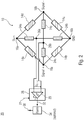
- Fig. 2 shows a schematic block diagram of an electrical circuit 20 according to another embodiment.
- the electrical circuit 20 comprises the electrical circuit 10 as described in connection with FIG Fig. 1 and a comparator 28 connected to the first tap 26a and the second tap 26b.
- the comparator 28 is designed to perform a comparison between the first voltage potential at the first tap 26a and the second voltage potential at the second tap 26b. This can be done so that a respective voltage potential at the tap 26a and the tap 26b is detected against a reference voltage, for example 0 V or ground (ground GND) and compared against each other. Alternatively, the two voltage potentials at the taps 26a and 26b can be directly compared.
- a differential voltage U DRIFT is established , which is detected by the comparison device 28.
- the voltage U DRIFT has a value of 0 V or approximately 0 V.
- the comparator 28 is configured to provide an output signal 32 indicative of an error of one of the strain gages 14a-14d of the full-bridge DMS circuit.
- the comparator may be configured to provide the output signal 32 based on the comparison of the voltage potentials to indicate an error of one of the resistors 24a-24d.
- the outputting of the output signal may be conditional, such as when the comparator has logic.
- the comparison device 28 may have a comparator 29, for example to check the fulfillment of a condition (reaching, falling below or exceeding a threshold value) of the output signal and / or to output the output signal 32 in a digitized form.
- the output signal 32 may also be a boosted, unamplified or damped version of the voltage waveform of the voltage U DRIFT .
- the comparison device 28 may have a microcontroller with at least two A / D differential transducers (not shown here), the AD differential transducers having the first tap 26a and the second tap 26b and also the signal connections 18a (signal +). and 18b (signal) are connected.
- the microcontroller also has the usual peripherals such as a CPU, a memory (RAM, ROM) for storing program code and other data, etc. With the microcontroller, the fulfillment of a condition (reaching, falling below or exceeding a threshold value) of the output signal can also be checked and / or the output signal 32 can be output in a digitized form.
- the output signal 32 may also be a boosted, unamplified or damped version of the voltage waveform of the voltage U DRIFT .
- the microcontroller can also be integrated a temperature sensor or sensor. However, it is also conceivable to connect to the microcontroller a separate and / or additional temperature sensor or sensor or temperature-dependent resistor.
- the comparator 28 is configured to provide the output signal 32 when a resistor 24a-24d or a strain gauge 14a-14d has an error.
- a fault may be, for example, a mechanical or electrical damage to a resistor 24a-24d or strain gauge 14a-14d.
- a strain gauge may also be considered defective if a substrate or material to which the strain gage 14a-14d is attached has a local deformation such that the strain gage is deformed in at least one, several, or all loading states Substrate has a different resistance from other strain gauges.
- Other failures that can be detected are faulty connection points between lines and strain gauges or resistors or age-related changes in the elements, for example due to material fatigue. Even if some of these faults are outside the strain gages or resistors, they can be detected because they affect the electrical conductivity of the circuit or its symmetry.
- the electrical circuit 20 may include an optional alarm signal generator 34 configured to receive the output signal 32 and to output an alarm signal 36.
- the alarm signal may be any signal, such as electrical or optical. Between the output of the alarm signal 36 and the output signal 32, any conditioning can be stored in the alarm signal transmitter 34.
- the alarm signal generator may be configured to output the alarm signal 36 when an amplitude, frequency or current value of the output signal 32 reaches or exceeds a threshold value.
- the output signal 32 is directly or indirectly proportional to the amplitude of the voltage U DRIFT and in the alarm signal transmitter 34 a threshold value to be reached or exceeded.
- the alarm signal generator is configured to output the alarm signal 36 when the output signal 32 is present or off, such as when the comparator 28 is configured to output the output signal 32 when an amplitude of the voltage U DRIFT reaches or exceeds the threshold.
- the alarm can also be formed as part of the comparator 26.
- the comparator 28 may be configured to receive temperature information 31.
- the temperature information may indicate a temperature at one or more resistors 24a-24d.
- the comparison device may be configured to correct a temperature-based change of a resistor or a plurality of resistors to be corrected based on the temperature information 31 with respect to a resistance value.
- the comparison device 28 can thus be designed to respect a corresponding potential at the tap 26a and / or 26b. Correct the temperature-induced change in the resistance value accordingly.
- a temperature characteristic of the resistors and / or reference resistors 24a-24d may be deposited in the comparator.
- the differential voltage of the reference bridge ie the voltage U DRIFT can be digitized by an A / D converter (analog-to-digital converter). After a temperature correction has been obtained, this (corrected) measured value can be correlated with a load state of a device on which the full-bridge DMS 12 is arranged, for example the reference state or 0 kg. Any change around 0 kg can be interpreted as a drift in kilograms, ie as a mechanical load on the full bridge DMS circuit 12, if the resistors use the same calibration factor used to calculate the actual load on the DMS bridge.
- the application of a previously stored temperature characteristic to the output signal of the two voltage dividers or resistor series circuits 22a and 22b as a function of the currently measured temperature eliminates a temperature influence on the resistors 24a / 24b and 24c / 24d.
- the temperature characteristic can be realized as a list of correction factors related to the respective temperature (so-called look-up table) or determined or determined during operation. With the application of the temperature characteristic, an always equal output voltage of the voltage dividers 22a and 22b is achieved over the entire temperature range.
- Fig. 3a shows a first state of the electrical circuit 10 with applied supply voltage.
- the first state there are an unloaded case of the full-bridge DMS circuit 12 and error-free components thereof and the two resistor series circuits.
- the voltage U BATT relative to the reference voltage GND has a voltage difference of 5V.
- any supply voltage to the strain gage full bridge circuit 12 can be applied, for example at least 0.1 V and at most 1000 V, at least 1 V and at most 100 V or at least 2.5 V and at most 20 V.
- the supply voltage U BATT drops in equal parts across the strain gauges 14a and 14b and equally over the DMS 14c and 14d from.
- Half of the supply voltage ie 2.5 V
- the supply voltage U BATT likewise drops in equal parts via the symmetrical, ie identical, resistors 24a and 24b, so that a voltage of 2.5 V is likewise present at the tap 26a.
- the drift voltage U DRIFT between the taps 26a and 26b is thus 0 V.
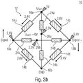
- Fig. 3b shows the electrical circuit 10 in a second case, the mechanical load on the cell, d h. the strain gauge full bridge circuit 12 describes.
- the resistance values of the strain gauges 14a and 14b or 14c and 14d can each change in opposite directions.
- the strain gauge 14a may have a reduced resistance and the strain gauge 14b may have an increased resistance value.
- a potential of 2.6 V is applied to the terminal 18a.
- a potential of 2.4 V is applied to the terminal 18b.
- This signal difference is ideally symmetrical about the average voltage of 2.5 V applied to the tap 26b.
- the resistors 24a-24d are independent of the mechanical deformation, so that the potential at the center tap 26a continues to be 2.5 V, so that the voltage U DRIFT is still 0 V. This means that in the loaded case, the auxiliary voltages can still be the same.
- the strain gages 14a-14d can change smoothly in the loaded case.
- the voltage Signal + at the terminal 18a becomes greater and the voltage Signal- at the terminal 18b becomes smaller.
- the signal voltage of the full-bridge DMS circuit 12 changes according to the difference.
- the auxiliary voltages adjust here again to 2.5 V from the equilibrium principle.
- the test voltage will remain at 0 V as in the unloaded state.
- the drift voltage U DRIFT can also be used in the loaded case of the full-bridge strain gauge circuit 12 as an indicator of the integrity of the elements.
- the comparator may be configured to provide the output independent of deformation of the strain gauges 14a-14d.
- the comparison device can be designed to make the comparison in a reference state as described in US Pat Fig. 3a is shown, and in a load state, as in Fig. 3b is shown to execute the DMS full bridge circuit 12.
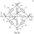
- FIG. 12 shows the electrical circuit 10 in a third state in which the strain gages 14a-14d are mechanically deformed to change their resistance as described in connection with FIG Fig. 3b is described.
- the full-bridge DMS circuit 12 has a fault condition, which in the present example is obtained by the strain gage 14a changing its resistance independently of a load condition such as damage or aging.
- the strain gauge 14a has reduced its resistance.
- a voltage of 2.4V is obtained at the terminal 18b whose DMS path is unaffected. Due to the asymmetry of the strain gauges 14a and 14b, however, another, approximately higher potential arises at the connection 18a. For example.
- the potential is still at 2.5V. Due to the changed voltage at the terminal 18a, however, the electrical potential at the tap 26b is different therefrom, so that by way of example a differential voltage U DRIFT of 0.1 V results. This can be detected by the comparator and information based thereon can be output by the output signal.
- auxiliary voltages at the taps 26a and 26b are no longer equal. Since the auxiliary voltage between the signal terminals 18a and 18b adjusts to an average of 2.6V, the difference becomes between the auxiliary voltages no longer be 0 V. This can be interpreted as a signal that the cell - independently of load - has undergone a zero-point drift.
- a threshold voltage can be adjusted via a comparator, such as the comparator 29, so that a minimum deviation (threshold) of the drift voltage U DRIFT must first be reached or exceeded, so that an output signal and / or error signal is generated.
- the comparator may be configured to output the output signal such that if the voltage potential at the tap 26a and the voltage potential at the tap 26b are equal, it indicates that there is no drift and that the voltage potentials at the taps 26a and 26b are inequality indicating that there is a drift in the electrical circuit.
- an arranged comparison device 28 may be designed to correct one or more of the signals obtained with respect to temperature-induced changes of the resistors 24a-d.
- the following consideration is used in the following, wherein the stated values are to be understood as illustrative and not restrictive.
- the full-bridge DMS circuit 12 is configured to obtain a signal change 1 mV / V at 1000 kg load on a structure where the full-bridge DMS 12 corresponds, the following scenario can be obtained with an exemplary supply voltage of 5 V of the full-bridge DMS:
- a strain gauge within the measuring bridge can change in such a way due to aging, manufacturing tolerances or damage that the measuring bridge delivers a signal change of the equivalent of 1 kg. This corresponds to a signal voltage change between signal + and signal - of 5 ⁇ V.
- the center voltage of the two reference resistors 24c and 24d between the terminals 18a and 18b will accordingly undergo a change of 2.5 ⁇ V.
- Such misinformation may result in a late or premature alarm signal or error behavior of a controller.
- resistors can often or even always be subject to temperature dependence. Not only can the amount of dependency differ, but also its direction (sign). For example, with a positive temperature change, three out of four resistors may experience an increase in resistance, and the fourth resistance may experience a decrease in resistance. Therefore, it may be useful, as stated above, to perform a comparison with one or more reference resistors, which have a predetermined or permissible temperature dependence. This temperature dependence or the range within which a resistance value of a reference resistor moves with a temperature change can be within the permissible total error limits which result for the reference resistances from tolerance, temperature dependence, etc.
- a further advantage of exemplary embodiments described above is that the function of the resistors 24a-d can also be checked and / or monitored. Should a resistor of a resistor series circuit change, for example due to production or aging technical reasons or due to damage, then the function of the electrical circuit, i. H. drift indicator, not at risk. A drift signal other than 0 V, which differs from the normal state, is nevertheless output in this case, although the cause is not in the strain gauges 14a-14d. However, this can still be understood that a review of the electrical circuit 10 is required. In terms of safety, a one-fault case for strain gages and resistors can thus be covered. Furthermore, self-monitoring of the monitoring elements, i. H. the resistors 24a-24d are obtained.
- Fig. 4 shows a schematic perspective view of a load cell 40 according to an embodiment.
- the load cell 40 includes the electrical circuit 10.
- the load cell 40 may also include the electrical circuit 20.
- the load cell 40 has a first side 42 and a second side 44, which are connectable to different mechanical components.
- one side may be connected to a base and the other side to a reference structure.
- the reference structure can it is a working platform, a weighing pan or scale level for weighing an object or the like.
- a movement of the different mechanical components to each other or a force acting on at least one of the different mechanical components and thus on at least one of the sides 42 or 44, can lead to a load on the load cell 40, to a deformation of components thereof and thus to a load the strain gauge full bridge circuit 12 lead.
- the force may alternatively or additionally also be a weight force, i. That is, based on the load cell 40, a weight load of the first side 42 relative to the second side 44 or vice versa may be detectable.
- Embodiments relate to load sensing devices.
- Load sensing devices are, for example, designed to detect a load acting on an element or device.
- One application of load sensing devices are hoisting machines designed to lift a load.
- Exemplary hoisting machines are cranes, (fork) forklifts, garbage or container vehicles or wheel loaders, this list is not exhaustive.
- Load sensing devices for hoisting machines according to embodiments described herein include, for example, a mechanism for moving a load such as a crane, a hoist or the like.
- the mechanism is attachable to a base, such as a vehicle or structure to which the load is to be moved.
- a load cell is arranged between the mechanism and the load.
- the mechanism and the load are interconnected by the load cell, so that a load of the load on the mechanism and / or from the mechanism to the load can be precisely detected.
- an electrical circuit or load cell may be connected to hoisting machines where load and / or weight sensing is desirable, such as aerial work platforms or other industrial applications, ie, devices or systems.
- a load cell is connected to vehicles such as a forklift truck, a refuse vehicle (such as a load cell for weighing a ton), a wheel loader (such as or in combination with pressure sensors on at least one hydraulic cylinder thereof)
- a vehicle has a load sensing device for a (lifting) mechanism. Between the mechanism and the load, for example, the electronic circuit or the load cell is arranged.
- Fig. 5a shows a schematic view of a load sensing device 50 for a load 52, for example.
- the load detection device 50 comprises a mechanism 54, for example a crane mechanism for moving the working platform 52, ie the working platform 52 can be realized as an aerial work platform.
- the crane mechanism 54 is attachable to a base. Between the crane mechanism 54 and the work platform 52, the load cell 40 is arranged.
- the work platform 52 and the crane mechanism 54 are interconnected by the load cell 40. That is, a mechanical connection exists between the work platform 52 and the crane mechanism 54 via the load cell 40.
- a force F for example, by their weight and / or a loading thereof, which leads to a load on the crane mechanism 54 , which is detectable via the load cell 40.
- any other (possibly external) force acting on the work platform and be detected.
- Fig. 5b shows the junction between the platform 52 and the crane mechanism 54 in an enlarged view.
- the first side 42 of the load cell is connected to the work platform 52.
- the second side 44 of the load cell is connected to the crane mechanism 54.
- angle plates or other mechanical connecting elements may be arranged to establish a mechanical connection between the working platform 52 or the crane mechanism 54 and the weighing cell.
- the location of the load cell 40 between the crane mechanism 54 and the work platform 52 enables detection of a load that the work platform 52 exerts on the crane mechanism 54, such as by a weight of the work platform 52.
- Fig. 6 shows a schematic representation of a vehicle 60, on the chassis of the load detection device 50 is arranged.
- the base of the crane mechanism 54 is attached to the vehicle chassis 62.
- the electrical circuit of the load cell 40 can in a particularly simple and reliable manner secure operation of the load sensing device 50 and the crane mechanism 54 allow as in each operating state of the crane mechanism 54, ie in a loaded state thereof or in a loaded state of the load cell 40 a Function check of the electrical circuit can be done, ie, it can be determined whether there is a drift in the DMS full bridge circuit.
- a crane mechanism can also be realized as a (construction) crane or as a crane mounted on a building and combined with a weighing cell described herein.
- a load condition of any structure may be detected or monitored.
- Embodiments described herein provide an indicator that enables detection of a disturbance or destruction of the balance of the DMS full bridge circuit and other Wheatstone bridge circuits and provides a corresponding signal regardless of load.
- Two auxiliary voltages are generated by means of the two voltage dividers in the resistor series circuits. In an ideal full bridge, the difference between these two voltages is 0 V.
- This test voltage U DRIFT is used to identify a deviation as drift. Simplified, a voltage of 0 V or nearly 0 V can be interpreted as "there is no drift before” and a voltage of greater or lesser than 0 V is interpreted as "there is a drift before”.
- the zero point drift of the cell ie the full-bridge strain gage circuit
- the zero point drift of the cell can be measured at any point in time or in any operating state, loaded or unloaded.
- the total cell drift can be computationally eliminated at any point in time or in any operating state.
- aspects have been described in the context of a device, it will be understood that these aspects also constitute a description of the corresponding method, so that a block or a component of a device is also to be understood as a corresponding method step or as a feature of a method step. Similarly, aspects described in connection with or as a method step also represent a description of a corresponding block or detail or feature of a corresponding device.
Landscapes
- Physics & Mathematics (AREA)
- General Physics & Mathematics (AREA)
- Engineering & Computer Science (AREA)
- Structural Engineering (AREA)
- Mechanical Engineering (AREA)
- Life Sciences & Earth Sciences (AREA)
- Geology (AREA)
- Business, Economics & Management (AREA)
- Emergency Management (AREA)
- Measurement Of Force In General (AREA)
Claims (12)
- Cellule de pesage (40) avec un premier côté (42) et un deuxième côté (44) présentant un circuit électrique (10; 20), dans laquelle le circuit électrique présente:un circuit en pont complet à jauges de contrainte (12);un premier circuit série de résistances (22a) connecté entre les bornes (16a, 16b) d'une porte d'alimentation du circuit en pont complet à jauges de contrainte (12) et présentant une première prise (26a) entre deux résistances (24a, 24b);un deuxième circuit série de résistances (22b) connecté entre les bornes (18a, 18b) d'une porte de signal du circuit en pont complet à jauges de contrainte (12), et présentant une deuxième prise (26b) entre deux résistances (24c, 24d);caractérisée parun moyen de comparaison (28) qui est couplé à la première prise (26a) et à la deuxième prise (26b) et qui est conçu pour effectuer une comparaison entre un premier potentiel de tension à la première prise (26a) et un deuxième potentiel de tension à la deuxième prise (26b);dans laquelle le circuit électrique est conçu pour mettre à disposition, sur base d'une charge mécanique sur le premier côté (42) sur base d'une force (F) agissant sur le deuxième côté (44), un signal à la porte de signal.
- Cellule de pesage selon la revendication 1, dans laquelle le moyen de comparaison (28) est conçu pour mettre à disposition, sur base de la comparaison, un signal de sortie (32) qui indique une erreur de l'une des jauges de contrainte (14a à d) du circuit en pont complet à jauges de contrainte (12).
- Cellule de pesage selon la revendication 1 ou 2, dans laquelle le moyen de comparaison (28) est conçu pour mettre à disposition, sur base de la comparaison, un signal de sortie (32) qui indique une erreur de l'une des résistances (24a à d) du premier (22a) ou deuxième (22b) circuit série de résistances.
- Cellule de pesage selon la revendication 2 ou 3, avec un émetteur de signal d'alarme (34) qui est conçu pour mettre à disposition, sur base du signal de sortie (32), un signal d'alarme (36).
- Cellule de pesage selon l'une des revendications 1 à 4, dans laquelle le moyen de comparaison (28) est conçu pour corriger le deuxième potentiel de tension en ce qui concerne un changement sur base de la température d'une résistance (24a à d) du premier (22a) ou du deuxième (22b) circuit série de résistances, pour recevoir une information de température (31) qui indique une température à la résistance à corriger (24a à d), et pour corriger le changement sur base de la température de la résistance (24a à d) à corriger sur base de l'information de température (31).
- Cellule de pesage selon l'une des revendications 1 à 5, dans laquelle le moyen de comparaison (28) est conçu pour fournir un signal de sortie (32) indépendamment d'une déformation des jauges de contrainte (24a à d).
- Cellule de pesage selon l'une des revendications 1 à 6, dans laquelle le moyen de comparaison (28) est conçu pour effectuer la comparaison dans un état de référence et dans un état de charge du circuit en pont complet à jauges de contrainte (12).
- Cellule de pesage selon l'une des revendications 1 à 7, dans laquelle le moyen de comparaison (28) est conçu pour mettre à disposition un signal de sortie (32) lorsqu'une valeur de la comparaison atteint ou excède une valeur de seuil.
- Cellule de pesage selon l'une des revendications 1 à 8, dans laquelle le moyen de comparaison (28) est conçu pour sortir un signal de sortie (32) de sorte qu'il soit indiqué, en cas d'égalité du premier potentiel de tension et du deuxième potentiel de tension est indiquée, qu'il n'existe pas de dérive et qu'il soit indiqué, en cas d'une inégalité du premier potentiel de tension et du deuxième potentiel de tension, qu'il existe une dérive.
- Dispositif de détection de charge (50) pour une machine de levage (52), aux caractéristiques suivantes:un mécanisme (54) destiné à déplacer une charge (52), où le mécanisme (54) peut être fixé à une base; etune cellule de pesage (40) selon l'une des revendications précédentes disposée entre le mécanisme (54) et la charge (52);dans lequel le mécanisme (54) et la charge (52) sont connectés l'un à l'autre par l'intermédiaire de la cellule de pesage (40).
- Dispositif de détection de charge (50) selon la revendication 10, dans lequel le mécanisme (54) est un mécanisme de grue, et dans lequel la charge (52) est une plate-forme de travail.
- Véhicule (60) avec un dispositif de détection de charge (50) selon la revendication 10 ou 11, dans lequel le mécanisme (54) est fixé à un châssis de véhicule.
Priority Applications (3)
| Application Number | Priority Date | Filing Date | Title |
|---|---|---|---|
| EP16155196.5A EP3205992B1 (fr) | 2016-02-11 | 2016-02-11 | Commutation electrique, cellule de pesage, dispositif de detection de charge et vehicule comprenant un dispositif de detection de charge |
| CN201710072892.XA CN107063523B (zh) | 2016-02-11 | 2017-02-10 | 电子电路、测压仪、负载检测设备以及包括其的车辆 |
| US15/430,094 US10495529B2 (en) | 2016-02-11 | 2017-02-10 | Electrical full bridge strain gauge circuit, load cell, and load detection device for use in lifting platforms, trucks, and other machines |
Applications Claiming Priority (1)
| Application Number | Priority Date | Filing Date | Title |
|---|---|---|---|
| EP16155196.5A EP3205992B1 (fr) | 2016-02-11 | 2016-02-11 | Commutation electrique, cellule de pesage, dispositif de detection de charge et vehicule comprenant un dispositif de detection de charge |
Publications (2)
| Publication Number | Publication Date |
|---|---|
| EP3205992A1 EP3205992A1 (fr) | 2017-08-16 |
| EP3205992B1 true EP3205992B1 (fr) | 2019-06-19 |
Family
ID=55353072
Family Applications (1)
| Application Number | Title | Priority Date | Filing Date |
|---|---|---|---|
| EP16155196.5A Active EP3205992B1 (fr) | 2016-02-11 | 2016-02-11 | Commutation electrique, cellule de pesage, dispositif de detection de charge et vehicule comprenant un dispositif de detection de charge |
Country Status (3)
| Country | Link |
|---|---|
| US (1) | US10495529B2 (fr) |
| EP (1) | EP3205992B1 (fr) |
| CN (1) | CN107063523B (fr) |
Families Citing this family (9)
| Publication number | Priority date | Publication date | Assignee | Title |
|---|---|---|---|---|
| EP3199486B1 (fr) * | 2016-01-28 | 2018-06-20 | MOBA - Mobile Automation AG | Mécanisme de grue et plate-forme de travail avec un dispositif de detection de charge et un capteur d'inclinaison intégré |
| CN107966193A (zh) * | 2017-11-02 | 2018-04-27 | 广东乐心医疗电子股份有限公司 | 一种可分区测量的电子秤 |
| CN108548630B (zh) * | 2018-04-05 | 2020-06-26 | 宁波依诺汽车电子有限公司 | 汽车压力传感器 |
| CN109030929B (zh) * | 2018-07-06 | 2024-05-24 | 杰华特微电子股份有限公司 | 负载插入检测电路和方法 |
| FR3087762A1 (fr) * | 2018-10-26 | 2020-05-01 | Haulotte Group | Systeme de pesage pour plate-forme de travail d’une nacelle elevatrice a mat |
| US10801882B2 (en) * | 2018-11-16 | 2020-10-13 | General Electric Company | Methods and system for obtaining a force measurement with reduced drift effects |
| US11885704B2 (en) | 2020-07-27 | 2024-01-30 | Precision Biomems Corporation | Flexible two-dimensional sheet array of electronic sensor devices |
| US11650110B2 (en) * | 2020-11-04 | 2023-05-16 | Honeywell International Inc. | Rosette piezo-resistive gauge circuit for thermally compensated measurement of full stress tensor |
| WO2022104624A1 (fr) | 2020-11-19 | 2022-05-27 | Goertek Inc. | Appareil et procédé de détection de force et dispositif électronique |
Family Cites Families (21)
| Publication number | Priority date | Publication date | Assignee | Title |
|---|---|---|---|---|
| GB693368A (en) * | 1950-06-23 | 1953-07-01 | Sangamo Weston | Improvements in or relating to electrical bridge measuring instruments employing ratiometers |
| FI47144C (fi) * | 1972-06-27 | 1973-09-10 | Datex Oy | Anturin lämpötilankompensointi. |
| US3816812A (en) * | 1973-04-19 | 1974-06-11 | G Alber | Portable apparatus for measuring load resistance |
| US4120195A (en) * | 1977-08-11 | 1978-10-17 | The United States Of America As Represented By The Secretary Of The Air Force | Method of using embedded normal stress sensors in propellant grains |
| US4541496A (en) * | 1984-03-12 | 1985-09-17 | Frazier Precision Instrument Company, Inc. | Measurement circuit for load cell mass comparator |
| AU657016B2 (en) * | 1991-12-16 | 1995-02-23 | Sharp Kabushiki Kaisha | A circuit for humidity detection |
| US5296655A (en) * | 1992-02-10 | 1994-03-22 | Beowulf Corporation | Control system for multiple input scales |
| US5369226A (en) * | 1993-04-29 | 1994-11-29 | Mettler-Toledo, Inc. | Load shift compensation for weighing apparatus |
| DE4417228A1 (de) * | 1994-05-17 | 1995-11-23 | Michael Dr Altwein | Dehnungsmeßstreifen-Meßanordnung, Verwendung derselben und Modulationsverstärker für derartige Meßanordnungen |
| JP2003034498A (ja) * | 2001-07-23 | 2003-02-07 | Hitachi Constr Mach Co Ltd | 高所作業車の過負荷検出装置 |
| DE20210958U1 (de) | 2002-07-19 | 2003-01-09 | MOBA-Mobile Automation GmbH, 65604 Elz | Lasterfassungseinrichtung |
| CN101244792B (zh) * | 2007-03-30 | 2010-08-18 | 上海港务工程公司 | 起重船起重用超载测定报警装置及其测定方法 |
| GB2450360C (en) * | 2007-06-21 | 2020-01-29 | Niftylift Ltd | Load monitoring system |
| CN100545669C (zh) * | 2007-12-11 | 2009-09-30 | 天津大学 | 逆变器运行状态显示与故障在线诊断电路 |
| GB2463915B (en) * | 2008-09-30 | 2012-06-20 | Niftylift Ltd | Load monitoring system |
| CN101813707A (zh) * | 2010-03-31 | 2010-08-25 | 中国人民解放军国防科学技术大学 | 压阻传感器的对称电桥测试系统 |
| CN202048909U (zh) * | 2010-11-03 | 2011-11-23 | 合肥工业大学 | 光照方位检测电路 |
| FR3000200B1 (fr) * | 2012-12-24 | 2016-04-15 | Haulotte Group | Mecanisme de pesee pour une nacelle et nacelle elevatrice comprenant un tel mecanisme de pesee |
| CN103234689A (zh) * | 2013-04-24 | 2013-08-07 | 武汉航空仪表有限责任公司 | 一种高精度压力变送器电路 |
| CN103575376B (zh) * | 2013-10-12 | 2017-04-05 | 酒泉钢铁(集团)有限责任公司 | 一种在线解决多只称重传感器输出信号负向漂移的电路及方法 |
| CN103557969B (zh) * | 2013-11-07 | 2016-02-24 | 南京环科电子技术有限公司 | 可精确修调温漂误差的陶瓷压力传感器芯片及修调系统和修调方法 |
-
2016
- 2016-02-11 EP EP16155196.5A patent/EP3205992B1/fr active Active
-
2017
- 2017-02-10 US US15/430,094 patent/US10495529B2/en active Active
- 2017-02-10 CN CN201710072892.XA patent/CN107063523B/zh active Active
Non-Patent Citations (1)
| Title |
|---|
| None * |
Also Published As
| Publication number | Publication date |
|---|---|
| CN107063523A (zh) | 2017-08-18 |
| CN107063523B (zh) | 2020-02-07 |
| US10495529B2 (en) | 2019-12-03 |
| EP3205992A1 (fr) | 2017-08-16 |
| US20170234747A1 (en) | 2017-08-17 |
Similar Documents
| Publication | Publication Date | Title |
|---|---|---|
| EP3205992B1 (fr) | Commutation electrique, cellule de pesage, dispositif de detection de charge et vehicule comprenant un dispositif de detection de charge | |
| DE102017201163A1 (de) | Kraft- / drehmoment-sensor, welcher eine redundante instrumentierung aufweist und betriebsbereit ist, um fehler zu erkennen | |
| EP3149439B1 (fr) | Capteur de couple et procédé pour détecter des couples s'exerçant sur une articulation d'un robot à bras articulé ou dans cette articulation | |
| EP2901100B1 (fr) | Transmetteur d'allongement | |
| DE102010007937B4 (de) | Verfahren und Vorrichtung zum selbsttätigen Kalibrieren von Dehnungs- oder Kraftaufnehmern | |
| EP3199486B1 (fr) | Mécanisme de grue et plate-forme de travail avec un dispositif de detection de charge et un capteur d'inclinaison intégré | |
| DE102015004937A1 (de) | Kraftmesssystem mit Doppelsensor | |
| EP1695048B1 (fr) | Cellule de pesage | |
| DE202016008592U1 (de) | Sensor | |
| DE102010035862B4 (de) | Diagnosefähige resistive Druckmesszelle | |
| EP3671141B1 (fr) | Cellule de pesage et pied de pesage | |
| EP2543979A2 (fr) | Transducteur de pression | |
| DE3438498C2 (fr) | ||
| DE102008001242B4 (de) | Kraftmessbolzen mit geringer Nichtlinearität und Hysterese | |
| EP3246673A1 (fr) | Cellule de charge | |
| WO2021032760A1 (fr) | Correction de valeur de mesure numérique dans un dispositif de mesure de force intégré dans une structure de connexion | |
| DE102008029055A1 (de) | Kraft- und momentenmessendes Befestigungselement | |
| EP1050748A1 (fr) | Capteur à jauges de contrainte | |
| DE102011084972B4 (de) | Verfahren zur Korrektur von Messwerten einer Druckmesszelle, deren Membran durch eine erhöhte Druckbelastung eine plastische Verformung erfahren hat | |
| DE10231447B4 (de) | Mechanisch elektrischer Wandler | |
| DE102017214171A1 (de) | Flurförderzeug mit heb- und senkbaren Lastaufnahmemitteln mit einer Belastungsmesseinrichtung | |
| CH694347A5 (de) | Vorrichtung zur Gewichtsbestimmung. | |
| DE102010012670A1 (de) | Gapelstapler mit einer Vorrichtung zur Erfassung einer Gewichtsbelastung | |
| WO2008037095A1 (fr) | Pèse-silo | |
| DE2100149C3 (de) | überlastsicherung für Auslegerkrane |
Legal Events
| Date | Code | Title | Description |
|---|---|---|---|
| PUAI | Public reference made under article 153(3) epc to a published international application that has entered the european phase |
Free format text: ORIGINAL CODE: 0009012 |
|
| STAA | Information on the status of an ep patent application or granted ep patent |
Free format text: STATUS: REQUEST FOR EXAMINATION WAS MADE |
|
| 17P | Request for examination filed |
Effective date: 20170104 |
|
| AK | Designated contracting states |
Kind code of ref document: A1 Designated state(s): AL AT BE BG CH CY CZ DE DK EE ES FI FR GB GR HR HU IE IS IT LI LT LU LV MC MK MT NL NO PL PT RO RS SE SI SK SM TR |
|
| STAA | Information on the status of an ep patent application or granted ep patent |
Free format text: STATUS: EXAMINATION IS IN PROGRESS |
|
| 17Q | First examination report despatched |
Effective date: 20171012 |
|
| GRAP | Despatch of communication of intention to grant a patent |
Free format text: ORIGINAL CODE: EPIDOSNIGR1 |
|
| STAA | Information on the status of an ep patent application or granted ep patent |
Free format text: STATUS: GRANT OF PATENT IS INTENDED |
|
| INTG | Intention to grant announced |
Effective date: 20190110 |
|
| GRAS | Grant fee paid |
Free format text: ORIGINAL CODE: EPIDOSNIGR3 |
|
| GRAA | (expected) grant |
Free format text: ORIGINAL CODE: 0009210 |
|
| STAA | Information on the status of an ep patent application or granted ep patent |
Free format text: STATUS: THE PATENT HAS BEEN GRANTED |
|
| AK | Designated contracting states |
Kind code of ref document: B1 Designated state(s): AL AT BE BG CH CY CZ DE DK EE ES FI FR GB GR HR HU IE IS IT LI LT LU LV MC MK MT NL NO PL PT RO RS SE SI SK SM TR |
|
| REG | Reference to a national code |
Ref country code: GB Ref legal event code: FG4D Free format text: NOT ENGLISH |
|
| REG | Reference to a national code |
Ref country code: CH Ref legal event code: EP |
|
| REG | Reference to a national code |
Ref country code: IE Ref legal event code: FG4D Free format text: LANGUAGE OF EP DOCUMENT: GERMAN |
|
| REG | Reference to a national code |
Ref country code: DE Ref legal event code: R096 Ref document number: 502016005101 Country of ref document: DE |
|
| REG | Reference to a national code |
Ref country code: AT Ref legal event code: REF Ref document number: 1146129 Country of ref document: AT Kind code of ref document: T Effective date: 20190715 |
|
| REG | Reference to a national code |
Ref country code: NL Ref legal event code: MP Effective date: 20190619 |
|
| PG25 | Lapsed in a contracting state [announced via postgrant information from national office to epo] |
Ref country code: SE Free format text: LAPSE BECAUSE OF FAILURE TO SUBMIT A TRANSLATION OF THE DESCRIPTION OR TO PAY THE FEE WITHIN THE PRESCRIBED TIME-LIMIT Effective date: 20190619 Ref country code: AL Free format text: LAPSE BECAUSE OF FAILURE TO SUBMIT A TRANSLATION OF THE DESCRIPTION OR TO PAY THE FEE WITHIN THE PRESCRIBED TIME-LIMIT Effective date: 20190619 Ref country code: LT Free format text: LAPSE BECAUSE OF FAILURE TO SUBMIT A TRANSLATION OF THE DESCRIPTION OR TO PAY THE FEE WITHIN THE PRESCRIBED TIME-LIMIT Effective date: 20190619 Ref country code: NO Free format text: LAPSE BECAUSE OF FAILURE TO SUBMIT A TRANSLATION OF THE DESCRIPTION OR TO PAY THE FEE WITHIN THE PRESCRIBED TIME-LIMIT Effective date: 20190919 Ref country code: HR Free format text: LAPSE BECAUSE OF FAILURE TO SUBMIT A TRANSLATION OF THE DESCRIPTION OR TO PAY THE FEE WITHIN THE PRESCRIBED TIME-LIMIT Effective date: 20190619 Ref country code: FI Free format text: LAPSE BECAUSE OF FAILURE TO SUBMIT A TRANSLATION OF THE DESCRIPTION OR TO PAY THE FEE WITHIN THE PRESCRIBED TIME-LIMIT Effective date: 20190619 |
|
| REG | Reference to a national code |
Ref country code: LT Ref legal event code: MG4D |
|
| PG25 | Lapsed in a contracting state [announced via postgrant information from national office to epo] |
Ref country code: LV Free format text: LAPSE BECAUSE OF FAILURE TO SUBMIT A TRANSLATION OF THE DESCRIPTION OR TO PAY THE FEE WITHIN THE PRESCRIBED TIME-LIMIT Effective date: 20190619 Ref country code: RS Free format text: LAPSE BECAUSE OF FAILURE TO SUBMIT A TRANSLATION OF THE DESCRIPTION OR TO PAY THE FEE WITHIN THE PRESCRIBED TIME-LIMIT Effective date: 20190619 Ref country code: BG Free format text: LAPSE BECAUSE OF FAILURE TO SUBMIT A TRANSLATION OF THE DESCRIPTION OR TO PAY THE FEE WITHIN THE PRESCRIBED TIME-LIMIT Effective date: 20190919 Ref country code: GR Free format text: LAPSE BECAUSE OF FAILURE TO SUBMIT A TRANSLATION OF THE DESCRIPTION OR TO PAY THE FEE WITHIN THE PRESCRIBED TIME-LIMIT Effective date: 20190920 |
|
| PG25 | Lapsed in a contracting state [announced via postgrant information from national office to epo] |
Ref country code: EE Free format text: LAPSE BECAUSE OF FAILURE TO SUBMIT A TRANSLATION OF THE DESCRIPTION OR TO PAY THE FEE WITHIN THE PRESCRIBED TIME-LIMIT Effective date: 20190619 Ref country code: PT Free format text: LAPSE BECAUSE OF FAILURE TO SUBMIT A TRANSLATION OF THE DESCRIPTION OR TO PAY THE FEE WITHIN THE PRESCRIBED TIME-LIMIT Effective date: 20191021 Ref country code: SK Free format text: LAPSE BECAUSE OF FAILURE TO SUBMIT A TRANSLATION OF THE DESCRIPTION OR TO PAY THE FEE WITHIN THE PRESCRIBED TIME-LIMIT Effective date: 20190619 Ref country code: CZ Free format text: LAPSE BECAUSE OF FAILURE TO SUBMIT A TRANSLATION OF THE DESCRIPTION OR TO PAY THE FEE WITHIN THE PRESCRIBED TIME-LIMIT Effective date: 20190619 Ref country code: RO Free format text: LAPSE BECAUSE OF FAILURE TO SUBMIT A TRANSLATION OF THE DESCRIPTION OR TO PAY THE FEE WITHIN THE PRESCRIBED TIME-LIMIT Effective date: 20190619 Ref country code: NL Free format text: LAPSE BECAUSE OF FAILURE TO SUBMIT A TRANSLATION OF THE DESCRIPTION OR TO PAY THE FEE WITHIN THE PRESCRIBED TIME-LIMIT Effective date: 20190619 |
|
| PG25 | Lapsed in a contracting state [announced via postgrant information from national office to epo] |
Ref country code: ES Free format text: LAPSE BECAUSE OF FAILURE TO SUBMIT A TRANSLATION OF THE DESCRIPTION OR TO PAY THE FEE WITHIN THE PRESCRIBED TIME-LIMIT Effective date: 20190619 Ref country code: SM Free format text: LAPSE BECAUSE OF FAILURE TO SUBMIT A TRANSLATION OF THE DESCRIPTION OR TO PAY THE FEE WITHIN THE PRESCRIBED TIME-LIMIT Effective date: 20190619 Ref country code: IS Free format text: LAPSE BECAUSE OF FAILURE TO SUBMIT A TRANSLATION OF THE DESCRIPTION OR TO PAY THE FEE WITHIN THE PRESCRIBED TIME-LIMIT Effective date: 20191019 |
|
| PG25 | Lapsed in a contracting state [announced via postgrant information from national office to epo] |
Ref country code: TR Free format text: LAPSE BECAUSE OF FAILURE TO SUBMIT A TRANSLATION OF THE DESCRIPTION OR TO PAY THE FEE WITHIN THE PRESCRIBED TIME-LIMIT Effective date: 20190619 |
|
| PG25 | Lapsed in a contracting state [announced via postgrant information from national office to epo] |
Ref country code: PL Free format text: LAPSE BECAUSE OF FAILURE TO SUBMIT A TRANSLATION OF THE DESCRIPTION OR TO PAY THE FEE WITHIN THE PRESCRIBED TIME-LIMIT Effective date: 20190619 Ref country code: DK Free format text: LAPSE BECAUSE OF FAILURE TO SUBMIT A TRANSLATION OF THE DESCRIPTION OR TO PAY THE FEE WITHIN THE PRESCRIBED TIME-LIMIT Effective date: 20190619 |
|
| PG25 | Lapsed in a contracting state [announced via postgrant information from national office to epo] |
Ref country code: IS Free format text: LAPSE BECAUSE OF FAILURE TO SUBMIT A TRANSLATION OF THE DESCRIPTION OR TO PAY THE FEE WITHIN THE PRESCRIBED TIME-LIMIT Effective date: 20200224 |
|
| REG | Reference to a national code |
Ref country code: DE Ref legal event code: R097 Ref document number: 502016005101 Country of ref document: DE |
|
| PLBE | No opposition filed within time limit |
Free format text: ORIGINAL CODE: 0009261 |
|
| STAA | Information on the status of an ep patent application or granted ep patent |
Free format text: STATUS: NO OPPOSITION FILED WITHIN TIME LIMIT |
|
| PG2D | Information on lapse in contracting state deleted |
Ref country code: IS |
|
| 26N | No opposition filed |
Effective date: 20200603 |
|
| PG25 | Lapsed in a contracting state [announced via postgrant information from national office to epo] |
Ref country code: SI Free format text: LAPSE BECAUSE OF FAILURE TO SUBMIT A TRANSLATION OF THE DESCRIPTION OR TO PAY THE FEE WITHIN THE PRESCRIBED TIME-LIMIT Effective date: 20190619 |
|
| REG | Reference to a national code |
Ref country code: CH Ref legal event code: PL |
|
| REG | Reference to a national code |
Ref country code: BE Ref legal event code: MM Effective date: 20200229 |
|
| PG25 | Lapsed in a contracting state [announced via postgrant information from national office to epo] |
Ref country code: LU Free format text: LAPSE BECAUSE OF NON-PAYMENT OF DUE FEES Effective date: 20200211 Ref country code: MC Free format text: LAPSE BECAUSE OF FAILURE TO SUBMIT A TRANSLATION OF THE DESCRIPTION OR TO PAY THE FEE WITHIN THE PRESCRIBED TIME-LIMIT Effective date: 20190619 |
|
| PG25 | Lapsed in a contracting state [announced via postgrant information from national office to epo] |
Ref country code: LI Free format text: LAPSE BECAUSE OF NON-PAYMENT OF DUE FEES Effective date: 20200229 Ref country code: CH Free format text: LAPSE BECAUSE OF NON-PAYMENT OF DUE FEES Effective date: 20200229 |
|
| PG25 | Lapsed in a contracting state [announced via postgrant information from national office to epo] |
Ref country code: IE Free format text: LAPSE BECAUSE OF NON-PAYMENT OF DUE FEES Effective date: 20200211 |
|
| PG25 | Lapsed in a contracting state [announced via postgrant information from national office to epo] |
Ref country code: BE Free format text: LAPSE BECAUSE OF NON-PAYMENT OF DUE FEES Effective date: 20200229 |
|
| REG | Reference to a national code |
Ref country code: AT Ref legal event code: MM01 Ref document number: 1146129 Country of ref document: AT Kind code of ref document: T Effective date: 20210211 |
|
| PG25 | Lapsed in a contracting state [announced via postgrant information from national office to epo] |
Ref country code: AT Free format text: LAPSE BECAUSE OF NON-PAYMENT OF DUE FEES Effective date: 20210211 |
|
| PG25 | Lapsed in a contracting state [announced via postgrant information from national office to epo] |
Ref country code: MT Free format text: LAPSE BECAUSE OF FAILURE TO SUBMIT A TRANSLATION OF THE DESCRIPTION OR TO PAY THE FEE WITHIN THE PRESCRIBED TIME-LIMIT Effective date: 20190619 Ref country code: CY Free format text: LAPSE BECAUSE OF FAILURE TO SUBMIT A TRANSLATION OF THE DESCRIPTION OR TO PAY THE FEE WITHIN THE PRESCRIBED TIME-LIMIT Effective date: 20190619 |
|
| PG25 | Lapsed in a contracting state [announced via postgrant information from national office to epo] |
Ref country code: MK Free format text: LAPSE BECAUSE OF FAILURE TO SUBMIT A TRANSLATION OF THE DESCRIPTION OR TO PAY THE FEE WITHIN THE PRESCRIBED TIME-LIMIT Effective date: 20190619 |
|
| P01 | Opt-out of the competence of the unified patent court (upc) registered |
Effective date: 20230523 |
|
| PGFP | Annual fee paid to national office [announced via postgrant information from national office to epo] |
Ref country code: DE Payment date: 20240119 Year of fee payment: 9 Ref country code: GB Payment date: 20240221 Year of fee payment: 9 |
|
| PGFP | Annual fee paid to national office [announced via postgrant information from national office to epo] |
Ref country code: IT Payment date: 20240227 Year of fee payment: 9 Ref country code: FR Payment date: 20240227 Year of fee payment: 9 |