EP2452839A1 - Bracket fixture - Google Patents
Bracket fixture Download PDFInfo
- Publication number
- EP2452839A1 EP2452839A1 EP11189371A EP11189371A EP2452839A1 EP 2452839 A1 EP2452839 A1 EP 2452839A1 EP 11189371 A EP11189371 A EP 11189371A EP 11189371 A EP11189371 A EP 11189371A EP 2452839 A1 EP2452839 A1 EP 2452839A1
- Authority
- EP
- European Patent Office
- Prior art keywords
- load
- sensors
- carrier device
- support
- evaluation unit
- Prior art date
- Legal status (The legal status is an assumption and is not a legal conclusion. Google has not performed a legal analysis and makes no representation as to the accuracy of the status listed.)
- Granted
Links
- 238000011156 evaluation Methods 0.000 claims abstract description 45
- 238000001514 detection method Methods 0.000 claims abstract description 40
- 230000001133 acceleration Effects 0.000 claims description 31
- 239000000463 material Substances 0.000 claims description 2
- 238000009434 installation Methods 0.000 abstract 2
- 230000008878 coupling Effects 0.000 description 24
- 238000010168 coupling process Methods 0.000 description 24
- 238000005859 coupling reaction Methods 0.000 description 24
- 238000005259 measurement Methods 0.000 description 14
- 230000005484 gravity Effects 0.000 description 4
- 230000001419 dependent effect Effects 0.000 description 3
- 230000000694 effects Effects 0.000 description 3
- 230000002349 favourable effect Effects 0.000 description 2
- 230000003068 static effect Effects 0.000 description 2
- 230000001960 triggered effect Effects 0.000 description 2
- 239000000853 adhesive Substances 0.000 description 1
- 230000001070 adhesive effect Effects 0.000 description 1
- 230000005540 biological transmission Effects 0.000 description 1
- 238000011088 calibration curve Methods 0.000 description 1
- 238000010586 diagram Methods 0.000 description 1
- 238000005516 engineering process Methods 0.000 description 1
Images


Classifications
-
- B—PERFORMING OPERATIONS; TRANSPORTING
- B60—VEHICLES IN GENERAL
- B60D—VEHICLE CONNECTIONS
- B60D1/00—Traction couplings; Hitches; Draw-gear; Towing devices
- B60D1/01—Traction couplings or hitches characterised by their type
-
- B—PERFORMING OPERATIONS; TRANSPORTING
- B60—VEHICLES IN GENERAL
- B60D—VEHICLE CONNECTIONS
- B60D1/00—Traction couplings; Hitches; Draw-gear; Towing devices
- B60D1/24—Traction couplings; Hitches; Draw-gear; Towing devices characterised by arrangements for particular functions
- B60D1/248—Traction couplings; Hitches; Draw-gear; Towing devices characterised by arrangements for particular functions for measuring, indicating or displaying the weight
-
- B—PERFORMING OPERATIONS; TRANSPORTING
- B60—VEHICLES IN GENERAL
- B60D—VEHICLE CONNECTIONS
- B60D1/00—Traction couplings; Hitches; Draw-gear; Towing devices
- B60D1/58—Auxiliary devices
-
- B—PERFORMING OPERATIONS; TRANSPORTING
- B60—VEHICLES IN GENERAL
- B60D—VEHICLE CONNECTIONS
- B60D1/00—Traction couplings; Hitches; Draw-gear; Towing devices
- B60D1/58—Auxiliary devices
- B60D1/62—Auxiliary devices involving supply lines, electric circuits, or the like
Definitions
- the invention relates to a support device for motor vehicles, which is designed to receive loads.
- the invention is therefore based on the object to improve a support device for motor vehicles of the type described above in such a way that the loads acting on these can be detected.
- a support device of the type described above that the support device is provided at least at a first mounting location with a first sensor and at a second mounting location with a second sensor that between the mounting locations a portion of the support device is the load-related Deformations are at least partially detected by the sensors and that an evaluation unit is provided which detects measured values of the sensors and determines a recorded load on these.
- the advantage of the solution according to the invention is the fact that with this a simple way was created to detect the recorded load, without a great expenditure on equipment must be driven.
- the portion of the support device is a one-piece section.
- portion of the support device comprises parts joined together by play-free connections.
- Such play-free connected parts can be interconnected parts, for example, by positive engagement or frictional connection, the connection must be designed without play.
- the play-free connections are integral connections.
- Such cohesive connections are, for example, adhesive joints, soldered or welded joints.
- the load-related deformations are detected in relation to detection planes of the sensors that are substantially parallel to one another.
- Essentially parallel detection planes are to be understood as detection planes that run either parallel to one another or enclose an angle of maximum plus / minus 10 ° with each other, since such small angles between the detection planes have a slight effect on the results.
- the detection levels could theoretically be chosen arbitrarily.
- the detection planes run essentially parallel to measuring directions of the sensors predetermined by a structure of the sensors, in particular to planes that are essentially parallel to planes spanned by two measuring directions of the sensors.
- the essentially parallel course of the detection plane relative to the respective plane spanned by the measurement directions is understood to mean either a parallel course or a course at an angle of at most plus / minus 10 °.
- the projection of the measurement directions lying in the one detection plane from one of the sensors to the other detection plane of the other of the sensors likewise results in a substantially parallel course of the measurement directions relative to one another, that is to say that the measurement directions in the respective plane also at most an angle of plus / minus 10 ° with each other or run parallel to each other.
- a particularly simple type of evaluation provides that the evaluation unit determines differential values from the measured values for determining the recorded load.
- the evaluation unit compares load-free difference values with load-related difference values for the purpose of evaluation.
- Such a comparison could also be made by comparing the load-dependent difference values with load-free difference values which are stored in value tables.
- a particularly favorable solution provides that the evaluation unit determines a measure of the recorded load from the deviation of the load-dependent difference values from a load-free differential value.
- the sensors could be designed to detect relative movement to one another.
- Such inclination sensors could be constructed and designed as special inclination sensors.
- the first sensor and the second sensor are acceleration sensors which can be operated as tilt sensors.
- acceleration sensors which can also be operated as tilt sensors, have the great advantage that they open up the possibility of not only detecting inclinations, but also allowing the detection of accelerations simultaneously or at different times.
- sensors that operate as inclination sensors are designed such that they detect inclinations about at least one inclination axis.
- the sensors detect inclination values with respect to a direction of gravity as a reference, so that it is possible to detect the inclination in different directions relative to the direction of gravity.
- the load-related deformations are detected by inclination difference values which are formed from inclination values of the sensors recorded as measured values.
- the deviation of the support load-related inclination difference value of the sensors from a support load-free inclination difference value can be determined by the evaluation unit.
- the sensors are aligned in such a way that an inclination value can be detected with the first sensor and the second sensor about inclination axes extending essentially parallel to one another.
- the evaluation unit detects a difference in inclination between an inclination of the first sensor about a first inclination axis and an inclination of the second sensor about a second inclination axis, and when the tilt axes are substantially perpendicular to a vehicle longitudinal center plane.
- a substantially vertical progression of the inclination axes relative to the vehicle longitudinal center plane is to be understood as meaning that the inclination axes with the vehicle longitudinal center plane enclose at least an angle of 80 °.
- the evaluation unit determines the load-free tilt difference value within the scope of a reference value measurement.
- a reference measurement can be triggered manually by pressing a key.
- Such a reference measurement can be triggered by certain operating states of the motor vehicle, for example a movement of the trailer coupling into its working position, ie, for example, mounting in the working position or moving from a rest position into the working position. or in the case of an existing trailer detection also by unlocking the same and / or starting the engine if the trailer detection does not recognize a trailer.
- the evaluation unit determines the load-related inclination difference value when the motor vehicle is not moving, so that the vehicle dynamics can not affect the support load-related inclination difference value.
- Non-moving vehicle Under a non-moving vehicle is a stationary and / or a vehicle to understand that moves at less than 5 km / h.
- the evaluation unit evaluates the admissibility of the load by comparison with a reference value predetermined in the evaluation unit, which is stored, for example or multiple signals to convey the admissibility to other units.
- the evaluation unit is coupled to a display unit which indicates the permissibility or inadmissibility of the load, for example by colored light signals, or a display bar with controllable variable coloration.
- the solution according to the invention also provides the possibility that the evaluation unit detects accelerations with at least one of the sensors.
- the evaluation unit detects accelerations with both sensors.
- the detection of accelerations with the first and second sensors opens up the possibility of also detecting dynamic forces, that is to say in the driving operation of the vehicle occurring forces.
- the evaluation unit it is possible for the evaluation unit to detect accelerations transversely to a vehicle longitudinal center plane.
- accelerations in the vehicle longitudinal center plane may be accelerations acting in a horizontal direction in particular and / or accelerations acting in a vertical direction.
- the acceleration measurements can be carried out as direct acceleration measurements with the two sensors.
- a roof rack as a carrier device.
- the carrier device comprises a body connection carrier arranged at the rear on the body and a support load receiving element held by a body joint carrier.
- Such a body joint support for example, be a cross member with side beams, the rear side of the body is mounted, the cross member is covered for example by a bumper and the side support in a lower region of the body and are connected thereto.
- the support load receiving element may also be formed in various ways.
- the support load receiving element is designed as a ball neck with a coupling device, for example with a coupling ball, to which a trailer can be attached to pull this trailer to the motor vehicle.
- the support load receiving element is formed for example as a rear load carrier, which serves to transport additional loads on the rear side with the motor vehicle.
- Such a rear load carrier may be, for example, a rear luggage carrier or a rear aggregate carrier or a rear bicycle carrier.
- first and the second mounting location are arranged on the support load receiving element.
- the first mounting location is provided on the body joint support and the second mounting location on the support load receiving element when they are to be releasably or movably connected to each other, as through this connection an undefined game between the two can occur, which would distort the measurements ,
- the motor vehicle designated as a whole by 10 comprises a vehicle body 12, on which a carrier device 20 according to the invention is mounted in a rear region 14, which has a cross member 22 covered by a bumper unit 16 and a side carrier 24 extending along the body wall sections in the longitudinal direction of the body wall , which together with the cross member form a body joint support 26, which is partially covered by the vehicle body 12 and partly by the bumper unit 16.
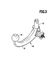
- On the body joint support 26 is designated as a whole with 30 receptacle for a in Fig. 3 shown enlarged holding member 32 of a designated as a whole with 40 supporting load receiving element, which is formed in this case as a ball neck 42, on the one hand carries the support member 32 and on the other hand provided with a coupling ball 44.
- the support load corresponding force SL which is preferably directed in the vertical direction transverse to a roadway 46 and in the direction of gravity or opposite to the direction of gravity on the coupling ball 44 can act.
- the vertical load is a measure of how much a trailer presses on the coupling ball 44 or how heavy a on the coupling ball 44 attacking rear load carrier of the motor vehicle.
- a vertical force Vo lying in a vehicle longitudinal midplane FL acts from above and / or a vertical force Vu lying in the vehicle longitudinal midplane FL from below, depending on which driving dynamic condition the motor vehicle 10 and a trailer attached to it are or a rear load carrier mounted on it.
- the coupling ball 44 acts on a substantially horizontally acting on this lateral force Ql from the left and / or an optionally opposite transverse force Qr from the right, these transverse forces Ql and Qr are preferably perpendicular to the vehicle longitudinal center plane FL.
- the coupling ball 44 is still a horizontally oriented longitudinal force Lv forward and / or a horizontally oriented longitudinal force Lr to the rear, wherein the longitudinal forces Lv and Lr are in the vehicle longitudinal center plane FL, in the same way as the vertical force from above Vo and the vertical Force from below Vu.
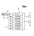
- the inventive task namely to make the driving conditions of the motor vehicle 10 safer and possibly to prevent unsafe driving conditions is achieved in the carrier device 20 according to the invention characterized in that one or more of the forces SL, Ql, Qr, Vo, Vu, Lv and Lr by a detected on the vehicle evaluation unit 50 detected and evaluated, for example, with the aid of thresholds.
- the evaluation unit 50 determines whether information signals are output for the operator of the motor vehicle or for a driving state control of the motor vehicle ( Fig. 4 ).
- the detection of the aforementioned forces by the evaluation unit 50 takes place, such as in Fig. 2 represented by two sensors S1 and S2, which are arranged at mounting locations M1 and M2 at a distance from each other on the carrier device 20 according to the invention.
- Each of the sensors S1 and S2 is a microelectromechanical system constructed in MEMS technology, which can be used both as an acceleration sensor and as a tilt sensor, for example.
- a sensor S is formed as an approximately cuboid block and capable of, in one spatial direction and / or in two spatial directions and / or in three spatial directions, for example the Spaces X, Y and Z to measure accelerations and also able to detect in the XZ plane inclinations about the Y axis as a rotation axis and in the YZ plane inclinations about the X axis as a rotation axis, if one of them assuming that the Z-axis includes the smallest angle with a vertical V, that is approximately parallel to this.
- the sensors S1 and S2 are arranged so that they are at least in the tilt detection planes E1 and E2, these are, for example, the XZ planes according to Fig. 5 , Inclinations about the Y-axis detect as a tilt axis, the planes E1 and E2 to each other preferably parallel, at most at an angle of +/- 10 °.
- the planes E1 and E2 are aligned so that the respective Y-axes transverse to the vehicle longitudinal center plane FL, preferably substantially perpendicular to the vehicle longitudinal center plane FL, wherein a substantially vertical course is to be understood that the smallest angle between the Y-axis and the vehicle longitudinal center plane FL is greater than 80 °.
- the planes E1 and E2 extend at an angle in the range between, for example, 20 ° and 60 °, wherein the alignment of the planes E1 and E2 is expediently carried out depending on the course of deformation of the section A, namely such that the deformation in the planes E1 and E2 leads to the greatest possible difference in inclination when the force SL occurs.
- the sensors S1 and S2 are aligned with their X-axes and Z-axes, which are respectively in the tilt detection planes E1 and E2, so relative to each other that a projection of the X and Z axes of the one sensor S1, S2 on the plane E2, E1 of the respective other sensor S2, S1 gives an angle between the X and Z axes of less than 10 °, wherein preferably the respective projections of the X-axes and Z-axes in the respective tilt detection planes E2, E1 are parallel to the X-axes and Z-axes lying in these tilt detection planes E2, E1.
- the inclinations to the Z-axis can be detected with a uniaxial acceleration sensor whose measuring axis is parallel to the tilt detection planes E1, E2.
- the total deformation in this section A results in that a difference value D o of the tilt values N1 or N2 detected between the sensors S1 and S2 in the tilt detection planes E1 and E2 before the application of the load SL corresponding force to the coupling ball 44 from the difference value D sl of the inclination values N1 or N2 deviates from the effect of the force SL corresponding to the vertical load on the coupling ball 44.
- This deviation between the difference values D o and D sl makes it possible to detect the deformation of section A caused by the force SL corresponding to the support load, and this deformation is dependent on, preferably approximately proportional to, the support load on the coupling ball 44 in a first approximation.
- the deviation of the difference value D sl which is detected after the action of the support load corresponding force SL on the coupling ball 44, from the difference value D o , which is detected before the action of the support load corresponding force SL on the coupling ball 44, for example in the context of Reference measurement when the hitch is moved to the working position, can thus be used by the evaluation unit 50 as a measure of the vertical load or the force SL and, if suitably calibrated, the evaluation unit 50 can either display and / or display the value of the vertical load or the force SL itself. whether the vertical load or the corresponding force SL is in a tolerable range for this motor vehicle 10 or outside a tolerable for this motor vehicle 10 range of values.
- the evaluation unit 50 is associated with a display unit 60 which displays in the form of a bar 62 the force corresponding to the vertical load SL, wherein the support load or the force SL indicating bar 62 is parallel to a scale field 64, either between a tolerable Range and a non-tolerable range or between several graded areas of tolerance differentiated or possibly even has a scale on which the values for the vertical load SL are readable.
- a display unit 60 which displays in the form of a bar 62 the force corresponding to the vertical load SL, wherein the support load or the force SL indicating bar 62 is parallel to a scale field 64, either between a tolerable Range and a non-tolerable range or between several graded areas of tolerance differentiated or possibly even has a scale on which the values for the vertical load SL are readable.
- the sensors S1 and S2 can also function as acceleration sensors and, for example, in the dynamic case, that is, when the motor vehicle 10 is moving, detect part or all of the accelerations caused by the forces Vo or Vu, Ql or Qr or Lv or Lr, as the case may be in how many axes accelerations can be detected, wherein either both sensors S1 and S2 experience the same accelerations or possibly different accelerations, for example, caused by additionally occurring deformations of the section A of the body joint carrier 26th
- the accelerations measured by the sensor S2 in these directions may be greater than the accelerations measured by the sensor S1, since the portion A of the body joint 26 in these directions is relatively large Elasticity and thus deformation may have, for example, while the transverse forces Ql or Qr generate substantially identical accelerations in the sensors S1 and S2, since in these directions, the portion A has low elasticity and thus a small deformation.
- the accelerations which are measured with the sensor S2 be greater than the acceleration, as measured by the sensor S1, since in these directions, the portion A has an elasticity that to a Deformation of the body joint carrier 26 in the region of section A lead.
- the forces corresponding to these accelerations can be determined and output by the evaluation unit 50, for example to a unit 70 which detects a dynamic load of the carrier device 20 and for example records them with respect to a time axis and / or averages over a period of time and / or for influencing vehicle dynamics control of the motor vehicle.
- the sensors S1 and S2 are arranged at equal distances from the side beams 24 and aligned so that they detect inclinations about the X-axis, ie in the YZ planes, so that the tilt detection planes E3 and E4 transversely, preferably perpendicular to the vehicle longitudinal center plane FL , wherein the Z-direction includes at least the smallest angle with the vertical V, preferably approximately parallel to the vertical V is aligned.
- the sensors S1 and S2 detect in such an arrangement, the deflection of the portion of the cross member 22 between the mounting types M1 and M2 downwards, which occurs at the force SL on the ball head 44.
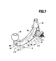
- a carrier device 20 is in a third embodiment of a carrier device 20 according to the invention, of which in Fig. 7 only the support load receiving element 40 'is shown, provided that the sensors S1 and S2 are arranged directly on the ball neck 42, wherein the sensor S1 is disposed near the holding member 32, while the sensor S2 is disposed near the coupling ball 44, so that a section A the ball neck 42 between them.
- the sensors S1 and S2 are arranged so that their tilt detection planes E'1 and E'2 are substantially parallel to each other, and these tilt detection planes E'1 and E'2 may be, for example, the XZ planes of the two sensors S1 and S2.
- the detection of the support load corresponding force SL is carried out in the same manner as described in connection with the first embodiment, by the deviation of the difference value Dsl between the detected by the sensors S1 and S2 in the tilt detection planes E'1 and E'2 inclinations of the difference value D o the inclinations detected in the unloaded state by the sensors S1 and S2 in the tilt detection planes E'1 and E'2.
- the evaluation and transmission can be carried out in a similar manner, wherein the section A 'of the ball neck 42 has a different elastic behavior than the body joint support 26, so that the display of the support load takes place taking into account a different calibration curve for the evaluation unit 50.
- the parts not expressly mentioned in connection with the third embodiment are formed in the same manner as the corresponding parts of the first embodiment, so that with respect to the description of the same fully incorporated by reference to the comments on the first embodiment.
- the body joint support 26 is formed except for the receptacle 30 "in the same manner as in the first and second embodiments and also fixed in the same manner to the rear portion 14 of the vehicle body 12 of the motor vehicle 10.
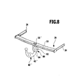
- the receptacle 30 comprises a pivot bearing 80 for the support load receiving element 40 ", wherein the pivot bearing 80 has a vehicle-fixed bearing body 82 relative to which a pivotable bearing body 84 is movably mounted, wherein the pivotable bearing body 84, for example, about a single pivot axis may be formed pivotable, such as in the patents EP 0 799 732 A and EP 1 142 732 A described, or multi-axis, in the extreme case, three-axis, can be pivoted.
- the pivot bearing 80 is further locked with a not shown in detail, preferably in the pivot bearing 80 integrated locking device 90 in at least one pivotal position, for example, in the in Fig. 8 shown working position to fix the support load receiving element 40 "relative to the body joint support 26 in a defined position as rigid as possible.
- only the sensors S1 and S2 may be arranged on the body joint support 26 as described in connection with the first embodiment.
- the sensors S1 and S2 are arranged on the ball neck 42 ", likewise such that a portion A" of the ball neck 42 "extends between the sensors S1 and S2.
- the sensors S1 and S2 are preferably arranged in recessed regions 94 and 96 relative to a lateral contour 92 of the ball neck 42 ', so that the sensors S1 and S2 are thereby protected against damage due to the lateral contour 92.
- the sensors S1 and S2 are arranged so as to be capable of detecting movements, particularly inclinations, in the tilt detection planes E'1 and E'2 in the same manner as described in the third embodiment was, with the action of one of the support load corresponding force SL on the coupling ball 44 is a deformation of the section A "of the ball neck 42", which is a measure of the support load corresponding force SL to the coupling ball 44 and in deviation of a difference value Dsl inclinations of the difference value measured by the sensors S1 and S2 when the force SL is applied in the tilt detection planes E'1 and E'2 D o shows the inclinations measured without support load from the sensors S1 and S2 in the tilt detection planes E'1 and E'2.
- FIG. 10 In a fifth embodiment of a carrier device according to the invention, shown in FIG Fig. 10 is also the body joint support 26 "'a cross member 22''is provided, which is held between side beams 24'', wherein the side support 24''do not extend along retaining walls of the rear portion 14 of the body 12, but have mounting flanges 28, which at corresponding Shooting the body 14 are screwed.
- the sensors S1 and S2 are arranged in the same way as in the first embodiment on the cross member 22 '", and detect a torsion of the portion A"' of the cross member 22 "'in the same manner as described in connection with the first embodiment has been.
- the receptacle 30 " is designed as a receiving sleeve with a square receptacle, in which a in Fig. 11 illustrated holding element 32 "', for example, designed as a square tube, can be inserted and fixed, wherein the holding element 32'" part of a designated as a whole with 40 "support load receiving element with a support load carrier 102, on whose the holding element 32 '' opposite end 34 '' one Coupling ball or another load-receiving element is mounted.
- the second sensor S2 is not arranged on the cross member 22, but on the receptacle 30 "', which is spaced from the cross member 22"', but rigidly connected thereto by means of holding bodies 36, so that the section A "" between the sensor S1 and the sensor S2 comprises a part of the cross member 22 "'and the holding body 36, which are deformed upon the action of a force corresponding to the vertical load SL and thus lead to different, measured by the sensors S1 and S2 inclination difference values D sl and D o , which can be evaluated in the same way as described in connection with the first embodiment.
- a seventh embodiment of a carrier device according to the invention shown in FIG Fig. 13 the sensors S1 and S2 are arranged on the receptacle 30 "'and thus serve to detect deformations of the receptacle 30"' due to the action of the support load, in which case the section A "" the distance through which between the sensors S1 and S2 extending portion of the receptacle 30 "'are formed.
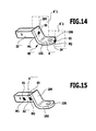
- FIG Fig. 14 it is conceivable to provide the sensors S1 and S2 on the support load receiving element 40 "', wherein, for example, the sensor S1 is arranged on an end 104 of a support load carrier 102 adjoining the holding element 32", at which end 104 the sensor S2 is arranged is.
- both sensors S1 and S2 detect at least movements in the tilt detection planes E'1 and E'2 that run essentially parallel to the vehicle longitudinal center plane FL, the evaluation of the sensor signals being carried out in the same way as described in connection with the first and second exemplary embodiments.
- the sensors S1 and S2 are once arranged on the holding element 32 "'and once at the end 104 of the support load carrier 102nd
- the sensors S1 and S2 are arranged once on the holding element 32 "'and once near the end 104 on the supporting load carrier 102.
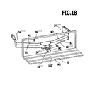
- FIG. 18 In a twelfth embodiment of a carrier device according to the invention, shown in FIG Fig. 18 is the support member 32 '' associated support load carrier 102 'designed as a rear load carrier, the rear load carrier, for example, serves to accommodate bicycles and with the held on this holding element 32'"in the receptacle 30"'is plugged to the rear load carrier 102 "on the body joint support 26 "" to fix, wherein the body joint support 26 "" in turn a cross member 22 "", which in turn is connectable with side beams 24 "" with the body of the motor vehicle.
- the rear load carrier for example, serves to accommodate bicycles and with the held on this holding element 32'"in the receptacle 30"'is plugged to the rear load carrier 102 "on the body joint support 26 "" to fix, wherein the body joint support 26 "" in turn a cross member 22 "", which in turn is connectable with side beams 24 "" with the body of the motor vehicle.
- the sensors S1 and S2 are arranged on the mounting types M1 and M2 according to the mounting modes of the second embodiment Fig. 6 correspond. But it is also conceivable that To arrange sensors S1 and S2 at all the locations which have been explained in connection with the first and fourth to tenth embodiments and the evaluation unit 50 to form accordingly.
Abstract
Description
Die Erfindung betrifft eine Trägervorrichtung für Kraftfahrzeuge, welche zur Aufnahme von Lasten ausgebildet ist.The invention relates to a support device for motor vehicles, which is designed to receive loads.
Bei derartigen Trägervorrichtungen besteht das Problem, die aufgenommenen Lasten zu erfassen, um damit beispielsweise einem Fahrer anzeigen zu können, ob die Lasten zu groß oder zu klein (d.h. negativ) sind oder noch in einem tolerablen Bereich liegen.In such carrier devices, there is the problem of detecting the loads taken in order to be able to indicate to a driver, for example, whether the loads are too large or too small (i.e., negative) or are still within a tolerable range.
Der Erfindung liegt daher die Aufgabe zugrunde, eine Trägervorrichtung für Kraftfahrzeuge der eingangs beschriebenen Art dahingehend zu verbessern, dass die auf diese einwirkenden Lasten erfasst werden können.The invention is therefore based on the object to improve a support device for motor vehicles of the type described above in such a way that the loads acting on these can be detected.
Diese Aufgabe wird bei einer Trägervorrichtung der eingangs beschriebenen Art erfindungsgemäß dadurch gelöst, dass die Trägervorrichtung mindestens an einem ersten Montageort mit einem ersten Sensor und an einem zweiten Montageort mit einem zweiten Sensor versehen ist, dass zwischen den Montageorten ein Abschnitt der Trägervorrichtung liegt, dessen lastbedingte Deformationen zumindest zum Teil durch die Sensoren erfasst werden und dass eine Auswerteeinheit vorgesehen ist, welche Messwerte der Sensoren erfasst und auf diesen eine aufgenommene Last ermittelt.This object is achieved in a support device of the type described above according to the invention that the support device is provided at least at a first mounting location with a first sensor and at a second mounting location with a second sensor that between the mounting locations a portion of the support device is the load-related Deformations are at least partially detected by the sensors and that an evaluation unit is provided which detects measured values of the sensors and determines a recorded load on these.
Der Vorteil der erfindungsgemäßen Lösung ist darin zu sehen, dass mit dieser eine einfache Möglichkeit geschaffen wurde, die aufgenommene Last zu erfassen, ohne dass ein großer apparativer Aufwand getrieben werden muss.The advantage of the solution according to the invention is the fact that with this a simple way was created to detect the recorded load, without a great expenditure on equipment must be driven.
Um den Abschnitt der Trägervorrichtung zwischen dem ersten Montageort und dem zweiten Montageort zuverlässig für die Ermittlung der aufgenommenen Last einsetzen zu können, ist vorzugsweise vorgesehen, dass der Abschnitt der Trägervorrichtung ein einstückiger Abschnitt ist.In order to reliably use the portion of the support device between the first mounting location and the second mounting location for the determination of the recorded load, it is preferably provided that the portion of the support device is a one-piece section.
Eine andere vorteilhafte Lösung sieht vor, dass der Abschnitt der Trägervorrichtung durch spielfreie Verbindungen miteinander verbundene Teile umfasst.Another advantageous solution provides that the portion of the support device comprises parts joined together by play-free connections.
Derartige spielfrei verbundene Teile können beispielsweise durch Formschluss oder Kraftschluss miteinander verbundene Teile sein, wobei die Verbindung spielfrei gestaltet werden muss.Such play-free connected parts can be interconnected parts, for example, by positive engagement or frictional connection, the connection must be designed without play.
Das heißt, es kommen keine Teile der Trägervorrichtung in Frage, die durch eine lösbare oder eine bewegliche Verbindung miteinander verbunden sind, selbst wenn diese lösbare oder die bewegliche Verbindung durch eine Fixiereinrichtung fixierbar ist, da eine derartige Fixiereinrichtung immer noch ein geringgradiges und insbesondere über lange Zeit nicht definierbares Spiel aufweist.That is, there are no parts of the support device in question, which are connected by a detachable or a movable connection with each other, even if this detachable or the movable connection can be fixed by a fixing device, since such a fixing device is still a low-grade and especially over long Time has undefinable game.
Besonders vorteilhaft ist es, wenn die spielfreien Verbindungen stoffschlüssige Verbindungen sind.It is particularly advantageous if the play-free connections are integral connections.
Derartige stoffschlüssige Verbindungen sind beispielsweise Klebeverbindungen, Löt- oder Schweißverbindungen.Such cohesive connections are, for example, adhesive joints, soldered or welded joints.
Um die lastbedingten Deformationen richtungsselektiv erfassen zu können, ist vorzugsweise vorgesehen, dass die lastbedingten Deformationen in Bezug auf zueinander im Wesentlichen parallele Erfassungsebenen der Sensoren erfasst werden.In order to be able to detect the load-related deformations in a direction-selective manner, it is preferably provided that the load-related deformations are detected in relation to detection planes of the sensors that are substantially parallel to one another.
Durch die Tatsache, dass im Wesentlichen parallele Erfassungsebenen eingesetzt werden, ist sichergestellt, dass nur in diesen Ebenen erfolgende lastbedingte Bewegungen durch die lastbedingten Deformationen erfasst werden, so dass sich die lastbedingten Deformationen richtungsselektiv auswerten lassen.The fact that essentially parallel detection planes are used ensures that only load-related movements occurring in these planes are detected by the load-related deformations, so that the load-related deformations can be evaluated in a direction-selective manner.
Unter im Wesentlichen parallelen Erfassungsebenen sind dabei Erfassungsebenen zu verstehen, die entweder parallel zueinander verlaufen oder miteinander einen Winkel von maximal plus/minus 10° einschließen, da derartige geringe Winkel zwischen den Erfassungsebenen sich auf die Ergebnisse geringgradig auswirken.Essentially parallel detection planes are to be understood as detection planes that run either parallel to one another or enclose an angle of maximum plus /
Die Erfassungsebenen könnten theoretisch beliebig gewählt sein.The detection levels could theoretically be chosen arbitrarily.
Besonders vorteilhaft ist es jedoch, wenn die Erfassungsebenen im Wesentlichen parallel zu durch einen Aufbau der Sensoren vorgegebenen Messrichtungen der Sensoren verlaufen, insbesondere zu im Wesentlichen parallel zu von jeweils zwei Messrichtungen der Sensoren aufgespannten Ebenen.However, it is particularly advantageous if the detection planes run essentially parallel to measuring directions of the sensors predetermined by a structure of the sensors, in particular to planes that are essentially parallel to planes spanned by two measuring directions of the sensors.
Auch in diesem Fall ist unter dem im Wesentlichen parallelen Verlauf der Erfassungsebene relativ zu der von den Messrichtungen aufgespannten jeweiligen Ebene entweder ein paralleler Verlauf oder ein Verlauf in einem Winkel von maximal plus/minus 10° zu verstehen.In this case too, the essentially parallel course of the detection plane relative to the respective plane spanned by the measurement directions is understood to mean either a parallel course or a course at an angle of at most plus /
Darüber hinaus ist vorzugsweise vorgesehen, dass die Projektion der in der einen Erfassungsebene liegenden Messrichtungen von einem der Sensoren auf die andere Erfassungsebene des anderen der Sensoren ebenfalls einen im Wesentlichen parallelen Verlauf der Messrichtungen zueinander ergibt, das heißt, dass die Messrichtungen in der jeweiligen Ebene auch maximal einen Winkel von plus/minus 10° miteinander einschließen oder parallel zueinander verlaufen.In addition, it is preferably provided that the projection of the measurement directions lying in the one detection plane from one of the sensors to the other detection plane of the other of the sensors likewise results in a substantially parallel course of the measurement directions relative to one another, that is to say that the measurement directions in the respective plane also at most an angle of plus /
Hinsichtlich der Auswertung der Messwerte in der Auswerteeinheit wurden bislang keine näheren Angaben gemacht.With regard to the evaluation of the measured values in the evaluation unit, no further details have been provided so far.
So sind die unterschiedlichsten Lösungen denkbar.So the most different solutions are conceivable.
Beispielsweise ist es denkbar, für die Messwerte des ersten und des zweiten Sensors Wertetabellen vorzugeben, aus denen sich die aufgenommene Last bei den verschiedenen Messwerten der Sensoren ermitteln lässt.For example, it is conceivable to specify value tables for the measured values of the first and the second sensor, from which values the recorded load can be determined for the various measured values of the sensors.
Eine besonders einfache Art der Auswertung sieht jedoch vor, dass die Auswerteeinheit zur Ermittlung der aufgenommenen Last aus den Messwerten Differenzwerte ermittelt.However, a particularly simple type of evaluation provides that the evaluation unit determines differential values from the measured values for determining the recorded load.
Insbesondere ist bei einer sehr einfachen Art der Auswertung vorgesehen, dass die Auswerteeinheit zur Auswertung lastfreie Differenzwerte mit lastbehafteten Differenzwerten vergleicht.In particular, in the case of a very simple type of evaluation, it is provided that the evaluation unit compares load-free difference values with load-related difference values for the purpose of evaluation.
Auch ein derartiger Vergleich könnte durch Vergleich der lastbehafteten Differenzwerte mit lastfreien Differenzwerten erfolgen, die in Wertetabellen niedergelegt werden.Such a comparison could also be made by comparing the load-dependent difference values with load-free difference values which are stored in value tables.
Eine besonders günstige Lösung sieht jedoch vor, dass die Auswerteeinheit aus der Abweichung der lastbehafteten Differenzwerte von einem lastfreien Differenzwert ein Maß für die aufgenommene Last ermittelt.However, a particularly favorable solution provides that the evaluation unit determines a measure of the recorded load from the deviation of the load-dependent difference values from a load-free differential value.
Hinsichtlich der Ausbildung der Sensoren sind die unterschiedlichsten Lösungen denkbar.With regard to the design of the sensors, the most diverse solutions are conceivable.
Beispielsweise könnten die Sensoren so ausgebildet sein, dass sie eine relative Bewegung zueinander erfassen.For example, the sensors could be designed to detect relative movement to one another.
Eine besonders einfache und kostengünstige Lösung sieht jedoch vor, dass der erste und der zweite Sensor Neigungssensoren sind.However, a particularly simple and cost-effective solution provides that the first and the second sensor tilt sensors are.
Derartige Neigungssensoren könnten als spezielle Neigungssensoren aufgebaut und ausgebildet sein.Such inclination sensors could be constructed and designed as special inclination sensors.
Eine besonders vorteilhafte Lösung sieht jedoch vor, dass der erste Sensor und der zweite Sensor als Neigungssensoren betreibbare Beschleunigungssensoren sind.However, a particularly advantageous solution provides that the first sensor and the second sensor are acceleration sensors which can be operated as tilt sensors.
Derartige Beschleunigungssensoren, die sich auch als Neigungssensoren betreiben lassen, haben den großen Vorteil, dass sie die Möglichkeit eröffnen, nicht nur Neigungen zu erfassen, sondern auch gleichzeitig oder zeitlich versetzt die Erfassung von Beschleunigungen zulassen.Such acceleration sensors, which can also be operated as tilt sensors, have the great advantage that they open up the possibility of not only detecting inclinations, but also allowing the detection of accelerations simultaneously or at different times.
Vorzugsweise sind Sensoren, die als Neigungssensoren arbeiten, so ausgebildet, dass sie Neigungen um mindestens eine Neigungsachse erfassen.Preferably, sensors that operate as inclination sensors are designed such that they detect inclinations about at least one inclination axis.
Besonders günstig ist es, wenn die Sensoren Neigungswerte in Bezug auf eine Schwerkraftrichtung als Referenz erfassen, so dass die Möglichkeit besteht, relativ zur Schwerkraftrichtung die Neigung in unterschiedlichen Richtungen zu erfassen.It is particularly favorable if the sensors detect inclination values with respect to a direction of gravity as a reference, so that it is possible to detect the inclination in different directions relative to the direction of gravity.
Insbesondere ist bei der erfindungsgemäßen Lösung in diesem Fall vorgesehen, dass die lastbedingten Deformationen durch Neigungsdifferenzwerte erfasst werden, die aus als Messwerte erfassten Neigungswerten der Sensoren gebildet werden.In particular, in the case of the solution according to the invention in this case it is provided that the load-related deformations are detected by inclination difference values which are formed from inclination values of the sensors recorded as measured values.
Insbesondere lässt sich in diesem Fall die Abweichung des stützlastbedingten Neigungsdifferenzwertes der Sensoren von einem stützlastfreien Neigungsdifferenzwert von der Auswerteeinheit ermitteln.In particular, in this case, the deviation of the support load-related inclination difference value of the sensors from a support load-free inclination difference value can be determined by the evaluation unit.
Beispielsweise sind dabei die Sensoren so ausgerichtet, dass mit dem ersten Sensor und dem zweiten Sensor ein Neigungswert um im Wesentlichen parallel zueinander verlaufenden Neigungsachsen erfassbar ist.For example, the sensors are aligned in such a way that an inclination value can be detected with the first sensor and the second sensor about inclination axes extending essentially parallel to one another.
Besonders vorteilhaft ist es, wenn die Auswerteeinheit eine Neigungsdifferenz zwischen einer Neigung des ersten Sensors um eine erste Neigungsachse und einer Neigung des zweiten Sensors um eine zweite Neigungsachse erfasst, und wenn die Neigungsachsen im Wesentlichen senkrecht zu einer Fahrzeuglängsmittelebene verlaufen.It is particularly advantageous if the evaluation unit detects a difference in inclination between an inclination of the first sensor about a first inclination axis and an inclination of the second sensor about a second inclination axis, and when the tilt axes are substantially perpendicular to a vehicle longitudinal center plane.
Unter einer Fahrzeuglängsmittelebene ist dabei eine durch die Mitte des Fahrzeugs und in Längsrichtung sowie vertikal verlaufende Ebene zu verstehen.Under a vehicle longitudinal center plane is to be understood by the center of the vehicle and in the longitudinal direction and vertically extending plane.
Ferner ist unter einem im Wesentlichen senkrechten Verlauf der Neigungsachsen zu der Fahrzeuglängsmittelebene zu verstehen, dass die Neigungsachsen mit der Fahrzeuglängsmittelebene mindestens einen Winkel von 80° einschließen.Furthermore, a substantially vertical progression of the inclination axes relative to the vehicle longitudinal center plane is to be understood as meaning that the inclination axes with the vehicle longitudinal center plane enclose at least an angle of 80 °.
Die Neigungsachsen, um welche eine Neigung ermittelt werden kann, verlaufen dabei vorzugsweise senkrecht zu Neigungserfassungsebenen, die durch mindestens zwei Messachsen der Sensoren aufgespannt werden, wobei vorzugsweise die Sensoren so ausgerichtet sind, dass die jeweilige Neigungserfassungsebenen derselben maximal einen Winkel von plus/minus 10° miteinander einschließen, vorzugsweise parallel zueinander ausgerichtet sind.The tilt axes, about which an inclination can be determined, thereby run preferably perpendicular to tilt detection planes, which are spanned by at least two measuring axes of the sensors, wherein preferably the sensors are aligned so that the respective tilt detection planes of the same at most an angle of plus /
Im Zusammenhang mit der bisherigen Erläuterung der einzelnen Ausführungsbeispiele wurde nicht näher darauf eingegangen, wie die Auswerteeinheit den stützlastfreien Neigungsdifferenzwert ermitteln soll.In connection with the previous explanation of the individual embodiments, it was not discussed in detail how the evaluation unit should determine the support load-free tilt difference value.
Vorzugsweise ist dabei vorgesehen, dass die Auswerteeinheit den lastfreien Neigungsdifferenzwert im Rahmen einer Referenzwertmessung ermittelt.Preferably, it is provided that the evaluation unit determines the load-free tilt difference value within the scope of a reference value measurement.
Eine Referenzmessung kann zum Beispiel manuell durch Betätigen einer Taste ausgelöst werden.For example, a reference measurement can be triggered manually by pressing a key.
Eine derartige Referenzmessung kann durch bestimmte Betriebszustände des Kraftfahrzeugs, beispielsweise ein Verbringen der Anhängekupplung in ihre Arbeitsstellung d.h. zum Beispiel Montieren in der Arbeitsstellung oder Bewegen von einer Ruhestellung in die Arbeitsstellung) ausgelöst werden, oder im Fall einer vorhandenen Anhängeerkennung auch durch ein Aufschließen desselben und/oder ein Starten des Motors, wenn die Anhängererkennung keinen Anhänger erkennt.Such a reference measurement can be triggered by certain operating states of the motor vehicle, for example a movement of the trailer coupling into its working position, ie, for example, mounting in the working position or moving from a rest position into the working position. or in the case of an existing trailer detection also by unlocking the same and / or starting the engine if the trailer detection does not recognize a trailer.
Ferner ist vorzugsweise vorgesehen, dass die Auswerteeinheit den lastbedingten Neigungsdifferenzwert bei nichtfahrendem Kraftfahrzeug ermittelt, so dass die Fahrzeugdynamik sich nicht auf den stützlastbedingten Neigungsdifferenzwert auswirken kann.Furthermore, it is preferably provided that the evaluation unit determines the load-related inclination difference value when the motor vehicle is not moving, so that the vehicle dynamics can not affect the support load-related inclination difference value.
Unter einem nichtfahrenden Fahrzeug ist dabei ein stillstehendes und/oder ein Fahrzeug zu verstehen, das sich mit weniger als 5 km/h bewegt.Under a non-moving vehicle is a stationary and / or a vehicle to understand that moves at less than 5 km / h.
Um bei der Auswerteeinheit die Möglichkeit zu eröffnen, dass diese den Wert für die Last auch auswerten kann, ist vorzugsweise vorgesehen, dass die Auswerteeinheit die Zulässigkeit der Last durch Vergleich mit einem in der Auswerteeinheit vorgegebenen Referenzwert, der beispielsweise abgespeichert ist auswertet, um durch eines oder mehrere Signale die Zulässigkeit anderen Einheiten zu übermitteln.To make it possible for the evaluation unit to evaluate the value for the load, it is preferably provided that the evaluation unit evaluates the admissibility of the load by comparison with a reference value predetermined in the evaluation unit, which is stored, for example or multiple signals to convey the admissibility to other units.
Beispielsweise ist die Auswerteeinheit mit einer Anzeigeeinheit gekoppelt, welche die Zulässigkeit oder Nichtzulässigkeit der Last, beispielsweise durch farbige Leuchtsignale, oder einen Anzeigebalken mit steuerbarer variabler Farbgebung anzeigt.For example, the evaluation unit is coupled to a display unit which indicates the permissibility or inadmissibility of the load, for example by colored light signals, or a display bar with controllable variable coloration.
Darüber hinaus schafft die erfindungsgemäße Lösung aber auch die Möglichkeit, dass die Auswerteeinheit mit mindestens einem der Sensoren Beschleunigungen erfasst.In addition, however, the solution according to the invention also provides the possibility that the evaluation unit detects accelerations with at least one of the sensors.
Noch vorteilhafter ist es, wenn die Auswerteeinheit mit beiden Sensoren Beschleunigungen erfasst.It is even more advantageous if the evaluation unit detects accelerations with both sensors.
Die Erfassung von Beschleunigungen mit dem ersten und zweiten Sensor eröffnet die Möglichkeit, auch dynamische Kräfte, das heißt also im Fahrbetrieb des Fahrzeugs auftretende Kräfte zu erfassen.The detection of accelerations with the first and second sensors opens up the possibility of also detecting dynamic forces, that is to say in the driving operation of the vehicle occurring forces.
Dabei besteht mit der erfindungsgemäßen Lösung beispielsweise die Möglichkeit, dass die Auswerteeinheit Beschleunigungen quer zu einer Fahrzeuglängsmittelebene erfasst.For example, with the solution according to the invention, it is possible for the evaluation unit to detect accelerations transversely to a vehicle longitudinal center plane.
Es besteht aber auch die Möglichkeit, Beschleunigungen in der Fahrzeuglängsmittelebene zu erfassen, dies können insbesondere in horizontaler Richtung wirkende Beschleunigungen sein und/oder in vertikaler Richtung wirkende Beschleunigungen sein.However, it is also possible to detect accelerations in the vehicle longitudinal center plane; these may be accelerations acting in a horizontal direction in particular and / or accelerations acting in a vertical direction.
Die Beschleunigungsmessungen können dabei als unmittelbare Beschleunigungsmessungen mit den beiden Sensoren durchgeführt werden.The acceleration measurements can be carried out as direct acceleration measurements with the two sensors.
Alternativ ist es aber auch günstig, um Drifteffekte auszuschließen, wenn die Beschleunigungsmessungen als Differenzmessungen ausgeführt werden.Alternatively, it is also advantageous to exclude drift effects when the acceleration measurements are performed as differential measurements.
Mit derartigen Beschleunigungsmessungen besteht die Möglichkeit, die Fahrdynamik beeinflussenden Einheiten des Kraftfahrzeugs die auf die Trägervorrichtung einwirkenden Beschleunigungen zu melden, um diese bei der Steuerung dieser Einheiten zur Verbesserung der Fahrdynamik zu berücksichtigen.With such acceleration measurements, it is possible to signal the vehicle dynamics influencing units of the vehicle acting on the carrier accelerations to take into account in the control of these units to improve the driving dynamics.
Im Zusammenhang mit der bisherigen Erläuterung der einzelnen Ausführungsbeispiele wurde nicht näher darauf eingegangen, wie die Trägervorrichtung selbst ausgebildet sein soll.In connection with the previous explanation of the individual embodiments, it was not discussed in more detail how the carrier device itself should be designed.
Es besteht beispielsweise die Möglichkeit, als Trägervorrichtung einen Dachlastenträger vorzusehen.For example, it is possible to provide a roof rack as a carrier device.
Ein anderes Ausführungsbeispiel sieht vor, dass die Trägervorrichtung einen heckseitig an der Karosserie angeordneten Karosserieverbindungsträger und ein von Karosserieverbindungsträger gehaltenes Stützlastaufnahmeelement umfasst.Another exemplary embodiment provides that the carrier device comprises a body connection carrier arranged at the rear on the body and a support load receiving element held by a body joint carrier.
Ein derartiger Karosserieverbindungsträger kann beispielsweise ein Querträger mit Seitenträgern sein, der heckseitig der Karosserie montierbar ist, wobei der Querträger beispielsweise von einem Stoßfänger abgedeckt ist und die Seitenträger in einem unteren Bereich der Karosserie verlaufen und mit dieser verbunden sind.Such a body joint support, for example, be a cross member with side beams, the rear side of the body is mounted, the cross member is covered for example by a bumper and the side support in a lower region of the body and are connected thereto.
Das Stützlastaufnahmeelement kann ebenfalls in unterschiedlichster Art und Weise ausgebildet sein.The support load receiving element may also be formed in various ways.
Beispielsweise ist das Stützlastaufnahmeelement als Kugelhals mit einer Kupplungsvorrichtung, beispielsweise mit einer Kupplungskugel, ausgebildet, an welche ein Anhänger angehängt werden kann, um diesen Anhänger mit dem Kraftfahrzeug zu ziehen.For example, the support load receiving element is designed as a ball neck with a coupling device, for example with a coupling ball, to which a trailer can be attached to pull this trailer to the motor vehicle.
Eine andere vorteilhafte Lösung sieht vor, dass das Stützlastaufnahmeelement beispielsweise als Hecklastenträger ausgebildet ist, welcher dazu dient, heckseitig Zusatzlasten mit dem Kraftfahrzeug zu transportieren.Another advantageous solution provides that the support load receiving element is formed for example as a rear load carrier, which serves to transport additional loads on the rear side with the motor vehicle.
Ein derartiger Hecklastenträger kann beispielsweise ein Heckgepäckträger oder ein Heckaggregateträger oder auch ein Heckfahrradträger sein.Such a rear load carrier may be, for example, a rear luggage carrier or a rear aggregate carrier or a rear bicycle carrier.
Hinsichtlich der Anordnung der Montageorte für den ersten und den zweiten Sensor wurden bei der Ausbildung der Trägervorrichtung aus einem Karosserieverbindungsträger und einem Stützlastaufnahmeelement keine näheren Angaben gemacht.With regard to the arrangement of the mounting locations for the first and the second sensor, no details have been given in the design of the carrier device of a body joint support and a support load receiving element.
Eine vorteilhafte Lösung sieht vor, dass der erste und der zweite Montageort an dem Karosserieverbindungsträger angeordnet sind.An advantageous solution provides that the first and the second mounting location are arranged on the body joint carrier.
Alternativ oder ergänzend hierzu ist vorgesehen, dass der erste und der zweite Montageort an dem Stützlastaufnahmeelement angeordnet sind.Alternatively or additionally, it is provided that the first and the second mounting location are arranged on the support load receiving element.
Insbesondere ist dabei nicht vorgesehen, dass der erste Montageort am Karosserieverbindungsträger vorgesehen ist und der zweite Montageort am Stützlastaufnahmeelement, wenn diese lösbar oder bewegbar miteinander verbunden werden sollen, da durch diese Verbindung ein nicht definiertes Spiel zwischen den beiden auftreten kann, das die Messungen verfälschen würde.In particular, it is not provided that the first mounting location is provided on the body joint support and the second mounting location on the support load receiving element when they are to be releasably or movably connected to each other, as through this connection an undefined game between the two can occur, which would distort the measurements ,
Weitere Merkmale und Vorteile der Erfindung sind Gegenstand der nachfolgenden Beschreibung sowie der zeichnerischen Darstellung einiger Ausführungsbeispiele.Further features and advantages of the invention are the subject of the following description and the drawings of some embodiments.
In der Zeichnung zeigen:
- Fig. 1
- eine teilweise aufgebrochene Seitenansicht eines Heckbereichs eines Kraftfahrzeugs mit einem ersten Ausführungsbeispiel einer erfindungsgemäßen Trägervorrichtung, ausgebildet als Anhängekupplung;
- Fig. 2
- eine perspektivische Darstellung eines ersten Ausführungsbeispiels einer erfindungsgemäßen Trägervorrichtung;
- Fig. 3
- eine vergrößerte Darstellung des Stützlastaufnahmeelements beim ersten Ausführungsbeispiel der erfindungsgemäßen Anhängekupplung;
- Fig. 4
- ein Blockdiagram einer Auswerteeinheit des ersten Ausführungsbeispiels der erfindungsgemäßen Trägervorrichtung;
- Fig. 5
- eine schematische Darstellung eines Sensors mit den Messrichtungen zum Einsatz bei dem ersten Ausführungsbeispiel;
- Fig. 6
- eine perspektivische Darstellung ähnlich
Fig. 2 eines zweiten Ausführungsbeispiels einer erfindungsgemäßen Trägervorrichtung; - Fig. 7
- ein Stützlastaufnahmeelement eines dritten Ausführungsbeispiels einer erfindungsgemäßen Trägervorrichtung;
- Fig. 8
- eine perspektivische Darstellung ähnlich
Fig. 2 eines vierten Ausführungsbeispiels einer erfindungsgemäßen Trägervorrichtung ausgebildet als Anhängekupplung mit einem bewegbaren Kugelhals; - Fig. 9
- eine vergrößerte Darstellung des Stützlastaufnahmeelements beim dritten Ausführungsbeispiel;
- Fig. 10
- eine perspektivische Darstellung eines fünften Ausführungsbeispiels einer erfindungsgemäßen Trägervorrichtung mit Darstellung des Karosserieverbindungsträgers ohne das Stützlastaufnahmeelement;
- Fig. 11
- eine perspektivische Darstellung des Stützlastaufnahme-elements des fünften Ausführungsbeispiels der erfindungsgemäßen Trägervorrichtung;
- Fig. 12
- eine perspektivische Darstellung ähnlich
Fig. 10 eines sechsten Ausführungsbeispiels einer erfindungsgemäßen Trägervorrichtung; - Fig. 13
- eine perspektivische Darstellung ähnlich
Fig. 10 eines siebten Ausführungsbeispiels einer erfindungsgemäßen Trägervorrichtung;
- Fig. 14
- eine perspektivische Darstellung eines Stützlastaufnahme-elements eines achten Ausführungsbeispiels einer erfindungsgemäßen Trägervorrichtung;
- Fig. 15
- eine Darstellung eines Stützlastaufnahmeelements eines neunten Ausführungsbeispiels einer erfindungsgemäßen Trägervorrichtung;
- Fig. 16
- eine Darstellung ähnlich
Fig. 14 eines Stützlastaufnahme-elements eines zehnten Ausführungsbeispiels einer erfindungsgemäßen Trägervorrichtung; - Fig. 17
- eine perspektivische Darstellung eines Stützlastaufnahme-elements ähnlich
Fig. 14 eines elften Ausführungsbeispiels einer erfindungsgemäßen Trägervorrichtung und - Fig. 18
- eine perspektivische Darstellung eines zwölften Ausführungsbeispiels einer erfindungsgemäßen Trägervorrichtung.
- Fig. 1
- a partially broken side view of a rear portion of a motor vehicle with a first embodiment of a carrier device according to the invention, designed as a trailer coupling;
- Fig. 2
- a perspective view of a first embodiment of a carrier device according to the invention;
- Fig. 3
- an enlarged view of the support load receiving element in the first embodiment of the trailer coupling according to the invention;
- Fig. 4
- a block diagram of an evaluation unit of the first embodiment of the carrier device according to the invention;
- Fig. 5
- a schematic representation of a sensor with the measuring directions for use in the first embodiment;
- Fig. 6
- a perspective view similar
Fig. 2 a second embodiment of a carrier device according to the invention; - Fig. 7
- a support load receiving element of a third embodiment of a support device according to the invention;
- Fig. 8
- a perspective view similar
Fig. 2 a fourth embodiment of a carrier device according to the invention designed as a trailer coupling with a movable ball neck; - Fig. 9
- an enlarged view of the support load receiving element in the third embodiment;
- Fig. 10
- a perspective view of a fifth embodiment of a carrier device according to the invention with representation of the body joint carrier without the support load receiving element;
- Fig. 11
- a perspective view of the Stützlastaufnahme-elements of the fifth embodiment of the support device according to the invention;
- Fig. 12
- a perspective view similar
Fig. 10 a sixth embodiment of a carrier device according to the invention; - Fig. 13
- a perspective view similar
Fig. 10 a seventh embodiment of a carrier device according to the invention;
- Fig. 14
- a perspective view of a Stützlastaufnahme-elements of an eighth embodiment of a carrier device according to the invention;
- Fig. 15
- a representation of a support load receiving element of a ninth embodiment of a carrier device according to the invention;
- Fig. 16
- a representation similar
Fig. 14 a support load-receiving element of a tenth embodiment of a support device according to the invention; - Fig. 17
- a perspective view of a support load receiving element similar
Fig. 14 an eleventh embodiment of a carrier device according to the invention and - Fig. 18
- a perspective view of a twelfth embodiment of a carrier device according to the invention.
Ein in
An dem Karosserieverbindungsträger 26 ist eine als Ganzes mit 30 bezeichnete Aufnahme für ein in
Im Falle des Kugelhalses 42 als Stützlastaufnahmeelement 40 wirken auf die Kupplungskugel 44, welcher zur Verbindung mit einem Fahrzeuganhänger oder zur Aufnahme eines Hecklastenträgers dient, zumindest die folgenden Kräfte.In the case of the
Im statischen Fall, das heißt bei stehendem Fahrzeug, wirkt auf die Kupplungskugel 44 eine der Stützlast entsprechende Kraft SL, welche vorzugsweise in vertikaler Richtung quer zu einer Fahrbahn 46 gerichtet ist und in Schwerkraftrichtung oder entgegengesetzt zur Schwerkraftrichtung auf die Kupplungskugel 44 einwirken kann.In the static case, that is when the vehicle is stationary, acts on the
Die Stützlast stellt dabei ein Maß dafür dar, wie stark ein Anhänger auf die Kupplungskugel 44 drückt oder wie schwer ein an der Kupplungskugel 44 angreifender Hecklastenträger des Kraftfahrzeugs ist.The vertical load is a measure of how much a trailer presses on the
Zusätzlich wirkt im Fahrbetrieb des Kraftfahrzeugs eine in einer Fahrzeuglängsmittelebene FL liegende vertikale Kraft Vo von oben und/oder eine in der Fahrzeuglängsmittelebene FL liegende vertikale Kraft Vu von unten, je nach dem, in welchem fahrdynamischen Zustand sich das Kraftfahrzeug 10 und ein an dieses angehängter Anhänger oder ein an diesem montierter Hecklastenträger befinden.In addition, when driving the motor vehicle, a vertical force Vo lying in a vehicle longitudinal midplane FL acts from above and / or a vertical force Vu lying in the vehicle longitudinal midplane FL from below, depending on which driving dynamic condition the
Gleichzeitig wirken auf die Kupplungskugel 44 eine im Wesentlichen horizontal auf diese einwirkende Querkraft Ql von links und/oder eine dazu gegebenenfalls entgegengesetzte Querkraft Qr von rechts wobei diese Querkräfte Ql und Qr vorzugsweise senkrecht auf der Fahrzeuglängsmittelebene FL stehen. Ferner wirken auf die Kupplungskugel 44 noch eine horizontal ausgerichtete Längskraft Lv nach vorne und/oder eine horizontal ausgerichtete Längskraft Lr nach hinten, wobei die Längskräfte Lv und Lr in der Fahrzeuglängsmittelebene FL liegen, in gleicher Weise wie die vertikale Kraft von oben Vo und die vertikale Kraft von unten Vu.At the same time act on the coupling ball 44 a substantially horizontally acting on this lateral force Ql from the left and / or an optionally opposite transverse force Qr from the right, these transverse forces Ql and Qr are preferably perpendicular to the vehicle longitudinal center plane FL. Further, the
Die erfindungsgemäße Aufgabe, nämlich die Fahrzustände des Kraftfahrzeugs 10 sicherer zu gestalten und gegebenenfalls unsichere Fahrzustände zu verhindern, wird bei der erfindungsgemäßen Trägervorrichtung 20 dadurch gelöst, dass eine oder mehrere der Kräfte SL, Ql, Qr, Vo, Vu, Lv und Lr durch eine am Fahrzeug vorgesehene Auswerteeinheit 50 erfasst und beispielsweise unter Zuhilfenahme von Schwellwerten ausgewertet werden.The inventive task, namely to make the driving conditions of the
Die Auswerteeinheit 50 ermittelt dann ihrerseits im Zuge der Auswertung, ob Informationssignale für den Betreiber des Kraftfahrzeugs oder für eine Fahrzustandssteuerung des Kraftfahrzeugs ausgegeben werden (
Die Erfassung der vorstehend genannten Kräfte durch die Auswerteeinheit 50 erfolgt, wie beispielsweise in
Beispielsweise ist bei dem in
Jeder der Sensoren S1 und S2 ist ein in MEMS Technologie aufgebautes mikroelektromechanisches System, das beispielsweise sowohl als Beschleunigungssensor als auch als Neigungssensor eingesetzt werden kann. Wie in
Bei dem ersten, in
Es ist aber auch denkbar, dass die Ebenen E1 und E2 in einem Winkel im Bereich zwischen beispielsweise 20° und 60° verlaufen, wobei die Ausrichtung der Ebenen E1 und E2 zweckmäßigerweise abhängig von dem Verlauf der Deformation des Abschnitts A erfolgt, nämlich so, dass die Deformation in den Ebenen E1 und E2 zu einer größtmöglichen Neigungsdifferenz bei Auftreten der Kraft SL führt.But it is also conceivable that the planes E1 and E2 extend at an angle in the range between, for example, 20 ° and 60 °, wherein the alignment of the planes E1 and E2 is expediently carried out depending on the course of deformation of the section A, namely such that the deformation in the planes E1 and E2 leads to the greatest possible difference in inclination when the force SL occurs.
Ferner sind die Sensoren S1 und S2 mit ihren X-Achsen und Z-Achsen, die jeweils in den Neigungserfassungsebenen E1 und E2 liegen, so relativ zueinander ausgerichtet, dass eine Projektion der X-und der Z-Achse des einen Sensors S1, S2 auf die Ebene E2, E1 des jeweils anderen Sensors S2, S1 einen Winkel zwischen der X- bzw. Z-Achse von weniger als 10° ergibt, wobei vorzugsweise die jeweiligen Projektionen der X-Achsen und Z-Achsen in den jeweiligen Neigungserfassungsebenen E2, E1 parallel zu den in diesen Neigungserfassungsebenen E2, E1 liegenden X-Achsen und Z-Achsen verlaufen.Further, the sensors S1 and S2 are aligned with their X-axes and Z-axes, which are respectively in the tilt detection planes E1 and E2, so relative to each other that a projection of the X and Z axes of the one sensor S1, S2 on the plane E2, E1 of the respective other sensor S2, S1 gives an angle between the X and Z axes of less than 10 °, wherein preferably the respective projections of the X-axes and Z-axes in the respective tilt detection planes E2, E1 are parallel to the X-axes and Z-axes lying in these tilt detection planes E2, E1.
Die Neigungen zur Z-Achse lassen sich mit einem einachsigen Beschleunigungssensor erfassen, dessen eine Messachse parallel zu den Neigungserfassungsebenen E1, E2 verläuft.The inclinations to the Z-axis can be detected with a uniaxial acceleration sensor whose measuring axis is parallel to the tilt detection planes E1, E2.
Erfolgt nun eine Belastung der Kupplungskugel 44 mit einer der Stützlast entsprechenden Kraft SL so wird diese Kraft SL durch das Stützlastaufnahmeelement 40 auf den Karosserieverbindungsträger 26 übertragen, wobei diese Kraft SL in dem Karosserieverbindungsträger 26 aufgrund der Materialelastizitäten zu stützlastbedingten Deformationen führt, insbesondere zu einer bezogen auf die Y-Achse torsionsartigen Deformation des Abschnitts A zwischen dem Montageort M1 des Sensors S1 und dem Montageort M2 des Sensors S2, wobei der Abschnitt A durch den jeweiligen Abschnitt des Querträgers 22 und einen Teil der Aufnahme 30 gebildet ist.Now takes place a load of the
Die Gesamtdeformation in diesem Abschnitt A führt dabei dazu, dass ein Differenzwert Do der zwischen den Sensoren S1 und S2 festgestellten Neigungswerten N1 bzw. N2 in den Neigungserfassungsebenen E1 und E2 vor dem Aufbringen der der Stützlast entsprechenden Kraft SL auf die Kupplungskugel 44 vom Differenzwert Dsl der Neigungswerte N1 bzw. N2 nach Einwirken der der Stützlast entsprechenden Kraft SL auf die Kupplungskugel 44 abweicht.The total deformation in this section A results in that a difference value D o of the tilt values N1 or N2 detected between the sensors S1 and S2 in the tilt detection planes E1 and E2 before the application of the load SL corresponding force to the
Diese Abweichung zwischen den Differenzwerten Do und Dsl ermöglicht es, die durch die der Stützlast entsprechende Kraft SL bedingte Deformation des Abschnitts A zu erfassen und diese Deformation ist in erster Näherung abhängig von, vorzugsweise näherungsweise proportional zu, der Stützlast auf die Kupplungskugel 44.This deviation between the difference values D o and D sl makes it possible to detect the deformation of section A caused by the force SL corresponding to the support load, and this deformation is dependent on, preferably approximately proportional to, the support load on the
Die Abweichung des Differenzwertes Dsl, der nach dem Einwirken der der Stützlast entsprechenden Kraft SL auf die Kupplungskugel 44 erfasst wird, von dem Differenzwert Do, der vor Einwirken der der Stützlast entsprechenden Kraft SL auf die Kupplungskugel 44 erfasst wird, beispielsweise im Rahmen einer Referenzmessung beim Verbringen der Anhängekupplung in die Arbeitsstellung, kann somit von der Auswerteeinheit 50 als Maß für die Stützlast oder die Kraft SL herangezogen werden und bei geeigneter Kalibrierung kann die Auswerteeinheit 50 entweder den Wert der Stützlast oder der Kraft SL selbst anzeigen und/oder anzeigen, ob die Stützlast oder die entsprechende Kraft SL in einem für dieses Kraftfahrzeug 10 tolerablen Wertebereich liegt oder außerhalb eines für dieses Kraftfahrzeug 10 tolerablen Wertebereichs.The deviation of the difference value D sl , which is detected after the action of the support load corresponding force SL on the
Beispielsweise ist der Auswerteeinheit 50 eine Anzeigeeinheit 60 zugeordnet, welche in Form eines Balkens 62 den Wert für die der Stützlast entsprechende Kraft SL anzeigt, wobei der die Stützlast oder die Kraft SL anzeigende Balken 62 parallel zu einem Skalenfeld 64 verläuft, das entweder zwischen einem tolerablen Bereich und einem nicht tolerablen Bereich oder zwischen mehreren abgestuften Bereichen der Tolerabilität differenziert oder gegebenenfalls sogar eine Skala aufweist, auf welcher die Werte für die Stützlast SL ablesbar sind.For example, the
Die Sensoren S1 und S2 können zusätzlich auch noch als Beschleunigungssensoren arbeiten und beispielsweise im dynamischen Fall, das heißt bei fahrendem Kraftfahrzeug 10 durch die Kräfte Vo oder Vu, Ql oder Qr oder Lv oder Lr hervorgerufene Beschleunigungen zum Teil oder in Gänze erfassen, je nach dem in wie viel Achsen Beschleunigungen erfassbar sind, wobei entweder beide Sensoren S1 und S2 dieselben Beschleunigungen erfahren oder gegebenenfalls unterschiedliche Beschleunigungen, beispielsweise hervorgerufen durch noch zusätzlich erfolgende Deformationen des Abschnitts A des Karosserieverbindungsträgers 26.In addition, the sensors S1 and S2 can also function as acceleration sensors and, for example, in the dynamic case, that is, when the
Beispielsweise können im Fall von dynamisch einwirkenden Kräften Vo oder Vu die Beschleunigungen, die vom Sensor S2 in diesen Richtungen gemessen werden, größer sein als die Beschleunigungen, die vom Sensor S1 gemessen werden, da der Abschnitt A des Karosserieverbindungsträgers 26 in diesen Richtungen eine relativ große Elastizität und somit Deformation aufweisen kann, während beispielsweise die Querkräfte Ql oder Qr im Wesentlichen identische Beschleunigungen bei den Sensoren S1 und S2 erzeugen, da in diesen Richtungen der Abschnitt A geringe Elastizität und somit eine geringe Deformation aufweist.For example, in the case of dynamically acting forces Vo or Vu, the accelerations measured by the sensor S2 in these directions may be greater than the accelerations measured by the sensor S1, since the portion A of the body joint 26 in these directions is relatively large Elasticity and thus deformation may have, for example, while the transverse forces Ql or Qr generate substantially identical accelerations in the sensors S1 and S2, since in these directions, the portion A has low elasticity and thus a small deformation.
Auch in Richtung der Kräfte Lv und Lr können die Beschleunigungen, die mit dem Sensor S2 gemessen werden, größer sein als die Beschleunigung, wie sie mit dem Sensor S1 gemessen werden, da auch in diesen Richtungen der Abschnitt A eine Elastizität aufweist, die zu einer Deformation des Karosserieverbindungsträgers 26 im Bereich des Abschnitts A führen.Also in the direction of the forces Lv and Lr, the accelerations, which are measured with the sensor S2, be greater than the acceleration, as measured by the sensor S1, since in these directions, the portion A has an elasticity that to a Deformation of the body
Aufgrund der von den Sensoren S1 und S2 gemessenen Beschleunigungen können die diesen Beschleunigungen entsprechenden Kräfte von der Auswerteeinheit 50 bestimmt und ausgegeben werden, beispielsweise an eine Einheit 70, welche eine dynamische Beanspruchung der Trägervorrichtung 20 erfasst und beispielsweise diese in Bezug auf eine Zeitachse aufzeichnet und/oder über einen Zeitraum mittelt und/oder zur Beeinflussung von Fahrdynamikregelungen des Kraftfahrzeugs an diese weiter übermittelt.On the basis of the accelerations measured by the sensors S1 and S2, the forces corresponding to these accelerations can be determined and output by the
Im Gegensatz zum ersten Ausführungsbeispiel sind bei einem zweiten Ausführungsbeispiel, dargestellt in
Die Sensoren S1 und S2 erfassen bei einer derartigen Anordnung die Durchbiegung des Abschnitts des Querträgers 22 zwischen den Montagearten M1 und M2 nach unten, die bei der Kraft SL auf den Kugelkopf 44 eintritt.The sensors S1 and S2 detect in such an arrangement, the deflection of the portion of the
Bei zunehmender Kraft SL nimmt damit auch die Neigung der Sensoren S1 und S2 in den Neigungserfassungsebenen E3 und E4 zu.As the force SL increases, so does the inclination of the sensors S1 and S2 in the tilt detection planes E3 and E4.
Hinsichtlich der übrigen Merkmale und Auswertung der Signale der Sensoren wird vollinhaltlich auf die Ausführungen zu dem voranstehenden Ausführungsbeispiel Bezug genommen.With regard to the remaining features and evaluation of the signals of the sensors, reference is made in full to the comments on the preceding exemplary embodiment.
Alternativ oder ergänzend zum ersten oder zweiten Ausführungsbeispiel ist bei einem dritten Ausführungsbeispiel einer erfindungsgemäßen Trägervorrichtung 20, von welcher in
Ferner sind die Sensoren S1 und S2 so angeordnet, dass deren Neigungserfassungsebenen E'1 und E'2 im Wesentlichen parallel zueinander verlaufen, wobei diese Neigungserfassungsebenen E'1 und E'2 beispielsweise die XZ-Ebenen der beiden Sensoren S1 und S2 sein können.Further, the sensors S1 and S2 are arranged so that their tilt detection planes E'1 and E'2 are substantially parallel to each other, and these tilt detection planes E'1 and E'2 may be, for example, the XZ planes of the two sensors S1 and S2.
Die Erfassung der der Stützlast entsprechenden Kraft SL erfolgt in gleicher Weise wie im Zusammenhang mit dem ersten Ausführungsbeispiel beschrieben, durch die Abweichung des Differenzwerts Dsl zwischen den von den Sensoren S1 und S2 in den Neigungserfassungsebenen E'1 und E'2 erfassten Neigungen von dem Differenzwert Do der im unbelasteten Zustand von den Sensoren S1 und S2 in den Neigungserfassungsebenen E'1 und E'2 erfassten Neigungen.The detection of the support load corresponding force SL is carried out in the same manner as described in connection with the first embodiment, by the deviation of the difference value Dsl between the detected by the sensors S1 and S2 in the tilt detection planes E'1 and E'2 inclinations of the difference value D o the inclinations detected in the unloaded state by the sensors S1 and S2 in the tilt detection planes E'1 and E'2.
Die Auswertung und Übermittlung kann dabei in ähnlicher Weise erfolgen, wobei der Abschnitt A' des Kugelhalses 42 ein anderes elastisches Verhalten als der Karosserieverbindungsträger 26 aufweist, so dass die Anzeige der Stützlast unter Berücksichtigung einer andersartigen Eichkurve für die Auswerteeinheit 50 erfolgt.The evaluation and transmission can be carried out in a similar manner, wherein the section A 'of the
Zusätzlich besteht aber auch noch die Möglichkeit in YZ-Ebenen der Sensoren S1 und S2, die den senkrecht zu den Neigungserfassungsebenen E'1 und E'2 verlaufenden Neigungserfassungsebenen E'3 und E'4 in
Im Übrigen sind die im Zusammenhang mit dem dritten Ausführungsbeispiel nicht ausdrücklich erwähnten Teile in gleicher Weise ausgebildet wie die entsprechenden Teile des ersten Ausführungsbeispiels, so dass hinsichtlich der Beschreibung derselben vollinhaltlich auf die Ausführungen zum ersten Ausführungsbeispiel Bezug genommen werden kann.Incidentally, the parts not expressly mentioned in connection with the third embodiment are formed in the same manner as the corresponding parts of the first embodiment, so that with respect to the description of the same fully incorporated by reference to the comments on the first embodiment.
Bei einem vierten Ausführungsbeispiel, dargestellt in
Im Gegensatz zum ersten Ausführungsbeispiel umfasst die Aufnahme 30' ein Schwenklager 80 für das Stützlastaufnahmeelement 40", wobei das Schwenklager 80 einen fahrzeugfesten Lagerkörper 82 aufweist, relativ zu welchem ein schwenkbarer Lagerkörper 84 bewegbar gelagert ist, wobei der schwenkbare Lagerkörper 84 beispielsweise um eine einzige Schwenkachse schwenkbar ausgebildet sein kann, wie beispielsweise in den Patentschriften
Das Schwenklager 80 ist ferner mit einer im Einzelnen nicht dargestellten, vorzugsweise in das Schwenklager 80 integrierten Verriegelungsvorrichtung 90 in mindestens einer Schwenkstellung verriegelbar, um beispielsweise in der in
Auch bei dem vierten Ausführungsbeispiel können nur die Sensoren S1 und S2 so wie im Zusammenhang mit dem ersten Ausführungsbeispiel beschrieben, am Karosserieverbindungsträger 26 angeordnet sein.Also in the fourth embodiment, only the sensors S1 and S2 may be arranged on the body
Ergänzend oder alternativ dazu ist bei dem vierten Ausführungsbeispiel vorgesehen, dass die Sensoren S1 und S2 am Kugelhals 42" angeordnet sind, und zwar ebenfalls so, dass ein Abschnitt A" des Kugelhalses 42" sich zwischen den Sensoren S1 und S2 erstreckt.Additionally or alternatively, in the fourth embodiment it is provided that the sensors S1 and S2 are arranged on the
Vorzugsweise sind dabei die Sensoren S1 und S2 in relativ zu einer Seitenkontur 92 des Kugelhalses 42' vertieften Bereichen 94 und 96 angeordnet, so dass die Sensoren S1 und S2 dadurch aufgrund der Seitenkontur 92 gegen Beschädigung geschützt sind.In this case, the sensors S1 and S2 are preferably arranged in recessed
Auch bei dem vierten Ausführungsbeispiel sind die Sensoren S1 und S2 so angeordnet, dass sie in der Lage sind, Bewegungen, insbesondere Neigungen in den Neigungserfassungsebenen E'1 und E'2 zu erfassen, in gleicher Weise wie dies im Zusammenhang mit dem dritten Ausführungsbeispiel beschrieben wurde, wobei bei Einwirken einer der Stützlast entsprechenden Kraft SL auf die Kupplungskugel 44 eine Deformation des Abschnitts A" des Kugelhalses 42" erfolgt, die ein Maß für die der Stützlast entsprechende Kraft SL auf die Kupplungskugel 44 darstellt und sich im Abweichen eines Differenzwertes Dsl der von den Sensoren S1 und S2 bei einwirkender Kraft SL in den Neigungserfassungsebenen E'1 und E'2 gemessenen Neigungen von dem Differenzwert Do der ohne Stützlast von den Sensoren S1 und S2 in den Neigungserfassungsebenen E'1 und E'2 gemessenen Neigungen zeigt.Also in the fourth embodiment, the sensors S1 and S2 are arranged so as to be capable of detecting movements, particularly inclinations, in the tilt detection planes E'1 and E'2 in the same manner as described in the third embodiment was, with the action of one of the support load corresponding force SL on the
Bei einem fünften Ausführungsbeispiel einer erfindungsgemäßen Trägervorrichtung, dargestellt in
Beim fünften Ausführungsbeispiel sind dabei die Sensoren S1 und S2 in gleicher Weise wie beim ersten Ausführungsbeispiel am Querträger 22'" angeordnet, und erfassen eine Torsion des Abschnitts A"' des Querträgers 22"' in gleicher Weise wie dies im Zusammenhang mit dem ersten Ausführungsbeispiel beschrieben wurde.In the fifth embodiment, the sensors S1 and S2 are arranged in the same way as in the first embodiment on the cross member 22 '", and detect a torsion of the portion A"' of the
Im Gegensatz zum ersten Ausführungsbeispiel ist allerdings die Aufnahme 30" als Aufnahmehülse mit einer Vierkantaufnahme ausgebildet, in welche ein in
Die auf das Ende 34"' des Stützlastaufnahmeelements 40"' wirkende Stützlast führt in gleicher Weise wie im Zusammenhang mit dem ersten Ausführungsbeispiel beschrieben, zu einer Deformation des Querträgers 22"' im Bereich seines Abschnitts A"', welche durch die Sensoren S1 und S2 aufgrund festgestellter unterschiedlicher Neigungen in gleicher Weise wie im Zusammenhang mit dem ersten Ausführungsbeispiel beschrieben, erfasst werden kann. Bei einem sechsten Ausführungsbeispiel einer erfindungsgemäßen Trägervorrichtung 20, deren Karosserieträgerverbinder 26"' in
Bei einem siebten Ausführungsbeispiel einer erfindungsgemäßen Trägervorrichtung, dargestellt in
Alternativ zum Vorsehen der Sensoren S1 und S2 an dem jeweiligen Karosserieverbindungsträger 26"', wie im Zusammenhang mit dem fünften, sechsten und siebten Ausführungsbeispiel beschrieben, ist es bei einem achten Ausführungsbeispiel, dargestellt in
Beide Sensoren S1 und S2 erfassen dabei mindestens Bewegungen in den Neigungserfassungsebenen E'1 und E'2, die im Wesentlichen parallel zur Fahrzeuglängsmittelebene FL verlaufen, wobei die Auswertung der Sensorsignale in gleicher Weise wie im Zusammenhang mit dem ersten und zweiten Ausführungsbeispiel beschrieben, erfolgt.In this case, both sensors S1 and S2 detect at least movements in the tilt detection planes E'1 and E'2 that run essentially parallel to the vehicle longitudinal center plane FL, the evaluation of the sensor signals being carried out in the same way as described in connection with the first and second exemplary embodiments.
Alternativ zum Vorsehen der Sensoren S1 und S2 an dem Stützlastenträger 102 besteht die Möglichkeit, wie in
Bei einem zehnten Ausführungsbeispiel einer erfindungsgemäßen Trägervorrichtung, dargestellt in
Bei einem elften Ausführungsbeispiel einer erfindungsgemäßen Trägervorrichtung, dargestellt in
Bei einem zwölften Ausführungsbeispiel einer erfindungsgemäßen Trägervorrichtung, dargestellt in
Bei diesem zwölften Ausführungsbeispiel sind die Sensoren S1 und S2 an den Montagearten M1 und M2 angeordnet, die den Montagearten des zweiten Ausführungsbeispiels gemäß
Im Übrigen wird auch bei diesem Ausführungsbeispiel auf die Ausführung zu den entsprechenden Teilen der voranstehenden Ausführungsbeispiele Bezug genommen.Incidentally, reference is also made in this embodiment, the execution of the corresponding parts of the preceding embodiments.
Claims (15)
dadurch gekennzeichnet, dass die Trägervorrichtung (20) mindestens an einem ersten Montageort (M1) mit einem ersten Sensor (S1) und an einem zweiten Montageort (M2) mit einem zweiten Sensor (S2) versehen ist, dass zwischen den Montageorten (M1, M2) ein Abschnitt (A) der Trägervorrichtung liegt, dessen lastbedingte Deformationen zumindest zum Teil durch die Sensoren (S1, S2) erfasst werden und dass eine Auswerteeinheit (50) vorgesehen ist, welche Messwerte der Sensoren (S1, S2) erfasst und aus diesen eine aufgenommene Last ermittelt.Support device (20) for motor vehicles (10), which is designed to receive loads,
characterized in that the carrier device (20) is provided at least at a first mounting location (M1) with a first sensor (S1) and at a second mounting location (M2) with a second sensor (S2), that between the mounting locations (M1, M2 ) is a portion (A) of the carrier device, the load-related deformations are at least partially detected by the sensors (S1, S2) and that an evaluation unit (50) is provided, which detects measured values of the sensors (S1, S2) and from these one recorded load determined.
Priority Applications (1)
| Application Number | Priority Date | Filing Date | Title |
|---|---|---|---|
| PL11189371.5T PL2452839T5 (en) | 2010-11-16 | 2011-11-16 | Bracket fixture |
Applications Claiming Priority (1)
| Application Number | Priority Date | Filing Date | Title |
|---|---|---|---|
| DE102010043964A DE102010043964A1 (en) | 2010-11-16 | 2010-11-16 | support device |
Publications (3)
| Publication Number | Publication Date |
|---|---|
| EP2452839A1 true EP2452839A1 (en) | 2012-05-16 |
| EP2452839B1 EP2452839B1 (en) | 2015-05-06 |
| EP2452839B2 EP2452839B2 (en) | 2021-07-21 |
Family
ID=45098889
Family Applications (1)
| Application Number | Title | Priority Date | Filing Date |
|---|---|---|---|
| EP11189371.5A Active EP2452839B2 (en) | 2010-11-16 | 2011-11-16 | Bracket fixture |
Country Status (4)
| Country | Link |
|---|---|
| US (1) | US9150061B2 (en) |
| EP (1) | EP2452839B2 (en) |
| DE (1) | DE102010043964A1 (en) |
| PL (1) | PL2452839T5 (en) |
Cited By (10)
| Publication number | Priority date | Publication date | Assignee | Title |
|---|---|---|---|---|
| EP2727752A1 (en) * | 2012-11-02 | 2014-05-07 | WESTFALIA - Automotive GmbH | Draw bar with an evaluation device |
| EP2801487A1 (en) * | 2013-05-07 | 2014-11-12 | WESTFALIA - Automotive GmbH | Draw bar with an evaluation device |
| WO2016046205A1 (en) * | 2014-09-23 | 2016-03-31 | Westfalia-Automotive Gmbh | Trailer coupling comprising a sensor |
| WO2016087464A1 (en) * | 2014-12-01 | 2016-06-09 | Westfalia-Automotive Gmbh | Trailer coupling comprising a sensor |
| WO2016127058A1 (en) * | 2015-02-05 | 2016-08-11 | Fredrickson Douglas | Weight sensing vehicle hitch |
| DE102018131737A1 (en) * | 2018-12-11 | 2020-06-18 | ACPS Automotive GmbH | Clutch unit |
| EP3420330B1 (en) | 2016-02-23 | 2020-07-22 | Brink Towing Systems B.V. | Method for measuring a load on a towing hook and a towing hook arrangement |
| US10753789B2 (en) | 2015-02-05 | 2020-08-25 | R. Douglas Fredrickson | Weight sensing vehicle hitch |
| CN112839828A (en) * | 2018-09-25 | 2021-05-25 | 威斯特伐利亚汽车有限公司 | Sensor device with pivot bearing arrangement |
| US11554621B2 (en) | 2015-02-05 | 2023-01-17 | R. Douglas Fredrickson | Trailer side and vehicle side weight sensors |
Families Citing this family (19)
| Publication number | Priority date | Publication date | Assignee | Title |
|---|---|---|---|---|
| DE102010043964A1 (en) | 2010-11-16 | 2012-05-16 | Scambia Industrial Developments Aktiengesellschaft | support device |
| DE102013007727A1 (en) * | 2013-05-07 | 2014-11-13 | Westfalia-Automotive Gmbh | Trailer coupling with an evaluation device |
| DE102014002677A1 (en) * | 2014-02-28 | 2015-09-03 | Westfalia-Automotive Gmbh | Trailer coupling with an evaluation device, evaluation and evaluation |
| DE102016110460A1 (en) * | 2016-03-23 | 2017-09-28 | Westfalia-Automotive Gmbh | Support element with a sensor |
| DE102016109424B4 (en) * | 2016-05-23 | 2019-04-25 | B. Strautmann & Söhne GmbH u. Co. KG | Measuring module with spring-mass system for weight determination |
| DE102017102505A1 (en) * | 2017-02-08 | 2018-08-09 | Bosal Acps Holding 2 B.V. | Towing |
| DE102017102504A1 (en) | 2017-02-08 | 2018-08-09 | Bosal Acps Holding 2 B.V. | Towing |
| EP3379222B1 (en) | 2017-03-22 | 2020-12-30 | Methode Electronics Malta Ltd. | Magnetoelastic based sensor assembly |
| US11007831B2 (en) | 2017-09-01 | 2021-05-18 | B & W Custom Truck Beds, Inc. | Vehicle trailer hitch assembly |
| US10589581B2 (en) * | 2017-10-04 | 2020-03-17 | GM Global Technology Operations LLC | Smart trailer coupler system |
| US11084342B2 (en) | 2018-02-27 | 2021-08-10 | Methode Electronics, Inc. | Towing systems and methods using magnetic field sensing |
| WO2019168565A1 (en) | 2018-02-27 | 2019-09-06 | Methode Electronics,Inc. | Towing systems and methods using magnetic field sensing |
| US11014417B2 (en) | 2018-02-27 | 2021-05-25 | Methode Electronics, Inc. | Towing systems and methods using magnetic field sensing |
| US11135882B2 (en) | 2018-02-27 | 2021-10-05 | Methode Electronics, Inc. | Towing systems and methods using magnetic field sensing |
| US11221262B2 (en) | 2018-02-27 | 2022-01-11 | Methode Electronics, Inc. | Towing systems and methods using magnetic field sensing |
| US11491832B2 (en) | 2018-02-27 | 2022-11-08 | Methode Electronics, Inc. | Towing systems and methods using magnetic field sensing |
| US20190315169A1 (en) * | 2018-04-17 | 2019-10-17 | Ford Global Technologies, Llc | Indicator apparatus and related methods for use with vehicles |
| US10720551B1 (en) | 2019-01-03 | 2020-07-21 | Ford Global Technologies, Llc | Vehicle lamps |
| US11685205B2 (en) | 2019-08-22 | 2023-06-27 | Ford Global Technologies, Llc | Methods and apparatus for a hitch including multiple pins coupled to an outboard frame |
Citations (7)
| Publication number | Priority date | Publication date | Assignee | Title |
|---|---|---|---|---|
| US4319766A (en) * | 1980-06-25 | 1982-03-16 | General Motors Corporation | Vehicle trailer hitch |
| EP0799732A1 (en) | 1996-04-01 | 1997-10-08 | ORIS FAHRZEUGTEILE HANS RIEHLE GmbH | Trailer coupling |
| EP1142732A2 (en) | 2000-04-05 | 2001-10-10 | ORIS FAHRZEUGTEILE HANS RIEHLE GmbH | Trailer coupling |
| EP1199547A2 (en) * | 2000-10-18 | 2002-04-24 | Diessel Mobile Electronics A/S | Force-sensing fifth wheel |
| DE10154733A1 (en) * | 2001-11-09 | 2003-05-22 | Amazonen Werke Dreyer H | Weighing device for determining the weight of material in a hopper carried on a single axle trailer has weighing cells between chassis and axle and between the drawbar and a pulling lug in a simple easily fitted arrangement |
| AU2008264181A1 (en) * | 2007-12-24 | 2009-07-09 | Michael Maud | Releasable Tow Hitch |
| US20100076673A1 (en) * | 2008-09-23 | 2010-03-25 | Saloka George S | Load-sensing systems for light-duty trucks |
Family Cites Families (32)
| Publication number | Priority date | Publication date | Assignee | Title |
|---|---|---|---|---|
| DE2942602A1 (en) | 1979-10-22 | 1981-04-30 | Volkswagenwerk Ag, 3180 Wolfsburg | Automatic coupling to link cars into column - has sensors to control steering of following cars relative to leading car |
| SE8400484D0 (en) * | 1984-01-31 | 1984-01-31 | Slim Borgudd | DEVICE FOR SURGERY OF DYNAMIC AND STATIC LOAD PACKAGING BY A TOWING DEVICE FOR EX DRIVER |
| US4576053A (en) * | 1984-03-20 | 1986-03-18 | Yotaro Hatamura | Load detector |
| DE3612053A1 (en) | 1986-04-10 | 1987-10-15 | Lothar Freese | Trailer coupling |
| DE3617426C1 (en) | 1986-05-23 | 1987-09-10 | Audi Ag | Hitching (coupling) device |
| US4756374A (en) * | 1987-03-31 | 1988-07-12 | Bailey John D | Vehicle load sensing device |
| US5149121A (en) * | 1987-08-05 | 1992-09-22 | Pfister Gbmh | Force measuring device |
| DE3833418A1 (en) | 1988-10-01 | 1990-04-05 | Bosch Gmbh Robert | Pressure measuring device |
| DE3834883A1 (en) * | 1988-10-13 | 1990-04-19 | Bosch Gmbh Robert | Device for the determination of shaft forces |
| DE3923198A1 (en) * | 1989-07-13 | 1991-01-24 | Moba Electronic Mobil Automat | TRACTOR SCALE |
| SE464374B (en) | 1989-08-04 | 1991-04-15 | Siarr Sweden Ab | POWER METER DEVICE FOR SEATING OF THE VERTICAL POWER COMPONENT OPERATED ON A CLUTCH BETWEEN A TRAILER AND A TOWING VEHICLE |
| GB9220349D0 (en) | 1992-09-23 | 1992-11-11 | Sansome John W L | Method and apparatus for use with a trailor |
| CA2106729A1 (en) | 1992-09-23 | 1994-03-24 | John William Leslie Sansome | Method and apparatus for use with a trailer |
| DE4402526C2 (en) | 1993-02-17 | 1998-12-10 | Fischer Georg Verkehrstechnik | Arrangement of measuring means on a semitrailer vehicle having a tractor unit and a semitrailer |
| DE4328147A1 (en) * | 1993-08-21 | 1995-02-23 | Bosch Gmbh Robert | Device for determining the weight of loads coupled to a tractor |
| DE4419673C2 (en) | 1994-06-07 | 1998-03-12 | Hottinger Messtechnik Baldwin | Trailer coupling with a force transducer |
| US6053521A (en) * | 1998-04-16 | 2000-04-25 | Schertler; Stephen James | Load sensing trailer ball-hitch drawbar |
| GB9907523D0 (en) | 1999-04-01 | 1999-05-26 | Evans Kenneth S | Tow coupling sensor |
| GB2353340B (en) * | 1999-08-20 | 2003-11-05 | Vincent Roy Garvey | Trailer safety |
| DE20119469U1 (en) * | 2001-11-29 | 2003-04-10 | Kober Ag | Electric braking device for vehicle trailers |
| US6655710B2 (en) * | 2002-02-27 | 2003-12-02 | General Motors Corporation | System for detecting trailer instability |
| DE10211572A1 (en) | 2002-03-15 | 2003-10-02 | Bernd Basteck | Support load monitor system for vehicle trailers has pressure measuring device operating continuously with the coupling unit |
| US6782315B2 (en) * | 2002-06-19 | 2004-08-24 | Ford Global Technologies, Llc | Method and apparatus for compensating misalignments of a sensor system used in a vehicle dynamic control system |
| DE10327564A1 (en) | 2003-06-18 | 2005-01-05 | Robert Bosch Gmbh | Method for brake control of a motor vehicle trailer |
| NL1024538C1 (en) | 2003-10-14 | 2005-04-15 | Sybe Sijbesma | Ball loading and trailer mass measurement is effected with aid of suitable towing hook or tow bar and involves application of elastic strips on hook or tow bar and an acceleration sensor measuring acceleration in two directions |
| DE102004031467B4 (en) * | 2004-06-30 | 2016-09-22 | Westfalia-Automotive Gmbh | Method and device for operating a motor vehicle with a trailer coupling |
| DE102006030001A1 (en) * | 2006-06-29 | 2008-01-03 | Robert Bosch Gmbh | Control system in a vehicle network |
| DE102006057327B4 (en) | 2006-12-05 | 2015-04-30 | Engineering Center Steyr Gmbh & Co. Kg | Measuring device for semi-trailer forces |
| DE102007062252A1 (en) * | 2007-12-21 | 2009-06-25 | GM Global Technology Operations, Inc., Detroit | Motor vehicle with carrier system and anti-theft alarm system |
| DE202008015740U1 (en) * | 2008-11-29 | 2009-02-26 | GM Global Technology Operations, Inc., Detroit | Motor vehicle with electronic trailer support load detection |
| US8380390B2 (en) * | 2009-06-24 | 2013-02-19 | Robert Bosch Gmbh | Method and system of determining load characteristics of a trailer |
| DE102010043964A1 (en) | 2010-11-16 | 2012-05-16 | Scambia Industrial Developments Aktiengesellschaft | support device |
-
2010
- 2010-11-16 DE DE102010043964A patent/DE102010043964A1/en not_active Ceased
-
2011
- 2011-11-14 US US13/295,598 patent/US9150061B2/en active Active
- 2011-11-16 EP EP11189371.5A patent/EP2452839B2/en active Active
- 2011-11-16 PL PL11189371.5T patent/PL2452839T5/en unknown
Patent Citations (7)
| Publication number | Priority date | Publication date | Assignee | Title |
|---|---|---|---|---|
| US4319766A (en) * | 1980-06-25 | 1982-03-16 | General Motors Corporation | Vehicle trailer hitch |
| EP0799732A1 (en) | 1996-04-01 | 1997-10-08 | ORIS FAHRZEUGTEILE HANS RIEHLE GmbH | Trailer coupling |
| EP1142732A2 (en) | 2000-04-05 | 2001-10-10 | ORIS FAHRZEUGTEILE HANS RIEHLE GmbH | Trailer coupling |
| EP1199547A2 (en) * | 2000-10-18 | 2002-04-24 | Diessel Mobile Electronics A/S | Force-sensing fifth wheel |
| DE10154733A1 (en) * | 2001-11-09 | 2003-05-22 | Amazonen Werke Dreyer H | Weighing device for determining the weight of material in a hopper carried on a single axle trailer has weighing cells between chassis and axle and between the drawbar and a pulling lug in a simple easily fitted arrangement |
| AU2008264181A1 (en) * | 2007-12-24 | 2009-07-09 | Michael Maud | Releasable Tow Hitch |
| US20100076673A1 (en) * | 2008-09-23 | 2010-03-25 | Saloka George S | Load-sensing systems for light-duty trucks |
Cited By (21)
| Publication number | Priority date | Publication date | Assignee | Title |
|---|---|---|---|---|
| EP3078513A1 (en) * | 2012-11-02 | 2016-10-12 | WESTFALIA - Automotive GmbH | Draw bar with an evaluation device |
| EP2727752A1 (en) * | 2012-11-02 | 2014-05-07 | WESTFALIA - Automotive GmbH | Draw bar with an evaluation device |
| EP2801487B1 (en) | 2013-05-07 | 2020-12-30 | WESTFALIA - Automotive GmbH | Draw bar with an evaluation device |
| EP2801487A1 (en) * | 2013-05-07 | 2014-11-12 | WESTFALIA - Automotive GmbH | Draw bar with an evaluation device |
| AU2015320838B2 (en) * | 2014-09-23 | 2019-02-07 | Westfalia-Automotive Gmbh | Trailer coupling comprising a sensor |
| EP4272982A3 (en) * | 2014-09-23 | 2024-01-24 | WESTFALIA - Automotive GmbH | Trailer coupling with a sensor |
| EP3632714A1 (en) * | 2014-09-23 | 2020-04-08 | WESTFALIA - Automotive GmbH | Trailer coupling with a sensor |
| US10406872B2 (en) | 2014-09-23 | 2019-09-10 | Westfalia-Automotive Gmbh | Trailer coupling comprising a sensor |
| WO2016046205A1 (en) * | 2014-09-23 | 2016-03-31 | Westfalia-Automotive Gmbh | Trailer coupling comprising a sensor |
| CN107206856A (en) * | 2014-12-01 | 2017-09-26 | 威斯特伐利亚汽车有限公司 | Trailer coupling arrangement with sensor |
| WO2016087464A1 (en) * | 2014-12-01 | 2016-06-09 | Westfalia-Automotive Gmbh | Trailer coupling comprising a sensor |
| US10479151B2 (en) | 2014-12-01 | 2019-11-19 | Westfalia-Automotive Gmbh | Trailer coupling comprising a sensor |
| US10309824B2 (en) | 2015-02-05 | 2019-06-04 | R. Douglas Fredrickson | Weight sensing vehicle hitch |
| US10753789B2 (en) | 2015-02-05 | 2020-08-25 | R. Douglas Fredrickson | Weight sensing vehicle hitch |
| WO2016127058A1 (en) * | 2015-02-05 | 2016-08-11 | Fredrickson Douglas | Weight sensing vehicle hitch |
| US11554621B2 (en) | 2015-02-05 | 2023-01-17 | R. Douglas Fredrickson | Trailer side and vehicle side weight sensors |
| EP3420330B1 (en) | 2016-02-23 | 2020-07-22 | Brink Towing Systems B.V. | Method for measuring a load on a towing hook and a towing hook arrangement |
| EP3420330B2 (en) † | 2016-02-23 | 2023-08-09 | Brink Towing Systems B.V. | Method for measuring a load on a towing hook and a towing hook arrangement |
| CN112839828A (en) * | 2018-09-25 | 2021-05-25 | 威斯特伐利亚汽车有限公司 | Sensor device with pivot bearing arrangement |
| CN112839828B (en) * | 2018-09-25 | 2024-04-30 | 威斯特伐利亚汽车有限公司 | Sensor device with pivot bearing arrangement |
| DE102018131737A1 (en) * | 2018-12-11 | 2020-06-18 | ACPS Automotive GmbH | Clutch unit |
Also Published As
| Publication number | Publication date |
|---|---|
| EP2452839B2 (en) | 2021-07-21 |
| DE102010043964A1 (en) | 2012-05-16 |
| US20120130589A1 (en) | 2012-05-24 |
| PL2452839T3 (en) | 2015-10-30 |
| US9150061B2 (en) | 2015-10-06 |
| EP2452839B1 (en) | 2015-05-06 |
| PL2452839T5 (en) | 2023-03-13 |
Similar Documents
| Publication | Publication Date | Title |
|---|---|---|
| EP2452839B1 (en) | Bracket fixture | |
| EP2567837B1 (en) | Carrier unit | |
| EP3227130B1 (en) | Trailer coupling comprising a sensor | |
| EP2907681B1 (en) | Coupling unit | |
| EP3553486A2 (en) | Measuring device for measuring force and / or moments between a motorized vehicle and a pulled or pushed trailer | |
| EP3553483B1 (en) | Measuring device for measuring force and / or moments between a motorized vehicle and a pulled or pushed trailer | |
| EP3455091B1 (en) | Device for pulling a trailer and/or retaining a load carrying unit | |
| EP3433113B1 (en) | Supporting element comprising a sensor | |
| DE102012005888A1 (en) | Profile strip for a vehicle-side support structure for fastening a roof load carrier device and roof carrier assembly for attaching a roof load carrier device with the profile strip | |
| DE102016109425A1 (en) | Measuring module with force and acceleration sensors for determining the weight of a towing vehicle coupled to a towing vehicle | |
| DE102019124281B4 (en) | Fifth wheel coupling and use of a fifth wheel coupling in a method for determining loading, wear and/or load conditions | |
| DE102021133762A1 (en) | Coupling device for coupling a towing vehicle to a trailer vehicle | |
| EP2353970B1 (en) | Forced steering | |
| DE102020121315B4 (en) | clutch system | |
| WO2021148153A1 (en) | Device for coupling a trailer | |
| DE102016109424A1 (en) | Measuring module with spring-mass system for weight determination | |
| EP3608205A1 (en) | Method for determination of bending angle in a vehicle train | |
| DE10116638B4 (en) | Load monitoring device for running boards | |
| DE102014018472B4 (en) | Weighing device and weighing system for vehicle trailers | |
| DE102017114168A1 (en) | Sensor device for detecting the force acting on a trailer hitch forces and trailer hitch with this | |
| EP4093621A1 (en) | Device for coupling a trailer | |
| WO2022111790A1 (en) | Measuring device for measuring forces and/or moments between a towing vehicle and a trailer vehicle of a vehicle combination | |
| EP3690408B1 (en) | Measuring device for a vehicle-specific weight measurement of a vehicle and vehicle with such a measuring device | |
| EP3324206A1 (en) | Motor vehicle and method for determining trailer information | |
| DE102022113310A1 (en) | Device for coupling a trailer and/or a load carrier unit |
Legal Events
| Date | Code | Title | Description |
|---|---|---|---|
| PUAI | Public reference made under article 153(3) epc to a published international application that has entered the european phase |
Free format text: ORIGINAL CODE: 0009012 |
|
| AK | Designated contracting states |
Kind code of ref document: A1 Designated state(s): AL AT BE BG CH CY CZ DE DK EE ES FI FR GB GR HR HU IE IS IT LI LT LU LV MC MK MT NL NO PL PT RO RS SE SI SK SM TR |
|
| AX | Request for extension of the european patent |
Extension state: BA ME |
|
| 17P | Request for examination filed |
Effective date: 20121116 |
|
| GRAP | Despatch of communication of intention to grant a patent |
Free format text: ORIGINAL CODE: EPIDOSNIGR1 |
|
| INTG | Intention to grant announced |
Effective date: 20141128 |
|
| RAP1 | Party data changed (applicant data changed or rights of an application transferred) |
Owner name: SCAMBIA HOLDINGS CYPRUS LIMITED |
|
| GRAS | Grant fee paid |
Free format text: ORIGINAL CODE: EPIDOSNIGR3 |
|
| GRAA | (expected) grant |
Free format text: ORIGINAL CODE: 0009210 |
|
| STAA | Information on the status of an ep patent application or granted ep patent |
Free format text: STATUS: THE PATENT HAS BEEN GRANTED |
|
| AK | Designated contracting states |
Kind code of ref document: B1 Designated state(s): AL AT BE BG CH CY CZ DE DK EE ES FI FR GB GR HR HU IE IS IT LI LT LU LV MC MK MT NL NO PL PT RO RS SE SI SK SM TR |
|
| REG | Reference to a national code |
Ref country code: GB Ref legal event code: FG4D Free format text: NOT ENGLISH |
|
| REG | Reference to a national code |
Ref country code: CH Ref legal event code: EP |
|
| REG | Reference to a national code |
Ref country code: IE Ref legal event code: FG4D Free format text: LANGUAGE OF EP DOCUMENT: GERMAN |
|
| REG | Reference to a national code |
Ref country code: AT Ref legal event code: REF Ref document number: 725430 Country of ref document: AT Kind code of ref document: T Effective date: 20150615 |
|
| REG | Reference to a national code |
Ref country code: DE Ref legal event code: R096 Ref document number: 502011006768 Country of ref document: DE Effective date: 20150618 |
|
| REG | Reference to a national code |
Ref country code: DE Ref legal event code: R082 Ref document number: 502011006768 Country of ref document: DE Representative=s name: HOEGER, STELLRECHT & PARTNER PATENTANWAELTE MB, DE |
|
| REG | Reference to a national code |
Ref country code: NL Ref legal event code: T3 |
|
| REG | Reference to a national code |
Ref country code: SE Ref legal event code: TRGR |
|
| REG | Reference to a national code |
Ref country code: LT Ref legal event code: MG4D |
|
| PG25 | Lapsed in a contracting state [announced via postgrant information from national office to epo] |
Ref country code: PT Free format text: LAPSE BECAUSE OF FAILURE TO SUBMIT A TRANSLATION OF THE DESCRIPTION OR TO PAY THE FEE WITHIN THE PRESCRIBED TIME-LIMIT Effective date: 20150907 Ref country code: HR Free format text: LAPSE BECAUSE OF FAILURE TO SUBMIT A TRANSLATION OF THE DESCRIPTION OR TO PAY THE FEE WITHIN THE PRESCRIBED TIME-LIMIT Effective date: 20150506 Ref country code: ES Free format text: LAPSE BECAUSE OF FAILURE TO SUBMIT A TRANSLATION OF THE DESCRIPTION OR TO PAY THE FEE WITHIN THE PRESCRIBED TIME-LIMIT Effective date: 20150506 Ref country code: FI Free format text: LAPSE BECAUSE OF FAILURE TO SUBMIT A TRANSLATION OF THE DESCRIPTION OR TO PAY THE FEE WITHIN THE PRESCRIBED TIME-LIMIT Effective date: 20150506 Ref country code: LT Free format text: LAPSE BECAUSE OF FAILURE TO SUBMIT A TRANSLATION OF THE DESCRIPTION OR TO PAY THE FEE WITHIN THE PRESCRIBED TIME-LIMIT Effective date: 20150506 Ref country code: NO Free format text: LAPSE BECAUSE OF FAILURE TO SUBMIT A TRANSLATION OF THE DESCRIPTION OR TO PAY THE FEE WITHIN THE PRESCRIBED TIME-LIMIT Effective date: 20150806 |
|
| REG | Reference to a national code |
Ref country code: PL Ref legal event code: T3 |
|
| REG | Reference to a national code |
Ref country code: FR Ref legal event code: PLFP Year of fee payment: 5 |
|
| PG25 | Lapsed in a contracting state [announced via postgrant information from national office to epo] |
Ref country code: IS Free format text: LAPSE BECAUSE OF FAILURE TO SUBMIT A TRANSLATION OF THE DESCRIPTION OR TO PAY THE FEE WITHIN THE PRESCRIBED TIME-LIMIT Effective date: 20150906 Ref country code: BG Free format text: LAPSE BECAUSE OF FAILURE TO SUBMIT A TRANSLATION OF THE DESCRIPTION OR TO PAY THE FEE WITHIN THE PRESCRIBED TIME-LIMIT Effective date: 20150806 Ref country code: RS Free format text: LAPSE BECAUSE OF FAILURE TO SUBMIT A TRANSLATION OF THE DESCRIPTION OR TO PAY THE FEE WITHIN THE PRESCRIBED TIME-LIMIT Effective date: 20150506 Ref country code: GR Free format text: LAPSE BECAUSE OF FAILURE TO SUBMIT A TRANSLATION OF THE DESCRIPTION OR TO PAY THE FEE WITHIN THE PRESCRIBED TIME-LIMIT Effective date: 20150807 Ref country code: LV Free format text: LAPSE BECAUSE OF FAILURE TO SUBMIT A TRANSLATION OF THE DESCRIPTION OR TO PAY THE FEE WITHIN THE PRESCRIBED TIME-LIMIT Effective date: 20150506 |
|
| PG25 | Lapsed in a contracting state [announced via postgrant information from national office to epo] |
Ref country code: DK Free format text: LAPSE BECAUSE OF FAILURE TO SUBMIT A TRANSLATION OF THE DESCRIPTION OR TO PAY THE FEE WITHIN THE PRESCRIBED TIME-LIMIT Effective date: 20150506 Ref country code: EE Free format text: LAPSE BECAUSE OF FAILURE TO SUBMIT A TRANSLATION OF THE DESCRIPTION OR TO PAY THE FEE WITHIN THE PRESCRIBED TIME-LIMIT Effective date: 20150506 |
|
| REG | Reference to a national code |
Ref country code: DE Ref legal event code: R026 Ref document number: 502011006768 Country of ref document: DE |
|
| PLBI | Opposition filed |
Free format text: ORIGINAL CODE: 0009260 |
|
| PLBI | Opposition filed |
Free format text: ORIGINAL CODE: 0009260 |
|
| PG25 | Lapsed in a contracting state [announced via postgrant information from national office to epo] |
Ref country code: SK Free format text: LAPSE BECAUSE OF FAILURE TO SUBMIT A TRANSLATION OF THE DESCRIPTION OR TO PAY THE FEE WITHIN THE PRESCRIBED TIME-LIMIT Effective date: 20150506 Ref country code: RO Free format text: LAPSE BECAUSE OF NON-PAYMENT OF DUE FEES Effective date: 20150506 |
|
| 26 | Opposition filed |
Opponent name: WESTFALIA - AUTOMOTIVE GMBH Effective date: 20160202 |
|
| PLAX | Notice of opposition and request to file observation + time limit sent |
Free format text: ORIGINAL CODE: EPIDOSNOBS2 |
|
| 26 | Opposition filed |
Opponent name: BRINK TOWING SYSTEMS B.V. Effective date: 20160205 |
|
| PG25 | Lapsed in a contracting state [announced via postgrant information from national office to epo] |
Ref country code: IT Free format text: LAPSE BECAUSE OF FAILURE TO SUBMIT A TRANSLATION OF THE DESCRIPTION OR TO PAY THE FEE WITHIN THE PRESCRIBED TIME-LIMIT Effective date: 20150506 |
|
| PG25 | Lapsed in a contracting state [announced via postgrant information from national office to epo] |
Ref country code: SI Free format text: LAPSE BECAUSE OF FAILURE TO SUBMIT A TRANSLATION OF THE DESCRIPTION OR TO PAY THE FEE WITHIN THE PRESCRIBED TIME-LIMIT Effective date: 20150506 |
|
| PG25 | Lapsed in a contracting state [announced via postgrant information from national office to epo] |
Ref country code: LU Free format text: LAPSE BECAUSE OF FAILURE TO SUBMIT A TRANSLATION OF THE DESCRIPTION OR TO PAY THE FEE WITHIN THE PRESCRIBED TIME-LIMIT Effective date: 20151116 Ref country code: MC Free format text: LAPSE BECAUSE OF FAILURE TO SUBMIT A TRANSLATION OF THE DESCRIPTION OR TO PAY THE FEE WITHIN THE PRESCRIBED TIME-LIMIT Effective date: 20150506 |
|
| REG | Reference to a national code |
Ref country code: CH Ref legal event code: PL |
|
| PLAF | Information modified related to communication of a notice of opposition and request to file observations + time limit |
Free format text: ORIGINAL CODE: EPIDOSCOBS2 |
|
| GBPC | Gb: european patent ceased through non-payment of renewal fee |
Effective date: 20151116 |
|
| PG25 | Lapsed in a contracting state [announced via postgrant information from national office to epo] |
Ref country code: CH Free format text: LAPSE BECAUSE OF NON-PAYMENT OF DUE FEES Effective date: 20151130 Ref country code: LI Free format text: LAPSE BECAUSE OF NON-PAYMENT OF DUE FEES Effective date: 20151130 |
|
| REG | Reference to a national code |
Ref country code: IE Ref legal event code: MM4A |
|
| PLBB | Reply of patent proprietor to notice(s) of opposition received |
Free format text: ORIGINAL CODE: EPIDOSNOBS3 |
|
| PG25 | Lapsed in a contracting state [announced via postgrant information from national office to epo] |
Ref country code: IE Free format text: LAPSE BECAUSE OF NON-PAYMENT OF DUE FEES Effective date: 20151116 Ref country code: GB Free format text: LAPSE BECAUSE OF NON-PAYMENT OF DUE FEES Effective date: 20151116 |
|
| REG | Reference to a national code |
Ref country code: FR Ref legal event code: PLFP Year of fee payment: 6 |
|
| PG25 | Lapsed in a contracting state [announced via postgrant information from national office to epo] |
Ref country code: HU Free format text: LAPSE BECAUSE OF FAILURE TO SUBMIT A TRANSLATION OF THE DESCRIPTION OR TO PAY THE FEE WITHIN THE PRESCRIBED TIME-LIMIT; INVALID AB INITIO Effective date: 20111116 Ref country code: SM Free format text: LAPSE BECAUSE OF FAILURE TO SUBMIT A TRANSLATION OF THE DESCRIPTION OR TO PAY THE FEE WITHIN THE PRESCRIBED TIME-LIMIT Effective date: 20150506 |
|
| PG25 | Lapsed in a contracting state [announced via postgrant information from national office to epo] |
Ref country code: CY Free format text: LAPSE BECAUSE OF FAILURE TO SUBMIT A TRANSLATION OF THE DESCRIPTION OR TO PAY THE FEE WITHIN THE PRESCRIBED TIME-LIMIT Effective date: 20150506 |
|
| PG25 | Lapsed in a contracting state [announced via postgrant information from national office to epo] |
Ref country code: BE Free format text: LAPSE BECAUSE OF NON-PAYMENT OF DUE FEES Effective date: 20151130 |
|
| PG25 | Lapsed in a contracting state [announced via postgrant information from national office to epo] |
Ref country code: MT Free format text: LAPSE BECAUSE OF FAILURE TO SUBMIT A TRANSLATION OF THE DESCRIPTION OR TO PAY THE FEE WITHIN THE PRESCRIBED TIME-LIMIT Effective date: 20150506 Ref country code: TR Free format text: LAPSE BECAUSE OF FAILURE TO SUBMIT A TRANSLATION OF THE DESCRIPTION OR TO PAY THE FEE WITHIN THE PRESCRIBED TIME-LIMIT Effective date: 20150506 |
|
| APBM | Appeal reference recorded |
Free format text: ORIGINAL CODE: EPIDOSNREFNO |
|
| APBP | Date of receipt of notice of appeal recorded |
Free format text: ORIGINAL CODE: EPIDOSNNOA2O |
|
| REG | Reference to a national code |
Ref country code: FR Ref legal event code: PLFP Year of fee payment: 7 |
|
| APBM | Appeal reference recorded |
Free format text: ORIGINAL CODE: EPIDOSNREFNO |
|
| APBP | Date of receipt of notice of appeal recorded |
Free format text: ORIGINAL CODE: EPIDOSNNOA2O |
|
| APAH | Appeal reference modified |
Free format text: ORIGINAL CODE: EPIDOSCREFNO |
|
| REG | Reference to a national code |
Ref country code: DE Ref legal event code: R081 Ref document number: 502011006768 Country of ref document: DE Owner name: ACPS AUTOMOTIVE GMBH, DE Free format text: FORMER OWNER: SCAMBIA HOLDINGS CYPRUS LTD., LIMASSOL, CY Ref country code: DE Ref legal event code: R082 Ref document number: 502011006768 Country of ref document: DE Representative=s name: HOEGER, STELLRECHT & PARTNER PATENTANWAELTE MB, DE Ref country code: DE Ref legal event code: R081 Ref document number: 502011006768 Country of ref document: DE Owner name: BOSAL ACPS HOLDING 2 B.V., NL Free format text: FORMER OWNER: SCAMBIA HOLDINGS CYPRUS LTD., LIMASSOL, CY |
|
| RAP2 | Party data changed (patent owner data changed or rights of a patent transferred) |
Owner name: BOSAL ACPS HOLDING 2 B.V. |
|
| REG | Reference to a national code |
Ref country code: AT Ref legal event code: MM01 Ref document number: 725430 Country of ref document: AT Kind code of ref document: T Effective date: 20161116 |
|
| APBQ | Date of receipt of statement of grounds of appeal recorded |
Free format text: ORIGINAL CODE: EPIDOSNNOA3O |
|
| APBQ | Date of receipt of statement of grounds of appeal recorded |
Free format text: ORIGINAL CODE: EPIDOSNNOA3O |
|
| PG25 | Lapsed in a contracting state [announced via postgrant information from national office to epo] |
Ref country code: AT Free format text: LAPSE BECAUSE OF NON-PAYMENT OF DUE FEES Effective date: 20161116 |
|
| APAJ | Date of receipt of notice of appeal modified |
Free format text: ORIGINAL CODE: EPIDOSCNOA2O |
|
| PG25 | Lapsed in a contracting state [announced via postgrant information from national office to epo] |
Ref country code: MK Free format text: LAPSE BECAUSE OF FAILURE TO SUBMIT A TRANSLATION OF THE DESCRIPTION OR TO PAY THE FEE WITHIN THE PRESCRIBED TIME-LIMIT Effective date: 20150506 |
|
| REG | Reference to a national code |
Ref country code: NL Ref legal event code: PD Owner name: BOSAL ACPS HOLDING 2 B.V.; NL Free format text: DETAILS ASSIGNMENT: CHANGE OF OWNER(S), ASSIGNMENT; FORMER OWNER NAME: SCAMBIA HOLDINGS CYPRUS LIMITED Effective date: 20180710 |
|
| PG25 | Lapsed in a contracting state [announced via postgrant information from national office to epo] |
Ref country code: AL Free format text: LAPSE BECAUSE OF FAILURE TO SUBMIT A TRANSLATION OF THE DESCRIPTION OR TO PAY THE FEE WITHIN THE PRESCRIBED TIME-LIMIT Effective date: 20150506 |
|
| REG | Reference to a national code |
Ref country code: DE Ref legal event code: R082 Ref document number: 502011006768 Country of ref document: DE Representative=s name: HOEGER, STELLRECHT & PARTNER PATENTANWAELTE MB, DE Ref country code: DE Ref legal event code: R081 Ref document number: 502011006768 Country of ref document: DE Owner name: ACPS AUTOMOTIVE GMBH, DE Free format text: FORMER OWNER: BOSAL ACPS HOLDING 2 B.V., VIANEN, NL |
|
| REG | Reference to a national code |
Ref country code: DE Ref legal event code: R082 Ref document number: 502011006768 Country of ref document: DE Representative=s name: HOEGER, STELLRECHT & PARTNER PATENTANWAELTE MB, DE |
|
| RAP2 | Party data changed (patent owner data changed or rights of a patent transferred) |
Owner name: ACPS AUTOMOTIVE GMBH |
|
| APBU | Appeal procedure closed |
Free format text: ORIGINAL CODE: EPIDOSNNOA9O |
|
| APAN | Information on closure of appeal procedure modified |
Free format text: ORIGINAL CODE: EPIDOSCNOA9O |
|
| PUAH | Patent maintained in amended form |
Free format text: ORIGINAL CODE: 0009272 |
|
| STAA | Information on the status of an ep patent application or granted ep patent |
Free format text: STATUS: PATENT MAINTAINED AS AMENDED |
|
| 27A | Patent maintained in amended form |
Effective date: 20210721 |
|
| AK | Designated contracting states |
Kind code of ref document: B2 Designated state(s): AL AT BE BG CH CY CZ DE DK EE ES FI FR GB GR HR HU IE IS IT LI LT LU LV MC MK MT NL NO PL PT RO RS SE SI SK SM TR |
|
| REG | Reference to a national code |
Ref country code: DE Ref legal event code: R102 Ref document number: 502011006768 Country of ref document: DE |
|
| REG | Reference to a national code |
Ref country code: NL Ref legal event code: PD Owner name: ACPS AUTOMOTIVE GMBH; DE Free format text: DETAILS ASSIGNMENT: CHANGE OF OWNER(S), ASSIGNMENT; FORMER OWNER NAME: SCAMBIA HOLDINGS CYPRUS LIMITED Effective date: 20210907 Ref country code: NL Ref legal event code: HC Owner name: ACPS AUTOMOTIVE HOLDING 2 B.V.; NL Free format text: DETAILS ASSIGNMENT: CHANGE OF OWNER(S), CHANGE OF OWNER(S) NAME; FORMER OWNER NAME: BOSAL ACPS HOLDING 2 B.V. Effective date: 20210907 |
|
| REG | Reference to a national code |
Ref country code: SE Ref legal event code: RPEO |
|
| REG | Reference to a national code |
Ref country code: NL Ref legal event code: FP |
|
| REG | Reference to a national code |
Ref country code: DE Ref legal event code: R081 Ref document number: 502011006768 Country of ref document: DE Owner name: ACPS AUTOMOTIVE GMBH, DE Free format text: FORMER OWNER: ACPS AUTOMOTIVE GMBH, 71706 MARKGROENINGEN, DE |
|
| P01 | Opt-out of the competence of the unified patent court (upc) registered |
Effective date: 20230517 |
|
| PGFP | Annual fee paid to national office [announced via postgrant information from national office to epo] |
Ref country code: NL Payment date: 20231120 Year of fee payment: 13 |
|
| PGFP | Annual fee paid to national office [announced via postgrant information from national office to epo] |
Ref country code: SE Payment date: 20231120 Year of fee payment: 13 Ref country code: FR Payment date: 20231120 Year of fee payment: 13 Ref country code: DE Payment date: 20231121 Year of fee payment: 13 Ref country code: CZ Payment date: 20231106 Year of fee payment: 13 |
|
| PGFP | Annual fee paid to national office [announced via postgrant information from national office to epo] |
Ref country code: PL Payment date: 20231102 Year of fee payment: 13 |