EP3455091B1 - Device for pulling a trailer and/or retaining a load carrying unit - Google Patents
Device for pulling a trailer and/or retaining a load carrying unit Download PDFInfo
- Publication number
- EP3455091B1 EP3455091B1 EP17724325.0A EP17724325A EP3455091B1 EP 3455091 B1 EP3455091 B1 EP 3455091B1 EP 17724325 A EP17724325 A EP 17724325A EP 3455091 B1 EP3455091 B1 EP 3455091B1
- Authority
- EP
- European Patent Office
- Prior art keywords
- sensor carrier
- supporting arm
- nrfv
- sensor
- neutral reference
- Prior art date
- Legal status (The legal status is an assumption and is not a legal conclusion. Google has not performed a legal analysis and makes no representation as to the accuracy of the status listed.)
- Active
Links
- 230000007935 neutral effect Effects 0.000 claims description 139
- 238000005452 bending Methods 0.000 claims description 75
- 239000000463 material Substances 0.000 claims description 50
- 230000002441 reversible effect Effects 0.000 claims description 39
- 230000001133 acceleration Effects 0.000 claims description 33
- 238000011156 evaluation Methods 0.000 claims description 33
- 230000008878 coupling Effects 0.000 claims description 13
- 238000010168 coupling process Methods 0.000 claims description 13
- 238000005859 coupling reaction Methods 0.000 claims description 13
- 238000012546 transfer Methods 0.000 claims description 8
- 230000035882 stress Effects 0.000 description 37
- 239000000835 fiber Substances 0.000 description 17
- 230000006835 compression Effects 0.000 description 16
- 238000007906 compression Methods 0.000 description 16
- 230000005484 gravity Effects 0.000 description 11
- 230000002349 favourable effect Effects 0.000 description 10
- 230000003068 static effect Effects 0.000 description 7
- 239000000969 carrier Substances 0.000 description 6
- 238000013461 design Methods 0.000 description 5
- 238000005259 measurement Methods 0.000 description 5
- 230000000694 effects Effects 0.000 description 4
- 238000003780 insertion Methods 0.000 description 3
- 230000037431 insertion Effects 0.000 description 3
- 230000015572 biosynthetic process Effects 0.000 description 2
- 230000007704 transition Effects 0.000 description 2
- 238000010521 absorption reaction Methods 0.000 description 1
- 230000000284 resting effect Effects 0.000 description 1
- 230000002277 temperature effect Effects 0.000 description 1
- 230000008646 thermal stress Effects 0.000 description 1
Images


Classifications
-
- B—PERFORMING OPERATIONS; TRANSPORTING
- B60—VEHICLES IN GENERAL
- B60D—VEHICLE CONNECTIONS
- B60D1/00—Traction couplings; Hitches; Draw-gear; Towing devices
- B60D1/24—Traction couplings; Hitches; Draw-gear; Towing devices characterised by arrangements for particular functions
-
- B—PERFORMING OPERATIONS; TRANSPORTING
- B60—VEHICLES IN GENERAL
- B60D—VEHICLE CONNECTIONS
- B60D1/00—Traction couplings; Hitches; Draw-gear; Towing devices
- B60D1/01—Traction couplings or hitches characterised by their type
- B60D1/06—Ball-and-socket hitches, e.g. constructional details, auxiliary devices, their arrangement on the vehicle
-
- B—PERFORMING OPERATIONS; TRANSPORTING
- B60—VEHICLES IN GENERAL
- B60D—VEHICLE CONNECTIONS
- B60D1/00—Traction couplings; Hitches; Draw-gear; Towing devices
- B60D1/24—Traction couplings; Hitches; Draw-gear; Towing devices characterised by arrangements for particular functions
- B60D1/248—Traction couplings; Hitches; Draw-gear; Towing devices characterised by arrangements for particular functions for measuring, indicating or displaying the weight
-
- G—PHYSICS
- G01—MEASURING; TESTING
- G01L—MEASURING FORCE, STRESS, TORQUE, WORK, MECHANICAL POWER, MECHANICAL EFFICIENCY, OR FLUID PRESSURE
- G01L1/00—Measuring force or stress, in general
- G01L1/20—Measuring force or stress, in general by measuring variations in ohmic resistance of solid materials or of electrically-conductive fluids; by making use of electrokinetic cells, i.e. liquid-containing cells wherein an electrical potential is produced or varied upon the application of stress
- G01L1/22—Measuring force or stress, in general by measuring variations in ohmic resistance of solid materials or of electrically-conductive fluids; by making use of electrokinetic cells, i.e. liquid-containing cells wherein an electrical potential is produced or varied upon the application of stress using resistance strain gauges
-
- G—PHYSICS
- G01—MEASURING; TESTING
- G01L—MEASURING FORCE, STRESS, TORQUE, WORK, MECHANICAL POWER, MECHANICAL EFFICIENCY, OR FLUID PRESSURE
- G01L5/00—Apparatus for, or methods of, measuring force, work, mechanical power, or torque, specially adapted for specific purposes
- G01L5/0061—Force sensors associated with industrial machines or actuators
- G01L5/0076—Force sensors associated with manufacturing machines
- G01L5/008—Force sensors integrated in an article or a dummy workpiece
-
- B—PERFORMING OPERATIONS; TRANSPORTING
- B60—VEHICLES IN GENERAL
- B60Y—INDEXING SCHEME RELATING TO ASPECTS CROSS-CUTTING VEHICLE TECHNOLOGY
- B60Y2400/00—Special features of vehicle units
- B60Y2400/30—Sensors
- B60Y2400/304—Acceleration sensors
-
- B—PERFORMING OPERATIONS; TRANSPORTING
- B60—VEHICLES IN GENERAL
- B60Y—INDEXING SCHEME RELATING TO ASPECTS CROSS-CUTTING VEHICLE TECHNOLOGY
- B60Y2400/00—Special features of vehicle units
- B60Y2400/30—Sensors
- B60Y2400/305—Force sensors
Definitions
- the invention relates to a device for towing a trailer and/or holding a load carrier unit that can be mounted on the rear of a motor vehicle body, comprising a holding arm connected to the motor vehicle body at a first end area and having an element for attaching the trailer and/or for fixing at a second end area of the load carrier unit, and further comprising sensors for detecting reversible deformations of the holding arm caused by loads on the holding arm.
- Such a device is, for example, from DE 10 2014 013 812 A1 and from the EP 1 199 547 A2 famous.
- the invention is therefore based on the object of making available a device in which it is possible to assign measured strains to individual force effects in the simplest possible manner.
- a holding arm section of the holding arm is assigned strain sensors that are influenced by its reversible deformations and that, for detecting at least one selected bending load, there is at least one strain sensor on one side and at least one strain sensor is arranged on an opposite side of a surface area of a neutral reference surface associated with the selected load and that the strain sensors are each arranged at a distance from this surface area.
- the distance of the respective strain sensor from the surface area is, for example, at least 2 mm, even better at least 4 mm, preferably at least 6 mm.
- the advantage of the solution according to the invention can therefore be seen in the fact that the arrangement of at least one strain sensor on opposite sides of the surface area of the neutral reference surface makes it possible to detect the selected strain in that the strain sensors arranged on the different sides of the neutral reference surface detect strains with different signs, that is, once a strain and once a compression, detect and thus the contribution of the bending load to the measured by the strain sensors strains can be determined more easily.
- strain sensors are located on different opposite sides of a surface area of the neutral reference surface, i.e. a partial surface of the neutral reference surface, so that the strain sensors record the reversible deformations carried out by the same volume area of the holding arm as strain and record it once as a compression.
- a neutral reference surface is to be understood as that surface which runs through the neutral fiber in the holding arm that forms under the selected bending load and which also extends transversely to a bending movement surface.
- a bending movement area in the context of the solution according to the invention is to be understood as the area parallel to which the holding arm moves with the smallest transverse movement to this area when a force is applied in a single defined direction and the resultant bending load through the neutral axis of the holding arm.
- the bending motion surface runs parallel to the direction of the force application and through the respective neutral axis.
- the surface of vertical flexing movement for a curved support arm is a surface running centrally through all portions of the support arm and approximately parallel to the direction of vertical force application.
- An approximately parallel course is to be understood in particular as a course deviating from an exactly parallel course by a maximum of ⁇ 30°, even better by a maximum of ⁇ 20°.
- each bending load is assigned a neutral reference surface.
- the solution according to the invention provides for the holding arm to be subjected to a vertical bending load and a transverse bending load, with a vertical bending load being suspended, with a vertical bending load forming a vertical neutral reference surface and a transverse bending load forming a Forms transverse neutral reference surface.
- the position of the strain sensors relative to one another is specified even more precisely in that the surface area has an extent in each of its directions of extent that is at most twice, even better at most 1.5 times, the extent of each of the strain sensors parallel to this direction of expansion.
- the surface area is limited in terms of its expansion in the expansion directions lying within the neutral reference surface, in order to achieve that the strain sensors are arranged essentially mirrored on the neutral reference surface relative to one another and are not appreciably offset from one another in a direction of expansion of the neutral reference surface, so that this ensures that the expansions or compressions of the same volume area are detected on opposite sides of the neutral reference surface.
- the strain sensors arranged on opposite sides of the respective neutral reference surface are arranged at such distances from the respective neutral reference surface that the distances of the at least one Strain sensor on one side of the surface area of the neutral reference surface in the range of 0.5 times to 1.5 times, more preferably in the range of 0.7 times to 1.3 times, the distance of the at least one Strain sensor is on the opposite side of the area.
- strain sensors according to the invention provides that they are aligned approximately parallel to the surface area of the neutral reference surface.
- An approximately parallel alignment is to be understood here as meaning that the alignment of the strain sensors deviates from the exactly parallel alignment to the surface area of the neutral reference surface by a maximum of ⁇ 20°, preferably a maximum of ⁇ 10°.
- strain sensors are arranged on sensor carrier surfaces running approximately parallel to the surface area and are connected to them.
- the selected bending stress is due to a force on the element in the vertical direction and the resulting neutral reference surface is a vertical neutral reference surface.
- a force on the element in the vertical direction is to be understood as meaning a force that acts on the element when the device according to the invention is mounted on a motor vehicle body and the motor vehicle is standing on a horizontal roadway.
- Such a force in the vertical direction is usually referred to as a support load, which is preferably determined in a device according to the invention in a static measurement, ie not while driving.
- such a vertical load causes, in particular exclusively, a bending load on the holding arm due to the distance of the element for towing a trailer and/or holding a load carrier unit from the first end region of the holding arm, which is connected to the motor vehicle body, which due to the solution according to the invention in can be detected in a simple manner in the form of a static measurement, ie not while driving, and in particular can be easily distinguished from a tensile load while driving.
- the strain sensors are arranged and aligned in such a way that they detect a horizontal tensile load due to a horizontal longitudinal force on the element.
- a horizontal longitudinal force on the element is to be understood as meaning a force acting in the vehicle longitudinal direction and horizontally on the element when the device according to the invention is mounted on a vehicle body and the motor vehicle is stationary on a horizontal roadway.
- Such a horizontal longitudinal force is usually referred to as a tensile force, which is also relevant in a device according to the invention.
- the determination of such a tractive force is used to determine a trailer mass if, in addition to the tractive force, the acceleration in the horizontal longitudinal direction, for example detected by an acceleration sensor, is known for a vehicle.
- the holding arm section is selected in such a way that the neutral reference surface of this holding arm section detects a component in a horizontal longitudinal direction, in particular a vehicle longitudinal direction, in particular includes a significant component in the horizontal longitudinal direction.
- this holding section runs essentially parallel to the horizontal longitudinal direction.
- An essentially parallel course of the neutral reference surface to the horizontal longitudinal direction is to be understood as meaning that the course deviates from an exactly parallel course by an angle of less than ⁇ 30°, preferably an angle of less than ⁇ 20°.
- a sensor unit has a sensor carrier which, on opposite sides, has Sensor carrier surfaces is provided, on which strain sensors are arranged and connected to them, and that the sensor carrier is connected to a deformable holding section of the holding arm in such a way that the sensor carrier shows a reversible deformation behavior that is qualitatively identical to the reversible deformation behavior of the holding arm section.
- This solution has the advantage that it creates the possibility of arranging the strain sensors not directly on the holding arm, but on a sensor carrier that is connected to a holding arm section of the holding arm in such a way that it shows the same qualitative strain behavior as the holding arm section.
- a sensor carrier can be used for this purpose, which can be designed independently of the holding arm, while the holding arm is to be designed in such a way that it withstands the loads when using the device according to the invention.
- the sensor carrier is arranged relative to the holding arm section such that a neutral reference surface of the holding area associated with this bending load for detecting a selected bending load penetrates a volume area of the sensor carrier lying between the sensor carrier surfaces.
- the strain sensors arranged on the sensor carrier surfaces are able to detect the pure bending loads in that the strain sensor is stretched on one side of the neutral reference surface and the strain sensor is compressed on the other side of the neutral reference surface .
- An arrangement of the sensor carrier relative to the holding arm section in which the neutral reference surface penetrates a central volume area of the sensor carrier is particularly favorable, so that the distance of the at least one strain sensor on one side of the neutral reference surface approximately corresponds to the distance of the strain sensor on the other neutral reference surface.
- the expansions can be detected particularly favorably when the sensor carrier extends essentially along the neutral reference surface.
- An extension essentially along the neutral reference surface means that the extension can deviate from an exactly parallel course by a maximum of ⁇ 30°.
- the sensor carrier is designed such that it extends, for example, rod-shaped or plate-shaped in the direction of a longitudinal center axis, and in this case it is provided in particular that the sensor carrier surfaces are arranged on opposite sides of a longitudinal center axis of the sensor carrier.
- this solution also provides that the opposing sensor carrier surfaces each have distances from the neutral reference surface that differ from one another by a factor in the range from 0.5 to 1.5, in order to ensure that the distances between the opposite sides strain sensors arranged on the neutral reference surface are of the same order of magnitude from the neutral reference surface, are approximately the same size.
- the sensor carrier should not have any significant influence on the reversible deformation behavior of the holding area, the reversible deformation behavior of which the sensor carrier should qualitatively reproduce.
- the sensor carrier has such a small influence on the reversible deformation behavior of the holding arm area to which it is connected that the magnitude of the reversible deformations of the holding arm area occurring when the sensor carrier is present is at least 0.90 times, preferably at least 0.95 times the magnitude of the reversible deformation of the holding arm area without the sensor carrier.
- the sensor carrier makes an insignificant contribution to the rigidity of the holding arm section to which it is connected and thus there is also the possibility of designing the sensor carrier with the required rigidity independently of the design of the holding arm section.
- the sensor carrier can be designed in such a way that it is connected in one piece to the holding arm section, in which case the sensor carrier should make no or only an insignificant contribution to the rigidity of the holding arm section, so that there is a large degree of freedom with regard to the design of the sensor carrier and the arrangement of the strain sensors on the sensor carrier.
- the sensor carrier is a component that is detachably mounted on a holding arm section.
- the sensor carrier can be formed independently of the holding arm section and can also be exchanged in the event of damage.
- this solution has the great advantage that the sensor carrier with the strain sensors can be manufactured as a unit and can be used for different holding arms.
- this solution creates the possibility of producing the sensor carrier from a material that even differs from the material of the holding arm section.
- the sensor carrier is made of a material with the same thermal expansion coefficient as the holding arm section, in particular from the same material as the holding section, so that a temperature change due to different thermal expansion cannot cause thermal stresses in the sensor carrier.
- the sensor carrier has end regions arranged at a distance from one another and that the sensor carrier surfaces for the strain sensors lie between the end regions, so that the sensor carrier extends at least with the end regions beyond the sensor carrier surfaces.
- the end regions engage in receptacles in the holding arm section which fix these end regions in a form-fitting manner and which on the sensor carrier carry the reversible deformations of the receptacles enclosing the receptacles and also between the receptacles extending holding arm section transferred.
- the receptacles have receptacle surfaces that extend with at least one component parallel to the respective neutral reference surface and that act on the end regions.
- the end regions have form-fitting surfaces that extend with at least one component parallel to the respective neutral reference surface, so that this form-fitting connection in particular enables an advantageous transfer of the reversible deformation behavior from the holding arm section to the sensor carrier he follows.
- the requirement is that the sensor carrier should have the same expansion behavior as the holding arm section for the respective bending load to be detected.
- the sensor carrier extends in particular with its longitudinal center axis with at least one component in a horizontal longitudinal direction.
- the horizontal longitudinal direction is also to be understood as meaning a horizontal longitudinal direction when the motor vehicle with the inventive device installed is standing on a horizontal roadway.
- the sensor carrier extends essentially parallel to the horizontal longitudinal direction, with an essentially parallel extension to the horizontal longitudinal direction being understood to mean a deviation of ⁇ 30°, preferably ⁇ 20°, from an exactly parallel course to the horizontal longitudinal direction is.
- the horizontal longitudinal direction is in particular a horizontal direction running parallel to the longitudinal direction of the vehicle.
- the holding arm section has a recess and that the sensor carrier is arranged such that it engages in the recess of the holding arm section.
- the sensor carrier it is not necessary for the sensor carrier to fully engage in the recess of the holding arm section; it is already sufficient, in particular for the advantageous formation of the receptacles for the end regions of the sensor carrier, if the sensor carrier partially engages in the recess of the holding arm section.
- the holding arm section measured along the selected neutral reference surface, has a distance from the first end area that is in the range from 0.3 times to 2 times the distance from the second end area.
- a particularly expedient solution provides for a curved piece to be provided between an intermediate area of the holding arm that encompasses the holding arm section and the first end area and/or the second end area of the holding arm.
- an expedient solution provides that the holding arm section lies in a central area between the first end area and the second end area of the holding arm.
- any type of strain sensor can be used.
- strain sensors include strain gauges.
- the strain sensors are temperature-compensated.
- a temperature-compensated strain sensor provides that it comprises a plurality of strain gauges, for example four, connected in a bridge circuit, for example in a Wheatstone bridge circuit.
- a particularly favorable solution provides for an evaluation unit to be provided on the device itself, which evaluates the signals from the expansion sensors.
- the evaluation unit is arranged on the carrier unit or on the holding arm.
- the evaluation unit is preferably provided on the sensor carrier, so that the strain sensors provided directly on the sensor carrier can be connected to the evaluation unit, and thus the sensor unit itself also includes the evaluation unit, so that the sensor unit can be used as an independent unit en dem respective holding arm can be used, in particular mounted.
- the evaluation unit can work in a wide variety of ways.
- One solution provides that the evaluation unit determines the force acting on the element in the vertical direction.
- a further advantageous solution provides that the evaluation unit determines a horizontal transverse force.
- a further advantageous solution provides that the evaluation unit determines a horizontal longitudinal force.
- the acceleration sensor can be arranged independently of the evaluation unit either on the carrier unit or on the holding arm.
- a particularly favorable solution provides for the acceleration sensor to be provided in the evaluation unit.
- the acceleration sensor can detect a large number of accelerations.
- the accelerations can be in the vertical direction and in the horizontal transverse direction.
- a particularly favorable solution provides that the acceleration sensor detects at least one acceleration in the horizontal longitudinal direction, since in this case there is the possibility, taking into account the horizontal longitudinal force, i.e. in particular the tensile force, and the acceleration in the horizontal longitudinal direction, the mass of the to detect the element attacking trailer or attacking the element load carrier unit.
- the holding arm is a ball neck, which carries a coupling ball at its second end as an element for attaching a trailer and/or fixing a load carrier unit.
- a motor vehicle denoted as a whole by 10 comprises a motor vehicle body 12 which is provided at a rear area 14, namely near a vehicle floor 16, with a carrier unit 20 which has, for example, a cross member 22 which is connected to the rear area 14 near the vehicle floor 16.
- connection between the cross member 22 can be made, for example, via mounting flanges in contact with the rear region 14 or, for example, by side members 26 extending in a vehicle longitudinal direction 24, which are in contact with vehicle body sections 28 also extending in the vehicle longitudinal direction 24.
- a holding arm designated as a whole by 30 is connected to the carrier unit 20 in that a first end 32 of the holding arm is held on the carrier unit 20 either directly or via a bearing unit.
- the first end 32 of the holding arm 30 is directly connected to the cross member 22.
- the holding arm 30 carries at a second end 34 opposite the first end 32 an element 40 which is provided, for example, for attaching a trailer or for fixing a load carrier unit.
- such an element 40 is designed as a coupling ball, which allows a common connection with a ball coupling of a trailer.
- the coupling ball also allows a simple assembly of a load carrier unit, since commonly used load carrier units are also designed in such a way that they can be mounted on a coupling ball 40 and, if necessary, can also be supported on the holding arm 30 .
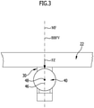
- the element 40 sits, for example, on a carrier 42, which is connected to the second end region 34 of the holding arm 30 and extends, starting from a roadway 44 on the side facing away from the carrier 42, in the direction of a central axis 46 that runs approximately vertically when the roadway 44 is horizontal, which in the case of of the coupling ball runs through a ball center 48 .
- the cross member 22 is preferably arranged under a rear bumper unit 50 of the motor vehicle body 12, the bumper unit 50 covering, for example, the cross member 22 and the first end 32 of the holding arm 30.
- the holding arm 30 is shown schematically as a rectangular bar, with the holding arm 30 being able to have any desired shape, as can also be seen from the following exemplary embodiments.
- the representation of the holding arm 30 as a rectangular bar in connection with the first exemplary embodiment makes it possible to represent in a simplified manner the conditions that are essential for the invention when the element 40 is loaded with forces acting in different directions and the resulting reversible deformations.
- the force FZ acting in the vertical direction and in the direction of gravity thus causes a vertical bending load at least in the holding arm section 60, which means that the holding arm section 60 is stretched on an upper transverse side 62 in relation to the force of gravity and on a lower transverse side in the direction of gravity 64 undergoes compression, so that material bending stresses MBSz caused by the bending moment occur near the upper transverse side 62, while material bending stresses -MBSz occur near the lower transverse side 64 of the holding arm section, which are caused by the material compression on the lower transverse side 64.
- the vertical neutral fiber is NFV, as in 4 shown, in the centroid FS of any cross-sectional area QF of the holding arm section 60 and thus, for example, in a first approximation in the middle between the upper transverse side 62 and the lower transverse side 64.
- the holding arm section 60 has a vertical neutral layer NSV that extends over the entire width of the holding arm section 60 and is determined by a vertical neutral reference surface NRFV, which on the one hand runs through the vertical neutral fiber NFV and in a transverse direction to the vertical neutral fiber NFV, in particular perpendicular to the vertical neutral fiber NFV and, according to the invention, perpendicular to a bending movement surface BBFV that forms under the vertical bending load BV.
- NRFV vertical neutral reference surface
- the vertical bending movement area BBFV is defined as the area that passes through the neutral line NFV and parallel to which the support arm section 60 moves under the vertical bending load BV with the smallest possible, in particular without lateral movements.
- the vertical neutral reference surface NRFV runs in an approximation perpendicular to a central surface MF of the holding arm section 60 parallel to the vertical, which runs through a centroid FS of each cross-sectional area QF of the holding arm section 60 and thus through the vertical neutral fiber NFV.
- element 40 is subjected to a load by a horizontal transverse force FY which is perpendicular to the vertical force FZ and, for example, also runs perpendicular to the central surface MF
- the holding arm 60 bends in such a way that at a point between the upper transverse side 62 and the lower Material elongation and thus a positive material bending stress MBS Y occurs on the longitudinal side 66 extending across the transverse side 64, while material compression and thus a negative material bending stress -MBS Y occurs on the opposite longitudinal side 68, which also extends between the upper transverse side 62 and the lower transverse side 66.
- transverse bending load BQ also leads to the formation of a transverse neutral fiber NFQ, which in the illustrated embodiment according to 4 due to the symmetrical design of the holding arm section 60 coincides with the neutral fiber NFV.
- the neutral fiber NFQ can run and be positioned differently than the neutral fiber NFV.
- a transverse neutral layer NSQ also forms in the holding arm section 60, in which there is no expansion or compression of the material and therefore no material stresses MS occur either.
- the neutral layer NSQ extends in a transverse neutral reference surface NRFQ running perpendicularly to the horizontal transverse force FY, which in the simplified exemplary embodiment coincides with the central surface MF, for example.
- the transverse neutral reference surface NRFQ runs on the one hand through the transverse neutral fiber NFQ and also perpendicular to a transverse bending movement surface BBF, which runs through the neutral fiber NFQ and parallel to which the holding arm section 60 moves at the transverse bending load BQ with the smallest possible, in particular without transverse movements.
- transverse neutral reference surface NRFQ also runs perpendicular to the vertical neutral reference surface NRFV, which is due to the fact that the vertical force FZ and the horizontal transverse force FY run perpendicular to one another.
- element 40 can also be subjected to a tensile load by a horizontal longitudinal force FX, which corresponds to an acceleration force that runs perpendicularly to the vertical force FZ and perpendicularly to the horizontal transverse force FY and is directed away, for example, from the rear area 14 of the motor vehicle body 12, so that due to of the horizontal longitudinal force FX in the holding arm section 60 form tensile stresses MZSx, which, however, run parallel to one another and in the same direction over the respective cross-sectional areas QF and are equal in a first approximation, the horizontal longitudinal force FX preferably being approximately parallel when the motor vehicle 10 is traveling on a horizontal roadway is aligned to the vehicle longitudinal direction 24.
- a horizontal longitudinal force FX which corresponds to an acceleration force that runs perpendicularly to the vertical force FZ and perpendicularly to the horizontal transverse force FY and is directed away, for example, from the rear area 14 of the motor vehicle body 12, so that due to of the horizontal longitudinal force FX in the holding arm section 60 form
- the holding arm 30 is also aligned in such a way that it runs horizontally and parallel to the longitudinal direction 24 of the vehicle, so that the horizontal longitudinal force FX exclusively leads to a uniform material expansion over the respective cross-sectional area QF and thus to material stresses MZSx of the same magnitude.
- the carrier unit 20, the holding arm 30 and the element 40 form a device 70 according to the invention for towing a trailer and/or holding a load carrier unit.
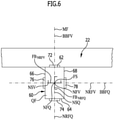
- the holding arm 30 is in the holding arm section 60 with strain sensors 72 and 74 arranged on the transverse sides 62 and 64 and Strain sensors 76 and 78 arranged on the longitudinal sides 66 and 68 are provided.
- the strain sensors 72 and 74 are arranged on both sides of a surface area FB NRFV , which represents a partial area of the vertical neutral reference surface NRFV and has a maximum of 1.5 times the extent of the strain sensors 72 in its various directions of expansion ARX, ARY located in the vertical neutral reference surface NRFV , 74 in these extension directions ( 6 , 7 ).
- a perpendicular projection of the strain sensors 72, 74 onto the vertical neutral reference surface NRFV lies within the surface area FB NRFV , as in FIG figure 5 and 7 represented by the strain sensor 72.
- the strain sensors 72 and 74 thus detect the material stresses MBS generated by the vertical bending load in the same volume region of the holding arm section 60 and detect opposing material bending stresses under the vertical bending load, which in the first exemplary embodiment are arranged essentially at the same distance from the vertical neutral reference surface NRFV , 74 result in signals of the opposite sign but of the same magnitude, preferably approximately the same magnitude.
- the strain sensors 72, 74 can thus be used, for example, to determine a static load with the force FZ, with the force FZ representing a vertical load of a trailer or a load carrier unit in the case of the device according to the invention, which acts on the element 40 of the holding arm 30.
- the strain sensors 76 and 78 are located on opposite sides of the transverse neutral reference plane NRFQ and are positioned relative to a surface area FB NRFQ such that the strain sensors 76 and 78 when projected perpendicularly onto the Transverse neutral reference surface NRFQ lie within the surface area FB NRFQ , with the surface area FB NRFQ in its expansion directions lying in the surface area FB NRFQ each having an expansion which corresponds at most to 1.5 times the expansion of the strain sensors 76, 78 parallel to these directions.
- a normal projection of the strain sensors 76 and 78 also lies within the area FB NRFQ .
- a transverse bending load BQ will also cause the strain sensors 76, 78 to produce signals of the opposite sign, but of the same magnitude, preferably approximately the same magnitude.
- the horizontal transverse force FY determined by the sensors 76, 78 represents, in particular in the device according to the invention, a transverse acceleration on the element 40, which occurs, for example, during the driving operation of the motor vehicle when the motor vehicle or the motor vehicle with the trailer or with the load carrier unit swerve.
- Such a horizontal longitudinal force FX represents, in particular in the device according to the invention, a tractive force when the motor vehicle is being driven, which acts on element 40, with the mass of the trailer acting on element 40 or the mass of the trailer acting on element 40 being derived from this tractive force when the acceleration is known Load carrier unit can be determined.
- an evaluation unit AU which detects the signals from strain sensors 72, 74 and possibly also 76, 78 and uses them to determine the vertical load FZ on element 40 when the motor vehicle is stationary, for example by using a table that Assigns signals from the strain sensors to a support load, and then determines the tensile force FX and, if necessary, the lateral force FY while driving, taking into account the measured support load FZ, for example also by using a table that contains the values for the support load and the signals from the strain sensors when driving with a value linked for the tensile force.
- the evaluation unit AU is also able to determine the mass of a trailer acting on the element 40 or of a load carrier unit held on the element 40, with the arrangement of the acceleration sensor BSH in the evaluation unit, the value for the acceleration is simply available synchronously with the tensile force FX for determining the mass.
- the holding arm section 60 is provided with an opening 80, which extends, for example, from the long side 66 to the long side 68 and approximately parallel to the vertical neutral reference surface NRFV and which lies on both sides of the neutral reference plane NRFV, the stability of the holding arm section 60 on both sides of the opening 80 is ensured by an upper chord 82 and a lower chord 84 of the holding arm section 60 .
- the opening 80 has an insignificant effect on the stability of the holding arm 30 and thus also of the holding arm section 60 with regard to deflection under a bending load caused by the vertical force FZ, since with such a load, as explained above, close to the neutral reference plane NRFV, which on the one hand through the neutral fiber NFV and on the other hand, only slight material stresses MBSz occur transversely to this, in particular perpendicular to the bending stress surface BBFV, which make no significant contribution to the stability of the holding arm 30 against a vertical bending stress caused by the application of the vertical force FZ.
- a sensor unit designated as a whole by 90 , is arranged in this opening 80 , which has a sensor carrier 92 extending in a longitudinal direction 93 , which is arranged such that the neutral reference plane NRFV passes through the sensor carrier 92 in a central volume region 94 .
- the sensor carrier 92 has sensor carrier surfaces 102, 104 on opposite sides of the vertical neutral reference surface NRFV, which preferably have essentially the same distance from the vertical neutral reference surface NRFV and run essentially parallel to the vertical neutral reference surface NRFV. Strain sensors 106 and 108 are arranged on these sensor carrier surfaces 102 and 104 and detect material strains.
- Sensor carrier 92 is fixedly connected to holding arm section 60 by a first end region 112 and a second end region 114, between which sensor carrier surfaces 102 and 104 lie, but extends at least in the region of its sensor carrier surfaces 102 and 104 independently of the holding arm section 60, so that the strain sensors 106 and 108 resting on the sensor carrier surfaces 102 and 104 only detect the strains occurring in the sensor carrier 92 on both sides of the vertical neutral reference surface NRFV.
- First end area 112 and second end area 114 of sensor carrier 92 are connected to holding arm section 60 in such a way that sensor carrier 92 experiences the same material stresses MBSz as would be experienced by a corresponding volume area of holding arm section 60 .
- connection between the first end region 112 and the second end region 114 of the sensor carrier 92 takes place through recesses 116 and 118 provided in the holding arm section 60 on both sides of the opening 80, which form-fittingly encompass the end regions 112 and 114 and thus accommodate the reversible occurring in the holding arm section 60 Deformations are transferred at least qualitatively to the sensor carrier 92.
- the strain sensors 106 and 108 are preferably arranged on opposite sides of the vertical neutral reference surface NRFV, namely on both sides of a surface area FBNRFV which has a maximum of 1.5 times the extent of the strain sensors 106 and 108 in the respective direction of extent, so that the strain sensors 106, 108 are arranged essentially mirrored to the vertical neutral reference surface NRFV in order to detect the strains or compressions that occur.
- the distances A102 and A104 of the sensor carrier surfaces 102 and 104 from the vertical neutral reference surface NRFV are preferably chosen such that one of the distances A102, A104 is at most 1.5 times the other of the distances A104 or A102.
- the sensor carrier 92 is provided with sensor carrier surfaces 122, 124 running transversely to the sensor carrier surfaces 102 and 104, which are arranged on opposite sides of the transverse neutral reference surface NRFQ and on which strain sensors 126 and 128 are arranged.
- the sensor carrier 92 is coupled to the holding arm section 16 by fixing its end regions 112 and 114 in the recesses 116 and 118 in such a way that the sensor carrier 92 shows qualitatively the same bends as the holding arm section 60 in the region, even when the holding arm 30 is subjected to loads by the horizontal transverse force FY the upper chord 82 and the lower chord 84.
- strain sensors 126, 128 are used to detect the strains corresponding to the material stresses MBS Y and -MBS Y .
- These sensor support surfaces 122, 124 are also arranged at distances A122 and A124 from the transverse neutral reference surface NRFQ, with one of the distances A122, A124 being less than 1.5 times the distance A124 or A122.
- the strain sensors 126 and 128 are located on opposite sides of a surface area FBNRF Q , the surface area FB NRFQ having an extent in the individual directions of extent which is a maximum of 1.5 times the corresponding extent of the respective strain sensor 126, 128, so that the strain sensors 126, 128 are arranged essentially mirrored on the neutral reference surface NRFQ on both sides thereof and thus detect the strain of the material of the sensor carrier 92 essentially at the same location on opposite sides of the neutral reference surface NRFQ.
- strain sensors 126 and 128 respond in the same way to strains caused by the horizontal longitudinal force FX such that they detect the same strain on either side of the sensor carrier 92, as is the case with the strain sensors 106 and 108.
- the positioning of the receptacles 116 and 118 relative to the first end region 32 of the retaining arm 30 and the second end region 34 of the retaining arm 30 takes place in particular in such a way that their distances AE116 and AE118 relative to one another are dimensioned such that one of the distances AE116, AE118 is less than that 1.5 times the other of the distances AE118 or AE116, in particular the two distances AE116 and AE118 are essentially the same size.
- the sensor carrier 92 with the strain sensors 106 and 108 or 126 and 128 allows the influences of the vertical bending load BV, the transverse bending load BQ and the horizontal tensile load to be detected by the force in the longitudinal direction FX either individually or when they are superimposed.
- strain sensors 106, 108 or 126, 128 detect material bending stresses with different signs during the bending loads on opposite sides of the corresponding vertical neutral reference surface NRFV and NRFQ, i.e. strains on the one hand and compressions on the other, while strain sensors 106 and 108 and 126 and 128, respectively, upon exposure of the horizontal longitudinal force FX essentially detect the same material tensile stresses in the respective cross-sectional areas QF of the holding arm section 60 on both sides of the respective vertical neutral reference area NRFV or transverse neutral reference areas NRFQ.
- the vertical bending load and the horizontal bending load can generate measurement signals from strain sensors 106 and 108 or 126 and 128, either individually or in superimposition with the horizontal tensile load, which can then be used to draw conclusions about the individual components of the vertical force FZ, the horizontal shear force FY and the horizontal Allow longitudinal force FX.
- the carrier unit 20 is also provided on the rear area 14 of the motor vehicle body 12 of the motor vehicle 10, which also includes the cross member 22, for example, which is connected to the rear area 14 of the motor vehicle body 12 by means of side supports 26.
- the cross member 22 is arranged covered by the bumper unit 50 .
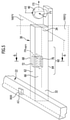
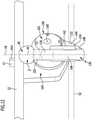
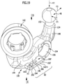
- the support arm 130 also carries the element 40 designed as a coupling ball, with the support arm 30, as in particular in FIGS 11 and 12 shown, extending from a pivot bearing unit 140 to which the holding arm 130 is connected at its first end region 132, a pivot bearing body 142 of the pivot bearing unit 140 being formed on the first end region 132, for example.
- the holding arm 130 then extends in this exemplary embodiment with a first curved piece 144 to an intermediate piece 146, which is followed by a second curved piece 148, which in turn carries the element 40 designed as a coupling ball, with between the coupling ball trained element 40 and the second arcuate piece 148 is still a ball socket 152 is provided.
- the second curved piece 148 then forms the end region 134 of the holding arm 130 which then carries, for example, the ball attachment 152 to which the element 40 designed as a coupling ball is connected.
- a ring body 154 is formed in the second elbow piece 148 for easy mounting of a contact unit on the holding arm 130, which ring body 154 encloses a passage 156 in which a contact unit can be mounted.
- the ring body 154 is preferably arranged in the second curved piece 148 in such a way that, following the ring body 154 , a transition piece 158 is used to make a transition into the intermediate piece 146 of the holding arm 130 .
- Pivot bearing body 142 of pivot bearing unit 140 is mounted on a pivot bearing receptacle 162 so that it can pivot about a pivot axis 160 that runs, in particular, obliquely to a vertical longitudinal center plane 18 of the vehicle of the holding arm 130 relative to pivoting movements about the pivot axis 160.
- the pivot bearing body receptacle 162 is then in turn firmly connected to the cross member 62 via a pivot bearing base 164 .
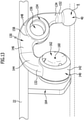
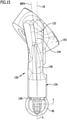
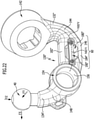
- the holding arm 130 in this third exemplary embodiment is from a working position A, shown in FIG 11 and 12 , in which the element designed as a coupling ball 40 is in such a way that it is behind the bumper unit 50 on a side facing away from a roadway 42, into a rest position R, shown in FIG 13 , is pivotable, in which the element 40 of the roadway 42 is arranged facing.
- the element 40 can be moved under a lower edge 52 of the bumper unit 50 .
- the holding arm 130 extends in the working position A essentially in the vertical longitudinal center plane 18 of the vehicle, whereby this intersects the element 40 in the middle if it is designed as a coupling ball, so that a vertical ball center axis 44 lies in the longitudinal center plane 18.
- the holding arm 130 is approximately U-shaped by the first arcuate piece 144, the intermediate piece 146 and the second arcuate piece 148, and is aligned in this way in the working position A, in which loads of the element 40 occur and are to be detected that, for example, the forces FX and FZ, which act on the element 40, in particular the ball center 46, are transmitted to the pivot bearing body 142 of the pivot bearing unit 140 via the approximately U-shaped design of the retaining arm 130, with a center point of the force absorption being through the pivot bearing unit 140 the pivot axis 160 represents.
- the intermediate piece 146 preferably comprises the holding arm section 60, in which the reversible deformations, which are caused, for example, by the forces FX and FZ ( 14 ) act on the holding arm 130.
- the vertical force FZ acting in the direction of gravity on the element 40 also leads to a pure bending of the same in the area of the intermediate piece 146, so that a vertical neutral fiber NFV and a vertical neutral reference surface NRFV are also formed in the holding arm section 60 , wherein the neutral reference surface NRFV runs through the vertical neutral fiber NFV and transverse to the vertical bending movement surface BBFV, which extends parallel to the vertical force FZ in the direction of gravity and defines the surface in which the holding arm 130 moves when acted upon by the vertical force FZ in the direction of gravity FZ moves and avoids as little as possible across to it.
- the bending movement surface BBFV runs with a holding arm 130, as shown in FIGS 12 and 13 shown, is not exactly parallel to or coincident with the longitudinal center plane 18 of the vehicle, but at least partially inclined relative to it, since the holding arm 130, as in 12 shown, also does not run symmetrically to the vertical longitudinal center plane 18 of the vehicle.
- FIG 15 An exemplary course of the vertical bending movement area BBFV when loaded by the vertical force FZ in the direction of gravity FZ is shown in FIG 15 shown.
- the loading of the holding arm 130 with the vertical force FZ in the direction of gravity thus leads to a bending load in the holding arm section 60 in the same way as in the first and second exemplary embodiment.
- the arrangement of the holding arm section 60 for detecting the reversible deformations of the same takes place in the case of the holding arm 130 in the intermediate piece 146, since this extends between the curved pieces 144 and 148 with a significant component parallel to the horizontal longitudinal direction X, in which the horizontal longitudinal force FX acts, see above that in the holding arm section 60 running parallel to the horizontal longitudinal direction X expansions occur.
- a horizontal longitudinal force FX not only leads to pure material tensile stresses MZSx in the holding arm section 60, but also to a material bending stress MBSx, since the horizontal longitudinal force FX with a lever arm H1 acts on the holding arm section 60 and the holding section 60 also acts again via the lever arm H2 on the pivot bearing body 142 which ultimately fixes the holding arm 130 .
- the horizontal longitudinal force FX has the result that both material tensile stresses MZSx, which have the same sign over the entire cross section, and material bending stresses MBSx, which have a different sign on one side of the vertical neutral reference surface NRFV than on the opposite side.
- strain sensors 172 and 174 are provided on both sides of the limited surface area FB NRFV of the vertical neutral reference surface NRFV, which lie directly on the outer surfaces of the intermediate piece 146, for example, and thus detect the strains that occur on both sides of the vertical neutral reference surface NRFV.
- the strain sensors 172 and 174 are preferably arranged at distances A172 and A174 from the neutral reference surface NRFZ, which are approximately the same size, preferably so large that one of the distances A172, A174 is less than 1.5 times the distances A174 or A172 is.
- one of the strain sensors 172, 174 measures a lower strain than the other of the strain sensors 172, 174, since the total material tensile stresses MZSx and the material bending stresses MBSx affect the strains to be measured.
- the evaluation unit AU determines the force FZ and thus the support load from the signals of the expansion sensors 172, 174 in the static state, i.e. not during driving, and when driving when the support load is known FZ, the tractive force FX and, taking into account the acceleration determined with the acceleration sensor BSH in the horizontal longitudinal direction X, the mass of the trailer or the load carrier unit.
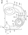
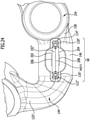
- FIGS 17 and 18 in a fourth embodiment of the solution according to the invention, shown in FIGS 17 and 18 similar to the second exemplary embodiment, in the intermediate piece 146 forming the holding arm section 60 there is an opening 180 which extends parallel to the vertical neutral reference surface NRFV and penetrates the holding arm section 60, which is delimited by an upper chord 182 and a lower chord 184 and in which a sensor unit 190 is arranged which has a sensor carrier 192 through which the vertical neutral reference surface NRFV passes in a central volume region 194 in the same way as in the second exemplary embodiment.
- Sensor carrier 192 carries strain sensors 206 and 208 arranged on sensor carrier surfaces 202 and 204, which, in the same way as in the second exemplary embodiment, are capable of absorbing the material stresses MBSz, MBSx and MZSx occurring in sensor carrier 192 via the sensor carrier 192 in the area of the sensor carrier surfaces 102 and 104 occurring stretching or compression.
- sensor carrier 192 is also coupled directly to holding arm section 60 in that sensor carrier 192 is a part connected in one piece to the rest of holding arm section 60, so that all reversible deformations of holding arm area 60 are qualitatively transferred to sensor carrier 192 and thus to the sensor carrier 192 qualitatively the same expansions and compressions can be detected by the expansion sensors 202 and 204.
- the strain sensors 206, 208 can thus be used to determine a static load with the force FZ, for example, with the force FZ representing a vertical load of a trailer or a load carrier unit in the case of the device according to the invention, which acts on the element 40 of the holding arm 130'.
- Such a horizontal longitudinal force FX represents, in particular in the device according to the invention, a tractive force when the motor vehicle is being driven, which acts on element 40, with the mass of the trailer acting on element 40 or the mass of the trailer acting on element 40 being derived from this tractive force when the acceleration is known Load carrier unit can be determined.
- an evaluation unit AU is also provided on sensor carrier 192, which detects the signals from strain sensors 206, 208 and uses them to determine support load FZ on element 40 when the motor vehicle is stationary, for example by using a table which the signals of the strain sensors 206, 208 to a support load, and then during driving operation, taking into account the measured support load FZ, determining the tractive force FX, for example also by using a table that contains the values for the support load and the signals from the strain sensors during driving operation with a value for the tractive force connected.
- an acceleration sensor BSH that detects the acceleration in the horizontal longitudinal direction X is also provided in the evaluation unit AU, so that the evaluation unit AU is also able to determine the mass of a trailer acting on the element 40 or of a load carrier unit held on the element 40.
- the holding arm 130' is designed in principle in the same way as in the third exemplary embodiment, although the sensor unit 190' with the sensor carrier 192' is arranged on the intermediate piece 146 comprising the holding arm section 60 to the side of the intermediate piece 146, but also in such a way that the vertical Neutral reference surface NRFV passes through sensor carrier 192' in a central volume region 194' and this sensor carrier 192' therefore also has sensor carrier surfaces 202 and 204, which are arranged on opposite sides of neutral reference surface NRFZ in the same way as in the second and fourth exemplary embodiments, so that on these sensor carrier surfaces Strain sensors 206 and 208 arranged 202 and 204 also detect strains and compressions of the sensor carrier 192' in the same size arrangement.
- Sensor carrier 192' is preferably firmly connected to intermediate piece 146 at its end regions 212 and 214, so that sensor carrier 192 experiences qualitatively the same reversible deformations as intermediate piece 144, which includes holding arm section 60, in the same way as in the second and fourth exemplary embodiments.
- This solution has the advantage that it is not necessary to change the holding arm 130' itself, for example by making the opening 80, but rather that the holding arm 130' can be designed unchanged in its holding arm section 60, and only on one side, for example, or also on the opposite side Sides of the holding arm section 60, the sensor carrier 192' can be mounted in such a way that the vertical neutral reference surface NRFV passes through a central volume area 194' of the same.
- the strain sensors 206, 208 can thus be used to determine a static load with the force FZ, for example, with the force FZ representing a support load of a trailer or a load carrier unit in the case of the device according to the invention, which acts on the element 40 of the holding arm 130.
- Such a horizontal longitudinal force FX represents, in particular in the device according to the invention, a tractive force when the motor vehicle is being driven, which acts on element 40, with the mass of the trailer acting on element 40 or the mass of the trailer acting on element 40 being derived from this tractive force when the acceleration is known Load carrier unit can be determined.
- an evaluation unit AU is provided on sensor carrier 192', which detects the signals from strain sensors 206, 208 and uses them to determine support load FZ on element 40 when the motor vehicle is stationary, for example by using a table which assigns the signals from the strain sensors to a support load, and then determines the tractive force FX while driving, taking into account the measured support load FZ, for example also by using a table which links the values for the support load and the signals from the strain sensors during driving with a value for the tractive force .
- an acceleration sensor BSH that detects the acceleration in the horizontal longitudinal direction X is also provided in the evaluation unit AU, so that the evaluation unit AU is also able to determine the mass of a trailer acting on the element 40 or of a load carrier unit held on the element 40.
- FIGS Figures 22 to 25 Those elements that are identical to those of the preceding exemplary embodiments are provided with the same reference symbols, so that with regard to the explanations of these elements, reference can be made in full to the explanations relating to the preceding exemplary embodiments.
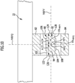
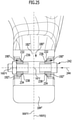
- the holding arm 130" in the region of the intermediate piece 146, which forms the holding arm section 60 is again provided with an opening 180" that extends parallel to the vertical neutral reference surface NRFV and which cuts the entire holding arm section 60 in a direction parallel to the vertical neutral reference surface NRFV interspersed in such a way that the vertical neutral reference surface NRFV runs through the opening 180" and on both sides of the opening 180" the upper chord 182" and the lower chord 184" bring about the necessary stability of the intermediate piece 146.
- Sensor units 190" are inserted into the opening 180" from both sides, each of which includes a sensor carrier 192", the sensor carrier 192" also being arranged such that a central volume area 194" is penetrated by the vertical neutral reference surface NRFV.
- each of the sensor carriers 192" is provided with sensor carrier surfaces 202 and 204 which are arranged essentially equidistantly on opposite sides of the vertical neutral reference surface NRFV and are thus able to detect the reversible deformations of the sensor carrier 192".
- a detachable connection of the sensor carrier 192" to the holding arm section 60 is made, for example, by screwing end regions 112" and 114" of the respective sensor carrier 192" to the holding arm section 60, with, as in 25 shown, the sensor carriers 192" have form-fitting surfaces 232, 234, which can be placed on corresponding receiving surfaces 236, 238 in order to produce a form-fitting connection to the holding arm section 60 at the respective end regions 112" and 114" of the sensor carriers 192".
- the form-fitting surfaces 232 and 234 and the receiving surfaces 236 and 238 are arranged in such a way that the end regions 112" and 114" of the sensor carrier 292" can be fixed to the holding arm section 60 by a screw connection 242.
- the screw connection 242 causes the end regions 212" and 114" of the sensor carrier 192" to be pressed into the recesses 116" and 118" in an insertion direction 244, which runs parallel to the vertical neutral reference surface NRFV, for example, with the receiving surfaces 236 and 238 respectively obliquely to the direction of insertion 244 and relative to each other conical or V-shaped.
- the form-fitting surfaces 232 and 234 have a similar orientation that runs obliquely to the direction of insertion 244 and in a V-shape with respect to one another, so that the screw connection 242 creates a non-rotatable, form-fitting connection between the recesses 116", 118" and the respective end regions 112" or 114" in order to to transfer the reversible deformations of the holding arm section 60 at least qualitatively to the respective sensor carrier 192".
- the sensor units 190′′ are units that can be produced separately, which can be exchanged, for example, in the event of damage, and which can also be used with holding arms 130′′ of different shapes.
- the sensor carrier 192" is made of a material which has the same coefficient of thermal expansion as the material of the holding arm section 60 and stresses in the sensor carrier 192" are avoided with temperature changes.
- the sensor carrier 192'' is made of the same material as the support arm portion 60.
- the sensor units 190" are arranged on opposite sides of the transverse neutral reference surface NRFQ, so that there is also the possibility of different strains detected by one sensor unit 190" in relation to the other sensor unit 190" due to the horizontal transverse force FY generated reversible deformations in the holding arm section 60 to be detected.
- this can thus be determined, for example, in the event of a static load with the force FZ, in the case of the device according to the invention the force FZ representing a support load of a trailer or a load carrier unit which is applied to the element 40 of the support arm 30 acts.
- the respective strain sensors 206, 208 of the two spaced-apart sensor units 190" are thus also arranged on opposite sides of the transverse neutral reference plane NRFQ and relative to a surface area FB NRFQ so arranged so that the respective strain sensors 206, 208 of the two sensor units 190" lie within the surface area FB NRFQ in a vertical projection onto the transverse neutral reference surface NRFQ, with the surface area FB NRFQ each having an extent in its expansion directions lying in the surface area FB NRFQ , which corresponds to a maximum of 1.5 times the expansion of the strain sensors 206, 208 parallel to these directions.
- a perpendicular projection of the strain sensors 206 and 208 of each of the sensor units 190'' also lies within the area FB NRFQ .
- a transverse bending load BQ also causes signals with the opposite sign in the respective strain sensors 206, 208 of the two sensor units 190", but in the same order of magnitude , preferably about the same size.
- the horizontal transverse force FY determined by the sensors 206, 208 of the two sensor units 190" represents, particularly in the device according to the invention, a transverse acceleration on the element 40, which occurs, for example, during the driving operation of the motor vehicle when the motor vehicle or the motor vehicle with the trailer or with the load carrier unit swerve appear.
- Such a horizontal longitudinal force FX represents, in particular in the device according to the invention, a tractive force when the motor vehicle is being driven, which acts on element 40, with the mass of the trailer acting on element 40 or the mass of the trailer acting on element 40 being derived from this tractive force when the acceleration is known Load carrier unit can be determined.
- an evaluation unit AU is provided on one of the sensor carriers 190", in particular, which detects the signals from the strain sensors 206, 208 of the two sensor units 190" and from this determines the support load FZ on the element 40 when the motor vehicle is stationary, for example by using a Table that assigns the signals from the strain sensors to a vertical load, and then during driving operation, taking into account the measured vertical load FZ, determines the tensile force FX and, if applicable, the lateral force FY, for example also by using a table that contains the values for the vertical load and the signals from the strain sensors 206 , 208 linked to a value for the tractive effort while driving.
- an acceleration sensor BSH that detects the acceleration in the horizontal longitudinal direction X is also provided in the evaluation unit AU, so that the evaluation unit AU is also able to determine the mass of a trailer acting on the element 40 or of a load carrier unit held on the element 40.
Description
Die Erfindung betrifft eine heckseitig an einer Kraftfahrzeugkarosserie montierbare Vorrichtung zum Ziehen eines Anhängers und/oder Halten einer Lastenträgereinheit, umfassend einen mit einem ersten Endbereich mit der Kraftfahrzeugkarosserie verbundenen Haltearm, der an einem zweiten Endbereich mit einem Element zum Anhängen des Anhängers und/oder zum Fixieren der Lastenträgereinheit versehen ist, und ferner umfassend Sensoren zum Erfassen von durch Belastungen des Haltearms bedingten reversiblen Deformationen des Haltearms.The invention relates to a device for towing a trailer and/or holding a load carrier unit that can be mounted on the rear of a motor vehicle body, comprising a holding arm connected to the motor vehicle body at a first end area and having an element for attaching the trailer and/or for fixing at a second end area of the load carrier unit, and further comprising sensors for detecting reversible deformations of the holding arm caused by loads on the holding arm.
Eine derartige Vorrichtung ist beispielsweise aus der
Bei dieser Vorrichtung ist es jedoch nicht in einfacher Weise möglich, die mit mehreren Sensoren an verschiedenen Stellen des Haltearms erfassten Dehnungen einzelnen Krafteinwirkungen zuzuordnen.With this device, however, it is not possible in a simple manner to assign the strains detected with a number of sensors at different points on the holding arm to individual force effects.
Der Erfindung liegt daher die Aufgabe zugrunde, eine Vorrichtung zur Verfügung zu stellen bei welcher eine Zuordnung von erfassten Dehnungen zu einzelnen Krafteinwirkungen in möglichst einfacher Weise möglich ist.The invention is therefore based on the object of making available a device in which it is possible to assign measured strains to individual force effects in the simplest possible manner.
Diese Aufgabe wird bei einer Vorrichtung der eingangs beschriebenen Art erfindungsgemäß dadurch gelöst, dass einem Haltearmabschnitt des Haltearms durch dessen reversible Deformationen beeinflusste Dehnungssensoren zugeordnet sind und dass zur Erfassung von mindestens einer ausgewählten Biegebelastung mindestens ein Dehnungssensor auf einer Seite und mindestens ein Dehnungssensor auf einer gegenüberliegenden Seite eines Flächenbereichs einer der ausgewählten Belastung zugeordneten Neutralreferenzfläche angeordnet sind und dass die Dehnungssensoren jeweils in einem Abstand von diesem Flächenbereich angeordnet sind.In a device of the type described above, this object is achieved according to the invention in that a holding arm section of the holding arm is assigned strain sensors that are influenced by its reversible deformations and that, for detecting at least one selected bending load, there is at least one strain sensor on one side and at least one strain sensor is arranged on an opposite side of a surface area of a neutral reference surface associated with the selected load and that the strain sensors are each arranged at a distance from this surface area.
Der Abstand des jeweiligen Dehnungssensors von dem Flächenbereich beträgt beispielsweise mindestens 2 mm, noch besser mindestens 4 mm, vorzugsweise mindestens 6 mm.The distance of the respective strain sensor from the surface area is, for example, at least 2 mm, even better at least 4 mm, preferably at least 6 mm.
Der Vorteil der erfindungsgemäßen Lösung ist somit darin zu sehen, dass durch die Anordnung von mindestens einem Dehnungssensor auf einander gegenüberliegenden Seiten des Flächenbereichs der Neutralreferenzfläche die Möglichkeit besteht, die ausgewählte Dehnung dadurch zu erfassen, dass die auf den unterschiedlichen Seiten der Neutralreferenzfläche angeordneten Dehnungssensoren Dehnungen mit unterschiedlichem Vorzeichen, das heißt einmal eine Dehnung und einmal eine Stauchung, erfassen und somit der Beitrag der Biegebelastung zu dem den von den Dehnungssensoren gemessenen Dehnungen einfacher ermittelt werden kann.The advantage of the solution according to the invention can therefore be seen in the fact that the arrangement of at least one strain sensor on opposite sides of the surface area of the neutral reference surface makes it possible to detect the selected strain in that the strain sensors arranged on the different sides of the neutral reference surface detect strains with different signs, that is, once a strain and once a compression, detect and thus the contribution of the bending load to the measured by the strain sensors strains can be determined more easily.
Ein weiterer Vorteil der erfindungsgemäßen Lösung ist darin zu sehen, dass die Dehnungssensoren auf unterschiedlichen einander gegenüberliegenden Seiten eines Flächenbereichs der Neutralreferenzfläche, das heißt einer Teilfläche der Neutralreferenzfläche, liegen, so dass dadurch die Dehnungssensoren die von demselben Volumenbereich des Haltearms ausgeführten reversible Deformationen einmal als Dehnung und einmal als Stauchung erfassen.A further advantage of the solution according to the invention can be seen in the fact that the strain sensors are located on different opposite sides of a surface area of the neutral reference surface, i.e. a partial surface of the neutral reference surface, so that the strain sensors record the reversible deformations carried out by the same volume area of the holding arm as strain and record it once as a compression.
Im Sinne der erfindungsgemäßen Lösung ist unter einer Neutralreferenzfläche diejenige Fläche zu verstehen, die einerseits durch die sich bei der ausgewählten Biegebelastung ausbildende neutrale Faser im Haltearm verläuft und die andererseits sich quer zu einer Biegebewegungsfläche erstreckt.In terms of the solution according to the invention, a neutral reference surface is to be understood as that surface which runs through the neutral fiber in the holding arm that forms under the selected bending load and which also extends transversely to a bending movement surface.
Unter einer Biegebewegungsfläche im Sinne der erfindungsgemäßen Lösung ist dabei diejenige Fläche zu verstehen, parallel zu welcher sich der Haltearm bei einer durch eine Krafteinwirkung in einer einzigen definierten Richtung ausgelösten Biegebelastung mit der geringsten Querbewegung zu dieser Fläche bewegt und die durch die sich bei dieser Biegebelastung ergebende neutrale Faser des Haltearms hindurchverläuft.A bending movement area in the context of the solution according to the invention is to be understood as the area parallel to which the holding arm moves with the smallest transverse movement to this area when a force is applied in a single defined direction and the resultant bending load through the neutral axis of the holding arm.
Gemäß einer Näherung verläuft die Biegebewegungsfläche parallel zur Richtung der Krafteinwirkung und durch die jeweilige neutrale Faser hindurch.According to an approximation, the bending motion surface runs parallel to the direction of the force application and through the respective neutral axis.
Ferner ist bei einer groben Näherung die Vertikalbiegebewegungsfläche bei einem gekrümmten Haltearm eine mittig durch alle Abschnitte des Haltearms und näherungsweise parallel zur Richtung der vertikalen Krafteinwirkung verlaufende Fläche.Also, to a rough approximation, the surface of vertical flexing movement for a curved support arm is a surface running centrally through all portions of the support arm and approximately parallel to the direction of vertical force application.
Unter einem näherungsweise parallelen Verlauf ist insbesondere ein von einem exakt parallelen Verlauf um maximal ± 30°, noch besser maximal ± 20°, abweichender Verlauf zu verstehen.An approximately parallel course is to be understood in particular as a course deviating from an exactly parallel course by a maximum of ±30°, even better by a maximum of ±20°.
Ist es im Rahmen der erfindungsgemäßen Vorrichtung erforderlich, mehrere Biegebelastungen zu erfassen, so ist jeder Biegebelastung eine Neutralreferenzfläche zugeordnet.If, within the scope of the device according to the invention, it is necessary to record a number of bending loads, then each bending load is assigned a neutral reference surface.
Insbesondere ist im Rahmen der erfindungsgemäßen Lösung vorgesehen, den Haltearm einer Vertikal-Biegebelastung und einer Quer-Biegebelastung auszusetzen, wobei bei einer Vertikal-Biegebelastung auszusetzen, wobei bei einer Vertikal-Biegebelastung sich eine Vertikal-Neutralreferenzfläche ausbildet und bei einer Quer-Biegebelastung sich eine Quer-Neutralreferenzfläche ausbildet.In particular, the solution according to the invention provides for the holding arm to be subjected to a vertical bending load and a transverse bending load, with a vertical bending load being suspended, with a vertical bending load forming a vertical neutral reference surface and a transverse bending load forming a Forms transverse neutral reference surface.
Hinsichtlich des Flächenbereichs der jeweiligen Neutralreferenzfläche und der relativen Anordnung der Dehnungssensoren zu diesem Flächenbereich wurden bislang keine näheren Angaben gemacht.With regard to the surface area of the respective neutral reference surface and the arrangement of the strain sensors relative to this surface area, no further details have so far been given.
So ist es günstig, wenn eine senkrechte Projektion der auf einander gegenüberliegenden Seiten der Neutralreferenzfläche angeordneten Dehnungssensoren auf den Flächenbereich innerhalb dieses Flächenbereichs liegt, das heißt, dass die Projektion jedes der Dehnungssensoren auf diesen Flächenbereich innerhalb desselben liegt.It is favorable if a perpendicular projection of the strain sensors arranged on opposite sides of the neutral reference surface onto the surface area lies within this surface area, ie the projection of each of the strain sensors onto this surface area lies within it.
Ferner wird die Lage der Dehnungssensoren relativ zueinander dadurch noch präziser vorgegeben, dass der Flächenbereich in jeder seiner Ausdehnungsrichtungen eine Ausdehnung aufweist, die maximal das Doppelte, noch besser maximal das 1,5-fache, der Ausdehnung jedes der Dehnungssensoren parallel zu dieser Ausdehnungsrichtung ist.Furthermore, the position of the strain sensors relative to one another is specified even more precisely in that the surface area has an extent in each of its directions of extent that is at most twice, even better at most 1.5 times, the extent of each of the strain sensors parallel to this direction of expansion.
Das heißt, dass der Flächenbereich hinsichtlich seiner Ausdehnungen in den innerhalb der Neutralreferenzfläche liegenden Ausdehnungsrichtungen beschränkt ist, um dadurch zu erreichen, dass die Dehnungssensoren im Wesentlichen an der Neutralreferenzfläche gespiegelt relativ zueinander angeordnet sind und nicht in einer Ausdehnungsrichtung der Neutralreferenzfläche zueinander nennenswert versetzt sind, so dass dadurch sichergestellt wird, dass auf gegenüberliegenden Seiten der Neutralreferenzfläche die Dehnungen oder Stauchungen desselben Volumenbereichs erfasst werden.This means that the surface area is limited in terms of its expansion in the expansion directions lying within the neutral reference surface, in order to achieve that the strain sensors are arranged essentially mirrored on the neutral reference surface relative to one another and are not appreciably offset from one another in a direction of expansion of the neutral reference surface, so that this ensures that the expansions or compressions of the same volume area are detected on opposite sides of the neutral reference surface.
Ferner ist vorzugsweise vorgesehen, dass die auf einander gegenüberliegenden Seiten der jeweiligen Neutralreferenzfläche angeordneten Dehnungssensoren in derartigen Abständen von der jeweiligen Neutralreferenzfläche angeordnet sind, dass die Abstände des mindestens einen Dehnungssensors auf einer Seite von dem Flächenbereich der Neutralreferenzfläche im Bereich von dem 0,5-fachen bis zum 1,5-fachen, noch besser im Bereich von dem 0,7-fachen bis zum 1,3-fachen, des Abstands des mindestens einen Dehnungssensors auf der gegenüberliegenden Seite von dem Flächenbereich liegt.Furthermore, it is preferably provided that the strain sensors arranged on opposite sides of the respective neutral reference surface are arranged at such distances from the respective neutral reference surface that the distances of the at least one Strain sensor on one side of the surface area of the neutral reference surface in the range of 0.5 times to 1.5 times, more preferably in the range of 0.7 times to 1.3 times, the distance of the at least one Strain sensor is on the opposite side of the area.
Dadurch ist sichergestellt, dass die Abstände der dem jeweiligen Flächenbereich zugeordneten Dehnungssensoren von diesem Flächenbereich sich nicht zu stark unterscheiden, so dass dadurch sichergestellt werden kann, dass die von den Dehnungssensoren erfassten Dehnungen oder Stauchungen in derselben Größenordnung liegen.This ensures that the distances of the strain sensors assigned to the respective surface area do not differ too much from this surface area, so that it can be ensured that the strains or compressions detected by the strain sensors are of the same order of magnitude.
Dies hat den Vorteil, dass dadurch die durch die Dehnungssensoren erzeugten Signale sich in vereinfachter Weise der jeweiligen Biegebelastung aufgrund ihres unterschiedlichen Vorzeichens zuordnen lassen.This has the advantage that the signals generated by the strain sensors can be assigned to the respective bending load in a simplified manner on the basis of their different signs.
Die erfindungsgemäße Anordnung der Dehnungssensoren sieht vor, dass diese ungefähr parallel zu dem Flächenbereich der Neutralreferenzfläche ausgerichtet sind.The arrangement of the strain sensors according to the invention provides that they are aligned approximately parallel to the surface area of the neutral reference surface.
Unter einer ungefähr parallelen Ausrichtung ist dabei zu verstehen, dass die Ausrichtung der Dehnungssensoren von der exakt parallelen Ausrichtung zu dem Flächenbereich der Neutralreferenzfläche um maximal ± 20°, besser maximal ± 10°, abweichen.An approximately parallel alignment is to be understood here as meaning that the alignment of the strain sensors deviates from the exactly parallel alignment to the surface area of the neutral reference surface by a maximum of ±20°, preferably a maximum of ±10°.
Beispielsweise ist in diesem Zusammenhang vorgesehen, dass die Dehnungssensoren auf ungefähr parallel zu dem Flächenbereich verlaufenden Sensorträgerflächen angeordnet und mit diesen verbunden sind.For example, it is provided in this connection that the strain sensors are arranged on sensor carrier surfaces running approximately parallel to the surface area and are connected to them.
Im Rahmen der bislang beschriebenen Ausführungsformen der erfindungsgemäßen Vorrichtung wurde die ausgewählte Biegebelastung nicht näher spezifiziert.Within the scope of the previously described embodiments of the device according to the invention, the selected bending load was not specified in more detail.
Erfindungsgemäß ist die ausgewählte Biegebelastung durch eine Kraft auf das Element in vertikaler Richtung bedingt und die dadurch bedingte Neutralreferenzfläche ist eine Vertikal-Neutralreferenzfläche.According to the invention, the selected bending stress is due to a force on the element in the vertical direction and the resulting neutral reference surface is a vertical neutral reference surface.
Unter einer Kraft auf das Element in vertikaler Richtung ist dabei eine Kraft zu verstehen, die auf das Element dann einwirkt, wenn die erfindungsgemäße Vorrichtung an einer Kraftfahrzeugkarosserie montiert ist und das Kraftfahrzeug auf einer horizontalen Fahrbahn steht.A force on the element in the vertical direction is to be understood as meaning a force that acts on the element when the device according to the invention is mounted on a motor vehicle body and the motor vehicle is standing on a horizontal roadway.
Eine derartige Kraft in vertikaler Richtung wird üblicherweise als Stützlast bezeichnet, die bei einer erfindungsgemäßen Vorrichtung bevorzugt bei einer statischen Messung, also nicht im Fahrbetrieb, bestimmt wird.Such a force in the vertical direction is usually referred to as a support load, which is preferably determined in a device according to the invention in a static measurement, ie not while driving.
Eine derartige Stützlast bewirkt bei der erfindungsgemäßen Vorrichtung aufgrund des Abstands des Elements zum Ziehen eines Anhängers und/oder halten einer Lastenträgereinheit von dem ersten Endbereich des Haltearms, welcher mit der Kraftfahrzeugkarosserie verbunden ist, insbesondere ausschließlich eine Biegebelastung des Haltearms, die aufgrund der erfindungsgemäßen Lösung in einfacher Weise in Form einer statischen Messung, das heißt nicht im Fahrbetrieb, erfasst werden kann und insbesondere in einfacher Weise von einer Zugbelastung beim Fahrbetrieb unterschieden werden kann. Um jedoch auch in der Lage sein zu können, bei der erfindungsgemäßen Vorrichtung auf das Element wirkende Zugbelastungen zu erfassen, ist vorgesehen, dass die Dehnungssensoren derart angeordnet und ausgerichtet sind, dass sie eine horizontale Zugbelastung durch eine horizontale Längskraft auf das Element erfassen.In the case of the device according to the invention, such a vertical load causes, in particular exclusively, a bending load on the holding arm due to the distance of the element for towing a trailer and/or holding a load carrier unit from the first end region of the holding arm, which is connected to the motor vehicle body, which due to the solution according to the invention in can be detected in a simple manner in the form of a static measurement, ie not while driving, and in particular can be easily distinguished from a tensile load while driving. However, in order to also be able to detect tensile loads acting on the element in the device according to the invention, it is provided that the strain sensors are arranged and aligned in such a way that they detect a horizontal tensile load due to a horizontal longitudinal force on the element.
Unter einer horizontalen Längskraft auf das Element ist dabei eine in Fahrzeuglängsrichtung und horizontal auf das Element wirkende Kraft bei an einer Fahrzeugkarosserie montierter erfindungsgemäßer Vorrichtung und auf einer horizontalen Fahrbahn stehendem Kraftfahrzeug zu verstehen.A horizontal longitudinal force on the element is to be understood as meaning a force acting in the vehicle longitudinal direction and horizontally on the element when the device according to the invention is mounted on a vehicle body and the motor vehicle is stationary on a horizontal roadway.
Eine derartige horizontale Längskraft wird üblicherweise als Zugkraft bezeichnet, die bei einer erfindungsgemäßen Vorrichtung ebenfalls von Relevanz ist.Such a horizontal longitudinal force is usually referred to as a tensile force, which is also relevant in a device according to the invention.
Insbesondere dient die Bestimmung einer derartigen Zugkraft zur Bestimmung einer Anhängermasse, wenn bei einem Fahrzeug neben der Zugkraft die Beschleunigung in der horizontalen Längsrichtung, beispielsweise erfasst durch einen Beschleunigungssensor, bekannt ist.In particular, the determination of such a tractive force is used to determine a trailer mass if, in addition to the tractive force, the acceleration in the horizontal longitudinal direction, for example detected by an acceleration sensor, is known for a vehicle.
Hierzu erfolgen insbesondere dynamische Messungen der auf den Anhänger oder die Lastenträgereinheit wirkenden Kräfte.For this purpose, in particular, dynamic measurements of the forces acting on the trailer or the load carrier unit are carried out.
Besonders günstig ist es zur Messung der horizontalen Zugbelastung, wenn der Haltearmabschnitt derart ausgewählt ist, dass die Neutralreferenzfläche dieses Haltearmabschnitts eine Komponente in einer horizontalen Längsrichtung, insbesondere einer Fahrzeuglängsrichtung, erfasst, insbesondere eine nennenswerte Komponente in der horizontalen Längsrichtung umfasst.It is particularly favorable for measuring the horizontal tensile load if the holding arm section is selected in such a way that the neutral reference surface of this holding arm section detects a component in a horizontal longitudinal direction, in particular a vehicle longitudinal direction, in particular includes a significant component in the horizontal longitudinal direction.
Vorzugsweise ist dabei vorgesehen, dass die Neutralreferenzfläche dieses Halteabschnitts im Wesentlichen parallel zu der horizontalen Längsrichtung verläuft.It is preferably provided that the neutral reference surface of this holding section runs essentially parallel to the horizontal longitudinal direction.
Dabei ist unter einem im Wesentlichen parallelen Verlauf der Neutralreferenzfläche zur horizontalen Längsrichtung zu verstehen, dass der Verlauf von einem exakt parallelen Verlauf um einen Winkel von weniger als ± 30°, vorzugsweise ein Winkel von weniger als ± 20° abweicht.An essentially parallel course of the neutral reference surface to the horizontal longitudinal direction is to be understood as meaning that the course deviates from an exactly parallel course by an angle of less than ±30°, preferably an angle of less than ±20°.
Alternativ oder Ergänzend zu den vorstehend beschriebenen Merkmalen ist bei einer Vorrichtung der eingangs beschriebenen Art zur Lösung der eingangs genannten Aufgabe erfindungsgemäß vorgesehen, dass eine Sensoreinheit einen Sensorträger aufweist, der auf einander gegenüberliegenden Seiten mit Sensorträgerflächen versehen ist, auf denen Dehnungssensoren angeordnet und mit diesen verbunden sind und dass der Sensorträger mit einem deformierbaren Halteabschnitt des Haltearms derart verbunden ist, dass der Sensorträger ein reversible Deformationsverhalten zeigt, das qualitativ mit dem reversiblen Deformationsverhalten des Haltearmabschnitts identisch ist.As an alternative or in addition to the features described above, in a device of the type described at the outset to achieve the object mentioned at the outset, the invention provides that a sensor unit has a sensor carrier which, on opposite sides, has Sensor carrier surfaces is provided, on which strain sensors are arranged and connected to them, and that the sensor carrier is connected to a deformable holding section of the holding arm in such a way that the sensor carrier shows a reversible deformation behavior that is qualitatively identical to the reversible deformation behavior of the holding arm section.
Diese Lösung hat den Vorteil, dass hiermit die Möglichkeit geschaffen wurde, die Dehnungssensoren nicht unmittelbar am Haltearm anzuordnen, sondern an einem Sensorträger, der mit einem Haltearmabschnitt des Haltearms derart verbunden ist, dass dieser qualitativ dasselbe Dehnungsverhalten wie der Haltearmabschnitt zeigt.This solution has the advantage that it creates the possibility of arranging the strain sensors not directly on the holding arm, but on a sensor carrier that is connected to a holding arm section of the holding arm in such a way that it shows the same qualitative strain behavior as the holding arm section.
Dadurch ist einerseits die Möglichkeit gegeben, das reversible Deformationsverhalten des Haltearmabschnitts zu erfassen, andererseits kann hierzu ein Sensorträger eingesetzt werden, der unabhängig von dem Haltearm ausgebildet werden kann, während der Haltearm so auszubilden ist, dass dieser den Belastungen beim Gebrauch der erfindungsgemäßen Vorrichtung standhält.On the one hand, this makes it possible to detect the reversible deformation behavior of the holding arm section, and on the other hand, a sensor carrier can be used for this purpose, which can be designed independently of the holding arm, while the holding arm is to be designed in such a way that it withstands the loads when using the device according to the invention.
Insbesondere ist dabei der Sensorträger so relativ zum Haltearmabschnitt angeordnet, dass eine zur Erfassung einer ausgewählten Biegebelastung eine dieser Biegebelastung zugeordnete Neutralreferenzfläche des Haltebereichs einen zwischen den Sensorträgerflächen liegenden Volumenbereich des Sensorträgers durchsetzt.In particular, the sensor carrier is arranged relative to the holding arm section such that a neutral reference surface of the holding area associated with this bending load for detecting a selected bending load penetrates a volume area of the sensor carrier lying between the sensor carrier surfaces.
Bei dieser Anordnung des Sensorträgers ist somit sichergestellt, dass die auf den Sensorträgerflächen angeordneten Dehnungssensoren in der Lage sind, die reinen Biegebelastungen dadurch zu erfassen, dass der Dehnungssensor auf einer Seite der Neutralreferenzfläche eine Dehnung und der Dehnungssensor auf der anderen Seite der Neutralreferenzfläche eine Stauchung erfährt.With this arrangement of the sensor carrier, it is thus ensured that the strain sensors arranged on the sensor carrier surfaces are able to detect the pure bending loads in that the strain sensor is stretched on one side of the neutral reference surface and the strain sensor is compressed on the other side of the neutral reference surface .
Besonders günstig ist dabei eine Anordnung des Sensorträgers relativ zum Haltearmabschnitt, bei welcher die Neutralreferenzfläche einen mittigen Volumenbereich des Sensorträgers durchsetzt, so dass dadurch der Abstand des mindestens einen Dehnungssensors auf der einen Seite der Neutralreferenzfläche näherungsweise dem Abstand des Dehnungssensors auf der anderen Neutralreferenzfläche entspricht.An arrangement of the sensor carrier relative to the holding arm section in which the neutral reference surface penetrates a central volume area of the sensor carrier is particularly favorable, so that the distance of the at least one strain sensor on one side of the neutral reference surface approximately corresponds to the distance of the strain sensor on the other neutral reference surface.
Besonders günstig lassen sich die Dehnungen dann erfassen, wenn sich der Sensorträger im Wesentlichen längs der Neutralreferenzfläche erstreckt.The expansions can be detected particularly favorably when the sensor carrier extends essentially along the neutral reference surface.
Unter einer Erstreckung im Wesentlichen längs der Neutralreferenzfläche ist zu verstehen, dass die Erstreckung von einem exakt parallelen Verlauf um maximal ± 30° abweichen kann.An extension essentially along the neutral reference surface means that the extension can deviate from an exactly parallel course by a maximum of ±30°.
Insbesondere ist der Sensorträger so ausgebildet, dass er sich beispielsweise stabförmig oder plattenförmig in Richtung einer Längsmittelachse erstreckt und in diesem Fall ist insbesondere vorgesehen, dass die Sensorträgerflächen auf einander gegenüberliegenden Seiten einer Längsmittelachse des Sensorträgers angeordnet sind.In particular, the sensor carrier is designed such that it extends, for example, rod-shaped or plate-shaped in the direction of a longitudinal center axis, and in this case it is provided in particular that the sensor carrier surfaces are arranged on opposite sides of a longitudinal center axis of the sensor carrier.
Insbesondere ist bei dieser Lösung ebenfalls vorgesehen, dass die einander gegenüberliegenden Sensorträgerflächen jeweils Abstände von der Neutralreferenzfläche aufweisen, die sich um einen Faktor im Bereich von 0,5 bis 1,5 voneinander unterscheiden, um somit sicherzustellen, dass die Abstände der auf einander gegenüberliegenden Seiten der Neutralreferenzfläche angeordneten Dehnungssensoren von der Neutralreferenzfläche in der gleichen Größenordnung liegen, näherungsweise gleich groß sind.In particular, this solution also provides that the opposing sensor carrier surfaces each have distances from the neutral reference surface that differ from one another by a factor in the range from 0.5 to 1.5, in order to ensure that the distances between the opposite sides strain sensors arranged on the neutral reference surface are of the same order of magnitude from the neutral reference surface, are approximately the same size.
Wie bereits vorstehend erläutert, soll der Sensorträger auf das reversible Deformationsverhalten des Haltebereichs, dessen reversibles Deformationsverhalten der Sensorträger qualitativ nachvollziehen soll, keinen nennenswerten Einfluss haben.As already explained above, the sensor carrier should not have any significant influence on the reversible deformation behavior of the holding area, the reversible deformation behavior of which the sensor carrier should qualitatively reproduce.
Aus diesem Grund ist vorzugsweise vorgesehen, dass der Sensorträger auf das reversible Deformationsverhalten des Haltearmbereichs, mit welchem dieser verbunden ist, einen derart geringen Einfluss aufweist, dass die Größe der bei vorhandenem Sensorträger auftretenden reversiblen Deformationen des Haltearmbereichs mindestens das 0,90-fache, vorzugsweise mindestens das 0,95-fache, der Größe der reversiblen Deformation des Haltearmbereichs ohne den Sensorträger betragen.For this reason, it is preferably provided that the sensor carrier has such a small influence on the reversible deformation behavior of the holding arm area to which it is connected that the magnitude of the reversible deformations of the holding arm area occurring when the sensor carrier is present is at least 0.90 times, preferably at least 0.95 times the magnitude of the reversible deformation of the holding arm area without the sensor carrier.
Das heißt, dass der Sensorträger zu der Steifigkeit des Haltearmabschnitts, mit welchem dieser verbunden ist, einen unwesentlichen Beitrag leistet und somit auch die Möglichkeit besteht, den Sensorträger unabhängig von der Ausbildung des Haltearmabschnitts mit der erforderlichen Steifigkeit auszubilden.This means that the sensor carrier makes an insignificant contribution to the rigidity of the holding arm section to which it is connected and thus there is also the possibility of designing the sensor carrier with the required rigidity independently of the design of the holding arm section.
Im einfachsten Fall kann der Sensorträger so ausgebildet sein, dass er einstückig mit dem Haltearmabschnitt verbunden ist, wobei in diesem Fall der Sensorträger zur Steifigkeit des Haltearmabschnitts nicht oder nur einen unwesentlichen Beitrag leisten soll, so dass dadurch ein großer Freiheitsgrad hinsichtlich der Ausbildung des Sensorträgers und der Anordnung der Dehnungssensoren am Sensorträger besteht.In the simplest case, the sensor carrier can be designed in such a way that it is connected in one piece to the holding arm section, in which case the sensor carrier should make no or only an insignificant contribution to the rigidity of the holding arm section, so that there is a large degree of freedom with regard to the design of the sensor carrier and the arrangement of the strain sensors on the sensor carrier.
Alternativ zum einstückigen Ausbilden des Sensorträgers am Haltearmabschnitt sieht eine weiter vorteilhafte Lösung vor, dass der Sensorträger einem Haltearmabschnitt lösbar montiertes Bauteil ist.As an alternative to forming the sensor carrier in one piece on the holding arm section, a further advantageous solution provides that the sensor carrier is a component that is detachably mounted on a holding arm section.
In diesem Fall lässt sich der Sensorträger unabhängig von dem Haltearmabschnitt ausbilden und auch im Fall von Beschädigungen austauschen.In this case, the sensor carrier can be formed independently of the holding arm section and can also be exchanged in the event of damage.
Ferner hat diese Lösung den großen Vorteil, dass damit der Sensorträger mit den Dehnungssensoren als Einheit gefertigt und für verschiedene Haltearme eingesetzt werden kann.Furthermore, this solution has the great advantage that the sensor carrier with the strain sensors can be manufactured as a unit and can be used for different holding arms.
Prinzipiell schafft diese Lösung die Möglichkeit, den Sensorträger aus einem Material herzustellen, dass sich von dem Material des Haltearmabschnitts sogar unterscheidet.In principle, this solution creates the possibility of producing the sensor carrier from a material that even differs from the material of the holding arm section.
Aus Gründen eines möglichst gleichen Wärmedehnungsverhaltens ist jedoch vorgesehen, dass der Sensorträger aus einem Material mit demselben Wärmeausdehnungskoeffizienten, wie der Haltearmabschnitt ist, insbesondere aus demselben Material wie der Halteabschnitt ist, so dass eine Temperaturänderung aufgrund unterschiedlicher Wärmeausdehnung keine thermischen Spannungen in dem Sensorträger hervorrufen kann.For reasons of thermal expansion behavior that is as similar as possible, however, it is provided that the sensor carrier is made of a material with the same thermal expansion coefficient as the holding arm section, in particular from the same material as the holding section, so that a temperature change due to different thermal expansion cannot cause thermal stresses in the sensor carrier.
Ferner ist vorzugsweise vorgesehen, dass der Sensorträger im Abstand von einander angeordneten Endbereiche aufweist und dass zwischen den Endbereichen die Sensorträgerflächen für die Dehnungssensoren liegen, so dass sich der Sensorträger mindestens mit den Endbereichen über die Sensorträgerflächen hinaus erstreckt.Furthermore, it is preferably provided that the sensor carrier has end regions arranged at a distance from one another and that the sensor carrier surfaces for the strain sensors lie between the end regions, so that the sensor carrier extends at least with the end regions beyond the sensor carrier surfaces.
Prinzipiell ist es denkbar, den Sensorträger über seine gesamte Ausdehnung in Richtung parallel zur Neutralreferenzfläche mit dem Haltearmabschnitt zu verbinden.In principle, it is conceivable to connect the sensor carrier to the holding arm section over its entire extent in the direction parallel to the neutral reference surface.
Es hat sich jedoch als vorteilhaft erwiesen, wenn nur die Endbereiche des Sensorträgers in am Haltearmabschnitt angeordneten Aufnahmen gehalten sind, welche die durch die Belastungen im Haltearmabschnitt auftretenden reversiblen Deformationen auf den Sensorträger übertragen, so dass insbesondere der die Sensorträgerflächen aufweisende Abschnitt des Sensorträgers nur über die Endbereiche mit dem Haltearmabschnitt gekoppelt ist.However, it has proven to be advantageous if only the end regions of the sensor carrier are held in receptacles arranged on the holding arm section, which transfer the reversible deformations occurring as a result of the loads in the holding arm section to the sensor carrier, so that in particular the section of the sensor carrier that has the sensor carrier surfaces only over the End regions is coupled to the holding arm section.
Um die reversiblen Deformationen des Haltearmabschnitts in einfacher Weise auf den Sensorträger übertragen zu können, ist vorzugsweise vorgesehen, dass die Endbereiche in diese Endbereiche formschlüssig fixierende Aufnahmen im Haltearmabschnitt eingreifen, die auf den Sensorträger die reversiblen Deformationen des die Aufnahmen umfassenden und sich außerdem zwischen den Aufnahmen erstreckenden Haltearmabschnitts übertragen.In order to be able to transfer the reversible deformations of the holding arm section to the sensor carrier in a simple manner, it is preferably provided that the end regions engage in receptacles in the holding arm section which fix these end regions in a form-fitting manner and which on the sensor carrier carry the reversible deformations of the receptacles enclosing the receptacles and also between the receptacles extending holding arm section transferred.
Das heißt, dass in diesem Fall durch die formschlüssige Verbindung zwischen den Aufnahmen und des Haltearmabschnitts und den Endbereichen des Sensorträgers eine einfache qualitative Übertragung der reversiblen Deformationen des Haltearmabschnitts auf den Sensorträger möglich ist.This means that in this case a simple, qualitative transfer of the reversible deformations of the holding arm section to the sensor carrier is possible due to the positive connection between the receptacles and the holding arm section and the end regions of the sensor carrier.
Insbesondere ist es dabei günstig, wenn die Aufnahmen sich mit mindestens einer Komponente parallel zur jeweiligen Neutralreferenzfläche erstreckende und auf die Endbereiche wirkende Aufnahmeflächen aufweisen.In particular, it is favorable if the receptacles have receptacle surfaces that extend with at least one component parallel to the respective neutral reference surface and that act on the end regions.
Hinsichtlich der Übertragung des reversiblen Deformationsverhaltens von dem Haltearmabschnitt auf den Sensorträger ist es besonders günstig, wenn die Endbereiche sich mit mindestens einer Komponente parallel zur jeweiligen Neutralreferenzfläche erstreckende Formschlussflächen aufweisen, so dass insbesondere über diesen Formschluss eine vorteilhafte Übertragung des reversiblen Deformationsverhaltens vom Haltearmabschnitt auf den Sensorträger erfolgt.With regard to the transfer of the reversible deformation behavior from the holding arm section to the sensor carrier, it is particularly favorable if the end regions have form-fitting surfaces that extend with at least one component parallel to the respective neutral reference surface, so that this form-fitting connection in particular enables an advantageous transfer of the reversible deformation behavior from the holding arm section to the sensor carrier he follows.
Im Rahmen der bisherigen Erläuterung der einzelnen Ausführungsbeispiele wurde nicht im Einzelnen darauf eingegangen, wie der Sensorträger relativ zu dem Haltearmabschnitt verlaufen soll.Within the scope of the previous explanation of the individual exemplary embodiments, how the sensor carrier should run relative to the holding arm section was not discussed in detail.
Die Forderung ist jedoch die, dass der Sensorträger für die jeweilige zu erfassende Biegebelastung dasselbe Dehnungsverhalten aufweisen soll, wie der Haltearmabschnitt.However, the requirement is that the sensor carrier should have the same expansion behavior as the holding arm section for the respective bending load to be detected.
Insbesondere um neben den Biegebelastungen auch horizontale Zugbelastungen in Längsrichtung, insbesondere in Fahrzeuglängsrichtung, erfassen zu können, ist vorzugsweise vorgesehen, dass der Sensorträger sich insbesondere mit seiner Längsmittelachse mit mindestens einer Komponente in einer horizontalen Längsrichtung erstreckt.In particular, in order to be able to detect not only the bending loads but also horizontal tensile loads in the longitudinal direction, in particular in the longitudinal direction of the vehicle, it is preferably provided that the sensor carrier extends in particular with its longitudinal center axis with at least one component in a horizontal longitudinal direction.
Unter der horizontalen Längsrichtung ist ebenfalls - wie bereits vorstehend genannt - eine horizontale Längsrichtung bei auf einer horizontalen Fahrbahn stehendem Kraftfahrzeug mit der montierten erfindungsgemäßen Vorrichtung zu verstehen.As already mentioned above, the horizontal longitudinal direction is also to be understood as meaning a horizontal longitudinal direction when the motor vehicle with the inventive device installed is standing on a horizontal roadway.
Besonders günstig ist es, wenn der Sensorträger sich im Wesentlichen parallel zu der horizontalen Längsrichtung erstreckt, wobei unter einer im Wesentlichen parallelen Erstreckung zur horizontalen Längsrichtung eine Abweichung von ± 30°, vorzugsweise ± 20°, von einem exakt parallelen Verlauf zur horizontalen Längsrichtung zu verstehen ist.It is particularly favorable if the sensor carrier extends essentially parallel to the horizontal longitudinal direction, with an essentially parallel extension to the horizontal longitudinal direction being understood to mean a deviation of ±30°, preferably ±20°, from an exactly parallel course to the horizontal longitudinal direction is.
Die horizontale Längsrichtung ist dabei insbesondere eine parallel zur Fahrzeuglängsrichtung verlaufende Horizontalrichtung.The horizontal longitudinal direction is in particular a horizontal direction running parallel to the longitudinal direction of the vehicle.
Hinsichtlich der Anordnung des Sensorträgers relativ zum Haltearmabschnitt selbst wurden bislang keine näheren Angaben gemacht.With regard to the arrangement of the sensor carrier relative to the holding arm section itself, no further details have so far been given.
So sieht eine vorteilhafte Lösung vor, dass der Sensorträger in einer Richtung parallel zur jeweiligen Neutralreferenzebene versetzt neben dem Haltearmabschnitt angeordnet ist.An advantageous solution provides that the sensor carrier is arranged offset in a direction parallel to the respective neutral reference plane next to the holding arm section.
Beispielsweise erfolgt dies dadurch, dass der Sensorträger an einer Längsseite des Haltearmabschnitts angeordnet ist.For example, this takes place in that the sensor carrier is arranged on a longitudinal side of the holding arm section.
Eine andere vorteilhafte Lösung sieht vor, dass der Haltearmabschnitt eine Ausnehmung aufweist und dass der Sensorträger in die Ausnehmung des Haltearmabschnitts eingreifend angeordnet ist.Another advantageous solution provides that the holding arm section has a recess and that the sensor carrier is arranged such that it engages in the recess of the holding arm section.
Dabei ist es nicht erforderlich, dass der Sensorträger vollständig in die Ausnehmung des Haltearmabschnitts eingreift, es ist insbesondere zur vorteilhaften Ausbildung der Aufnahmen für die Endbereiche des Sensorträgers schon bereits ausreichend, wenn der Sensorträger teilweise in die Ausnehmung des Haltearmabschnitts eingreift.It is not necessary for the sensor carrier to fully engage in the recess of the holding arm section; it is already sufficient, in particular for the advantageous formation of the receptacles for the end regions of the sensor carrier, if the sensor carrier partially engages in the recess of the holding arm section.
Hinsichtlich der Lage des Haltearmabschnitts wurden bislang keine näheren Angaben gemacht.With regard to the position of the holding arm section, no further details have been given so far.
So sieht eine vorteilhafte Lösung vor, dass der Haltearmabschnitt gemessen entlang der ausgewählten Neutralreferenzfläche, einen Abstand von dem ersten Endbereich aufweist, der im Bereich vom 0,3-fachen bis zum 2-fachen des Abstandes von dem zweiten Endbereich liegt.An advantageous solution provides that the holding arm section, measured along the selected neutral reference surface, has a distance from the first end area that is in the range from 0.3 times to 2 times the distance from the second end area.
Eine besonders zweckmäßige Lösung sieht vor, dass zwischen einem den Haltearmabschnitt umfassenden Zwischenbereich des Haltearms und dem ersten Endbereich und/oder dem zweiten Endbereich des Haltearms ein Bogenstück vorgesehen ist.A particularly expedient solution provides for a curved piece to be provided between an intermediate area of the holding arm that encompasses the holding arm section and the first end area and/or the second end area of the holding arm.
Des Weiteren sieht eine zweckmäßige Lösung vor, dass der Haltearmabschnitt in einem mittigen Bereich zwischen dem ersten Endbereich und dem zweiten Endbereich des Haltearms liegt.Furthermore, an expedient solution provides that the holding arm section lies in a central area between the first end area and the second end area of the holding arm.
Im Zusammenhang mit den verwendeten Dehnungssensoren wurden bislang keine näheren Angaben gemacht.No further details have so far been given in connection with the strain sensors used.
Grundsätzlich ist jede Art von Dehnungssensor verwendbar.In principle, any type of strain sensor can be used.
Eine besonders günstige Lösung sieht jedoch vor, dass die Dehnungssensoren Dehnungsmessstreifen umfassen.However, a particularly favorable solution provides that the strain sensors include strain gauges.
Um Temperatureffekte auszuschließen ist vorzugsweise vorgesehen, dass die Dehnungssensoren temperaturkompensiert sind.In order to rule out temperature effects, it is preferably provided that the strain sensors are temperature-compensated.
Eine Realisierungsmöglichkeit eines temperaturkompensierten Dehnungssensors sieht vor, dass dieser mehrere, beispielsweise vier in Brückenschaltung, beispielsweise in Wheatstone-Brückenschaltung, verschaltete Dehnungsmessstreifen umfasst.One possible implementation of a temperature-compensated strain sensor provides that it comprises a plurality of strain gauges, for example four, connected in a bridge circuit, for example in a Wheatstone bridge circuit.
Hinsichtlich der Auswertung der Sensorsignale wurden bislang ebenfalls keine näheren Angaben gemacht.With regard to the evaluation of the sensor signals, no further details have been given so far either.
So wäre es im Rahmen der erfindungsgemäßen Lösung denkbar, im Kraftfahrzeug eine Auswerteeinheit vorzugsehen.It would be conceivable within the scope of the solution according to the invention to provide an evaluation unit in the motor vehicle.
Eine besonders günstige Lösung sieht jedoch vor, dass die an der Vorrichtung selbst eine Auswerteeinheit vorgesehen ist, welche die Signale der Dehnungssensoren auswertet.However, a particularly favorable solution provides for an evaluation unit to be provided on the device itself, which evaluates the signals from the expansion sensors.
Dies hat den Vorteil, dass dadurch die Signale der Dehnungssensoren nicht über große Distanzen weitergeleitet werden müssen und somit weiteren Störeinflüssen unterliegen.This has the advantage that the signals from the strain sensors do not have to be transmitted over large distances and are therefore not subject to further interference.
Vorzugsweise ist dabei vorgesehen, dass die Auswerteeinheit an der Trägereinheit oder an dem Haltearm angeordnet ist.It is preferably provided that the evaluation unit is arranged on the carrier unit or on the holding arm.
Im Falle der Verwendung eines Sensorträgers ist vorzugsweise die Auswerteeinheit an dem Sensorträger vorgesehen, so dass die unmittelbar an dem Sensorträger vorgesehenen Dehnungssensoren mit der Auswerteeinheit verbunden werden können, und somit die Sensoreinheit selbst auch die Auswerteeinheit umfasst, so dass die Sensoreinheit als eigenständige Einheit en dem jeweiligen Haltearm einsetzbar, insbesondere montierbar ist.If a sensor carrier is used, the evaluation unit is preferably provided on the sensor carrier, so that the strain sensors provided directly on the sensor carrier can be connected to the evaluation unit, and thus the sensor unit itself also includes the evaluation unit, so that the sensor unit can be used as an independent unit en dem respective holding arm can be used, in particular mounted.
Die Auswerteeinheit kann dabei in unterschiedlichster Art und Weise arbeiten.The evaluation unit can work in a wide variety of ways.
Eine Lösung sieht vor, dass die Auswerteeinheit die auf das Element in vertikaler Richtung wirkende Kraft ermittelt.One solution provides that the evaluation unit determines the force acting on the element in the vertical direction.
Eine weitere vorteilhafte Lösung sieht vor, dass die Auswerteeinheit eine horizontale Querkraft ermittelt.A further advantageous solution provides that the evaluation unit determines a horizontal transverse force.
Eine weitere vorteilhafte Lösung sieht vor, dass die Auswerteeinheit eine horizontale Längskraft ermittelt.A further advantageous solution provides that the evaluation unit determines a horizontal longitudinal force.
Insbesondere ist es ferner für die erfindungsgemäße Lösung von Vorteil, wenn der Auswerteeinheit ein Beschleunigungssensor zugeordnet ist.In particular, it is also advantageous for the solution according to the invention if an acceleration sensor is assigned to the evaluation unit.
Der Beschleunigungssensor kann unabhängig von der Auswerteeinheit entweder an der Trägereinheit oder an dem Haltearm angeordnet sein.The acceleration sensor can be arranged independently of the evaluation unit either on the carrier unit or on the holding arm.
Eine besonders günstige Lösung sieht jedoch vor, wenn der Beschleunigungssensor in der Auswerteeinheit vorgesehen ist.However, a particularly favorable solution provides for the acceleration sensor to be provided in the evaluation unit.
Der Beschleunigungssensor kann grundsätzlich eine Vielzahl von Beschleunigungen erfassen.In principle, the acceleration sensor can detect a large number of accelerations.
Beispielsweise können die Beschleunigungen in vertikaler Richtung und in horizontaler Querrichtung sein.For example, the accelerations can be in the vertical direction and in the horizontal transverse direction.
Eine besonders günstige Lösung sieht vor, dass der Beschleunigungssensor mindestens eine Beschleunigung in der horizontalen Längsrichtung erfasst, da in diesem Fall die Möglichkeit besteht, unter Berücksichtigung der horizontalen Längskraft, das heißt insbesondere der Zugkraft, und der Beschleunigung in der horizontalen Längsrichtung die Masse des an dem Element angreifenden Anhängers oder der an dem Element angreifenden Lastenträgereinheit zu erfassen.A particularly favorable solution provides that the acceleration sensor detects at least one acceleration in the horizontal longitudinal direction, since in this case there is the possibility, taking into account the horizontal longitudinal force, i.e. in particular the tensile force, and the acceleration in the horizontal longitudinal direction, the mass of the to detect the element attacking trailer or attacking the element load carrier unit.
Eine besonders vorteilhafte Lösung sieht vor, dass der Haltearm ein Kugelhals ist, welcher an seinem zweiten Ende als Element zum Anhängen eines Anhängers und/oder Fixieren einer Lastenträgereinheit eine Kupplungskugel trägt.A particularly advantageous solution provides that the holding arm is a ball neck, which carries a coupling ball at its second end as an element for attaching a trailer and/or fixing a load carrier unit.
Weitere Merkmale und Vorteile der Erfindung sind Gegenstand der nachfolgenden Beschreibung sowie der zeichnerischen Darstellung einiger Ausführungsbeispiele.Further features and advantages of the invention are the subject of the following description and the graphic representation of some exemplary embodiments.
In der Zeichnung zeigen:
- Fig. 1
- eine Seitenansicht eines Kraftfahrzeugs mit einem ersten Ausführungsbeispiel einer erfindungsgemäßen Vorrichtung;
- Fig. 2
- eine schematische Darstellung des ersten Ausführungsbeispiels der erfindungsgemäßen Vorrichtung mit Darstellung von Biege- und Zugbelastungen;
- Fig. 3
- eine Ansicht des ersten Ausführungsbeispiels in Richtung des Pfeils A in
Fig. 2 ; - Fig. 4
- einen Schnitt längs Linie 4-4 in
Fig. 2 ; - Fig. 5
- eine Darstellung des ersten Ausführungsbeispiels mit Dehnungssensoren;
- Fig. 6
- einen Schnitt längs Linie 6-6 in
Fig. 5 ; - Fig. 7
- eine vergrößerte Darstellung der Anordnung der Dehnungssensoren relativ zu einem jeweiligen Flächenbereich der jeweiligen Neutralreferenzfläche;
- Fig. 8
- eine Darstellung ähnlich
Fig. 2 eines zweiten Ausführungsbeispiels der erfindungsgemäßen Vorrichtung; - Fig. 9
- eine vergrößerte Ansicht des zweiten Ausführungsbeispiels in Richtung des Pfeils B in
Fig. 8 ; - Fig. 10
- einen Schnitt längs Linie 10-10 in
Fig. 8 ; - Fig. 11
- eine Rückansicht eines Fahrzeugs mit einem dritten Ausführungsbeispiel einer erfindungsgemäßen Vorrichtung;
- Fig. 12
- eine vergrößerte Ansicht der erfindungsgemäßen Vorrichtung in einer Arbeitsstellung mit abgenommener Stoßfängereinheit;
- Fig. 13
- eine vergrößerte Ansicht ähnlich
Fig. 12 der erfindungsgemäßen Vorrichtung in einer Ruhestellung bei abgenommener Stoßfängereinheit; - Fig. 14
- eine Darstellung des Haltearms gemäß dem dritten Ausführungsbeispiel mit Darstellung der einwirkenden Kräfte und der daraus resultierenden Materialbiegespannungen und Materialzugspannungen;
- Fig. 15
- eine Ansicht des Haltearms gemäß
Fig. 14 gemäß des Pfeils C inFig. 14 ; - Fig. 16
- eine Darstellung des Haltearms gemäß
Fig. 14 mit Darstellung der vorgesehenen Dehnungssensoren; - Fig. 17
- eine Darstellung eines Haltearms gemäß einem vierten Ausführungsbeispiel der erfindungsgemäßen Vorrichtung;
- Fig. 18
- eine vergrößerte Seitenansicht seitliche Draufsicht auf den Haltearm gemäß
Fig. 17 ; - Fig. 19
- eine perspektivische Darstellung eines Haltearms gemäß einem fünften Ausführungsbeispiel;
- Fig. 20
- eine Darstellung des Haltearms gemäß
Fig. 19 in Richtung des Pfeils D inFig. 19 ; - Fig. 21
- eine Darstellung des Haltearms gemäß
Fig. 19 in Richtung des Pfeils E inFig. 19 ; - Fig. 22
- eine Darstellung des Haltearms gemäß einem sechsten Ausführungsbeispiel der erfindungsgemäßen Vorrichtung;
- Fig. 23
- eine vergrößerte Darstellung des Haltearmabschnitts des Haltearms gemäß
Fig. 22 ; - Fig. 24
- eine seitliche Draufsicht auf den Haltearmabschnitt des Haltearms gemäß
Fig. 22 und - Fig. 25
- einen Schnitt längs Linie 25-25 in
Fig. 23 .
- 1
- a side view of a motor vehicle with a first embodiment of a device according to the invention;
- 2
- a schematic representation of the first embodiment of the device according to the invention with representation of bending and tensile loads;
- 3
- a view of the first embodiment in the direction of arrow A in
2 ; - 4
- a cut along line 4-4 in
2 ; - figure 5
- a representation of the first embodiment with strain sensors;
- 6
- a cut along line 6-6 in
figure 5 ; - 7
- an enlarged view of the arrangement of the strain sensors relative to a respective surface area of the respective neutral reference surface;
- 8
- a representation similar
2 a second embodiment of the device according to the invention; - 9
- an enlarged view of the second embodiment in the direction of arrow B in
8 ; - 10
- a cut along line 10-10 in
8 ; - 11
- a rear view of a vehicle with a third embodiment of a device according to the invention;
- 12
- an enlarged view of the device according to the invention in a working position with the bumper unit removed;
- 13
- an enlarged view similar
12 the device according to the invention in a rest position with the bumper unit removed; - 14
- a representation of the holding arm according to the third embodiment with representation of the acting forces and the resulting material bending stresses and material tensile stresses;
- 15
- a view of the holding arm according to FIG
14 according to the arrow C in14 ; - 16
- a representation of the holding arm according to FIG
14 with a representation of the proposed strain sensors; - 17
- a representation of a holding arm according to a fourth embodiment of the device according to the invention;
- 18
- FIG. 12 shows an enlarged side view of the holding arm according to FIG
17 ; - 19
- a perspective view of a holding arm according to a fifth embodiment;
- 20
- a representation of the holding arm according to FIG
19 in the direction of arrow D in19 ; - 21
- a representation of the holding arm according to FIG
19 in the direction of arrow E in19 ; - 22
- a representation of the holding arm according to a sixth embodiment of the device according to the invention;
- 23
- an enlarged view of the holding arm section of the holding arm according to FIG
22 ; - 24
- a side plan view of the holding arm section of the holding arm according to FIG
22 and - 25
- a cut along line 25-25 in
23 .
Ein als Ganzes mit 10 bezeichnetes Kraftfahrzeug umfasst eine Kraftfahrzeugkarosserie 12, welche an einem Heckbereich 14, und zwar nahe eines Fahrzeugbodens 16 mit einer Trägereinheit 20 versehen ist, die beispielsweise einen Querträger 22 aufweist, der mit dem Heckbereich 14 nahe des Fahrzeugbodens 16 verbunden ist.A motor vehicle denoted as a whole by 10 comprises a
Die Verbindung zwischen dem Querträger 22 kann beispielsweise über an dem Heckbereich 14 anliegende Montageflansche erfolgen oder beispielsweise durch sich in einer Fahrzeuglängsrichtung 24 erstreckende Seitenträger 26, die an sich ebenfalls in der Fahrzeuglängsrichtung 24 erstreckenden Fahrzeugkarosserieabschnitten 28 anliegen.The connection between the
Mit der Trägereinheit 20 ist ein als Ganzes mit 30 bezeichneter Haltearm dadurch verbunden, dass ein erstes Ende 32 des Haltearms entweder unmittelbar oder über eine Lagereinheit an der Trägereinheit 20 gehalten ist.A holding arm designated as a whole by 30 is connected to the
Im in
Der Haltearm 30 trägt an einem dem ersten Ende 32 gegenüberliegenden zweiten Ende 34 ein Element 40, welches beispielsweise zum Anhängen eines Anhängers oder zum Fixieren einer Lastenträgereinheit vorgesehen ist.The holding
Beispielsweise sieht ist ein derartiges Element 40 als Kupplungskugel ausgebildet, welche eine vielfach übliche Verbindung mit einer Zugkugelkupplung eines Anhängers erlaubt.For example, such an
Die Kupplungskugel erlaubt aber auch eine einfache Montage einer Lastenträgereinheit, da vielfach gebräuchliche Lastenträgereinheiten ebenfalls so ausgebildet sind, dass sie an einer Kupplungskugel 40 montierbar und gegebenenfalls noch zusätzlich an dem Haltearm 30 abstützbar sind.However, the coupling ball also allows a simple assembly of a load carrier unit, since commonly used load carrier units are also designed in such a way that they can be mounted on a
Das Element 40 sitzt beispielsweise auf einem Träger 42, der mit dem zweiten Endbereich 34 des Haltearms 30 verbunden ist und erstreckt sich ausgehend von einer Fahrbahn 44 abgewandter Seite des Trägers 42 in Richtung einer bei horizontaler Fahrbahn 44 ungefähr vertikal verlaufenden Mittelachse 46, die im Fall der Kupplungskugel durch einen Kugelmittelpunkt 48 hindurch verläuft.The
Zur Verbesserung der ästhetischen Wirkung ist vorzugsweise der Querträger 22 unter einer heckseitigen Stoßfängereinheit 50 der Kraftfahrzeugkarosserie 12 angeordnet, wobei die Stoßfängereinheit 50 beispielsweise den Querträger 22 und das erste Ende 32 des Haltearms 30 verdeckt.To improve the aesthetic effect, the
Bei dem ersten Ausführungsbeispiel ist der Haltearm 30 schematisiert als rechteckiger Balken dargestellt, wobei der Haltearm 30 beliebige Formen aufweisen kann, wie sich auch aus den nachfolgenden Ausführungsbeispielen ergibt.In the first exemplary embodiment, the holding
Die Darstellung des Haltearms 30 als rechteckförmigen Balken im Zusammenhang mit dem ersten Ausführungsbeispiel erlaubt es, in vereinfachter Weise die für die Erfindung wesentlichen Verhältnisse bei einer Belastung des Elements 40 mit in verschiedenen Richtungen wirkenden Kräften und den dadurch bedingten reversiblen Deformationen darzustellen.The representation of the holding
Bei einer Belastung des Elements 40 mit einer vertikalen Kraft FZ, die in vertikaler Richtung auf das Element 40 einwirkt, und der auf dieses Element 40 wirkenden Stützlast eines Anhängers oder einer Lastenträgereinheit entspricht, tritt beispielsweise dann, wenn die Kraft FZ von oben in Schwerkraftrichtung auf das Element 40 einwirkt, eine Biegebelastung des Haltearms 30 auf, aufgrund welcher ein reversibles Durchbiegen des Haltearms 30 in Richtung der Fahrbahn 44 erfolgt, das sich insbesondere in einem zwischen dem ersten Ende 32 und dem zweiten Ende 34 liegenden Haltearmabschnitt 60 ausbildet, der unbeeinflusst von der Verbindung zwischen dem ersten Ende 32 des Haltearms 30 mit dem Querträger 22 und unbeeinflusst von der Verbindung des zweiten Endes 34 des Haltearms 30 mit dem Element 40, beispielsweise einem Träger 42 für das Element 40, ist.When the
Die in vertikaler Richtung und in Schwerkraftrichtung einwirkende Kraft FZ bewirkt somit zumindest in dem Haltearmabschnitt 60 eine Vertikal-Biegebelastung desselben, was dazu führt, dass der Haltearmabschnitt 60 auf einer bezogen auf die Schwerkraft oberen Querseite 62 eine Dehnung erfährt und auf einer in Schwerkraftrichtung unteren Querseite 64 eine Stauchung erfährt, so dass nahe der oberen Querseite 62 durch das Biegemoment hervorgerufene Materialbiegespannungen MBSz auftreten, während nahe der unteren Querseite 64 des Haltearmabschnitts Materialbiegespannungen -MBSz auftreten, die durch die Materialstauchungen an der unteren Querseite 64 bedingt sind.The force FZ acting in the vertical direction and in the direction of gravity thus causes a vertical bending load at least in the holding
Aufgrund der ein entgegengesetztes Vorzeichen aufweisenden Materialstauchungen MBSz und -MBSz bildet sich bei der Vertikal-Biegebelastung BV zwischen diesen eine sogenannte neutrale Faser, im folgenden Vertikal-Neutralfaser NFV genannt, aus, in welcher keine Materialspannungen und somit keine Dehnungen und Stauchungen des Materials auftreten.Due to the material compressions MBSz and -MBSz, which have opposite signs, a so-called neutral fiber forms between them during the vertical bending load BV, in the following called vertical neutral fiber NFV, in which no material stresses and thus no expansion and compression of the material occur.
Üblicherweise liegt die Vertikal-Neutralfaser NFV, wie in
Der Haltearmabschnitt 60 weist bei der ausschließlich in vertikaler Richtung gerichteten Kraft FZ eine sich über die gesamte Breite des Haltearmabschnitts 60 erstreckende Vertikal-Neutrale Schicht NSV auf, die durch eine Vertikal-Neutralreferenzfläche NRFV bestimmt ist, die einerseits durch die Vertikal-Neutralfaser NFV hindurch verläuft und in einer Querrichtung zur Vertikal-Neutralfaser NFV, insbesondere senkrecht zur Vertikal-Neutralfaser NFV und erfindungsgemöß senkrecht zu einer sich bei der vertikalen Biegebelastung BV ausbildenden Biegebewegungsfläche BBFV, verläuft.When the force FZ is directed exclusively in the vertical direction, the holding
Die vertikale Biegebewegungsfläche BBFV ist als die Fläche definiert, die durch die neutrale Faser NFV hindurch verläuft und parallel zu welcher sich der Haltearmabschnitt 60 bei der vertikalen Biegebelastung BV mit den geringstmöglichen, insbesondere ohne Querbewegungen bewegt.The vertical bending movement area BBFV is defined as the area that passes through the neutral line NFV and parallel to which the
Insbesondere verläuft die Vertikal-Neutralreferenzfläche NRFV in einer Näherung senkrecht zu einer zur Vertikalen parallelen Mittelfläche MF des Haltearmabschnitts 60, die jeweils durch einen Flächenschwerpunkt FS jeder Querschnittsfläche QF des Haltearmabschnitts 60 und somit durch die Vertikal-Neutralfaser NFV hindurchverläuft.In particular, the vertical neutral reference surface NRFV runs in an approximation perpendicular to a central surface MF of the holding
Erfolgt dagegen eine Belastung des Elements 40 durch eine horizontale Querkraft FY die senkrecht zur vertikalen Kraft FZ ausgerichtet ist und beispielsweise auch senkrecht zur Mittelfläche MF verläuft, so erfolgt eine Biegung des Haltearms 60 dergestalt, dass an einer sich zwischen der oberen Querseite 62 und der unteren Querseite 64 erstreckenden Längsseite 66 eine Materialdehnung und somit eine positive Materialbiegespannung MBSY erfolgt, während auf der gegenüberliegenden, sich ebenfalls zwischen der oberen Querseite 62 und der unteren Querseite 66 erstreckenden Längsseite 68 eine Materialstauchung und somit eine negative Materialbiegespannung -MBSY erfolgt.If, on the other hand,
Eine derartige Quer-Biegebelastung BQ führt ebenfalls zur Ausbildung einer Quer-Neutralfaser NFQ, die bei dem dargestellten Ausführungsbeispiel gemäß
Dies ist jedoch nicht zwingend der Fall. Bei unsymmetrischer Ausbildung des Haltearmabschnitts 60 kann die Neutralfaser NFQ anders verlaufen und anders liegen als die Neutralfaser NFV.However, this is not necessarily the case. If the holding
Bei der Belastung durch die horizontale Querkraft FY bildet sich ebenfalls in dem Haltearmabschnitt 60 eine Quer-Neutralschicht NSQ aus, in welcher keine Dehnung oder Stauchung des Materials erfolgt und somit auch keine Materialspannungen MS auftreten.Under the load from the horizontal transverse force FY, a transverse neutral layer NSQ also forms in the holding
Die Neutralschicht NSQ erstreckt sich dabei in einer senkrecht zur horizontalen Querkraft FY verlaufenden Quer-Neutralreferenzfläche NRFQ die bei dem vereinfachten Ausführungsbeispiel beispielsweise mit der Mittelfläche MF zusammenfällt.The neutral layer NSQ extends in a transverse neutral reference surface NRFQ running perpendicularly to the horizontal transverse force FY, which in the simplified exemplary embodiment coincides with the central surface MF, for example.
Für den Fall, dass die Quer-Neutralreferenzfläche NRFQ nicht mit der Mittelfläche MF zusammenfällt, verläuft die Quer-Neutralreferenzfläche NRFQ jedoch einerseits durch die Quer-Neutralfaser NFQ und außerdem senkrecht zu einer Quer-Biegebewegungsfläche BBF, die durch die Neutralfaser NFQ verläuft und parallel zu welcher sich der Haltearmabschnitt 60 bei der Querbiegebelastung BQ mit geringstmöglichen, insbesondere ohne Querbewegungen bewegt.In the event that the transverse neutral reference surface NRFQ does not coincide with the middle surface MF, the transverse neutral reference surface NRFQ runs on the one hand through the transverse neutral fiber NFQ and also perpendicular to a transverse bending movement surface BBF, which runs through the neutral fiber NFQ and parallel to which the holding
Außerdem verläuft beispielsweise auch die Quer-Neutralreferenzfläche NRFQ senkrecht zur Vertikal-Neutralreferenzfläche NRFV, was dadurch bedingt ist, dass die Vertikalkraft FZ und die horizontale Querkraft FY senkrecht zueinander verlaufen.In addition, for example, the transverse neutral reference surface NRFQ also runs perpendicular to the vertical neutral reference surface NRFV, which is due to the fact that the vertical force FZ and the horizontal transverse force FY run perpendicular to one another.
Darüber hinaus kann auch eine Zugbelastung des Elements 40 durch eine horizontale Längskraft FX erfolgen, die einer Beschleunigungskraft entspricht, die senkrecht zur vertikalen Kraft FZ und senkrecht zur horizontalen Querkraft FY verläuft und beispielsweise von dem Heckbereich 14 der Kraftfahrzeugkarosserie 12 weggerichtet ist, so dass sich aufgrund der horizontalen Längskraft FX in dem Haltearmabschnitt 60 Zugspannungen MZSx ausbilden, die allerdings über die jeweiligen Querschnittsflächen QF parallel zueinander und gleichgerichtet verlaufen und in erster Näherung gleich groß sind, wobei die horizontale Längskraft FX vorzugsweise bei einer Fahrt des Kraftfahrzeugs 10 auf einer horizontalen Fahrbahn ungefähr parallel zur Fahrzeuglängsrichtung 24 ausgerichtet ist.In addition,
Im vereinfachten ersten Ausführungsbeispiel ist dabei der Haltearm 30 ebenfalls so ausgerichtet, dass er horizontal und parallel zur Fahrzeuglängsrichtung 24 verläuft, so dass die horizontale Längskraft FX ausschließlich zu einer über die jeweilige Querschnittsfläche QF gleichmäßigen Materialdehnung und somit zu gleich großen Materialspannungen MZSx führt.In the simplified first exemplary embodiment, the holding
Die Trägereinheit 20, der Haltearm 30 und das Element 40 bilden dabei eine erfindungsgemäße Vorrichtung 70 zum Ziehen eines Anhängers und/oder Halten einer Lastenträgereinheit.The
Zur Erfassung der reversiblen Deformationen des Haltearmabschnitts 60 bei den verschiedenen Belastungen durch die Vertikalkraft FZ, die horizontale Querkraft FY und die horizontale Längskraft FX ist bei dem ersten Ausführungsbeispiel der Haltearm 30 im Haltearmabschnitt 60 mit auf den Querseiten 62 und 64 angeordneten Dehnungssensoren 72 und 74 und auf den Längsseiten 66 und 68 angeordneten Dehnungssensoren 76 und 78 versehen.In order to detect the reversible deformations of the holding
Die Dehnungssensoren 72 und 74 sind beiderseits eines Flächenbereichs FBNRFV angeordnet, der eine Teilfläche der Vertikal-Neutralreferenzfläche NRFV darstellt und in seinen verschiedenen in der Vertikal-Neutralreferenzfläche NRFV liegenden Ausdehnungsrichtungen ARX, ARY maximal die 1,5-fache Ausdehnung aufweist als die Dehnungssensoren 72, 74 in diesen Ausdehnungsrichtungen aufweisen (
Ferner liegt eine senkrechte Projektion der Dehnungssensoren 72, 74 auf die Vertikal-Neutralreferenzfläche NRFV innerhalb des Flächenbereichs FBNRFV, wie in
Damit erfassen die Dehnungssensoren 72 und 74 die durch die vertikale Biegebelastung erzeugten Materialspannungen MBS im selben Volumenbereich des Haltearmabschnitts 60 und detektieren bei der vertikalen Biegebelastung entgegengesetzte Materialbiegespannungen, die bei dem beim ersten Ausführungsbeispiel im Wesentlichen in gleichem Abstand von der Vertikal-Neutralreferenzfläche NRFV angeordneten Dehnungssensoren 72, 74 zu Signalen mit umgekehrtem Vorzeichen, jedoch in gleicher Größenordnung, vorzugsweise in ungefähr gleicher Größe führen.The
Mit den Dehnungssensoren 72, 74 lässt sich somit beispielsweise bei einer statischen Belastung mit der Kraft FZ diese bestimmen, wobei im Fall der erfindungsgemäßen Vorrichtung die Kraft FZ eine Stützlast eines Anhängers oder einer Lastenträgereinheit repräsentiert, die auf das Element 40 des Haltearms 30 wirkt.The
In vergleichbarer Weise sind auch die Dehnungssensoren 76 und 78 auf einander gegenüberliegenden Seiten der Quer-Neutralreferenzebene NRFQ angeordnet und relativ zu ein einem Flächenbereich FBNRFQ so angeordnet, dass die Dehnungssensoren 76 und 78 bei einer senkrechten Projektion auf die Quer-Neutralreferenzfläche NRFQ innerhalb des Flächenbereichs FBNRFQ liegen, wobei der Flächenbereich FBNRFQ in seinen in dem Flächenbereich FBNRFQ liegenden Ausdehnungsrichtungen jeweils eine Ausdehnung aufweist, die maximal der 1,5-fachen Ausdehnung der Dehnungssensoren 76, 78 parallel zu diesen Richtungen entspricht.Similarly, the
Außerdem liegt auch eine senkrechte Projektion der Dehnungssensoren 76 und 78 innerhalb des Flächenbereichs FBNRFQ.In addition, a normal projection of the
Durch die Anordnung der Dehnungssensoren 76, 78 in ungefähr gleichem Abstand von der Quer-Neutralreferenzfläche NRFQ bewirkt eine Querbiegebelastung BQ ebenfalls bei den Dehnungssensoren 76, 78 Signale mit umgekehrtem Vorzeichen, jedoch in der gleichen Größenordnung, vorzugsweise in ungefähr gleicher Größe.By locating the
Die durch die Sensoren 76, 78 ermittelte horizontale Querkraft FY repräsentiert insbesondere bei der erfindungsgemäßen Vorrichtung einer Querbeschleunigung auf das Element 40, die beispielsweise während des Fahrbetriebs des Kraftfahrzeugs bei Schlingerbewegungen des Kraftfahrzeugs oder des Kraftfahrzeug mit dem Anhänger oder mit der Lastenträgereinheit auftreten.The horizontal transverse force FY determined by the
Bei Einwirkung der horizontalen Längskraft FX treten überall am Haltearmabschnitt 60 dieselben Dehnungen auf, so dass die Dehnungssensoren 72, 74, 76, 78 alle im Wesentlichen dieselben Materialbiegespannungen MZS erfassen.When the horizontal longitudinal force FX acts, the same strains occur everywhere on the holding
Eine derartige horizontale Längskraft FX repräsentiert insbesondere bei der erfindungsgemäßen Vorrichtung eine Zugkraft beim Fahrbetrieb des Kraftfahrzeugs, die auf das Element 40 wirkt, wobei sich aus dieser Zugkraft bei Kenntnis der Beschleunigung die Masse des auf das Element 40 wirkenden Anhängers oder der auf das Element 40 wirkenden Lastenträgereinheit ermitteln lässt.Such a horizontal longitudinal force FX represents, in particular in the device according to the invention, a tractive force when the motor vehicle is being driven, which acts on
Bei der erfindungsgemäßen Lösung ist insbesondere eine Auswerteeinheit AU vorgesehen, welche die Signale der Dehnungssensoren 72, 74 und gegebenenfalls auch noch 76, 78 erfasst und daraus die Stützlast FZ auf dem Element 40 im Stillstand des Kraftfahrzeugs bestimmt, beispielsweise durch Heranziehen einer Tabelle, welche die Signale der Dehnungssensoren einer Stützlast zuordnet, und danach im Fahrbetrieb unter Berücksichtigung der gemessenen Stützlast FZ die Zugkraft FX und gegebenenfalls die Querkraft FY bestimmt, beispielsweise ebenfalls durch Heranziehen einer Tabelle, welche die Werte für die Stützlast und die Signale der Dehnungssensoren im Fahrbetrieb mit einem Wert für die Zugkraft verknüpft.In the solution according to the invention, an evaluation unit AU is provided in particular, which detects the signals from
Ist zusätzlich in der Auswerteeinheit AU ein die Beschleunigung in der horizontalen Längsrichtung X erfassender Beschleunigungssensor BSH vorgesehen, so ist die Auswerteeinheit AU auch in der Lage, die Masse eines an dem Element 40 angreifenden Anhängers oder einer am Element 40 gehaltenen Lastenträgereinheit zu ermitteln, wobei durch die Anordnung des Beschleunigungssensors BSH bei der Auswerteeinheit der Wert für die Beschleunigung einfach zeitsynchron mit der Zugkraft FX zur Ermittlung der Masse zur Verfügung steht.If an acceleration sensor BSH that detects the acceleration in the horizontal longitudinal direction X is also provided in the evaluation unit AU, the evaluation unit AU is also able to determine the mass of a trailer acting on the
Zur Erfassung der reversiblen Deformationen des Haltearmabschnitts 60 bei den verschiedensten Belastungen durch die Vertikalkraft FZ, die horizontale Querkraft FY und die horizontale Längskraft FX ist bei einem in den
Der Durchbruch 80 beeinträchtigt dabei die Stabilität des Haltearms 30 und somit auch des Haltearmabschnitts 60 hinsichtlich einer Durchbiegung bei einer Biegebelastung durch die Vertikalkraft FZ unwesentlich, da bei einer derartigen Belastung, wie voranstehend ausgeführt, nahe der Neutralreferenzebene NRFV, die einerseits durch die Neutralfaser NFV und andererseits quer zu dieser, insbesondere senkrecht zur Biegebelastungsfläche BBFV verläuft, nur geringfügige Materialspannungen MBSz auftreten, die keinen wesentlichen Beitrag zur Stabilität des Haltearms 30 gegen eine durch die Beaufschlagung mit der Vertikalkraft FZ entstehende vertikale Biegebelastung liefern.The
In diesem Durchbruch 80 ist eine als Ganzes mit 90 bezeichnete Sensoreinheit angeordnet, welche einen sich in einer Längsrichtung 93 erstreckenden Sensorträger 92 aufweist, der so angeordnet ist, dass die Neutralreferenzebene NRFV den Sensorträger 92 in einem mittigen Volumenbereich 94 durchsetzt.A sensor unit, designated as a whole by 90 , is arranged in this
Ferner weist der Sensorträger 92 auf einander gegenüberliegenden Seiten der Vertikal-Neutralreferenzfläche NRFV liegende Sensorträgerflächen 102, 104 auf, die vorzugsweise im Wesentlichen denselben Abstand zur Vertikal-Neutralreferenzfläche NRFV aufweisen und im Wesentlichen parallel zur Vertikal-Neutralreferenzfläche NRFV verlaufen. Auf diesen Sensorträgerflächen 102 und 104 sind Dehnungssensoren 106 und 108 angeordnet, die Materialdehnungen erfassen.Furthermore, the
Der Sensorträger 92 ist dabei mit einem ersten Endbereich 112 und einem zweiten Endbereich 114, zwischen welchen die Sensorträgerflächen 102 und 104 jeweils liegen, fest mit dem Haltearmabschnitt 60 verbunden, erstreckt sich jedoch zumindest im Bereich seiner Sensorträgerflächen 102 und 104 unabhängig vom Haltearmabschnitt 60, so dass die auf den Sensorträgerflächen 102 und 104 aufliegenden Dehnungssensoren 106 und 108 ausschließlich die in dem Sensorträger 92 beiderseits der Vertikal-Neutralreferenzfläche NRFV auftretenden Dehnungen erfassen.
Die Verbindung des ersten Endbereichs 112 und des zweiten Endbereichs 114 des Sensorträgers 92 mit dem Haltearmabschnitt 60 erfolgt dabei so, dass der Sensorträger 92 qualitativ dieselben Materialspannungen MBSz erfährt, wie sie ein entsprechender Volumenbereich des Haltearmabschnitts 60 erfahren würde.
Beispielsweise erfolgt die Verbindung zwischen den dem ersten Endbereich 112 und dem zweiten Endbereich 114 des Sensorträgers 92 durch in dem Haltearmabschnitt 60 beiderseits des Durchbruchs 80 vorgesehene Ausnehmungen 116 und 118, welche die Endbereiche 112 und 114 formschlüssig umgreifend aufnehmen und somit die im Haltearmabschnitt 60 auftretenden reversiblen Deformationen zumindest qualitativ auf den Sensorträger 92 übertragen.For example, the connection between the
Vorzugsweise sind bei der erfindungsgemäßen Lösung die Dehnungssensoren 106 und 108 auf einander gegenüberliegenden Seiten der Vertikal-Neutralreferenzfläche NRFV angeordnet und zwar beiderseits eines Flächenbereichs FBNRFV der maximal in der jeweiligen Ausdehnungsrichtung die 1,5-fache Ausdehnung aufweist wie die Dehnungssensoren 106 und 108, so dass die Dehnungssensoren 106, 108 im Wesentlichen zur Vertikal-Neutralreferenzfläche NRFV gespiegelt angeordnet sind, um die auftretenden Dehnungen oder Stauchungen erfassen.In the solution according to the invention, the
Ferner sind vorzugsweise die Abstände A102 und A104 der Sensorträgerflächen 102 und 104 von der Vertikal-Neutralreferenzfläche NRFV so gewählt, dass einer der Abstände A102, A104 maximal das 1,5-fache des anderen der Abstände A104 beziehungsweise A102 beträgt.Furthermore, the distances A102 and A104 of the sensor carrier surfaces 102 and 104 from the vertical neutral reference surface NRFV are preferably chosen such that one of the distances A102, A104 is at most 1.5 times the other of the distances A104 or A102.
Dadurch lassen sich beiderseits desselben Flächenbereichs FBNRFV der Vertikal-Neutralreferenzfläche NRFV auftretende Dehnungen des Sensorträgers 92 erfassen, die - wie eingangs beschrieben - im Fall einer Durchbiegung des Haltearmabschnitts 60 unterschiedliche Vorzeichen aufweisen und in der gleichen Größenordnung liegen, und im Fall einer reinen Zugbelastung des Sensorträgers 92 gleichläufige Dehnungen durch beide Dehnungssensoren 106, 108 erfassen, wie eingangs erläutert.As a result, expansions of the
Sollten zusätzlich noch die Biegungen erfasst werden, die die horizontale Querkraft FY, wie in
Der Sensorträger 92 ist durch die Fixierung seiner Endbereiche 112 und 114 in den Ausnehmungen 116 und 118 derart mit dem Haltearmabschnitt 16 gekoppelt, dass der Sensorträger 92 auch bei Belastungen des Haltearms 30 durch die horizontale Querkraft FY qualitativ dieselben Biegungen zeigt wie der Haltearmabschnitt 60 im Bereich des Obergurts 82 und des Untergurts 84.The
Diese Dehnungssensoren 126, 128 dienen dazu, die den Materialspannungen MBSY und -MBSY entsprechenden Dehnungen zu erfassen.These
Auch diese Sensorträgerflächen 122, 124 sind in Abständen A122 und A124 von der Quer-Neutralreferenzfläche NRFQ angeordnet, wobei einer der Abstände A122, A124 weniger als das 1,5-fache des Abstandes A124 beziehungsweise A122 aufweist.These sensor support surfaces 122, 124 are also arranged at distances A122 and A124 from the transverse neutral reference surface NRFQ, with one of the distances A122, A124 being less than 1.5 times the distance A124 or A122.
Ferner liegen die Dehnungssensoren 126 und 128 auf gegenüberliegenden Seiten eines Flächenbereichs FBNRFQ, wobei der Flächenbereich FBNRFQ eine Ausdehnung in den einzelnen Ausdehnungsrichtungen hat, die maximal das 1,5-fache der entsprechenden Ausdehnung des jeweiligen Dehnungssensors 126, 128 aufweist, so dass die Dehnungssensoren 126, 128 im Wesentlichen an der Neutralreferenzfläche NRFQ gespiegelt beiderseits derselben angeordnet sind und somit im Wesentlichen am selben Ort auf gegenüberliegenden Seiten der Neutralreferenzfläche NRFQ die Dehnung des Materials des Sensorträgers 92 erfassen.Furthermore, the
Desgleichen reagieren die Dehnungssensoren 126 und 128 in gleicher Weise auf Dehnungen bedingt durch die horizontale Längskraft FX derart, dass diese dieselbe Dehnung beiderseits des Sensorträgers 92 erfassen, wie dies auch bei den Dehnungssensoren 106 und 108 der Fall ist.Likewise, the
Die Positionierung der Aufnahmen 116 und 118 relativ zu dem ersten Endbereich 32 des Haltearms 30 und dem zweiten Endbereich 34 des Haltearms 30 erfolgt insbesondere derart, dass deren Abstände AE116 und AE118 relativ zueinander so bemessen sind, dass einer der Abstände AE116, AE118 weniger als das 1,5-fache des anderen der Abstände AE118 beziehungsweise AE116 beträgt, insbesondere sind die beiden Abstände AE116 und AE118 im Wesentlichen gleich groß.The positioning of the
Somit erlaubt der Sensorträger 92 mit den Dehnungssensoren 106 und 108 beziehungsweise 126 und 128 die Einflüsse der vertikalen Biegebelastung BV, der Querbiegebelastung BQ und der horizontalen Zugbelastung durch die Kraft in Längsrichtung FX entweder einzeln oder auch bei einer Überlagerung derselben zu erfassen.Thus, the
Insbesondere ist dabei wesentlich, dass die Dehnungssensoren 106, 108 beziehungsweise 126, 128 bei den Biegebelastungen jeweils auf gegenüberliegenden Seiten der entsprechenden Vertikal-Neutralreferenzfläche NRFV und NRFQ Materialbiegespannungen mit unterschiedlichen Vorzeichen, das heißt einerseits Dehnungen und andererseits Stauchungen, erfassen, während die Dehnungssensoren 106 und 108 beziehungsweise 126 und 128 bei Einwirkung der horizontalen Längskraft FX im Wesentlichen in den jeweiligen Querschnittsflächen QF des Haltearmabschnitts 60 dieselben Materialzugspannungen beiderseits der jeweiligen Vertikal-Neutralreferenzfläche NRFV beziehungsweise Quer-Neutralreferenzflächen NRFQ erfassen.In particular, it is essential that the
Damit können die vertikale Biegebelastung und die horizontale Biegebelastung jeweils einzeln oder auch in Überlagerung mit der horizontalen Zugbelastung Messsignale der Dehnungssensoren 106 und 108 beziehungsweise 126 und 128 erzeugen, die dann einen Rückschluss auf die einzelnen Komponenten der Vertikalkraft FZ, der horizontalen Querkraft FY und der horizontalen Längskraft FX zulassen.This means that the vertical bending load and the horizontal bending load can generate measurement signals from
Bei dem zweiten Ausführungsbeispiel sind ferner diejenigen Elemente, die mit denen der voranstehenden Ausführungsbeispiele identisch sind, mit demselben Bezugszeichen versehen, so dass auf die Ausführungen zu den voranstehenden Ausführungsbeispielen Bezug genommen werden kann.In the second exemplary embodiment, those elements which are identical to those of the preceding exemplary embodiments are also provided with the same reference symbols, so that reference can be made to the explanations relating to the preceding exemplary embodiments.
Bei einem dritten Ausführungsbeispiel einer erfindungsgemäßen Vorrichtung, dargestellt in den
Ferner ist der Querträger 22 durch die Stoßfängereinheit 50 verdeckt angeordnet.Furthermore, the
Der Haltearm 130 trägt ebenfalls das als Kupplungskugel ausgebildete Element 40, wobei sich der Haltearm 30, wie insbesondere in den
Ausgehend von dem ersten Endbereich 132 erstreckt sich dann der Haltearm 130 bei diesem Ausführungsbeispiel mit einem ersten Bogenstück 144 bis zu einem Zwischenstück 146, an welches sich ein zweites Bogenstück 148 anschließt, das seinerseits das als Kupplungskugel ausgebildete Element 40 trägt, wobei zwischen dem als Kupplungskugel ausgebildete Element 40 und dem zweiten Bogenstück 148 noch ein Kugelansatz 152 vorgesehen ist.Starting from the
Das zweite Bogenstück 148 bildet dann den Endbereich 134 des Haltearms 130 der dann beispielsweise den Kugelansatz 152 trägt an den sich das als Kupplungskugel ausgebildete Element 40 anschließt.The second
Wie in
Vorzugsweise ist dabei der Ringkörper 154 derart in dem zweiten Bogenstück 148 angeordnet, dass im Anschluss an den Ringkörper 154 mittels eines Übergangsstücks 158 ein Übergang in das Zwischenstück 146 des Haltearms 130 erfolgt.The
Der Schwenklagerkörper 142 der Schwenklagereinheit 140 ist um eine insbesondere Schräg zu einer vertikalen Fahrzeuglängsmittelebene 18 verlaufende Schwenkachse 160 verschwenkbar an einer Schwenklageraufnahme 162 gelagert, die einerseits den Schwenklagerkörper 142 um die Schwenkachse 160 drehbar führt und andererseits eine zeichnerisch nicht dargestellte Verriegelungseinheit umfasst, die eine drehfeste Festlegung des Haltearms 130 gegenüber Schwenkbewegungen um die Schwenkachse 160 ermöglicht.Pivot bearing
Die Schwenklagerkörperaufnahme 162 ist dann ihrerseits wiederum über eine Schwenklagerbasis 164 mit dem Querträger 62 fest verbunden.The pivot bearing
Wie in
Dabei ist das Element 40 unter einer Unterkante 52 der Stoßfängereinheit 50 hindurch bewegbar.The
Insbesondere erstreckt sich dabei der Haltearm 130 in der Arbeitsstellung A im Wesentlichen in der vertikalen Fahrzeuglängsmittelebene 18, wobei diese das Element 40 im Fall einer Ausbildung desselben als Kupplungskugel mittig schneidet, so dass eine vertikale Kugelmittelachse 44 in der Längsmittelebene 18 liegt.In particular, the holding
Bei dem Haltearm 130 gemäß dem dritten Ausführungsbeispiel ist dieser durch das erste Bogenstück 144, das Zwischenstück 146 und das zweite Bogenstück 148 näherungsweise U-förmig ausgebildet, und in der Arbeitsstellung A, in welche Belastungen des Elements 40 auftreten und erfasst werden sollen, so ausgerichtet, dass beispielsweise die Kräfte FX und FZ, welche auf das Element 40, insbesondere den Kugelmittelpunkt 46, wirken über die näherungsweise U-förmige Ausbildung des Haltearms 130 auf den Schwenklagerkörper 142 der Schwenklagereinheit 140 übertragen werden, wobei ein Mittelpunkt der Kraftaufnahme durch die Schwenklagereinheit 140 die Schwenkachse 160 darstellt.In the case of the holding
Bei diesem dritten Ausführungsbeispiel umfasst vorzugsweise das Zwischenstück 146 den Haltearmabschnitt 60, in welchem eine Erfassung der reversiblen Deformationen erfolgen soll, die beispielsweise durch die Kräfte FX und FZ (
Dabei ist zu beachten, dass die in Schwerkraftrichtung wirkende Vertikalkraft FZ auf das Element 40 auch im Bereich des Zwischenstücks 146 zu einer reinen Biegung desselben führt, so dass in dem Haltearmabschnitt 60 ebenfalls eine Ausbildung einer Vertikal-Neutralfaser NFV und einer Vertikal-Neutralreferenzfläche NRFV erfolgt, wobei die Neutralreferenzfläche NRFV durch die Vertikal-Neutralfaser NFV verläuft und quer zu der Vertikal-Biegebewegungsfläche BBFV, die sich parallel zur Vertikalkraft FZ in Schwerkraftrichtung erstreckt und die Fläche definiert, in welcher sich der Haltearm 130 bei Beaufschlagung durch die Vertikalkraft FZ in Schwerkraftrichtung FZ bewegt und dabei möglichst wenig quer zu dieser ausweicht.It should be noted here that the vertical force FZ acting in the direction of gravity on the
Die Biegebewegungsfläche BBFV verläuft dabei bei einem Haltearm 130, wie er in den
Ein beispielhafter Verlauf der Vertikal-Biegebewegungsfläche BBFV bei Belastung durch die Vertikalkraft FZ in Schwerkraftrichtung FZ ist beispielsweise in
Damit führt die Belastung des Haltearms 130 mit der Vertikalkraft FZ in Schwerkraftrichtung in gleicher Weise wie beim ersten und zweiten Ausführungsbeispiel zu einer Biegebelastung im Haltearmabschnitt 60.The loading of the holding
Die Anordnung des Haltearmabschnitts 60 zur Erfassung der reversiblen Deformationen desselben erfolgt bei dem Haltearm 130 in dem Zwischenstück 146, da sich dieser zwischen den Bogenstücken 144 und 148 mit einer nennenswerten Komponente parallel zur horizontalen Längsrichtung X erstreckt, in welcher die horizontale Längskraft FX wirkt, so dass in dem Haltearmabschnitt 60 parallel zur horizontalen Längsrichtung X verlaufende Dehnungen auftreten.The arrangement of the holding
Im Gegensatz zum ersten und zweiten Ausführungsbeispiel führt jedoch aufgrund der unterschiedlichen geometrischen Gestaltung des Haltearms 130 eine horizontale Längskraft FX nicht ausschließlich zu reinen Materialzugspannungen MZSx in dem Haltearmabschnitt 60, sondern zusätzlich noch zu einer Materialbiegespannung MBSx, da die horizontale Längskraft FX mit einem Hebelarm H1 auf den Haltearmabschnitt 60 einwirkt und der Halteabschnitt 60 außerdem wieder über den Hebelarm H2 auf den Schwenklagerkörper 142 einwirkt, der letztlich den Haltearm 130 fixiert.In contrast to the first and second exemplary embodiment, however, due to the different geometric design of the holding
Wie in
Dies hat zur Folge, dass sich bei der horizontalen Längskraft FX in dem Haltearmabschnitt 60 die Materialzugspannungen MZSx und die Materialbiegespannungen MBSx addieren und somit überlagern.The consequence of this is that the material tensile stresses MZSx and the material bending stresses MBSx are added together with the horizontal longitudinal force FX in the holding
Zum Erfassen der verschiedenen Materialbiegespannungen MBSz und MBSx sowie auch der Materialzugspannungen MZSx sind, wie beispielsweise in
Vorzugsweise sind dabei die Dehnungssensoren 172 und 174 in Abständen A172 und A174 von der Neutralreferenzfläche NRFZ angeordnet, die näherungsweise gleich groß sind, vorzugsweise so groß sind, dass der eine der Abstände A172, A174 weniger als das 1,5-fache der Abstände A174 beziehungsweise A172 beträgt.The
Das heißt, dass bei der Einwirkung der Vertikalkraft FZ einer der Dehnungssensoren 172, 174 eine Dehnung und der andere der Dehnungssensoren 174 beziehungsweise 172 eine Stauchung misst, je nachdem, ob die Vertikalkraft FZ in Schwerkraftrichtung oder in entgegengesetzt zur Schwerkraftrichtung wirkt.This means that when the vertical force FZ acts, one of the
Wirkt dagegen die horizontale Längskraft FX auf das Element 40, so misst beispielsweise einer der Dehnungssensoren 172, 174 eine geringere Dehnung als der andere der Dehnungssensoren 172, 174, da sich auf die zu messenden Dehnungen die Materialzugspannungen MZSx und die Materialbiegespannungen MBSx in Summe auswirken.If, on the other hand, the horizontal longitudinal force FX acts on the
Bei dem dritten Ausführungsbeispiel besteht somit ebenfalls die Möglichkeit, mit der Auswerteeinheit AU aus den Signalen der Dehnungssensoren 172, 174 im statischen Zustand, das heißt nicht im Fahrbetrieb, die Kraft FZ und somit die Stützlast, zu ermitteln, und im Fahrbetrieb bei Kenntnis der Stützlast FZ, die Zugkraft FX und bei Berücksichtigung der mit dem Beschleunigungssensor BSH ermittelten Beschleunigung in der horizontalen Längsrichtung X die Masse des Anhängers oder der Lastenträgereinheit zu ermitteln.In the third exemplary embodiment, there is also the possibility of using the evaluation unit AU to determine the force FZ and thus the support load from the signals of the
Bei dem dritten Ausführungsbeispiel sind ferner diejenigen Elemente, die mit denen der voranstehenden Ausführungsbeispiele identisch sind, mit denselben Bezugszeichen versehen, so dass auf die Ausführungen zu den voranstehenden Ausführungsbeispielen Bezug genommen werden kann.Furthermore, in the third exemplary embodiment, those elements which are identical to those of the preceding exemplary embodiments are provided with the same reference symbols, so that reference can be made to the explanations relating to the preceding exemplary embodiments.
Bei einem vierten Ausführungsbeispiel der erfindungsgemäßen Lösung, dargestellt in den
Der Sensorträger 192 trägt dabei auf Sensorträgerflächen 202 und 204 angeordnete Dehnungssensoren 206 und 208, die in gleicher Weise wie beim zweiten Ausführungsbeispiel in der Lage sind, die in dem Sensorträger 192 auftretenden Materialspannungen MBSz, MBSx und MZSx über die am Sensorträger 192 im Bereich der Sensorträgerflächen 102 und 104 auftretenden Dehnungen oder Stauchungen zu umfassen.
In diesem Fall ist ebenfalls der Sensorträger 192 unmittelbar mit dem Haltearmabschnitt 60 dadurch gekoppelt, dass der Sensorträger 192 ein einstückig mit dem übrigen Haltearmabschnitt 60 verbundenes Teil ist, so dass sämtliche reversiblen Deformationen des Haltearmbereich 60 sich qualitativ auf den Sensorträger 192 übertragen und somit im Sensorträger 192 qualitativ dieselben Dehnungen und Stauchungen durch die Dehnungssensoren 202 und 204 erfasst werden können.In this case,
Mit den Dehnungssensoren 206, 208 lässt sich somit beispielsweise bei einer statischen Belastung mit der Kraft FZ diese bestimmen, wobei im Fall der erfindungsgemäßen Vorrichtung die Kraft FZ eine Stützlast eines Anhängers oder einer Lastenträgereinheit repräsentiert, die auf das Element 40 des Haltearms 130' wirkt.The
Bei Einwirkung der horizontalen Längskraft FX treten überall am Haltearmabschnitt 60 dieselben Dehnungen auf, so dass die Dehnungssensoren 206, 208 alle im Wesentlichen dieselben Materialbiegespannungen MZS erfassen.When the horizontal longitudinal force FX acts, the same strains occur everywhere on the holding
Eine derartige horizontale Längskraft FX repräsentiert insbesondere bei der erfindungsgemäßen Vorrichtung eine Zugkraft beim Fahrbetrieb des Kraftfahrzeugs, die auf das Element 40 wirkt, wobei sich aus dieser Zugkraft bei Kenntnis der Beschleunigung die Masse des auf das Element 40 wirkenden Anhängers oder der auf das Element 40 wirkenden Lastenträgereinheit ermitteln lässt.Such a horizontal longitudinal force FX represents, in particular in the device according to the invention, a tractive force when the motor vehicle is being driven, which acts on
Bei dem vierten Ausführungsbeispiel der erfindungsgemäßen Lösung ist insbesondere ebenfalls eine Auswerteeinheit AU auf dem Sensorträger 192 vorgesehen, welche die Signale der Dehnungssensoren 206, 208 erfasst und daraus die Stützlast FZ auf dem Element 40 im Stillstand des Kraftfahrzeugs bestimmt, beispielsweise durch Heranziehen einer Tabelle, welche die Signale der Dehnungssensoren 206, 208 einer Stützlast zuordnet, und danach im Fahrbetrieb unter Berücksichtigung der gemessenen Stützlast FZ die Zugkraft FX bestimmt, beispielsweise ebenfalls durch Heranziehen einer Tabelle, welche die Werte für die Stützlast und die Signale der Dehnungssensoren im Fahrbetrieb mit einem Wert für die Zugkraft verknüpft.In the fourth exemplary embodiment of the solution according to the invention, an evaluation unit AU is also provided on
Ferner ist zusätzlich in der Auswerteeinheit AU ein die Beschleunigung in der horizontalen Längsrichtung X erfassender Beschleunigungssensor BSH vorgesehen, so dass die Auswerteeinheit AU auch in der Lage ist, die Masse eines an dem Element 40 angreifenden Anhängers oder einer am Element 40 gehaltenen Lastenträgereinheit zu ermitteln.Furthermore, an acceleration sensor BSH that detects the acceleration in the horizontal longitudinal direction X is also provided in the evaluation unit AU, so that the evaluation unit AU is also able to determine the mass of a trailer acting on the
Bei dem vierten Ausführungsbeispiel sind ferner diejenigen Elemente, die mit denen der voranstehenden Ausführungsbeispiele identisch sind, mit denselben Bezugszeichen versehen, so dass auf die Ausführungen zu den voranstehenden Ausführungsbeispielen Bezug genommen werden kann.Furthermore, in the fourth exemplary embodiment, those elements which are identical to those of the preceding exemplary embodiments are provided with the same reference symbols, so that reference can be made to the explanations relating to the preceding exemplary embodiments.
Bei einem fünften Ausführungsbeispiel, dargestellt in den
Vorzugsweise ist dabei der Sensorträger 192' an seinen Endbereichen 212 und 214 mit dem Zwischenstück 146 fest verbunden, so dass der Sensorträger 192 in gleicher Weise wie beim zweiten und vierten Ausführungsbeispiel qualitativ dieselben reversiblen Deformationen erfährt wie das den Haltearmabschnitt 60 umfassende Zwischenstück 144.Sensor carrier 192' is preferably firmly connected to
Diese Lösung hat den Vorteil, dass keine Veränderung des Haltearms 130' selbst, beispielsweise durch Einbringen des Durchbruchs 80, erforderlich ist, sondern dass der Haltearm 130' in seinem Haltearmabschnitt 60 selbst unverändert ausgebildet werden kann, und leidglich an beispielsweise einer Seite oder auch gegenüberliegenden Seiten des Haltearmabschnitts 60 der Sensorträger 192' so montiert werden kann, dass die Vertikal-Neutralreferenzfläche NRFV einen mittigen Volumenbereich 194' desselben durchsetzt.This solution has the advantage that it is not necessary to change the holding arm 130' itself, for example by making the
Damit sind auch bei einem derartigen Sensorträger 192' mit den auf den Sensorträgerflächen 202 und 204 angeordneten Dehnungssensoren 206 und 208 die durch eine Vertikalkraft FZ und eine horizontale Längskraft FX entstehenden reversiblen Deformationen des Haltearms 130' als Dehnungen erfassbar.With such a sensor carrier 192' with the
Mit den Dehnungssensoren 206, 208 lässt sich somit beispielsweise bei einer statischen Belastung mit der Kraft FZ diese bestimmen, wobei im Fall der erfindungsgemäßen Vorrichtung die Kraft FZ eine Stützlast eines Anhängers oder einer Lastenträgereinheit repräsentiert, die auf das Element 40 des Haltearms 130 wirkt.The
Bei Einwirkung der horizontalen Längskraft FX treten überall am Haltearmabschnitt 60 dieselben Dehnungen auf, so dass die Dehnungssensoren 206, 208 alle im Wesentlichen dieselben Materialbiegespannungen MZS erfassen.When the horizontal longitudinal force FX acts, the same strains occur everywhere on the holding
Eine derartige horizontale Längskraft FX repräsentiert insbesondere bei der erfindungsgemäßen Vorrichtung eine Zugkraft beim Fahrbetrieb des Kraftfahrzeugs, die auf das Element 40 wirkt, wobei sich aus dieser Zugkraft bei Kenntnis der Beschleunigung die Masse des auf das Element 40 wirkenden Anhängers oder der auf das Element 40 wirkenden Lastenträgereinheit ermitteln lässt.Such a horizontal longitudinal force FX represents, in particular in the device according to the invention, a tractive force when the motor vehicle is being driven, which acts on
Bei dem fünften Ausführungsbeispiel der erfindungsgemäßen Lösung ist insbesondere eine Auswerteeinheit AU auf dem Sensorträger 192' vorgesehen, welche die Signale der Dehnungssensoren 206, 208 erfasst und daraus die Stützlast FZ auf dem Element 40 im Stillstand des Kraftfahrzeugs bestimmt, beispielsweise durch Heranziehen einer Tabelle, welche die Signale der Dehnungssensoren einer Stützlast zuordnet, und danach im Fahrbetrieb unter Berücksichtigung der gemessenen Stützlast FZ die Zugkraft FX bestimmt, beispielsweise ebenfalls durch Heranziehen einer Tabelle, welche die Werte für die Stützlast und die Signale der Dehnungssensoren im Fahrbetrieb mit einem Wert für die Zugkraft verknüpft.In the fifth exemplary embodiment of the solution according to the invention, an evaluation unit AU is provided on sensor carrier 192', which detects the signals from
Ferner ist zusätzlich in der Auswerteeinheit AU ein die Beschleunigung in der horizontalen Längsrichtung X erfassender Beschleunigungssensor BSH vorgesehen, so dass die Auswerteeinheit AU auch in der Lage ist, die Masse eines an dem Element 40 angreifenden Anhängers oder einer am Element 40 gehaltenen Lastenträgereinheit zu ermitteln.Furthermore, an acceleration sensor BSH that detects the acceleration in the horizontal longitudinal direction X is also provided in the evaluation unit AU, so that the evaluation unit AU is also able to determine the mass of a trailer acting on the
Bei dem fünften Ausführungsbeispiel sind ferner diejenigen Elemente, die mit denen der voranstehenden Ausführungsbeispiele identisch sind, mit denselben Bezugszeichen versehen, so dass auf die Ausführungen zu den voranstehenden Ausführungsbeispielen Bezug genommen werden kann.Furthermore, in the fifth exemplary embodiment, those elements which are identical to those of the preceding exemplary embodiments are provided with the same reference symbols, so that reference can be made to the explanations relating to the preceding exemplary embodiments.
Bei einem sechsten Ausführungsbeispiel, dargestellt in den
Bei dem sechsten Ausführungsbeispiel ist der Haltearm 130" im Bereich des Zwischenstücks 146, welches den Haltearmabschnitt 60 bildet, wiederum mit einem sich parallel zur Vertikal-Neutralreferenzfläche NRFV erstreckenden Durchbruch 180" versehen, welcher den gesamten Haltearmabschnitt 60 in Richtung parallel zur Vertikal-Neutralreferenzfläche NRFV durchsetzt, und zwar so, dass die Vertikal-Neutralreferenzfläche NRFV durch den Durchbruch 180" hindurchverläuft und beiderseits des Durchbruchs 180" der Obergurt 182" und der Untergurt 184" die notwendige Stabilität des Zwischenstücks 146 bewirken.In the sixth exemplary embodiment, the holding
In den Durchbruch 180" sind von beiden Seiten Sensoreinheiten 190" eingesetzt, von denen jede einen Sensorträger 192" umfasst, wobei der Sensorträger 192" ebenfalls so angeordnet ist, dass ein mittiger Volumenbereich 194" von der Vertikal-Neutralreferenzfläche NRFV durchsetzt wird.
Ferner ist jeder der Sensorträger 192" mit Sensorträgerflächen 202 und 204 versehen, die im Wesentlichen im gleichen Abstand auf einander gegenüberliegenden Seiten der Vertikal-Neutralreferenzfläche NRFV angeordnet sind und somit in der Lage sind, die reversiblen Deformationen des Sensorträgers 192" zu erfassen.Furthermore, each of the
Eine lösbare Verbindung des Sensorträgers 192" mit dem Haltearmabschnitt 60 erfolgt beispielsweise durch Verschrauben von Endbereichen 112" und 114" des jeweiligen Sensorträgers 192" mit dem Haltearmabschnitt 60, wobei, wie in
Die Formschlussflächen 232 und 234 und die Aufnahmeflächen 236 und 238 sind dabei so angeordnet, dass die Endbereiche 112" und 114" der Sensorträger 292" durch eine Schraubverbindung 242 an dem Haltearmabschnitt 60 fixierbar sind.The form-fitting
Beispielsweise bewirkt die Schraubverbindung 242 dass die Endbereiche 212" und 114" der Sensorträger 192" in einer Einsetzrichtung 244, die beispielsweise parallel zur Vertikal-Neutralreferenzfläche NRFV verläuft, in die Ausnehmungen 116" und 118" gedrückt werden, wobei die Aufnahmeflächen 236 und 238 jeweils schräg zur Einsetzrichtung 244 und relativ zueinander konisch oder V-förmig verlaufen.For example, the
Ferner haben die Formschlussflächen 232 und 234 eine ähnlich schräg zur Einsetzrichtung 244 und V-förmig zueinander verlaufende Ausrichtung, so dass die Schraubverbindung 242 eine drehfeste formschlüssige Verbindung zwischen den Ausnehmungen 116", 118" und den jeweiligen Endbereichen 112" beziehungsweise 114" schafft, um die reversiblen Deformationen des Haltearmabschnitts 60 zumindest qualitativ auf den jeweiligen Sensorträger 192" zu übertragen.Furthermore, the form-fitting
Bei diesem Ausführungsbeispiel sind die Sensoreinheiten 190" separat herstellbare Einheiten, die beispielsweise bei einer Beschädigung ausgetauscht werden können und die auch bei verschieden geformten Haltearmen 130" eingesetzt werden können.In this exemplary embodiment, the
Bei diesem Ausführungsbeispiel ist der Sensorträger 192" aus einem Material, das denselben Wärmeausdehnungskoeffizienten wie das Material des Haltearmabschnitts 60 aufweist und Spannungen im Sensorträger 192" bei Temperaturänderungen zu vermeiden.In this exemplary embodiment, the
Insbesondere ist der Sensorträger 192" aus demselben Material wie der Haltearmabschnitt 60 hergestellt.In particular, the sensor carrier 192'' is made of the same material as the
Die Tatsache, dass bei diesem Ausführungsbeispiel zwei Sensorträger 192" jeweils an einander gegenüberliegenden Seiten, jedoch insbesondere gegenüber einer Außenkontur des Haltearmabschnitts 60 zurückgesetzt angeordnet sind, erlaubt es, mit den Dehnungssensoren 206 und 208 dieser Sensoreinheiten 190" auf einander gegenüberliegenden Seiten redundante Messungen durchzuführen.The fact that in this exemplary embodiment two
Darüber hinaus sind bei diesem Ausführungsbeispiel die Sensoreinheiten 190" auf einander gegenüberliegenden Seiten der Quer-Neutralreferenzfläche NRFQ angeordnet, so dass auch die Möglichkeit besteht, durch unterschiedliche von der einen Sensoreinheit 190" erfasste Dehnungen in Bezug auf die andere Sensoreinheit 190" durch die horizontale Querkraft FY erzeugten reversiblen Deformationen im Haltearmabschnitt 60 zu erfassen.In addition, in this exemplary embodiment, the
Mit den Dehnungssensoren 206, 208 auf den beiden Sensorträgern 192" lässt sich somit beispielsweise bei einer statischen Belastung mit der Kraft FZ diese bestimmen, wobei im Fall der erfindungsgemäßen Vorrichtung die Kraft FZ eine Stützlast eines Anhängers oder einer Lastenträgereinheit repräsentiert, die auf das Element 40 des Haltearms 30 wirkt.With the
In vergleichbarer Weise sind somit auch die jeweiligen Dehnungssensoren 206, 208 der beiden im Abstand voneinander angeordneten Sensoreinheiten 190" auf einander gegenüberliegenden Seiten der Quer-Neutralreferenzebene NRFQ angeordnet und relativ zu ein einem Flächenbereich FBNRFQ so angeordnet, dass die jeweiligen Dehnungssensoren 206, 208 der beiden Sensoreinheiten 190" bei einer senkrechten Projektion auf die Quer-Neutralreferenzfläche NRFQ innerhalb des Flächenbereichs FBNRFQ liegen, wobei der Flächenbereich FBNRFQ in seinen in dem Flächenbereich FBNRFQ liegenden Ausdehnungsrichtungen jeweils eine Ausdehnung aufweist, die maximal der 1,5-fachen Ausdehnung der Dehnungssensoren 206, 208 parallel zu diesen Richtungen entspricht.In a comparable manner, the
Außerdem liegt auch eine senkrechte Projektion der Dehnungssensoren 206 und 208 jeder der Sensoreinheiten 190" innerhalb des Flächenbereichs FBNRFQ.In addition, a perpendicular projection of the
Durch die Anordnung der Dehnungssensoren 206, 208 der beiden Sensoreinheiten 190" in ungefähr gleichem Abstand von der Quer-Neutralreferenzfläche NRFQ bewirkt eine Querbiegebelastung BQ ebenfalls bei den jeweiligen Dehnungssensoren 206, 208 der beiden Sensoreinheiten 190" Signale mit umgekehrtem Vorzeichen, jedoch in der gleichen Größenordnung, vorzugsweise in ungefähr gleicher Größe.Due to the arrangement of the
Die durch die Sensoren 206, 208 der beiden Sensoreinheiten 190" ermittelte horizontale Querkraft FY repräsentiert insbesondere bei der erfindungsgemäßen Vorrichtung einer Querbeschleunigung auf das Element 40, die beispielsweise während des Fahrbetriebs des Kraftfahrzeugs bei Schlingerbewegungen des Kraftfahrzeugs oder des Kraftfahrzeug mit dem Anhänger oder mit der Lastenträgereinheit auftreten.The horizontal transverse force FY determined by the
Bei Einwirkung der horizontalen Längskraft FX treten überall am Haltearmabschnitt 60 dieselben Dehnungen auf, so dass die Dehnungssensoren 206, 208 der beiden Sensoreinheiten 190" alle im Wesentlichen dieselben Materialzugspannungen MZSx kombiniert mit den durch den Hebelarm H1 bedingten Materialbiegespannungen MBSx erfassen.When the horizontal longitudinal force FX acts, the same strains occur everywhere on the holding
Eine derartige horizontale Längskraft FX repräsentiert insbesondere bei der erfindungsgemäßen Vorrichtung eine Zugkraft beim Fahrbetrieb des Kraftfahrzeugs, die auf das Element 40 wirkt, wobei sich aus dieser Zugkraft bei Kenntnis der Beschleunigung die Masse des auf das Element 40 wirkenden Anhängers oder der auf das Element 40 wirkenden Lastenträgereinheit ermitteln lässt.Such a horizontal longitudinal force FX represents, in particular in the device according to the invention, a tractive force when the motor vehicle is being driven, which acts on
Bei der erfindungsgemäßen Lösung ist insbesondere eine Auswerteeinheit AU auf einem der Sensorträger 190" vorgesehen, welche die Signale der Dehnungssensoren 206, 208 der beiden Sensoreinheiten 190" erfasst und daraus die Stützlast FZ auf dem Element 40 im Stillstand des Kraftfahrzeugs bestimmt, beispielsweise durch Heranziehen einer Tabelle, welche die Signale der Dehnungssensoren einer Stützlast zuordnet, und danach im Fahrbetrieb unter Berücksichtigung der gemessenen Stützlast FZ die Zugkraft FX und gegebenenfalls die Querkraft FY bestimmt, beispielsweise ebenfalls durch Heranziehen einer Tabelle, welche die Werte für die Stützlast und die Signale der Dehnungssensoren 206, 208 im Fahrbetrieb mit einem Wert für die Zugkraft verknüpft.In the solution according to the invention, an evaluation unit AU is provided on one of the
Außerdem ist zusätzlich in der Auswerteeinheit AU ein die Beschleunigung in der horizontalen Längsrichtung X erfassender Beschleunigungssensor BSH vorgesehen, so dass die Auswerteeinheit AU auch in der Lage ist, die Masse eines an dem Element 40 angreifenden Anhängers oder einer am Element 40 gehaltenen Lastenträgereinheit zu ermitteln.In addition, an acceleration sensor BSH that detects the acceleration in the horizontal longitudinal direction X is also provided in the evaluation unit AU, so that the evaluation unit AU is also able to determine the mass of a trailer acting on the
Claims (17)
- A device (20, 30, 40) for pulling a trailer and/or retaining a load carrying unit, which device is mountable on the rear end of a motor vehicle body (14),comprising a supporting arm (30, 130), in particular a ball neck, which is connected to the motor vehicle body (14) by a first end region (32, 132) and which is provided at a second end region (34, 134) with an element (40), in particular a coupling ball, for attaching the trailer and/or for fixing the load carrying unit, and furthermore comprising sensors for sensing reversible deformations of the supporting arm (30, 130) caused by loads on the supporting arm (30, 130),wherein there are associated with a supporting arm portion (60) of the supporting arm (130, 130) strain sensors (72, 74, 76, 78, 106, 108, 126, 128, 172, 174, 206, 208) which are influenced by the reversible deformations of the supporting arm, andcharacterised in that, for sensing at least one selected bending load, which is caused by a force on the element (40) in the vertical direction, at least one strain sensor (72, 76, 106, 126, 172, 206) is arranged on one side and at least one strain sensor (74, 78, 108, 128, 174, 208) is arranged on an opposite side of a plane region (FB) of a vertical neutral reference plane (NRFV) associated with the selected bending load, wherein the vertical neutral reference plane (NRFV) runs through a vertical neutral axis (NFV) and perpendicularly to a bending movement plane which is formed under the vertical bending load (BV), in that the strain sensors (72, 74, 76, 78, 106, 108, 126, 128, 172, 174, 206, 208) are each arranged at a spacing from this plane region (FB), in that the strain sensors (72, 74, 76, 78, 106, 108, 126, 128, 172, 174, 206, 208) are oriented approximately parallel to the plane region (FB) of the neutral reference plane (NRFV, NRFQ), and in that the strain sensors (72, 74, 76, 78, 106, 108, 126, 128, 172, 174, 206, 208) are arranged and oriented in such a way that they sense a horizontal tensile loading on the element (40) by a horizontal longitudinal force (FX).
- A device in accordance with claim 1, characterised in that a neutral reference plane (NRFV, NRFQ) is associated with each bending load.
- A device in accordance with claim 1 or 2, characterised in that a perpendicular projection of the strain sensors (72, 74, 76, 78, 106, 108, 126, 128, 172, 174, 206, 208 arranged on mutually opposite sides of the neutral reference plane (NRFV, NRFQ) onto the plane region (FB) lies within this plane region (FB), and in that in particular the plane region (FB), in each of its directions of extent, has an extent that is at most twice the extent of each of the strain sensors (72, 74, 76, 78, 106, 108, 126, 128, 172, 174, 206, 208) parallel to this direction of extent.
- A device in accordance with any of the preceding claims, characterised in that the strain sensors (72, 74, 76, 78, 106, 108, 126, 128, 172, 174, 206, 208) arranged on the mutually opposite sides of the respective neutral reference plane are arranged at spacings from the respective neutral reference plane (NRFV, NRFQ) which are such that the spacing of the at least one strain sensor (106, 126, 206) on one side of the plane region (FB) of the neutral reference plane (NRFV, NRFQ) lies within the range of 0.5 times to 1.5 times the spacing of the at least one strain sensor (108, 128, 208) on the opposite side of the plane region (FB).
- A device in accordance with any of the preceding claims, characterised in that the strain sensors (106, 108, 126, 128, 206, 208) are arranged on sensor carrier surfaces (102, 104, 122, 124, 202, 204) running approximately parallel to the plane region (FB) and are connected to said sensor carrier surfaces.
- A device in accordance with any of the preceding claims, characterised in that in particular the supporting arm portion (60) is located in such a way that the neutral reference plane (NRFV, NRFQ) of this supporting arm portion (60) has a component in a horizontal longitudinal direction, and/or in that in particular the neutral reference plane (NRFV, NRFQ) of this supporting portion (60) runs substantially parallel to the horizontal longitudinal direction, in which the course of the neutral reference plane (NRFV, NRFQ) deviates from a course exactly parallel with the horizontal longitudinal direction by an angle of less than ± 30°.
- A device in accordance with any of the preceding claims, characterised in that a sensor unit (90, 190) has a sensor carrier (92, 192) which is provided on mutually opposite sides with sensor carrier surfaces (102, 104, 122, 124, 202, 204) on which strain sensors (106, 108, 126, 128, 206, 208) are arranged and are connected thereto, and in that the sensor carrier (92, 192) is connected to the deformable supporting portion (60) of the supporting arm (30, 130) in such a manner that the sensor carrier (92, 192) displays a reversible deformation behaviour which is qualitatively identical to the reversible deformation behaviour of the supporting arm portion (60), in that in particular the sensor carrier (92, 192) is arranged relative to the supporting arm portion (60) in such a way that, for sensing a selected bending load, a neutral reference plane (NRFV, NRFQ) of the supporting arm portion (60) associated with this bending load intersects a volume region (94, 194) of the sensor carrier (92, 192) lying between the sensor carrier surfaces (102, 104, 122, 124, 202, 204), in that in particular the neutral reference plane (NRFV, NRFQ) intersects a central volume region (94, 194) of the sensor carrier (92, 192), and/or in that in particular the sensor carrier (92, 192) extends along the neutral reference plane (NRFV, NRFQ), and/or in that in particular the sensor carrier surfaces (102, 104, 122, 124, 202, 204) are arranged on mutually opposite sides of a longitudinal centre axis (93) of the sensor carrier (92, 192), and/or in that in particular the mutually opposite sensor carrier surfaces (102, 104, 122, 124, 202, 204) are each disposed at spacings from the neutral reference plane (NRFV, NRFQ) which differ from each other by a factor in the range of 0.5 to 1.5.
- A device in accordance with claim 7, characterised in that the sensor carrier (92, 192) has such a small influence on the reversible deformation behaviour of the supporting arm portion (60) that the magnitude of the reversible deformations of the supporting arm portion (60) which occur when the sensor carrier (92, 192) is present amounts to at least 0.90 times the magnitude of the reversible deformations of the supporting arm portion (60) without the sensor carrier (92, 192).
- A device in accordance with claim 7 or 8, characterised in that the sensor carrier (92, 192) is connected in one piece to the supporting arm portion (60), and in that in particular the sensor carrier (92, 192) consists of a material having the same coefficient of thermal expansion as the supporting arm portion (60) to which it is connected.
- A device in accordance with claim 7 or 8, characterised in that the sensor carrier (92, 192) is a component mounted on the supporting arm portion (60), and in that in particular the sensor carrier (92, 192) consists of a material having the same coefficient of thermal expansion as the supporting arm portion (60) to which it is connected.
- A device in accordance with claim 10, characterised in that the sensor carrier (92, 192) has mutually spaced-apart end regions (112, 114), and in that the sensor carrier surfaces (102, 104, 122, 124, 202, 204) for the strain sensors (106, 108, 126, 128, 206, 208) lie between the end regions (112, 114), in that in particular only the end regions (112, 114) of the sensor carrier (92, 192) are held in receptacles (116, 118) which are arranged on the supporting arm portion (60) and which transfer to the sensor carrier (92, 192) the reversible deformations occurring in the supporting arm portion (60) due to the loads, in that in particular the end regions (112, 114) engage in receptacles (116, 118) in the supporting arm portion (60) which fix these end regions (112, 114) in a positive-locking manner and which transfer to the sensor carrier (92, 192) the reversible deformations of the supporting arm portion (60) comprising the receptacles (116, 118) and additionally extending between the receptacles (116, 118), and/or in that in particular the receptacles (116, 118) have receptacle surfaces (236, 238) which act on the end regions (112, 114) and have at least one component that extends in parallel with the respective neutral reference plane (NRFV, NRFQ), and/or in that in particular the end regions (112, 114) have positive-locking surfaces (232, 234) extending with at least one component in parallel with the respective neutral reference plane (NRFV, NRFQ).
- A device in accordance with any one of claims 7 to 11, characterised in that the sensor carrier (92, 192) extends, in particular with its longitudinal centre axis, with at least one component in a horizontal longitudinal direction, in that in particular the sensor carrier (92, 192) extends substantially parallel to the horizontal longitudinal direction.
- A device in accordance with any one of claims 7 to 11, characterised in that the sensor carrier (92, 192) is arranged beside the supporting arm portion (60), offset in a direction parallel to the respective neutral reference plane (NRFV, NRFQ), and in that in particular the sensor carrier (92, 192) is arranged on a longitudinal side of the supporting arm portion (60).
- A device in accordance with any one of claims 7 to 11, characterised in that the supporting arm portion (60) has a recess (80, 180), and in that the sensor carrier (92, 192) is arranged so as to engage in the recess (80) of the supporting arm portion (60).
- A device in accordance with any one of claims 7 to 14, characterised in that, as measured along the selected neutral reference plane (NRFV, NRFQ), the supporting arm portion (60) is spaced from the first end region (32, 132) by a spacing which lies in the range of 0.3 times to 2 times the spacing from the second end region (34, 134), and/or in that in particular a curved piece (144, 148) is provided between an intermediate region (146) of the supporting arm (30, 130) comprising the supporting arm portion (60) and the first end region (32, 130) and/or the second end region (34, 134) of the supporting arm (30, 130), and/or in that in particular the supporting arm portion (60) lies in a central region between the first end region (32, 132) and the second end region (34, 134) of the supporting arm (30, 130).
- A device in accordance with any of the preceding claims, characterised in that an evaluation unit is provided which evaluates the signals of the strain sensors (72, 74, 76, 78, 106, 108, 126, 128, 172, 174, 206, 208), in that in particular the evaluation unit (AU) determines the force (FZ) acting on the element (40) in the vertical direction (Z), and/or in that in particular an evaluation unit determines a horizontal transverse force (FY), and/or in that in particular the evaluation unit (AU) determines a horizontal longitudinal force (FX).
- A device in accordance with claim 16, characterised in that there is associated with the evaluation unit (AU) an acceleration sensor (BSH), and in that in particular the acceleration sensor (BSH) senses at least one acceleration in the horizontal longitudinal direction (X).
Priority Applications (1)
| Application Number | Priority Date | Filing Date | Title |
|---|---|---|---|
| EP22157264.7A EP4019298A3 (en) | 2016-05-09 | 2017-05-03 | Device for pulling a trailer and / or holding a load carrier unit |
Applications Claiming Priority (2)
| Application Number | Priority Date | Filing Date | Title |
|---|---|---|---|
| DE102016108541.3A DE102016108541A1 (en) | 2016-05-09 | 2016-05-09 | Device for pulling a trailer and / or holding a load carrier unit |
| PCT/EP2017/060563 WO2017194371A2 (en) | 2016-05-09 | 2017-05-03 | Device for pulling a trailer and/or retaining a load carrying unit |
Related Child Applications (1)
| Application Number | Title | Priority Date | Filing Date |
|---|---|---|---|
| EP22157264.7A Division EP4019298A3 (en) | 2016-05-09 | 2017-05-03 | Device for pulling a trailer and / or holding a load carrier unit |
Publications (2)
| Publication Number | Publication Date |
|---|---|
| EP3455091A2 EP3455091A2 (en) | 2019-03-20 |
| EP3455091B1 true EP3455091B1 (en) | 2022-02-23 |
Family
ID=58737552
Family Applications (2)
| Application Number | Title | Priority Date | Filing Date |
|---|---|---|---|
| EP22157264.7A Pending EP4019298A3 (en) | 2016-05-09 | 2017-05-03 | Device for pulling a trailer and / or holding a load carrier unit |
| EP17724325.0A Active EP3455091B1 (en) | 2016-05-09 | 2017-05-03 | Device for pulling a trailer and/or retaining a load carrying unit |
Family Applications Before (1)
| Application Number | Title | Priority Date | Filing Date |
|---|---|---|---|
| EP22157264.7A Pending EP4019298A3 (en) | 2016-05-09 | 2017-05-03 | Device for pulling a trailer and / or holding a load carrier unit |
Country Status (4)
| Country | Link |
|---|---|
| US (2) | US11331969B2 (en) |
| EP (2) | EP4019298A3 (en) |
| DE (1) | DE102016108541A1 (en) |
| WO (1) | WO2017194371A2 (en) |
Families Citing this family (8)
| Publication number | Priority date | Publication date | Assignee | Title |
|---|---|---|---|---|
| CA2975882C (en) * | 2015-02-05 | 2023-08-01 | Douglas FREDRICKSON | Weight sensing vehicle hitch |
| US10753789B2 (en) | 2015-02-05 | 2020-08-25 | R. Douglas Fredrickson | Weight sensing vehicle hitch |
| US11554621B2 (en) | 2015-02-05 | 2023-01-17 | R. Douglas Fredrickson | Trailer side and vehicle side weight sensors |
| DE102016110460A1 (en) * | 2016-03-23 | 2017-09-28 | Westfalia-Automotive Gmbh | Support element with a sensor |
| DE102019123237A1 (en) * | 2019-02-19 | 2020-08-20 | Westfalia-Automotive Gmbh | Support component as part of a trailer or load carrier |
| DE102020117528A1 (en) * | 2020-01-21 | 2021-07-22 | ACPS Automotive GmbH | Device for coupling a trailer |
| CN115279602A (en) * | 2020-01-21 | 2022-11-01 | Acps汽车有限公司 | Device for connecting trailer |
| US11524534B2 (en) | 2020-04-14 | 2022-12-13 | Ford Global Technologies, Llc | Methods and apparatus for a load-sensing hitch utilizing a system of strain gauges |
Citations (11)
| Publication number | Priority date | Publication date | Assignee | Title |
|---|---|---|---|---|
| US4319766A (en) | 1980-06-25 | 1982-03-16 | General Motors Corporation | Vehicle trailer hitch |
| DE3617426C1 (en) | 1986-05-23 | 1987-09-10 | Audi Ag | Hitching (coupling) device |
| DE3833418A1 (en) | 1988-10-01 | 1990-04-05 | Bosch Gmbh Robert | Pressure measuring device |
| US6053521A (en) | 1998-04-16 | 2000-04-25 | Schertler; Stephen James | Load sensing trailer ball-hitch drawbar |
| EP1199547A2 (en) | 2000-10-18 | 2002-04-24 | Diessel Mobile Electronics A/S | Force-sensing fifth wheel |
| US6705684B1 (en) | 1999-08-20 | 2004-03-16 | Vincent Roy Garvey | Trailer brake control system with safety function |
| NL1024538C1 (en) | 2003-10-14 | 2005-04-15 | Sybe Sijbesma | Ball loading and trailer mass measurement is effected with aid of suitable towing hook or tow bar and involves application of elastic strips on hook or tow bar and an acceleration sensor measuring acceleration in two directions |
| EP2567837A1 (en) | 2011-09-12 | 2013-03-13 | Scambia Holdings Cyprus Limited | Carrier unit |
| US20130253814A1 (en) | 2012-03-24 | 2013-09-26 | Alvin R. Wirthlin | System and Method for Gauging Safe Towing Parameters |
| DE102013007727A1 (en) | 2013-05-07 | 2014-11-13 | Westfalia-Automotive Gmbh | Trailer coupling with an evaluation device |
| DE102014013812A1 (en) | 2014-09-23 | 2016-03-24 | Westfalia-Automotive Gmbh | Trailer coupling with a sensor |
Family Cites Families (5)
| Publication number | Priority date | Publication date | Assignee | Title |
|---|---|---|---|---|
| DE502004010000D1 (en) * | 2004-01-27 | 2009-10-15 | Mettler Toledo Ag | Load cells with strain gauges with inorganic-organic hybrid polymer (ORMOCER) adhesive layer |
| US9464953B2 (en) * | 2011-09-28 | 2016-10-11 | Alvin R. Wirthlin | System and method for gauging safe towing parameters |
| DE102014002677A1 (en) * | 2014-02-28 | 2015-09-03 | Westfalia-Automotive Gmbh | Trailer coupling with an evaluation device, evaluation and evaluation |
| KR102544041B1 (en) * | 2015-03-31 | 2023-06-15 | 가부시키가이샤 네지로 | Conducting path sub-materials, patterning method of current path, method of measuring member change |
| DE102018106856A1 (en) * | 2018-03-22 | 2019-09-26 | Wabco Gmbh | Measuring device for measuring forces and / or moments between a motorized vehicle and a trailer or attachment pulled or pushed by it |
-
2016
- 2016-05-09 DE DE102016108541.3A patent/DE102016108541A1/en active Pending
-
2017
- 2017-05-03 EP EP22157264.7A patent/EP4019298A3/en active Pending
- 2017-05-03 EP EP17724325.0A patent/EP3455091B1/en active Active
- 2017-05-03 WO PCT/EP2017/060563 patent/WO2017194371A2/en unknown
-
2018
- 2018-11-08 US US16/184,315 patent/US11331969B2/en active Active
-
2022
- 2022-04-07 US US17/715,736 patent/US20220227190A1/en active Pending
Patent Citations (11)
| Publication number | Priority date | Publication date | Assignee | Title |
|---|---|---|---|---|
| US4319766A (en) | 1980-06-25 | 1982-03-16 | General Motors Corporation | Vehicle trailer hitch |
| DE3617426C1 (en) | 1986-05-23 | 1987-09-10 | Audi Ag | Hitching (coupling) device |
| DE3833418A1 (en) | 1988-10-01 | 1990-04-05 | Bosch Gmbh Robert | Pressure measuring device |
| US6053521A (en) | 1998-04-16 | 2000-04-25 | Schertler; Stephen James | Load sensing trailer ball-hitch drawbar |
| US6705684B1 (en) | 1999-08-20 | 2004-03-16 | Vincent Roy Garvey | Trailer brake control system with safety function |
| EP1199547A2 (en) | 2000-10-18 | 2002-04-24 | Diessel Mobile Electronics A/S | Force-sensing fifth wheel |
| NL1024538C1 (en) | 2003-10-14 | 2005-04-15 | Sybe Sijbesma | Ball loading and trailer mass measurement is effected with aid of suitable towing hook or tow bar and involves application of elastic strips on hook or tow bar and an acceleration sensor measuring acceleration in two directions |
| EP2567837A1 (en) | 2011-09-12 | 2013-03-13 | Scambia Holdings Cyprus Limited | Carrier unit |
| US20130253814A1 (en) | 2012-03-24 | 2013-09-26 | Alvin R. Wirthlin | System and Method for Gauging Safe Towing Parameters |
| DE102013007727A1 (en) | 2013-05-07 | 2014-11-13 | Westfalia-Automotive Gmbh | Trailer coupling with an evaluation device |
| DE102014013812A1 (en) | 2014-09-23 | 2016-03-24 | Westfalia-Automotive Gmbh | Trailer coupling with a sensor |
Also Published As
| Publication number | Publication date |
|---|---|
| US11331969B2 (en) | 2022-05-17 |
| EP3455091A2 (en) | 2019-03-20 |
| EP4019298A3 (en) | 2022-10-12 |
| EP4019298A2 (en) | 2022-06-29 |
| DE102016108541A1 (en) | 2017-11-09 |
| US20190070915A1 (en) | 2019-03-07 |
| WO2017194371A2 (en) | 2017-11-16 |
| WO2017194371A3 (en) | 2018-03-01 |
| US20220227190A1 (en) | 2022-07-21 |
Similar Documents
| Publication | Publication Date | Title |
|---|---|---|
| EP3455091B1 (en) | Device for pulling a trailer and/or retaining a load carrying unit | |
| EP2567837B1 (en) | Carrier unit | |
| DE60031009T2 (en) | Component for use in a rotary friction welding process | |
| DE3213319A1 (en) | DEVICE FOR MEASURING FORCE AND TORQUE COMPONENTS IN MULTIPLE DIRECTIONS | |
| DE3523168A1 (en) | DEVICE FOR FASTENING A FIRST COMPONENT | |
| WO2015010684A1 (en) | Rod-shaped force transducer with improved deformation behavior | |
| EP2356416B1 (en) | Force plate | |
| EP0501041B1 (en) | Procedure and device for cable tension measurement | |
| WO2015010683A1 (en) | Rod-shaped force transducer with simplified adjustment | |
| WO2002008705A1 (en) | Force transducer for a vehicle seat | |
| CH638310A5 (en) | Force transducer | |
| DE10247545B4 (en) | Weight measuring mounting arrangement for a motor vehicle seat cushion frame | |
| DE10346811B4 (en) | force measuring device | |
| DE102018128445B4 (en) | Force sensing device and robot | |
| DE3226046C2 (en) | ||
| DE102020117528A1 (en) | Device for coupling a trailer | |
| DE102010060606A1 (en) | Seamless car body and method of manufacture | |
| EP3854612A1 (en) | Device for coupling a trailer | |
| DE102005033527B4 (en) | Device for detecting forces and / or moments | |
| EP3666559B1 (en) | Coupling unit | |
| DE2810782A1 (en) | Deformation sensor for agricultural tractor - has elastically deformable support body for electrical strain gauge connected to amplifier which produces control pulses | |
| DE102014116726A1 (en) | vehicle | |
| DE3614989A1 (en) | Weighing cell for weighing appliances | |
| DE3626126A1 (en) | ARRANGEMENT FOR ATTACHING A DISPLACEMENT SENSOR TO A COLUMNED POST | |
| DE102022113310A1 (en) | Device for coupling a trailer and/or a load carrier unit |
Legal Events
| Date | Code | Title | Description |
|---|---|---|---|
| STAA | Information on the status of an ep patent application or granted ep patent |
Free format text: STATUS: UNKNOWN |
|
| STAA | Information on the status of an ep patent application or granted ep patent |
Free format text: STATUS: THE INTERNATIONAL PUBLICATION HAS BEEN MADE |
|
| PUAI | Public reference made under article 153(3) epc to a published international application that has entered the european phase |
Free format text: ORIGINAL CODE: 0009012 |
|
| STAA | Information on the status of an ep patent application or granted ep patent |
Free format text: STATUS: REQUEST FOR EXAMINATION WAS MADE |
|
| 17P | Request for examination filed |
Effective date: 20181107 |
|
| AK | Designated contracting states |
Kind code of ref document: A2 Designated state(s): AL AT BE BG CH CY CZ DE DK EE ES FI FR GB GR HR HU IE IS IT LI LT LU LV MC MK MT NL NO PL PT RO RS SE SI SK SM TR |
|
| AX | Request for extension of the european patent |
Extension state: BA ME |
|
| DAV | Request for validation of the european patent (deleted) | ||
| DAX | Request for extension of the european patent (deleted) | ||
| RAP1 | Party data changed (applicant data changed or rights of an application transferred) |
Owner name: ACPS AUTOMOTIVE GMBH |
|
| STAA | Information on the status of an ep patent application or granted ep patent |
Free format text: STATUS: EXAMINATION IS IN PROGRESS |
|
| 17Q | First examination report despatched |
Effective date: 20200916 |
|
| STAA | Information on the status of an ep patent application or granted ep patent |
Free format text: STATUS: EXAMINATION IS IN PROGRESS |
|
| GRAP | Despatch of communication of intention to grant a patent |
Free format text: ORIGINAL CODE: EPIDOSNIGR1 |
|
| STAA | Information on the status of an ep patent application or granted ep patent |
Free format text: STATUS: GRANT OF PATENT IS INTENDED |
|
| INTG | Intention to grant announced |
Effective date: 20210624 |
|
| RAP3 | Party data changed (applicant data changed or rights of an application transferred) |
Owner name: ACPS AUTOMOTIVE GMBH |
|
| GRAJ | Information related to disapproval of communication of intention to grant by the applicant or resumption of examination proceedings by the epo deleted |
Free format text: ORIGINAL CODE: EPIDOSDIGR1 |
|
| STAA | Information on the status of an ep patent application or granted ep patent |
Free format text: STATUS: EXAMINATION IS IN PROGRESS |
|
| GRAS | Grant fee paid |
Free format text: ORIGINAL CODE: EPIDOSNIGR3 |
|
| STAA | Information on the status of an ep patent application or granted ep patent |
Free format text: STATUS: GRANT OF PATENT IS INTENDED |
|
| GRAP | Despatch of communication of intention to grant a patent |
Free format text: ORIGINAL CODE: EPIDOSNIGR1 |
|
| STAA | Information on the status of an ep patent application or granted ep patent |
Free format text: STATUS: GRANT OF PATENT IS INTENDED |
|
| INTC | Intention to grant announced (deleted) | ||
| INTG | Intention to grant announced |
Effective date: 20211110 |
|
| GRAA | (expected) grant |
Free format text: ORIGINAL CODE: 0009210 |
|
| STAA | Information on the status of an ep patent application or granted ep patent |
Free format text: STATUS: THE PATENT HAS BEEN GRANTED |
|
| AK | Designated contracting states |
Kind code of ref document: B1 Designated state(s): AL AT BE BG CH CY CZ DE DK EE ES FI FR GB GR HR HU IE IS IT LI LT LU LV MC MK MT NL NO PL PT RO RS SE SI SK SM TR |
|
| REG | Reference to a national code |
Ref country code: GB Ref legal event code: FG4D Free format text: NOT ENGLISH |
|
| REG | Reference to a national code |
Ref country code: CH Ref legal event code: EP |
|
| REG | Reference to a national code |
Ref country code: DE Ref legal event code: R096 Ref document number: 502017012642 Country of ref document: DE |
|
| REG | Reference to a national code |
Ref country code: AT Ref legal event code: REF Ref document number: 1470184 Country of ref document: AT Kind code of ref document: T Effective date: 20220315 |
|
| REG | Reference to a national code |
Ref country code: IE Ref legal event code: FG4D Free format text: LANGUAGE OF EP DOCUMENT: GERMAN |
|
| REG | Reference to a national code |
Ref country code: LT Ref legal event code: MG9D |
|
| REG | Reference to a national code |
Ref country code: NL Ref legal event code: MP Effective date: 20220223 |
|
| PG25 | Lapsed in a contracting state [announced via postgrant information from national office to epo] |
Ref country code: SE Free format text: LAPSE BECAUSE OF FAILURE TO SUBMIT A TRANSLATION OF THE DESCRIPTION OR TO PAY THE FEE WITHIN THE PRESCRIBED TIME-LIMIT Effective date: 20220223 Ref country code: RS Free format text: LAPSE BECAUSE OF FAILURE TO SUBMIT A TRANSLATION OF THE DESCRIPTION OR TO PAY THE FEE WITHIN THE PRESCRIBED TIME-LIMIT Effective date: 20220223 Ref country code: PT Free format text: LAPSE BECAUSE OF FAILURE TO SUBMIT A TRANSLATION OF THE DESCRIPTION OR TO PAY THE FEE WITHIN THE PRESCRIBED TIME-LIMIT Effective date: 20220623 Ref country code: NO Free format text: LAPSE BECAUSE OF FAILURE TO SUBMIT A TRANSLATION OF THE DESCRIPTION OR TO PAY THE FEE WITHIN THE PRESCRIBED TIME-LIMIT Effective date: 20220523 Ref country code: NL Free format text: LAPSE BECAUSE OF FAILURE TO SUBMIT A TRANSLATION OF THE DESCRIPTION OR TO PAY THE FEE WITHIN THE PRESCRIBED TIME-LIMIT Effective date: 20220223 Ref country code: LT Free format text: LAPSE BECAUSE OF FAILURE TO SUBMIT A TRANSLATION OF THE DESCRIPTION OR TO PAY THE FEE WITHIN THE PRESCRIBED TIME-LIMIT Effective date: 20220223 Ref country code: HR Free format text: LAPSE BECAUSE OF FAILURE TO SUBMIT A TRANSLATION OF THE DESCRIPTION OR TO PAY THE FEE WITHIN THE PRESCRIBED TIME-LIMIT Effective date: 20220223 Ref country code: ES Free format text: LAPSE BECAUSE OF FAILURE TO SUBMIT A TRANSLATION OF THE DESCRIPTION OR TO PAY THE FEE WITHIN THE PRESCRIBED TIME-LIMIT Effective date: 20220223 Ref country code: BG Free format text: LAPSE BECAUSE OF FAILURE TO SUBMIT A TRANSLATION OF THE DESCRIPTION OR TO PAY THE FEE WITHIN THE PRESCRIBED TIME-LIMIT Effective date: 20220523 |
|
| PG25 | Lapsed in a contracting state [announced via postgrant information from national office to epo] |
Ref country code: PL Free format text: LAPSE BECAUSE OF FAILURE TO SUBMIT A TRANSLATION OF THE DESCRIPTION OR TO PAY THE FEE WITHIN THE PRESCRIBED TIME-LIMIT Effective date: 20220223 Ref country code: LV Free format text: LAPSE BECAUSE OF FAILURE TO SUBMIT A TRANSLATION OF THE DESCRIPTION OR TO PAY THE FEE WITHIN THE PRESCRIBED TIME-LIMIT Effective date: 20220223 Ref country code: GR Free format text: LAPSE BECAUSE OF FAILURE TO SUBMIT A TRANSLATION OF THE DESCRIPTION OR TO PAY THE FEE WITHIN THE PRESCRIBED TIME-LIMIT Effective date: 20220524 Ref country code: FI Free format text: LAPSE BECAUSE OF FAILURE TO SUBMIT A TRANSLATION OF THE DESCRIPTION OR TO PAY THE FEE WITHIN THE PRESCRIBED TIME-LIMIT Effective date: 20220223 |
|
| PG25 | Lapsed in a contracting state [announced via postgrant information from national office to epo] |
Ref country code: IS Free format text: LAPSE BECAUSE OF FAILURE TO SUBMIT A TRANSLATION OF THE DESCRIPTION OR TO PAY THE FEE WITHIN THE PRESCRIBED TIME-LIMIT Effective date: 20220623 |
|
| PG25 | Lapsed in a contracting state [announced via postgrant information from national office to epo] |
Ref country code: SM Free format text: LAPSE BECAUSE OF FAILURE TO SUBMIT A TRANSLATION OF THE DESCRIPTION OR TO PAY THE FEE WITHIN THE PRESCRIBED TIME-LIMIT Effective date: 20220223 Ref country code: SK Free format text: LAPSE BECAUSE OF FAILURE TO SUBMIT A TRANSLATION OF THE DESCRIPTION OR TO PAY THE FEE WITHIN THE PRESCRIBED TIME-LIMIT Effective date: 20220223 Ref country code: RO Free format text: LAPSE BECAUSE OF FAILURE TO SUBMIT A TRANSLATION OF THE DESCRIPTION OR TO PAY THE FEE WITHIN THE PRESCRIBED TIME-LIMIT Effective date: 20220223 Ref country code: EE Free format text: LAPSE BECAUSE OF FAILURE TO SUBMIT A TRANSLATION OF THE DESCRIPTION OR TO PAY THE FEE WITHIN THE PRESCRIBED TIME-LIMIT Effective date: 20220223 Ref country code: DK Free format text: LAPSE BECAUSE OF FAILURE TO SUBMIT A TRANSLATION OF THE DESCRIPTION OR TO PAY THE FEE WITHIN THE PRESCRIBED TIME-LIMIT Effective date: 20220223 Ref country code: CZ Free format text: LAPSE BECAUSE OF FAILURE TO SUBMIT A TRANSLATION OF THE DESCRIPTION OR TO PAY THE FEE WITHIN THE PRESCRIBED TIME-LIMIT Effective date: 20220223 |
|
| REG | Reference to a national code |
Ref country code: DE Ref legal event code: R026 Ref document number: 502017012642 Country of ref document: DE |
|
| PLBI | Opposition filed |
Free format text: ORIGINAL CODE: 0009260 |
|
| PG25 | Lapsed in a contracting state [announced via postgrant information from national office to epo] |
Ref country code: AL Free format text: LAPSE BECAUSE OF FAILURE TO SUBMIT A TRANSLATION OF THE DESCRIPTION OR TO PAY THE FEE WITHIN THE PRESCRIBED TIME-LIMIT Effective date: 20220223 |
|
| PLAX | Notice of opposition and request to file observation + time limit sent |
Free format text: ORIGINAL CODE: EPIDOSNOBS2 |
|
| 26 | Opposition filed |
Opponent name: WESTFALIA - AUTOMOTIVE GMBH Effective date: 20221122 |
|
| REG | Reference to a national code |
Ref country code: CH Ref legal event code: PL |
|
| REG | Reference to a national code |
Ref country code: BE Ref legal event code: MM Effective date: 20220531 |
|
| PG25 | Lapsed in a contracting state [announced via postgrant information from national office to epo] |
Ref country code: MC Free format text: LAPSE BECAUSE OF FAILURE TO SUBMIT A TRANSLATION OF THE DESCRIPTION OR TO PAY THE FEE WITHIN THE PRESCRIBED TIME-LIMIT Effective date: 20220223 Ref country code: LU Free format text: LAPSE BECAUSE OF NON-PAYMENT OF DUE FEES Effective date: 20220503 Ref country code: LI Free format text: LAPSE BECAUSE OF NON-PAYMENT OF DUE FEES Effective date: 20220531 Ref country code: CH Free format text: LAPSE BECAUSE OF NON-PAYMENT OF DUE FEES Effective date: 20220531 |
|
| PG25 | Lapsed in a contracting state [announced via postgrant information from national office to epo] |
Ref country code: SI Free format text: LAPSE BECAUSE OF FAILURE TO SUBMIT A TRANSLATION OF THE DESCRIPTION OR TO PAY THE FEE WITHIN THE PRESCRIBED TIME-LIMIT Effective date: 20220223 |
|
| PLBB | Reply of patent proprietor to notice(s) of opposition received |
Free format text: ORIGINAL CODE: EPIDOSNOBS3 |
|
| PG25 | Lapsed in a contracting state [announced via postgrant information from national office to epo] |
Ref country code: IE Free format text: LAPSE BECAUSE OF NON-PAYMENT OF DUE FEES Effective date: 20220503 |
|
| PG25 | Lapsed in a contracting state [announced via postgrant information from national office to epo] |
Ref country code: BE Free format text: LAPSE BECAUSE OF NON-PAYMENT OF DUE FEES Effective date: 20220531 |
|
| P01 | Opt-out of the competence of the unified patent court (upc) registered |
Effective date: 20230517 |
|
| REG | Reference to a national code |
Ref country code: AT Ref legal event code: MM01 Ref document number: 1470184 Country of ref document: AT Kind code of ref document: T Effective date: 20220503 |
|
| PG25 | Lapsed in a contracting state [announced via postgrant information from national office to epo] |
Ref country code: IT Free format text: LAPSE BECAUSE OF FAILURE TO SUBMIT A TRANSLATION OF THE DESCRIPTION OR TO PAY THE FEE WITHIN THE PRESCRIBED TIME-LIMIT Effective date: 20220223 Ref country code: AT Free format text: LAPSE BECAUSE OF NON-PAYMENT OF DUE FEES Effective date: 20220503 |
|
| PGFP | Annual fee paid to national office [announced via postgrant information from national office to epo] |
Ref country code: FR Payment date: 20230526 Year of fee payment: 7 Ref country code: DE Payment date: 20230519 Year of fee payment: 7 |
|
| PGFP | Annual fee paid to national office [announced via postgrant information from national office to epo] |
Ref country code: GB Payment date: 20230524 Year of fee payment: 7 |
|
| PG25 | Lapsed in a contracting state [announced via postgrant information from national office to epo] |
Ref country code: HU Free format text: LAPSE BECAUSE OF FAILURE TO SUBMIT A TRANSLATION OF THE DESCRIPTION OR TO PAY THE FEE WITHIN THE PRESCRIBED TIME-LIMIT; INVALID AB INITIO Effective date: 20170503 |