EP3553486A2 - Measuring device for measuring force and / or moments between a motorized vehicle and a pulled or pushed trailer - Google Patents
Measuring device for measuring force and / or moments between a motorized vehicle and a pulled or pushed trailer Download PDFInfo
- Publication number
- EP3553486A2 EP3553486A2 EP19163596.0A EP19163596A EP3553486A2 EP 3553486 A2 EP3553486 A2 EP 3553486A2 EP 19163596 A EP19163596 A EP 19163596A EP 3553486 A2 EP3553486 A2 EP 3553486A2
- Authority
- EP
- European Patent Office
- Prior art keywords
- standard
- measuring
- measuring device
- carrier
- coupling
- Prior art date
- Legal status (The legal status is an assumption and is not a legal conclusion. Google has not performed a legal analysis and makes no representation as to the accuracy of the status listed.)
- Withdrawn
Links
Images


Classifications
-
- G—PHYSICS
- G01—MEASURING; TESTING
- G01L—MEASURING FORCE, STRESS, TORQUE, WORK, MECHANICAL POWER, MECHANICAL EFFICIENCY, OR FLUID PRESSURE
- G01L5/00—Apparatus for, or methods of, measuring force, work, mechanical power, or torque, specially adapted for specific purposes
- G01L5/13—Apparatus for, or methods of, measuring force, work, mechanical power, or torque, specially adapted for specific purposes for measuring the tractive or propulsive power of vehicles
- G01L5/136—Force sensors associated with a vehicle traction coupling
-
- A—HUMAN NECESSITIES
- A01—AGRICULTURE; FORESTRY; ANIMAL HUSBANDRY; HUNTING; TRAPPING; FISHING
- A01B—SOIL WORKING IN AGRICULTURE OR FORESTRY; PARTS, DETAILS, OR ACCESSORIES OF AGRICULTURAL MACHINES OR IMPLEMENTS, IN GENERAL
- A01B59/00—Devices specially adapted for connection between animals or tractors and agricultural machines or implements
-
- A—HUMAN NECESSITIES
- A01—AGRICULTURE; FORESTRY; ANIMAL HUSBANDRY; HUNTING; TRAPPING; FISHING
- A01B—SOIL WORKING IN AGRICULTURE OR FORESTRY; PARTS, DETAILS, OR ACCESSORIES OF AGRICULTURAL MACHINES OR IMPLEMENTS, IN GENERAL
- A01B63/00—Lifting or adjusting devices or arrangements for agricultural machines or implements
- A01B63/02—Lifting or adjusting devices or arrangements for agricultural machines or implements for implements mounted on tractors
- A01B63/10—Lifting or adjusting devices or arrangements for agricultural machines or implements for implements mounted on tractors operated by hydraulic or pneumatic means
- A01B63/111—Lifting or adjusting devices or arrangements for agricultural machines or implements for implements mounted on tractors operated by hydraulic or pneumatic means regulating working depth of implements
- A01B63/112—Lifting or adjusting devices or arrangements for agricultural machines or implements for implements mounted on tractors operated by hydraulic or pneumatic means regulating working depth of implements to control draught load, i.e. tractive force
-
- A—HUMAN NECESSITIES
- A01—AGRICULTURE; FORESTRY; ANIMAL HUSBANDRY; HUNTING; TRAPPING; FISHING
- A01B—SOIL WORKING IN AGRICULTURE OR FORESTRY; PARTS, DETAILS, OR ACCESSORIES OF AGRICULTURAL MACHINES OR IMPLEMENTS, IN GENERAL
- A01B76/00—Parts, details or accessories of agricultural machines or implements, not provided for in groups A01B51/00 - A01B75/00
-
- B—PERFORMING OPERATIONS; TRANSPORTING
- B60—VEHICLES IN GENERAL
- B60D—VEHICLE CONNECTIONS
- B60D1/00—Traction couplings; Hitches; Draw-gear; Towing devices
-
- B—PERFORMING OPERATIONS; TRANSPORTING
- B60—VEHICLES IN GENERAL
- B60D—VEHICLE CONNECTIONS
- B60D1/00—Traction couplings; Hitches; Draw-gear; Towing devices
- B60D1/01—Traction couplings or hitches characterised by their type
- B60D1/02—Bolt or shackle-type couplings
-
- B—PERFORMING OPERATIONS; TRANSPORTING
- B60—VEHICLES IN GENERAL
- B60D—VEHICLE CONNECTIONS
- B60D1/00—Traction couplings; Hitches; Draw-gear; Towing devices
- B60D1/24—Traction couplings; Hitches; Draw-gear; Towing devices characterised by arrangements for particular functions
- B60D1/248—Traction couplings; Hitches; Draw-gear; Towing devices characterised by arrangements for particular functions for measuring, indicating or displaying the weight
-
- B—PERFORMING OPERATIONS; TRANSPORTING
- B60—VEHICLES IN GENERAL
- B60D—VEHICLE CONNECTIONS
- B60D1/00—Traction couplings; Hitches; Draw-gear; Towing devices
- B60D1/24—Traction couplings; Hitches; Draw-gear; Towing devices characterised by arrangements for particular functions
- B60D1/42—Traction couplings; Hitches; Draw-gear; Towing devices characterised by arrangements for particular functions for being adjustable
- B60D1/46—Traction couplings; Hitches; Draw-gear; Towing devices characterised by arrangements for particular functions for being adjustable vertically
-
- B—PERFORMING OPERATIONS; TRANSPORTING
- B60—VEHICLES IN GENERAL
- B60D—VEHICLE CONNECTIONS
- B60D1/00—Traction couplings; Hitches; Draw-gear; Towing devices
- B60D1/58—Auxiliary devices
- B60D1/62—Auxiliary devices involving supply lines, electric circuits or the like
-
- B—PERFORMING OPERATIONS; TRANSPORTING
- B60—VEHICLES IN GENERAL
- B60T—VEHICLE BRAKE CONTROL SYSTEMS OR PARTS THEREOF; BRAKE CONTROL SYSTEMS OR PARTS THEREOF, IN GENERAL; ARRANGEMENT OF BRAKING ELEMENTS ON VEHICLES IN GENERAL; PORTABLE DEVICES FOR PREVENTING UNWANTED MOVEMENT OF VEHICLES; VEHICLE MODIFICATIONS TO FACILITATE COOLING OF BRAKES
- B60T1/00—Arrangements of braking elements, i.e. of those parts where braking effect occurs specially for vehicles
-
- B—PERFORMING OPERATIONS; TRANSPORTING
- B60—VEHICLES IN GENERAL
- B60T—VEHICLE BRAKE CONTROL SYSTEMS OR PARTS THEREOF; BRAKE CONTROL SYSTEMS OR PARTS THEREOF, IN GENERAL; ARRANGEMENT OF BRAKING ELEMENTS ON VEHICLES IN GENERAL; PORTABLE DEVICES FOR PREVENTING UNWANTED MOVEMENT OF VEHICLES; VEHICLE MODIFICATIONS TO FACILITATE COOLING OF BRAKES
- B60T13/00—Transmitting braking action from initiating means to ultimate brake actuator with power assistance or drive; Brake systems incorporating such transmitting means, e.g. air-pressure brake systems
- B60T13/02—Transmitting braking action from initiating means to ultimate brake actuator with power assistance or drive; Brake systems incorporating such transmitting means, e.g. air-pressure brake systems with mechanical assistance or drive
- B60T13/06—Transmitting braking action from initiating means to ultimate brake actuator with power assistance or drive; Brake systems incorporating such transmitting means, e.g. air-pressure brake systems with mechanical assistance or drive by inertia, e.g. flywheel
- B60T13/08—Overrun brakes
-
- B—PERFORMING OPERATIONS; TRANSPORTING
- B60—VEHICLES IN GENERAL
- B60T—VEHICLE BRAKE CONTROL SYSTEMS OR PARTS THEREOF; BRAKE CONTROL SYSTEMS OR PARTS THEREOF, IN GENERAL; ARRANGEMENT OF BRAKING ELEMENTS ON VEHICLES IN GENERAL; PORTABLE DEVICES FOR PREVENTING UNWANTED MOVEMENT OF VEHICLES; VEHICLE MODIFICATIONS TO FACILITATE COOLING OF BRAKES
- B60T13/00—Transmitting braking action from initiating means to ultimate brake actuator with power assistance or drive; Brake systems incorporating such transmitting means, e.g. air-pressure brake systems
- B60T13/10—Transmitting braking action from initiating means to ultimate brake actuator with power assistance or drive; Brake systems incorporating such transmitting means, e.g. air-pressure brake systems with fluid assistance, drive, or release
- B60T13/66—Electrical control in fluid-pressure brake systems
- B60T13/662—Electrical control in fluid-pressure brake systems characterised by specified functions of the control system components
-
- B—PERFORMING OPERATIONS; TRANSPORTING
- B60—VEHICLES IN GENERAL
- B60T—VEHICLE BRAKE CONTROL SYSTEMS OR PARTS THEREOF; BRAKE CONTROL SYSTEMS OR PARTS THEREOF, IN GENERAL; ARRANGEMENT OF BRAKING ELEMENTS ON VEHICLES IN GENERAL; PORTABLE DEVICES FOR PREVENTING UNWANTED MOVEMENT OF VEHICLES; VEHICLE MODIFICATIONS TO FACILITATE COOLING OF BRAKES
- B60T7/00—Brake-action initiating means
- B60T7/12—Brake-action initiating means for automatic initiation; for initiation not subject to will of driver or passenger
- B60T7/20—Brake-action initiating means for automatic initiation; for initiation not subject to will of driver or passenger specially for trailers, e.g. in case of uncoupling of or overrunning by trailer
-
- B—PERFORMING OPERATIONS; TRANSPORTING
- B60—VEHICLES IN GENERAL
- B60T—VEHICLE BRAKE CONTROL SYSTEMS OR PARTS THEREOF; BRAKE CONTROL SYSTEMS OR PARTS THEREOF, IN GENERAL; ARRANGEMENT OF BRAKING ELEMENTS ON VEHICLES IN GENERAL; PORTABLE DEVICES FOR PREVENTING UNWANTED MOVEMENT OF VEHICLES; VEHICLE MODIFICATIONS TO FACILITATE COOLING OF BRAKES
- B60T8/00—Arrangements for adjusting wheel-braking force to meet varying vehicular or ground-surface conditions, e.g. limiting or varying distribution of braking force
- B60T8/17—Using electrical or electronic regulation means to control braking
- B60T8/1701—Braking or traction control means specially adapted for particular types of vehicles
- B60T8/1708—Braking or traction control means specially adapted for particular types of vehicles for lorries or tractor-trailer combinations
-
- B—PERFORMING OPERATIONS; TRANSPORTING
- B60—VEHICLES IN GENERAL
- B60T—VEHICLE BRAKE CONTROL SYSTEMS OR PARTS THEREOF; BRAKE CONTROL SYSTEMS OR PARTS THEREOF, IN GENERAL; ARRANGEMENT OF BRAKING ELEMENTS ON VEHICLES IN GENERAL; PORTABLE DEVICES FOR PREVENTING UNWANTED MOVEMENT OF VEHICLES; VEHICLE MODIFICATIONS TO FACILITATE COOLING OF BRAKES
- B60T8/00—Arrangements for adjusting wheel-braking force to meet varying vehicular or ground-surface conditions, e.g. limiting or varying distribution of braking force
- B60T8/17—Using electrical or electronic regulation means to control braking
- B60T8/171—Detecting parameters used in the regulation; Measuring values used in the regulation
-
- G—PHYSICS
- G01—MEASURING; TESTING
- G01L—MEASURING FORCE, STRESS, TORQUE, WORK, MECHANICAL POWER, MECHANICAL EFFICIENCY, OR FLUID PRESSURE
- G01L5/00—Apparatus for, or methods of, measuring force, work, mechanical power, or torque, specially adapted for specific purposes
- G01L5/16—Apparatus for, or methods of, measuring force, work, mechanical power, or torque, specially adapted for specific purposes for measuring several components of force
- G01L5/161—Apparatus for, or methods of, measuring force, work, mechanical power, or torque, specially adapted for specific purposes for measuring several components of force using variations in ohmic resistance
- G01L5/1627—Apparatus for, or methods of, measuring force, work, mechanical power, or torque, specially adapted for specific purposes for measuring several components of force using variations in ohmic resistance of strain gauges
-
- B—PERFORMING OPERATIONS; TRANSPORTING
- B60—VEHICLES IN GENERAL
- B60T—VEHICLE BRAKE CONTROL SYSTEMS OR PARTS THEREOF; BRAKE CONTROL SYSTEMS OR PARTS THEREOF, IN GENERAL; ARRANGEMENT OF BRAKING ELEMENTS ON VEHICLES IN GENERAL; PORTABLE DEVICES FOR PREVENTING UNWANTED MOVEMENT OF VEHICLES; VEHICLE MODIFICATIONS TO FACILITATE COOLING OF BRAKES
- B60T8/00—Arrangements for adjusting wheel-braking force to meet varying vehicular or ground-surface conditions, e.g. limiting or varying distribution of braking force
- B60T8/17—Using electrical or electronic regulation means to control braking
-
- G—PHYSICS
- G01—MEASURING; TESTING
- G01L—MEASURING FORCE, STRESS, TORQUE, WORK, MECHANICAL POWER, MECHANICAL EFFICIENCY, OR FLUID PRESSURE
- G01L1/00—Measuring force or stress, in general
- G01L1/16—Measuring force or stress, in general using properties of piezoelectric devices
- G01L1/162—Measuring force or stress, in general using properties of piezoelectric devices using piezoelectric resonators
-
- G—PHYSICS
- G01—MEASURING; TESTING
- G01L—MEASURING FORCE, STRESS, TORQUE, WORK, MECHANICAL POWER, MECHANICAL EFFICIENCY, OR FLUID PRESSURE
- G01L1/00—Measuring force or stress, in general
- G01L1/20—Measuring force or stress, in general by measuring variations in ohmic resistance of solid materials or of electrically-conductive fluids; by making use of electrokinetic cells, i.e. liquid-containing cells wherein an electrical potential is produced or varied upon the application of stress
- G01L1/22—Measuring force or stress, in general by measuring variations in ohmic resistance of solid materials or of electrically-conductive fluids; by making use of electrokinetic cells, i.e. liquid-containing cells wherein an electrical potential is produced or varied upon the application of stress using resistance strain gauges
- G01L1/2206—Special supports with preselected places to mount the resistance strain gauges; Mounting of supports
- G01L1/2231—Special supports with preselected places to mount the resistance strain gauges; Mounting of supports the supports being disc- or ring-shaped, adapted for measuring a force along a single direction
Definitions
- the invention relates to a measuring device for measuring forces and / or moments between a motorized vehicle and a towed or pushed trailer or attachment thereof.
- the present invention seeks to measure coupling forces and coupling torques at the coupling point between a motorized vehicle, in particular a tractor, and a trailer or implement during driving in three dimensions without special facilities on the trailer or attachment must be provided ,
- the invention relates to a measuring device for measuring forces and / or moments between a motorized vehicle and a towed or pushed trailer or attachment.
- the measuring device has at least three sensor elements arranged transversely to an imaginary longitudinal axis of the motorized vehicle and spaced from each other, wherein the measuring device is arranged in a coupling region between the motorized vehicle and the towed or pushed trailer or attachment, and wherein the sensor elements for transmitting these measured values are connected to an evaluation device, which is set up to convert these measured values into signals for force displays and / or moment displays according to size and direction.
- This measuring device is basically in the range of the motorized vehicle, so that no changes need to be made to a trailer or attachment or their coupling devices.
- a vehicle state management system which is set up from the measured values Sensor elements to detect unstable driving situations and initiate countermeasures.
- the vehicle state management system is for this purpose preferably designed as a microcomputer, which is equipped to carry out countermeasures with appropriate software and is connected to suitable actuators and / or electromagnetic control valves for operating the same.
- the vehicle state management system in a development of the invention is set up in such a way that it is able to generate control signals for actuators from the measured values of the sensor elements to effect a coordination of the braking effect of the motorized vehicle and of the trailer or of the towing device.
- the measuring device is mounted as a module package between a bolt-on receptacle on the motorized vehicle for a standard towing hitch and this standard towing hitch, and that a standard hitch, such as a standard hitch Maulkupplung or a standard ball coupling, directly on the standard towing hitch is attached.
- a standard hitch such as a standard hitch Maulkupplung or a standard ball coupling
- This standard towing device is preferably detachable and height-adjustable on the standard towing hitch.
- the measuring device can be mounted as a modular package on a standard towing bracket on the motorized vehicle and by means of a standard hitch on the coupling support with a standard hitch, such as a standard jaw coupling or a standard ball coupling is screwed ,
- the coupling carrier is fastened on the standard towing hanger in a detachable and height-adjustable manner.
- the measuring device can advantageously be constructed in such a way that four sensor elements serve as force sensors and are designed as load cells, strain gauges or SAW elements (surface acoustic wave element) such that the four sensor elements at four are approximately between 60 ° and 120 ° offset from one another, are arranged radially extending measuring arms of a messnchförmigen carrier, that the messnchförmige carrier is positively, positively or materially coupled to a base plate, and that the messnchförmige carrier is clamped between the base plate and a standard coupling carrier.
- SAW elements surface acoustic wave element
- a bias on measuring arms of the measuring cross-shaped carrier by means of between a mounting plate of a standard trailer coupling and a standard clutch carrier arranged expansion screws is applied.
- the messnchförmige carrier has one of its measuring arms axially projecting, directed towards the base plate, central hub, which is supported on the base plate and with this force, material, or positively coupled.
- the measuring arms of the measuring cross-shaped carrier can be moved axially in both directions by tensile and compressive forces and its measuring arms are correspondingly deformed, so that three-dimensional values for determining the tensile and compressive forces as well as the moments acting on the tractor can be calculated.
- a structurally advantageous embodiment of the central hub is that an axially projecting portion of the central hub engages in a recess in the base plate and is secured therein by means of a fastening screw passing through a bore in a wall element of the base plate.
- the engaging in the recess of the base plate, axially projecting portion of the central hub may be designed as rotation non-round, so for example, have flats, what then the recess, in which engages the axially projecting portion of the central hub, is geometrically complementarily shaped.
- the measuring device can be as a module package, formed from the mounting plate, the standard hitch, the adapter plate, the base plate, the messnchförmigen carrier and the standard coupling carrier by means of the expansion bolts are braced against each other, attach height adjustable on a standard towing hitch attached to the motorized vehicle.
- the measuring device can be designed to be mountable as a modular package on a standard towing lug on the motorized vehicle and bolted by means of a standard hitch on the coupling carrier with a standard hitch, such as jaw or ball coupling. It is particularly preferred if the coupling carrier is fastened to the standard towing hanger in a detachable and height-adjustable manner.
- the operative connection between the standard hitch and the base plate deforms the sensor elements with the measuring arms of the chevron-shaped carrier by the load of the towed trailer or implement, depending on the size and direction of the standard hanger loads.
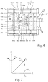
- the signals of the sensor elements can be calculated by the evaluation by means of known algorithms to forces Fx, Fy, Fz in the X, Y and Z direction of a rectangular coordinate system, as well as the occurring moments Mx, My and Mz.
- four sensor elements in the form of load cells, strain gauges or SAW elements as force sensors working at four offset by about 90 ° to each other be arranged radially from a central cylindrical hub extending spokes, the force, shape - or cohesively coupled to a carrier in the form of a measuring plate.
- This carrier in the form of a measuring plate is together with an adapter plate, with which an axially projecting area the central, cylindrical hub is positively or materially coupled, clamped between a mounting plate of a standard trailer hitch and a standard clutch carrier.
- a bias on the spokes on an axially projecting portion of the cylindrical hub can be applied by means of the Anschraubplatte a standard hitch and the standard coupling carrier expansion screws, in this carrier in the form of a measuring plate facing the clutch carrier, the spokes free, their deformation during application of the bias by means of the expansion screws enabling recesses are formed in this carrier.
- the measuring device as a module package, consisting of the mounting plate, the standard hitch, the adapter plate, designed as a measuring plate carrier and the standard coupling carrier, which are braced by means of the expansion screws against each other, attached to a fixed to the motorized vehicle standard Hitch be adjustable in height attachable.
- a fourth embodiment of a measuring device having the features of the invention is initially likewise characterized in that four sensor elements serve as force sensors and are designed as load cells, strain gauges or SAW elements, and that these sensor elements are connected to four at between 60 ° and 120 ° staggered, radially extending measuring arms of a messnchförmigen carrier are arranged.
- the messnchförmige carrier is force, form or cohesively connected to a base plate that on this messnchförmigen carrier a Screw-on plate for a standard coupling is festschraubbar, and that the base plate with a standard coupling carrier is firmly connected.
- the measuring device in addition to the necessary sensors and mounting screws on only four components, namely the messnchförmigen carrier, attachable to this carrier Anschraubplatte for a standard coupling, one on the other axial side of the carrier with this connectable base plate, as well as on the Base plate attachable coupling carrier. This will be explained on the basis of an embodiment even further.
- the messnchförmige carrier has one of its measuring arms axially projecting, directed towards the base plate central hub, which is supported on the base plate and with this force, material, or positively connected. Due to its axial length, the central, axially projecting hub provides sufficient space for the measuring arms of the measuring cross-shaped carrier to be able to deform axially freely under tensile or compressive loading of the entire apparatus by the towing vehicle or trailer vehicle or an attachment.
- axial projections are also provided at the radially outer ends of the measuring arms of the measuring cross-shaped carrier, which extend towards the mounting plate for a standard coupling and serve as axial spacers for the measuring arms relative to the mounting plate.
- this fourth embodiment of the measuring device as a module package consisting of the mounting plate for a standard hitch, the base plate, the messnchförmigen carrier and the standard coupling carrier, which are preferably interconnected by means of fastening screws, height adjustable on a fixed to the motorized vehicle standard hitch be formed attachable.
- the transmission of the signals of the sensor elements to the motorized vehicle can take place via a cable connection or wirelessly, for example by means of W-LAN. Due to the structure of the measuring device according to the invention, these can be used both on agricultural vehicles, especially farm tractors, as well as on road vehicles. The various standard hitches can be exchanged modularly, without any change to the measuring system. With the measuring device according to the invention, also the masses of the motorized vehicle and the trailer or attachment can be determined, whereby the braking effects of motorized vehicles and trailers or implements can be tuned improved.
- FIG. 1 a simplified, exploded view of the components of a measuring device 42 for measuring forces and / or moments between a motorized vehicle and a pulled or pushed therefrom, unrecognizable trailer or attachment.
- Fig. 1A a partial view of a motorized towing vehicle in the form of a tractor 1, at the rear of a box-shaped standard towing hitch 8 is screwed, as will be explained later.
- Fig. 1B schematically shows a first measuring device 42
- the support 20 is designed for sensor elements 22 in the form of a measuring plate and is screwed by means of fastening screws 25 to a Anschraubage 6 in the form of a mounting plate on the tractor 1.
- a total of four sensor elements 22 are screwed by means of sunk fastening screws 24 via intermediate mounting rails 21 on the carrier 20 designed as a measuring plate.
- the sensor elements 22 have free-standing tongues 22 a, which are festschraubt via a further pair of fastening rails 21 by means of fastening screws 23 to the standard towing bracket 8. On the freestanding tongues 22a, the sensor elements 22 are attached, which are connected wirelessly or via dotted line shown line connections with an evaluation device 40.
- the evaluation device 40 is designed at least as an electronic circuit, but preferably as a microcomputer. It can be arranged on the carrier 20 designed as a measuring plate or on the tractor 1.
- the in Fig. 1A shown in a schematic side view standard trailer hitch 8 is attached to the tractor 1 by means of a tractor mounting plate 9 on the Anschraubability 6, between which the aforementioned measuring device 42 is attached.
- the sensor elements 22 are used for force measurement and can be designed as load cells, strain gauges or SAW elements (surface acoustic wave elements).
- the in Fig. 1C illustrated box-shaped standard hitch 8 has the already mentioned tractor mounting plate 9 and the same hole pattern 10 as the mounting plate 6 on the tractor 1.
- On side walls of the standard trailer hitch 8 are parallel to each other a first locking rail 11 with a first locking groove 12 and a second locking rail 13 with a second locking groove 14 is mounted, the locking grooves 12, 14 are open facing each other.
- the two locking grooves 12, 14 holes 15 for locking means 19 in the form of locking pins are formed, for example, engage the locking pin 19 on a detent plate 18 of a standard jaw coupling 17 and fix them at a height H from the level of the ground 4.
- On a side wall of the standard trailer hitch 8, a sensor 16 for detecting the height H of the standard clutch 17 is arranged.
- a sensor element 38 which measures in a horizontal transverse plane 37 at the height H of the standard coupling 17 the angle ⁇ between a drawbar 51 of a trailer or attachment and a line passing through a central longitudinal axis of the tractor 1 in height X in the direction of the straight line.
- another sensor element 39 for measuring the angle ⁇ up or down between the drawbar 51 of a trailer or attachment and a horizontal transverse plane in the height H in the X direction is present.
- the aforementioned sensor elements 16, 38, 39 are also connected to the evaluation device 40 wirelessly or via the dotted lines shown but not further designated lines. Therefore, the evaluation device 40 can calculate by means of known algorithms both the forces Fx, Fy, Fz acting on the measuring device 20 and the corresponding moments Mx, My, Mz from the signals of the sensor elements 16, 22, 38, 39 according to size and direction and to forward a driving condition management system.
- This driving state management system can detect unstable driving situations from the signals of the sensor elements 16, 22, 38, 39 and initiate countermeasures. It is also possible, from the signals of the sensor elements 16, 22, 38, 39 make a vote of the braking effect of the tractor 1 and the trailer or the attachment.
- the driving state management system is for example designed as a computer program and stored in a separate microcomputer or in the evaluation device 40 as software.
- the measuring device 42 can be mounted as a module package between both the tractor 1 and the standard towing hitch 8 and insert with trained as a measuring plate carrier 20 in the locking grooves 12, 14 of the standard trailer hitch 8 and fix it in the mentioned height H, where a standard hitch 27 in the form of a jaw clutch according to Fig. 2E is then bolted to its support plate 20 with its mounting plate 28.
- the screw-on plate 28 of the standard hitch device 27 has a congruent standard hole pattern 28a, like the carrier 20.
- FIG. 1C visible PTO shaft 7 can be used for the drive of ancillaries only if it is not blocked by the measuring device 42.
- the measuring plate-shaped carrier 20 has a passage opening for the power take-off shaft 7.
- FIG. Fig. 2 A second embodiment of a measuring device 43 according to the invention is shown in FIG Fig. 2 represented, whose Fig. 2A shows the box-shaped standard hitch 8, which also in Fig. 1C is shown.
- This measuring device 43 has a carrier 31 in the form of a measuring plate with a standard hole pattern 31a, which is congruent to a standard hole pattern 26a of threaded holes in a standard coupling carrier 26.
- the standard clutch carrier 26 can be as already described in the locking grooves 12, 14 of the standard trailer hitch 8 insert and fix by means of locking means 19 in the form of locking pins on the standard coupling carrier 26 in the holes 15 of the standard trailer hutch 8.
- Fig. 2C can recognize the support 31 in the form of a measuring plate preferably integrally formed on this radial spoke 32, which are arranged in a plane at an angle of 90 ° to each other. Free spaces 32a are thus formed between the radial spokes 32 and the support 31 to allow the radial spokes 32 to deform in the direction of the horizontal transverse plane 37.
- the spokes 32 are connected radially inward to a central cylindrical hub 33, the axially projecting portion 33a of which is preferably adhesively bonded by means of a weld 33b to an adapter plate 35 ( Fig. 2G ).
- the carrier 31 in the form of a measuring plate has a standard hole pattern 31a which is congruent with the standard hole pattern 26a on the standard coupling carrier 26.
- a standard hole pattern 35a of the same kind also has the adapter plate 35.
- strain gauges or SAW elements are mounted as force sensors, which in the in Fig. 1 shown manner are connected to the evaluation device 40 wirelessly or via cable.
- the radio transmission of the determined measured values of the sensor elements 34 can also take place via a respective transmitter, which is connected to an antenna 52, which is arranged on the upper side of the standard coupling carrier 26.
- the carrier 31 in the form of a measuring plate, together with the adapter plate 35, with which the axially projecting portion 33a of the central cylindrical hub 33 is positively or materially coupled, between a Anschraubplatte 28 on a standard jaw clutch 27 or a Anschraubplatte 30 at one Standard ball-type coupling 29 and a standard coupling carrier 26 clamped with bias of the spokes 32.
- the bias of the spokes 32 is applied by means of between the mounting plate 28, 30 of a standard hitch 27, 29 and the standard clutch carrier 26 arranged expansion screws 36.
- the screw-on plates 28, 30 of the standard trailer coupling 27 and of the standard ball-type coupling 29 each have a congruent standard hole pattern 28a, 30a for performing expansion screws 36.
- Fig. 2G shows, in the carrier 33 in the form of a measuring plate, the spokes 32 releasing and their deformation during application of the bias voltage by means of the expansion screws 36 enabling recess or free spaces 33c educated.
- a deformation of the spokes 32 in the direction of the standard coupling carrier 26 can be caused by a force acting on the standard hitch 27 compressive force, so that these and the applied by the expansion screws 36 bias voltage by means of the sensor elements 34 can be measured.
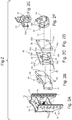
- the in the FIGS. 3 to 6 illustrated third embodiment of the measuring device 44 has a carrier 45 in the form of a measuring cross with two spaced by 60 ° or 120 ° to each other measuring arms 45a, whose free ends have eyes 45b with through holes 45d, and provided at the free ends with axial projections 45c are whose function is related to Fig. 6 is explained.
- the carrier 45 in the form of a measuring cross is provided with a central hub 46, which is substantially cylindrical, but is provided on a unilaterally axially projecting portion 46a with flats 46b.
- This axially projecting region 46a with its flattenings 46b can be inserted into a non-round recess 48c which is congruent with the hub 46 in a base plate 48, whereby the carrier 45 in the form of a measuring cross is secured against rotation with respect to the base plate 48.
- the non-circular recess 48 c of the base plate 48 terminates axially on a wall member 48 d with a central through hole 48 e for a in Fig. 3 illustrated fastening screw 49 which is screwed into a threaded bore 46c in the central hub 46 of the carrier 45 in the form of a measuring cross.
- the base plate 48 has a cylindrical depression 48a on its rear side remote from the center of the measuring instrument, into which the head of the fastening screw 49 can be lowered.
- the show FIGS. 3 and 5 clear that the base plate 48 has four through holes 48b for performing the aforementioned expansion screws 50, which are also passed through the through holes 45d of the carrier 45 and ultimately screwed into the threaded holes 26a of the standard clutch carrier 26, which in Fig. 6 is clearly recognizable.
- strain gauges or SAW elements as force sensors are respectively arranged on the measuring arms 45a and accordingly Fig. 1 wirelessly or via cable, as well as the other sensor elements, connected to the evaluation device 40.
- the measuring device 44 is as a module package from the Anschraubplatte 28, 30 of the standard hitch 27, 29, the adapter plate 35, the base plate 48, the carrier 45 in the form of a measuring cross and the standard coupling carrier 26, which are clamped by means of the expansion screws 50 against each other, at one fixed to the motorized vehicle 1 standard towing hitch 8 height adjustable attachable.
- Fig. 8 illustrated in an axial sectional view of a fourth embodiment of the features of the invention having measuring device 60 advantageously has only a very few components, which has a favorable effect on the manufacturing costs and assembly costs.
- this measuring device 60 not only the axial components of compressive and tensile forces between a towing vehicle and a hitch or attachment can measure very well, but also their spatial components.
- the measuring device 60 has a measuring cross-shaped carrier 71, which also carries four sensor elements 79, 80, which serve as force sensors and preferably designed as load cells, strain gauges or SAW elements are.
- the four sensor elements 79, 80 are arranged at four, between 60 ° and 120 ° staggered, radially extending measuring arms 74, 75 of the carrier 71, and they are as already described with an evaluation device 40 in signal connection.
- the messnchförmige carrier 71 has radially inwardly on a central hub 77, which extends axially a little way towards a base plate 63.
- the hub 77 has a non-circular geometry, with which it is received in a complementary non-circular recess 86 of the base plate 63.
- a fixing screw 70 For frictional connection of the base plate 63 with the messnchförmigen carrier 71 is a fixing screw 70, which is screwed into a threaded bore 69 of a central wall member 68 of the base plate 63 and into a threaded bore 78 of the hub 77 of the measuring cross-shaped carrier 71.
- the screw head In order to avoid an axial protrusion of this fastening screw 70, the screw head is received in a central, axial and cylindrical recess 67 of the base plate 63.
- the base plate 63 itself is firmly connected to the sensor remote side with a coupling carrier 61.
- Fixing screws 65, 66 serve this purpose, which are screwed into threaded bores 62 in the coupling carrier 61 and into threaded bores 64 in the base plate 63.
- the messnchförmige carrier 71 is fixed base plate remote with a Anschraubplatte 81 which carries a zuglanguage solution of a standard trailer hitch 27.
- the connection of the carrier 71 with this Anschraubplatte 81 is realized by means of fastening screws 84, 85 which are screwed into threaded holes 82 in the mounting plate 81 and threaded holes 76 in the radially outwardly formed eyes 72, 73 of the messnchförmigen carrier 71.
- the measuring device 60 it is provided that at the radial outer ends of the measuring arms 74, 75 of the measuring cross-shaped carrier 71 to the screw plate 81 for the standard coupling 27 facing axial projections 83 are formed on the aforementioned eyes 72, 73, which serve as spacers for the measuring arms 74, 75 relative to the screw 81.
- this measuring device 60 as a module package can be attached in a height-adjustable manner to a standard towing hanger 8 fastened to the motorized vehicle 1.
- This module package consists of the necessary sensors 79, 80 and mounting screws 65, 66, 70, 84, 85 only of the four components screw plate 81 with standard hitch 27, messnchförmiger carrier 71, base plate 48 and coupling carrier 61st
Landscapes
- Engineering & Computer Science (AREA)
- Mechanical Engineering (AREA)
- Transportation (AREA)
- Life Sciences & Earth Sciences (AREA)
- Physics & Mathematics (AREA)
- Chemical & Material Sciences (AREA)
- Soil Sciences (AREA)
- Environmental Sciences (AREA)
- General Physics & Mathematics (AREA)
- Combustion & Propulsion (AREA)
- Analytical Chemistry (AREA)
- Zoology (AREA)
- Fluid Mechanics (AREA)
- Force Measurement Appropriate To Specific Purposes (AREA)
Abstract
Die Erfindung betrifft eine Messeinrichtung (60) zum Messen von Kräften und/oder Momenten zwischen einem motorisierten Fahrzeug (1) und einem davon gezogenen oder geschobenen Anhänger oder Anbaugerät, wobei die Messeinrichtung (60) wenigstens drei an einem Träger (71) quer zu einer gedachten Längsachse des motorisierten Fahrzeugs (1) sowie zueinander beabstandet angeordnete Sensorelemente (79, 80) aufweist, wobei die Messeinrichtung (60) in einem Kupplungsbereich zwischen dem motorisierten Fahrzeug (1) und dem gezogenen oder geschobenen Anhänger oder Anbaugerät angeordnet ist, und wobei die Sensorelemente (79, 80) zur Übertragung derer Messwerte mit einem Auswertegerät (40) verbunden sind, welches dazu eingerichtet ist, diese Messwerte in Signale für Kraftanzeigen und/oder Momentenanzeigen nach Größe und Richtung umzuwandeln.The invention relates to a measuring device (60) for measuring forces and / or moments between a motorized vehicle (1) and a trailer or attachment pulled or pushed therefrom, wherein the measuring device (60) at least three on a support (71) transversely to a an imaginary longitudinal axis of the motorized vehicle (1) and mutually spaced sensor elements (79, 80), wherein the measuring device (60) is arranged in a coupling region between the motorized vehicle (1) and the towed or pushed trailer or attachment, and wherein the Sensor elements (79, 80) for transmitting these measured values are connected to an evaluation device (40) which is set up to convert these measured values into signals for force displays and / or moment displays according to size and direction.
Description
Die Erfindung betrifft eine Messeinrichtung zum Messen von Kräften und/oder Momenten zwischen einem motorisierten Fahrzeug und einem davon gezogenen oder geschobenen Anhänger oder Anbaugerät.The invention relates to a measuring device for measuring forces and / or moments between a motorized vehicle and a towed or pushed trailer or attachment thereof.
Aus der
Vor diesem Hintergrund lag der Erfindung die Aufgabe zugrunde, Koppelkräfte und Koppeldrehmomente am Kupplungspunkt zwischen einem motorisierten Fahrzeug, insbesondere einem Traktor, und einem Anhänger oder Anbaugerät während des Fahrens in drei Dimensionen zu messen, ohne dass dafür besondere Einrichtungen am Anhänger oder Anbaugerät vorgesehen werden müssen.Against this background, the present invention seeks to measure coupling forces and coupling torques at the coupling point between a motorized vehicle, in particular a tractor, and a trailer or implement during driving in three dimensions without special facilities on the trailer or attachment must be provided ,
Gelöst wird diese Aufgabe durch eine Messeinrichtung, welche die Merkmale des Anspruchs 1 aufweist. Vorteilhafte Weiterbildungen sind in den abhängigen Ansprüchen genannt.This object is achieved by a measuring device which has the features of claim 1. Advantageous developments are mentioned in the dependent claims.
Demnach betrifft die Erfindung eine Messeinrichtung zum Messen von Kräften und/oder Momenten zwischen einem motorisierten Fahrzeug und einem davon gezogenen oder geschobenen Anhänger oder Anbaugerät.Accordingly, the invention relates to a measuring device for measuring forces and / or moments between a motorized vehicle and a towed or pushed trailer or attachment.
Erfindungsgemäß ist vorgesehen, dass die Messeinrichtung wenigstens drei an einem Träger quer zu einer gedachten Längsachse des motorisierten Fahrzeugs sowie zueinander beabstandet angeordnete Sensorelemente aufweist, wobei die Messeinrichtung in einem Kupplungsbereich zwischen dem motorisierten Fahrzeug und dem gezogenen oder geschobenen Anhänger oder Anbaugerät angeordnet ist, und wobei die Sensorelemente zur Übertragung derer Messwerte mit einem Auswertegerät verbunden sind, welches dazu eingerichtet ist, diese Messwerte in Signale für Kraftanzeigen und/oder Momentenanzeigen nach Größe und Richtung umzuwandeln.According to the invention, the measuring device has at least three sensor elements arranged transversely to an imaginary longitudinal axis of the motorized vehicle and spaced from each other, wherein the measuring device is arranged in a coupling region between the motorized vehicle and the towed or pushed trailer or attachment, and wherein the sensor elements for transmitting these measured values are connected to an evaluation device, which is set up to convert these measured values into signals for force displays and / or moment displays according to size and direction.
Diese Messeinrichtung befindet sich grundsätzlich im Bereich des motorisierten Fahrzeugs, so dass an einem Anhänger oder Anbaugerät oder deren Kupplungsvorrichtungen keine Veränderungen vorgenommen zu werden brauchen. Aufgrund der in allen drei Raumkoordinaten ermittelbaren Messwerte in Form von Kräften und/oder Momenten nach Betrag und Richtung ist es in Weiterbildung der Erfindung vorgesehen, das erwähnte Auswertegerät in Datenverbindung mit einem Fahrzeugzustand-Managementsystem zu bringen, das dazu eingerichtet ist, aus den Messwerten der Sensorelemente instabile Fahrsituationen zu erkennen und Gegensteuermaßnahmen einzuleiten. Das Fahrzeugzustand-Managementsystem ist hierzu vorzugsweise als ein Mikrocomputer ausgebildet, welcher zur Durchführung von Gegensteuermaßnahmen mit einer geeigneten Software ausgestattet ist sowie mit geeigneten Aktuatoren und/oder elektromagnetischen Steuerventilen zur Betätigung derselben verbunden ist.This measuring device is basically in the range of the motorized vehicle, so that no changes need to be made to a trailer or attachment or their coupling devices. On the basis of the measured values ascertainable in all three spatial coordinates in the form of forces and / or moments according to amount and direction, it is provided in a further development of the invention to bring the mentioned evaluation device into data connection with a vehicle state management system which is set up from the measured values Sensor elements to detect unstable driving situations and initiate countermeasures. The vehicle state management system is for this purpose preferably designed as a microcomputer, which is equipped to carry out countermeasures with appropriate software and is connected to suitable actuators and / or electromagnetic control valves for operating the same.
Des Weiteren ist das Fahrzeugzustand-Managementsystem in Weiterbildung der Erfindung so eingerichtet, dass es in der Lage ist, aus den Messwerten der Sensorelemente Steuersignale für Aktuatoren zur Bewirkung einer Abstimmung der Bremswirkung des motorisierten Fahrzeugs und des Anhängers oder des Anhängegeräts aufeinander zu erzeugen.Furthermore, the vehicle state management system in a development of the invention is set up in such a way that it is able to generate control signals for actuators from the measured values of the sensor elements to effect a coordination of the braking effect of the motorized vehicle and of the trailer or of the towing device.
Gemäß einer vorteilhaften Weiterbildung einer die Merkmale der Erfindung aufweisenden Messeinrichtung ist vorgesehen, dass die Messeinrichtung als Modulpaket zwischen einer Anschraubaufnahme am motorisierten Fahrzeug für einen Standard-Anhängebock und diesem Standard-Anhängebock montiert ist, und dass eine Standard-Anhängevorrichtung, wie etwa eine Standard-Maulkupplung oder eine Standard-Kugelkopfkupplung, direkt am Standard-Anhängebock befestigt ist.According to an advantageous development of a measuring device having the features of the invention, it is provided that the measuring device is mounted as a module package between a bolt-on receptacle on the motorized vehicle for a standard towing hitch and this standard towing hitch, and that a standard hitch, such as a standard hitch Maulkupplung or a standard ball coupling, directly on the standard towing hitch is attached.
Vorzugsweise ist diese Standard-Anhängevorrichtung am Standard-Anhängebock lösbar und höhenverstellbar befestigt.This standard towing device is preferably detachable and height-adjustable on the standard towing hitch.
Außerdem ist es bevorzugt vorgesehen, dass die Messeinrichtung als Modulpaket an einem Standard-Anhängebock am motorisierten Fahrzeug montierbar ist sowie mittels eines am Standard-Anhängebock angeordneten Kupplungsträgers mit einer Standard-Anhängevorrichtung, wie etwa eine Standard-Maulkupplung oder eine Standard-Kugelkopfkupplung, verschraubt ist.In addition, it is preferably provided that the measuring device can be mounted as a modular package on a standard towing bracket on the motorized vehicle and by means of a standard hitch on the coupling support with a standard hitch, such as a standard jaw coupling or a standard ball coupling is screwed ,
Besonders vorteilhaft ist es, wenn auch der Kupplungsträger am Standard-Anhängebock lösbar und höhenverstellbar befestigt ist.It is particularly advantageous if the coupling carrier is fastened on the standard towing hanger in a detachable and height-adjustable manner.
Die erfindungsgemäße Messeinrichtung kann vorteilhafterweise derartig aufgebaut sein, dass vier Sensorelemente als Kraftsensoren dienen sowie als Wägezellen, Dehnungsmessstreifen oder SAW-Elemente (Surface-Acoustic-Wave-Element) ausgebildet sind, dass die vier Sensorelemente an vier um etwa zwischen 60° und 120° gegeneinander versetzten, sich radial erstreckenden Messarmen eines messkreuzförmigen Trägers angeordnet sind, dass der messkreuzförmige Träger kraft-, form- oder stoffschlüssig an eine Basisplatte gekoppelt ist, und dass der messkreuzförmige Träger zwischen der Basisplatte und einem Standard-Kupplungsträger eingespannt ist.The measuring device according to the invention can advantageously be constructed in such a way that four sensor elements serve as force sensors and are designed as load cells, strain gauges or SAW elements (surface acoustic wave element) such that the four sensor elements at four are approximately between 60 ° and 120 ° offset from one another, are arranged radially extending measuring arms of a messkreuzförmigen carrier, that the messkreuzförmige carrier is positively, positively or materially coupled to a base plate, and that the messkreuzförmige carrier is clamped between the base plate and a standard coupling carrier.
Weiter ist bevorzugt vorgesehen, dass eine Vorspannung auf Messarme des messkreuzförmigen Trägers mittels zwischen einer Anschraubplatte einer Standard-Anhängekupplung und einem Standard-Kupplungsträger angeordneten Dehnschrauben aufgebracht ist.Further, it is preferably provided that a bias on measuring arms of the measuring cross-shaped carrier by means of between a mounting plate of a standard trailer coupling and a standard clutch carrier arranged expansion screws is applied.
Hierbei ist es vorteilhaft, wenn vorgesehen ist, dass der messkreuzförmige Träger eine von seinen Messarmen axial vorstehende, zur Basisplatte gerichtete, zentrale Nabe aufweist, welche sich an der Basisplatte abstützt und mit dieser kraft-, stoff-, oder formschlüssig gekoppelt ist. Hierdurch lassen sich an dem messkreuzförmigen Träger zwar nur Zugkräfte übertragen, die beim Ziehen eines Anhängers oder eines Anbaugeräts auftreten, also keine Druckkräfte, wie sie beim Schieben eines Anhängers oder eines Anbaugeräts auftreten können.It is advantageous if it is provided that the messkreuzförmige carrier has one of its measuring arms axially projecting, directed towards the base plate, central hub, which is supported on the base plate and with this force, material, or positively coupled. As a result, only tensile forces that occur when pulling a trailer or an attachment, so no pressure forces, as they can occur when pushing a trailer or an attachment can be transmitted to the messkreuzförmigen carrier.
Um auch diese Druckkräfte messen zu können, kann vorgesehen sein, dass an den radial äußeren Enden der Messarme des messkreuzförmigen Trägers zum Standard-Kupplungsträger gewandte axiale Vorsprünge als Abstandshalter für die Messarme gegenüber dem Standard-Kupplungsträger ausgebildet sind. Dadurch lassen sich die Messarme des messkreuzförmigen Trägers axial in beide Richtungen durch Zug- und Druckkräfte bewegen und es werden dabei dessen Messarme entsprechend verformt, so dass sich dreidimensionale Werte für die Ermittlung der Zug- und Drucckräfte sowie der auf den Traktor wirkenden Momente berechnen lassen.In order to measure these compressive forces, it can be provided that at the radially outer ends of the measuring arms of the measuring cross-shaped carrier to the standard coupling carrier facing axial projections are designed as spacers for the measuring arms relative to the standard coupling carrier. As a result, the measuring arms of the measuring cross-shaped carrier can be moved axially in both directions by tensile and compressive forces and its measuring arms are correspondingly deformed, so that three-dimensional values for determining the tensile and compressive forces as well as the moments acting on the tractor can be calculated.
Eine konstruktiv vorteilhafte Ausführungsform der zentralen Nabe besteht darin, dass ein axial vorstehender Bereich der zentralen Nabe in eine Vertiefung in der Basisplatte eingreift und darin mittels einer eine Bohrung in einem Wandelement der Basisplatte durchgreifende Befestigungsschraube befestigt ist. Der in die Vertiefung der Basisplatte eingreifende, axial vorstehende Bereich der zentralen Nabe kann als Verdrehsicherung unrund ausgeführt sein, also beispielsweise Anflächungen aufweisen, wofür dann die Vertiefung, in die der axial vorstehende Bereich der zentralen Nabe eingreift, entsprechend geometrisch ergänzend geformt ist.A structurally advantageous embodiment of the central hub is that an axially projecting portion of the central hub engages in a recess in the base plate and is secured therein by means of a fastening screw passing through a bore in a wall element of the base plate. The engaging in the recess of the base plate, axially projecting portion of the central hub may be designed as rotation non-round, so for example, have flats, what then the recess, in which engages the axially projecting portion of the central hub, is geometrically complementarily shaped.
Vorteilhafterweise lässt sich die Messeinrichtung als Modulpaket, gebildet aus der Anschraubplatte, der Standard-Anhängevorrichtung, der Adapterplatte, der Basisplatte, dem messkreuzförmigen Träger und dem Standard-Kupplungsträger, die mittels der Dehnschrauben gegeneinander verspannt sind, an einem am motorisierten Fahrzeug befestigten Standard-Anhängebock höhenverstellbar anbringen.Advantageously, the measuring device can be as a module package, formed from the mounting plate, the standard hitch, the adapter plate, the base plate, the messkreuzförmigen carrier and the standard coupling carrier by means of the expansion bolts are braced against each other, attach height adjustable on a standard towing hitch attached to the motorized vehicle.
Insbesondere kann die Messeinrichtung als Modulpaket an einem Standard-Anhängebock am motorisierten Fahrzeug montierbar ausgebildet sein und mittels eines am Standard-Anhängebock angeordneten Kupplungsträgers mit einer Standard-Anhängevorrichtung, wie Maulkupplung oder Kugelkopfkupplung, verschraubt sein. Besonders bevorzugt ist es, wenn der Kupplungsträger am Standard-Anhängebock lösbar und höhenverstellbar befestigt ist.In particular, the measuring device can be designed to be mountable as a modular package on a standard towing lug on the motorized vehicle and bolted by means of a standard hitch on the coupling carrier with a standard hitch, such as jaw or ball coupling. It is particularly preferred if the coupling carrier is fastened to the standard towing hanger in a detachable and height-adjustable manner.
Durch die Wirkverbindung zwischen dem Standard-Anhängebock und der Basisplatte werden die Sensorelemente mit den Messarmen des messkreuzförmigen Trägers durch die Last des gezogenen oder geschobenen Anhängers oder des Anbaugeräts, abhängig von der Größe und der Richtung der Beanspruchungen des Standard-Anhängebocks verformt. Die Signale der Sensorelemente lassen sich durch das Auswertegerät mittels bekannter Algorithmen zu Kräften Fx, Fy, Fz in X-, Y- und Z-Richtung eines rechtwinkligen Koordinatensystems berechnen, ebenso die auftretenden Momente Mx, My und Mz. Diese Kräfte und Momente sind abhängig von der Höhe H der Standard-Anhängevorrichtung vom Niveau des Erdbodens und von einem Winkel α, den eine Deichsel eines Anhängers oder eines Anbaugeräts in einer waagerechten Querebene gegenüber dem motorisierten Fahrzeug einnimmt, und ebenso von einem Winkel β, den die Deichsel des Anhängers oder des Anbaugeräts gegenüber der waagerechten Querebene des motorisierten Fahrzeugs nach oben oder unten einnimmt.The operative connection between the standard hitch and the base plate deforms the sensor elements with the measuring arms of the chevron-shaped carrier by the load of the towed trailer or implement, depending on the size and direction of the standard hanger loads. The signals of the sensor elements can be calculated by the evaluation by means of known algorithms to forces Fx, Fy, Fz in the X, Y and Z direction of a rectangular coordinate system, as well as the occurring moments Mx, My and Mz. These forces and moments are dependent from the height H of the standard hitch from the ground level and from an angle α taken by a tiller of a trailer or implement in a horizontal transverse plane with respect to the motorized vehicle, and also from an angle β between the tiller of the trailer or the trailer Attachment opposite the horizontal transverse plane of the motor vehicle takes up or down.
Gemäß einer zweiten vorteilhaften Ausführungsform der erfindungsgemäßen Messeinrichtung können vier Sensorelemente in Form von Wägezellen, Dehnungsmessstreifen oder SAW-Elementen als Kraftsensoren arbeitend an vier um etwa 90° gegeneinander versetzten, sich radial von einer zentralen zylindrischen Nabe erstreckenden Speichen angeordnet sein, die kraft-, form- oder stoffschlüssig mit einem Träger in Form einer Messplatte gekoppelt sind. Dieser Träger in Form einer Messplatte ist zusammen mit einer Adapterplatte, mit welcher ein axial vorstehender Bereich der zentralen, zylindrischen Nabe form- oder stoffschlüssig gekoppelt ist, zwischen einer Anschraubplatte einer Standard-Anhängekupplung und einem Standard-Kupplungsträger eingespannt.According to a second advantageous embodiment of the measuring device according to the invention, four sensor elements in the form of load cells, strain gauges or SAW elements as force sensors working at four offset by about 90 ° to each other, be arranged radially from a central cylindrical hub extending spokes, the force, shape - or cohesively coupled to a carrier in the form of a measuring plate. This carrier in the form of a measuring plate is together with an adapter plate, with which an axially projecting area the central, cylindrical hub is positively or materially coupled, clamped between a mounting plate of a standard trailer hitch and a standard clutch carrier.
Hierbei kann eine Vorspannung auf die Speichen über einen axial vorstehenden Bereich der zylindrischen Nabe mittels zwischen der Anschraubplatte einer Standard-Anhängekupplung und dem Standard-Kupplungsträger angeordneten Dehnschrauben aufgebracht werden, wobei in diesem Träger in Form einer Messplatte dem Kupplungsträger zugewandte, die Speichen frei gebende, deren Verformung beim Aufbringen der Vorspannung mittels der Dehnschrauben ermöglichende Ausnehmungen in diesem Träger ausgebildet sind.In this case, a bias on the spokes on an axially projecting portion of the cylindrical hub can be applied by means of the Anschraubplatte a standard hitch and the standard coupling carrier expansion screws, in this carrier in the form of a measuring plate facing the clutch carrier, the spokes free, their deformation during application of the bias by means of the expansion screws enabling recesses are formed in this carrier.
Auch in diesem Fall kann die Messeinrichtung als Modulpaket, bestehend aus der Anschraubplatte, der Standard-Anhängevorrichtung, der Adapterplatte, dem als Messplatte ausgebildeten Träger sowie dem Standard-Kupplungsträger, die mittels der Dehnschrauben gegeneinander verspannt sind, an einem am motorisierten Fahrzeug befestigten Standard-Anhängebock höhenverstellbar anbringbar ausgebildet sein.Also in this case, the measuring device as a module package, consisting of the mounting plate, the standard hitch, the adapter plate, designed as a measuring plate carrier and the standard coupling carrier, which are braced by means of the expansion screws against each other, attached to a fixed to the motorized vehicle standard Hitch be adjustable in height attachable.
Eine sich bei durchgeführten Untersuchungen als besonders vorteilhaft gezeigte vierte Ausführungsform einer die Merkmale der Erfindung aufweisenden Messeinrichtung ist zunächst ebenfalls dadurch gekennzeichnet, dass vier Sensorelemente als Kraftsensoren dienen sowie als Wägezellen, Dehnungsmessstreifen oder SAW-Elemente ausgebildet sind, und dass diese Sensorelemente an vier um zwischen 60° und 120° gegeneinander versetzten, sich radial erstreckenden Messarmen eines messkreuzförmigen Trägers angeordnet sind. Zur Reduzierung des Bauteil- und Montageaufwandes sowie zur Erzielung besonders vorteilhafter Messergebnisse hinsichtlich der Richtung der auftretenden und zu messenden Kräfte ist jedoch zusätzlich vorgesehen, dass der messkreuzförmige Träger kraft-, form- oder stoffschlüssig mit einer Basisplatte verbunden ist, dass an diesem messkreuzförmigen Träger eine Anschraubplatte für eine Standard-Kupplung festschraubbar ist, und dass die Basisplatte mit einen Standard-Kupplungsträger fest verbindbar ist.A fourth embodiment of a measuring device having the features of the invention, which has been found to be particularly advantageous in tests carried out, is initially likewise characterized in that four sensor elements serve as force sensors and are designed as load cells, strain gauges or SAW elements, and that these sensor elements are connected to four at between 60 ° and 120 ° staggered, radially extending measuring arms of a messkreuzförmigen carrier are arranged. To reduce the component and assembly costs and to achieve particularly advantageous measurement results in terms of the direction of the forces occurring and to be measured, however, additionally provided that the messkreuzförmige carrier is force, form or cohesively connected to a base plate that on this messkreuzförmigen carrier a Screw-on plate for a standard coupling is festschraubbar, and that the base plate with a standard coupling carrier is firmly connected.
Durch diese Konstruktion weist die Messvorrichtung neben den notwendigen Sensoren und Befestigungsschrauben nur vier Bauteile auf, nämlich den messkreuzförmigen Träger, eine an diesem Träger befestigbare Anschraubplatte für eine Standard-Kupplung, eine an der anderen Axialseite des Trägers mit diesem verbindbare Basisplatte, sowie einen an der Basisplatte befestigbaren Kupplungsträger. Dies wird anhand eines Ausführungsbeispiels noch weiter erläutert.By this construction, the measuring device in addition to the necessary sensors and mounting screws on only four components, namely the messkreuzförmigen carrier, attachable to this carrier Anschraubplatte for a standard coupling, one on the other axial side of the carrier with this connectable base plate, as well as on the Base plate attachable coupling carrier. This will be explained on the basis of an embodiment even further.
In Weiterbildung dieser besonders günstigen Konstruktion ist bevorzugt vorgesehen, dass der messkreuzförmige Träger eine von seinen Messarmen axial vorstehende, zur Basisplatte gerichtete zentrale Nabe aufweist, welche sich an der Basisplatte abstützt und mit dieser kraft-, stoff-, oder formschlüssig verbunden ist. Die zentrale, axial vorstehende Nabe schafft aufgrund ihrer axialen Länge ausreichend Platz, damit sich die Messarme des messkreuzförmigen Trägers bei einer Zug- oder Druckbelastung der Gesamtvorrichtung durch das Zugfahrzeug oder das Anhängefahrzeug beziehungsweise eines Anbaugeräts axial frei verformen können.In development of this particularly favorable construction is preferably provided that the messkreuzförmige carrier has one of its measuring arms axially projecting, directed towards the base plate central hub, which is supported on the base plate and with this force, material, or positively connected. Due to its axial length, the central, axially projecting hub provides sufficient space for the measuring arms of the measuring cross-shaped carrier to be able to deform axially freely under tensile or compressive loading of the entire apparatus by the towing vehicle or trailer vehicle or an attachment.
Hierzu sind auch axiale Vorsprünge an den radial äußeren Enden der Messarme des messkreuzförmigen Trägers vorgesehen, welche sich hin zur Anschraubplatte für eine Standard-Kupplung erstecken und als axiale Abstandshalter für die Messarme gegenüber der Anschraubplatte dienen.For this purpose, axial projections are also provided at the radially outer ends of the measuring arms of the measuring cross-shaped carrier, which extend towards the mounting plate for a standard coupling and serve as axial spacers for the measuring arms relative to the mounting plate.
Schließlich kann auch diese vierte Ausführungsform der Messeinrichtung als Modulpaket bestehend aus der Anschraubplatte für eine Standard-Anhängevorrichtung, der Basisplatte, dem messkreuzförmigen Träger und dem Standard-Kupplungsträger, welche vorzugsweise mittels Befestigungsschrauben miteinander verbunden sind, an einem am motorisierten Fahrzeug befestigten Standard-Anhängebock höhenverstellbar anbringbar ausgebildet sein.Finally, this fourth embodiment of the measuring device as a module package consisting of the mounting plate for a standard hitch, the base plate, the messkreuzförmigen carrier and the standard coupling carrier, which are preferably interconnected by means of fastening screws, height adjustable on a fixed to the motorized vehicle standard hitch be formed attachable.
Es ist ersichtlich, dass an einem Standard-Anhängebock unterschiedliche Standard-Anhängevorrichtungen angebracht werden können, die sich durch das geschilderte vertikale Führungssystem am Anhängebock in ihrer Höhe einstellen lassen.It can be seen that a standard towing hitch different standard hitches can be attached, which can be adjusted by the described vertical guide system on the towing hitch in height.
Die Übertragung der Signale der Sensorelemente zum motorisierten Fahrzeug kann über eine Kabelverbindung oder drahtlos, beispielsweise mittels W-LAN, erfolgen. Aufgrund des Aufbaus der erfindungsgemäßen Messeinrichtung lässt sich diese sowohl an landwirtschaftlichen Fahrzeugen, insbesondere Ackerschlepper, als auch an Straßenfahrzeugen verwenden. Die verschiedenen Standard-Anhängevorrichtungen lassen sich modular austauschen, ohne dass an der Messeinrichtung etwas zu ändern wäre. Mit der erfindungsgemäßen Messeinrichtung lassen sich auch die Massen des motorisierten Fahrzeugs und des Anhängers oder Anbaugeräts bestimmen, wodurch sich die Bremswirkungen von motorisierten Fahrzeugen und Anhänger oder Anbaugeräten verbessert abstimmen lassen.The transmission of the signals of the sensor elements to the motorized vehicle can take place via a cable connection or wirelessly, for example by means of W-LAN. Due to the structure of the measuring device according to the invention, these can be used both on agricultural vehicles, especially farm tractors, as well as on road vehicles. The various standard hitches can be exchanged modularly, without any change to the measuring system. With the measuring device according to the invention, also the masses of the motorized vehicle and the trailer or attachment can be determined, whereby the braking effects of motorized vehicles and trailers or implements can be tuned improved.
Die Erfindung wird nachstehend anhand mehrerer, in der beigefügten Zeichnung dargestellter Ausführungsbeispiele weiter erläutert. In der Zeichnung zeigt
-
Fig. 1 eine vereinfachte, auseinander gezogene Darstellung der Bauteile einer Messeinrichtung zum Messen von Kräften und/oder Momenten zwischen einem motorisierten Fahrzeug und einem davon gezogenen oder geschobenen Anhänger oder Anbaugerät, wovon -
Fig. 1A eine teilweise Ansicht eines motorisierten Fahrzeugs in Form eines Traktors mit einer schematischen Seitenansicht der Messeinrichtung gemäßFig. 1 zeigt, -
Fig. 1B eine auseinander gezogene isometrische Darstellung der Messeinrichtung gemäßFig. 1A zeigt, -
Fig. 1C eine isometrische Darstellung eines kastenförmigen Standard-Anhängebocks für einen Traktor zeigt, -
Fig. 1D eine schematische isometrische Darstellung einer Standard-Anhängevorrichtung in Form einer Maulkupplung zeigt, und bei der -
Fig. 2 eine vereinfachte, auseinander gezogene isometrische Darstellung der Bauelemente einer erfindungsgemäßen Messeinrichtung gemäß einer zweiten Ausführungsform zeigt, wovon, -
Fig. 2A eine isometrische Darstellung eines kastenförmigen Standard-Anhängebocks für einen Traktor zeigt, -
Fig. 2B eine isometrische Darstellung eines Standard-Kupplungsträgers mit Verriegelungsmitteln zeigt, -
Fig. 2C eine isometrische Darstellung einer Messeinrichtung an einem Träger in Form einer Messplatte mit einer Speichenradgeometrie gemäßFig. 2 zeigt, -
Fig. 2D eine isometrische Darstellung einer Adapterplatte zeigt, -
Fig. 2E eine isometrische Darstellung einer Standard-Maulkupplung mit Standard-Anschraubplatte zeigt, -
Fig. 2F eine dazu alternative isometrische Darstellung einer Standard-Kugelkopfkupplung mit Anschraubplatte zeigt, -
Fig. 2G eine Schnittansicht der Messeinrichtung gemäßFig. 2A mit den Elementen gemäß denFiguren 2B bis 2E zeigt, und bei der -
Fig. 3 eine isometrische Darstellung einer erfindungsgemäßen Messeinrichtung mit einem messkreuzförmigen Träger gemäßFig. 4 zeigt, -
Fig. 4 eine isometrische Darstellung eines mit einer Basisplatte zu verspannenden messkreuzförmigen Träger gemäßFig. 3 zeigt, -
Fig. 5 eine isometrische Rückansicht der Basisplatte gemäßFig. 4 zeigt, -
Fig. 6 eine Schnittansicht der zusammengebauten Messeinrichtung gemäß denFiguren 3 bis 5 zeigt, -
Fig. 7 ein rechtwinkliges, dreidimensionales Koordinatenkreuz mit eingezeichneten Kräften Fx, Fy, Fz und Momenten Mx, My, Mz zeigt, und -
Fig. 8 eine axiale Schnittansicht der zusammengebauten Messeinrichtung ähnlich der gemäßFig. 6 zeigt.
-
Fig. 1 a simplified, exploded view of the components of a measuring device for measuring forces and / or moments between a motorized vehicle and a towed or pushed trailer or attachment thereof, of which -
Fig. 1A a partial view of a motorized vehicle in the form of a tractor with a schematic side view of the measuring device according toFig. 1 shows, -
Fig. 1B an exploded isometric view of the measuring device according toFig. 1A shows, -
Fig. 1C shows an isometric view of a box-shaped standard trailer hitch for a tractor, -
Fig. 1D a schematic isometric view of a standard hitch in the form of a jaw clutch shows, and in the -
Fig. 2 2 shows a simplified, exploded isometric view of the components of a measuring device according to the invention according to a second embodiment, of which -
Fig. 2A shows an isometric view of a box-shaped standard trailer hitch for a tractor, -
Fig. 2B shows an isometric view of a standard coupling carrier with locking means, -
Fig. 2C an isometric view of a measuring device on a support in the form of a measuring plate with a Speichenradgeometrie according toFig. 2 shows, -
Fig. 2D shows an isometric view of an adapter plate, -
Fig. 2E shows an isometric view of a standard jaw coupling with standard mounting plate, -
Fig. 2F an alternative isometric view of a standard ball and socket coupling with mounting plate, -
Fig. 2G a sectional view of the measuring device according toFig. 2A with the elements according to theFigures 2B to 2E shows, and at the -
Fig. 3 an isometric view of a measuring device according to the invention with a messkreuzförmigen carrier according toFig. 4 shows, -
Fig. 4 an isometric view of a with a base plate to be clamped messkreuzförmigen carrier according toFig. 3 shows, -
Fig. 5 an isometric rear view of the base plate according toFig. 4 shows, -
Fig. 6 a sectional view of the assembled measuring device according to theFIGS. 3 to 5 shows, -
Fig. 7 shows a right-angled, three-dimensional coordinate system with indicated forces Fx, Fy, Fz and moments Mx, My, Mz, and -
Fig. 8 an axial sectional view of the assembled measuring device similar to that according toFig. 6 shows.
Demnach zeigt
Die Sensorelemente 22 weisen freistehende Zungen 22a auf, die über ein weiteres Paar Befestigungsschienen 21 mittels Befestigungsschrauben 23 an dem Standard-Anhängebock 8 festschraubt sind. An den freistehenden Zungen 22a sind die Sensorelemente 22 angebracht, die drahtlos oder über mit gepunkteter Line dargestellte Leitungsverbindungen mit einem Auswertegerät 40 verbunden sind. Das Auswertegerät 40 ist zumindest als eine elektronische Schaltung, jedoch vorzugsweise als Mikrocomputer ausgebildet. Es kann an dem als Messplatte ausgebildeten Träger 20 oder am Traktor 1 angeordnet sein.The
In einer Raddrehachse 3 des Hinterrades 2 des Traktors 1 ist der Nullpunkt eines rechtwinkligen, dreiachsigen Koordinatensystems mit Koordinatenachsen X, Y, Z eingezeichnet, wobei die Z -Achse durch einen Radaufstandspunkt 5 des Hinterrades 2 auf dem Niveau des Erdbodens 4 verläuft.In a Raddrehachse 3 of the
Der in
Der in
Des Weiteren ist gemäß
Die genannten Sensorelemente 16, 38, 39 sind ebenfalls drahtlos oder über die mit gepunkteter Line dargestellten aber nicht weiter bezeichneten Leitungen mit dem Auswertegerät 40 verbunden. Daher kann das Auswertegerät 40 mittels bekannter Algorithmen sowohl die auf die Messeinrichtung 20 einwirkenden Kräfte Fx, Fy, Fz als auch die entsprechenden Momente Mx, My, Mz aus den Signalen der Sensorelemente 16, 22, 38, 39 nach Größe und Richtung berechnen sowie an ein Fahrzustand-Managementsystem weiterleiten. Dieses Fahrzustand-Managementsystem kann aus den Signalen der Sensorelemente 16, 22, 38, 39 instabile Fahrsituationen ableitend erkennen und Gegensteuermaßnahmen einleiten. Ebenso ist es möglich, aus den Signalen der Sensorelemente 16, 22, 38, 39 eine Abstimmung der Bremswirkung des Traktors 1 und des Anhängers oder des Anbaugeräts vorzunehmen. Das Fahrzustand-Managementsystem ist beispielswiese als ein Computerprogramm ausgebildet und in einem gesonderten Mikrocomputer oder in dem Auswertegerät 40 als Software abgespeichert.The
Die Messeinrichtung 42 lässt sich als Modulpaket sowohl zwischen dem Traktor 1 und dem Standard-Anhängebock 8 montieren als auch mit dem als Messplatte ausgebildeten Träger 20 in die Rastnuten 12, 14 des Standard-Anhängebocks 8 einschieben und darin in der erwähnten Höhe H fixieren, wobei eine Standard-Anhängevorrichtung 27 in Form einer Maulkupplung gemäß
Eine in
Eine zweite Ausführungsform einer erfindungsgemäßen Messeinrichtung 43 ist in
Wie
Die Speichen 32 sind radial innen mit einer zentralen zylindrischen Nabe 33 verbunden, deren axial vorstehender Bereich 33a vorzugsweise mittels einer Schweißnaht 33b mit einer Adapterplatte 35 stoffschlüssig verbunden ist (
An den radialen Speichen 32 sind Sensorelemente 34 in Form von Wägezellen, Dehnungsmessstreifen oder SAW-Elementen als Kraftsensoren angebracht, die in der in
Der Träger 31 in Form einer Messplatte ist zusammen mit der Adapterplatte 35, mit welcher der axial vorstehender Bereich 33a der zentralen, zylindrischen Nabe 33 form- oder stoffschlüssig gekoppelt ist, zwischen einer Anschraubplatte 28 an einer Standard-Maulkupplung 27 oder einer Anschraubplatte 30 an einer Standard-Kugelkopfkupplung 29 und einem Standard-Kupplungsträger 26 mit Vorspannung der Speichen 32 eingespannt.The
Die Vorspannung der Speichen 32 wird mittels zwischen der Anschraubplatte 28, 30 einer Standard-Anhängekupplung 27, 29 und dem Standard-Kupplungsträger 26 angeordneten Dehnschrauben 36 aufgebracht. Die Anschraubplatten 28, 30 der Standard-Anhängekupplung 27 und der Standard-Kugelkopfkupplung 29 weisen hierzu jeweils ein kongruentes Standard-Lochschema 28a, 30a zum Durchführen von Dehnschrauben 36 auf.The bias of the
Wie
Umgekehrt wird durch eine auf die Standard-Anhängekupplung 27 aufgebrachte Zugkraft eine Bewegung der Adapterplatte 35 und damit der zentralen, zylindrischen Nabe 33a hervorgerufen. Dies bewirkt eine entsprechende Entspannung der radialen Speichen 32, die ebenfalls mittels der Sensorelemente 34 erfassbar ist und aufgrund der um 90° versetzten Anordnung der vier radialen Speichen 32 Signale ergibt, welche zusammen betrachtet durch einen entsprechenden Algorithmus des Auswertegeräts 40 Werte für die aufgebrachten Kräfte Fx, Fx, Fz in X-, Y-, Z-Richtung sowie die entsprechenden Momente Mx, My, Mz ergibt, wie dies in
Die in den
Auf ihrer messkreuzfernen Rückseite weist die Basisplatte 48 eine zylindrische Vertiefung 48a auf, in welche der Kopf der Befestigungsschraube 49 versenkbar ist. Außerdem zeigen die
Zwischen den Augen 45b an den freien Enden der vier Messarme 45a und der zentralen Nabe 46 des Trägers 45 sind an den Messarmen 45a jeweils Sensorelemente 47 in Form von Wägezellen, Dehnungsmessstreifen oder SAW-Elementen als Kraftsensoren angeordnet sowie entsprechend
Auch die Messeinrichtung 44 gemäß den
Die in
Hierzu weist die Messvorrichtung 60 einen messkreuzförmigen Träger 71 auf, welcher ebenfalls vier Sensorelemente 79, 80 trägt, die als Kraftsensoren dienen sowie bevorzugt als Wägezellen, Dehnungsmessstreifen oder SAW-Elemente ausgebildet sind. Die vier Sensorelemente 79, 80 sind an vier um zwischen 60° und 120° gegeneinander versetzten, sich radial erstreckenden Messarmen 74, 75 des Trägers 71 angeordnet, und sie stehen wie schon geschildert mit einem Auswertegerät 40 in Signalverbindung. Der messkreuzförmige Träger 71 weist radial innen eine zentrale Nabe 77 auf, welche sich axial ein Stück weit hin zu einer Basisplatte 63 erstreckt. Die Nabe 77 weist eine unrunde Geometrie auf, mit der sie in einer dazu komplementären unrunden Vertiefung 86 der Basisplatte 63 aufgenommen ist. Hierdurch ist eine Verdrehsicherung geschaffen. Zur kraftschlüssigen Verbindung der Basisplatte 63 mit dem messkreuzförmigen Träger 71 dient eine Befestigungsschraube 70, welche in eine Gewindebohrung 69 eines zentrischen Wandelements 68 der Basisplatte 63 und in eine Gewindebohrung 78 der Nabe 77 des messkreuzförmigen Trägers 71 eingeschraubt ist. Um ein axiales Hervorstehen dieser Befestigungsschraube 70 zu vermeiden, ist deren Schraubenkopf in einer zentrischen, axialen und zylindrischen Vertiefung 67 der Basisplatte 63 aufgenommen.For this purpose, the measuring
Die Basisplatte 63 selbst ist an deren sensorfernen Seite mit einem Kupplungsträger 61 fest verbunden. Hierzu dienen Befestigungsschrauben 65, 66, welche in Gewindebohrungen 62 in dem Kupplungsträger 61 und in Gewindebohrungen 64 in der Basisplatte 63 eingeschraubt sind.The
Der messkreuzförmige Träger 71 ist basisplattenfern mit einer Anschraubplatte 81 fest verbunden, welche einen zugfahrzeugseitigen Teil einer Standard-Anhängerkupplung 27 trägt. Die Verbindung des Trägers 71 mit dieser Anschraubplatte 81 ist mittels Befestigungsschrauben 84, 85 realisiert, welche in Gewindebohrungen 82 in der Anschraubplatte 81 und in Gewindebohrungen 76 in den radial außen ausgebildeten Augen 72, 73 des messkreuzförmigen Trägers 71 eingeschraubt sind.The
Auch bei dieser Ausführungsform der erfindungsgemäßen Messeinrichtung 60 ist vorgesehen, dass an den radialen äußeren Enden der Messarme 74, 75 des messkreuzförmigen Trägers 71 zur Anschraubplatte 81 für die Standard-Kupplung 27 gewandte axiale Vorsprünge 83 an den erwähnten Augen 72, 73 ausgebildet sind, welche als Abstandshalter für die Messarme 74, 75 gegenüber dem Anschraubplatte 81 dienen.Also in this embodiment of the measuring
Die
- 11
- Motorisiertes Fahrzeug (Traktor)Motorized vehicle (tractor)
- 22
- Hinterradrear wheel
- 33
- Raddrehachsewheel rotation
- 44
- Niveau des ErdbodensLevel of the soil
- 55
- Radaufstandspunktwheel contact
- 66
- Anschraubaufnahme (Befestigungsplatte am Traktor)Screw-on mounting (mounting plate on the tractor)
- 77
- ZapfwellePTO
- 88th
- Standard-Anhängebock, kastenförmigStandard towing hitch, box-shaped
- 99
- Traktorbefestigungsplatte am AnhängebockTractor mounting plate on the trailer hitch
- 1010
- Bohrungsschema am Standard-AnhängebockBore pattern on the standard towing hitch
- 1111
- Erste Rastschiene am Standard-AnhängebockFirst snap-in rail on the standard towing hitch
- 1212
- Erste RastnutFirst detent groove
- 1313
- Zweite Rastschiene am Standard-AnhängebockSecond locking rail on standard towing hitch
- 1414
- Zweite RastnutSecond locking groove
- 1515
- Bohrungen für Verriegelungsmittel in RastschieneHoles for locking means in locking rail
- 1616
- Sensorelement zum Erkennen der Kupplungshöhe HSensor element for detecting the coupling height H
- 1717
- Standard-MaulkupplungStandard bar coupling
- 1818
- Rastplatte an der MaulkupplungDetent plate on the jaw clutch
- 1919
- Verriegelungsmittel (Rastzapfen)Locking means (locking pin)
- 2020
- Träger in Form einer MessplatteCarrier in the form of a measuring plate
- 2121
- Befestigungsschienenfixing rails
- 2222
- Sensorelementesensor elements
- 22a22a
-
Freistehende Zungen der Sensorelemente 22Freestanding tongues of the
sensor elements 22 - 2323
- Befestigungsschraubenmounting screws
- 2424
- Versenkte BefestigungsschraubenCountersunk mounting screws
- 2525
- Befestigungsschraubenmounting screws
- 2626
- Standard-Kupplungsträger mit VerriegelungsmittelnStandard coupling carrier with locking means
- 26a26a
-
Standard-Lochschema von Gewindebohrungen am Kupplungsträger 26Standard hole pattern of threaded holes on the
coupling carrier 26 - 2727
- Standard-MaulkupplungStandard bar coupling
- 2828
-
Standard-Anschraubplatte an Maulkupplung 27Standard screw-on plate to
jaw coupling 27 - 28a28a
-
Standard-Lochschema von Durchgangsbohrungen in Anschraubplatte 28Standard hole pattern of through holes in screw-on
plate 28 - 2929
- Standard-KugelkopfkupplungStandard ball hitch
- 3030
-
Standard-Anschraubplatte an Kugelkopfkupplung 29Standard screw-on plate to ball-headed
coupling 29 - 30a30a
-
Standard-Lochschema von Durchgangsbohrungen der Anschraubplatte 30Standard hole pattern of through holes in the screw-on
plate 30 - 3131
- Träger in Form einer MessplatteCarrier in the form of a measuring plate
- 31a31a
-
Standard-Lochschema von Durchgangsbohrungen im Träger 31Standard hole pattern of through holes in the
carrier 31 - 3232
-
Radiale Speichen an Träger 31Radial spokes on
carrier 31 - 32a32a
-
Freiraum zwischen Speichen 32Clearance between
spokes 32 - 3333
-
Zentrale, zylindrische Nabe an Träger 31Central cylindrical hub on
carrier 31 - 33a33a
-
Axial vorstehender Bereich der Nabe 33Axially projecting portion of the
hub 33 - 33b33b
- SchweißnahtWeld
- 33c33c
-
Ausnehmung im Träger 31Recess in the
carrier 31 - 3434
- Sensorelemente an den SpeichenSensor elements on the spokes
- 3535
- Adapterplatteadapter plate
- 35a35a
-
Standard-Lochschema von Durchgangsbohrungen in Adapterplatte 35Standard hole pattern of through holes in
adapter plate 35 - 3636
- Dehnschraubenexpansion screws
- 3737
-
Waagerechte Querebene durch eine Längsachse des Traktors in Höhe H der Standard-Kupplung 17, in Richtung X-AchseHorizontal transverse plane through a longitudinal axis of the tractor at height H of the
standard coupling 17, in the direction of the X-axis - 3838
- Sensorelement zur Messung von Winkel αSensor element for measuring angle α
- 3939
- Sensorelement zur Messung von Winkel βSensor element for measuring angle β
- 4040
- Auswertegerätevaluation
- 4242
- Erste Ausführungsform einer MesseinrichtungFirst embodiment of a measuring device
- 4343
- Zweite Ausführungsform einer MesseinrichtungSecond embodiment of a measuring device
- 4444
- Dritte Ausführungsform einer MesseinrichtungThird embodiment of a measuring device
- 4545
- Träger in Form eines MesskreuzesCarrier in the form of a measuring cross
- 45a45a
-
Messarme am Träger 45Measuring arms on the
carrier 45 - 45b45b
-
Augen an den Messarmen 45aEyes on the measuring
arms 45a - 45c45c
-
Vorsprünge an den Augen 45bProjections on the
eyes 45b - 45d45d
-
Durchgangsbohrungen in den Augen 45bThrough holes in the
eyes 45b - 4646
-
Zentrale Nabe des Trägers 45Central hub of the
carrier 45 - 46a46a
- Einseitig axial vorstehender Bereich der Nabe 46One-sided axially projecting portion of the hub 46th
- 46b46b
-
Anflächungen an der Nabe 46Flats on the
hub 46 - 46c46c
-
Gewindebohrung in der Nabe 46Tapped hole in the
hub 46 - 4747
-
Sensorelemente an den Messarmen 45aSensor elements on the measuring
arms 45a - 4848
- Basisplattebaseplate
- 48a48a
-
Zylindrische Vertiefung in der Basisplatte 48Cylindrical recess in the
base plate 48 - 48b48b
-
Durchgangsbohrungen in der Basisplatte 48Through holes in the
base plate 48 - 48c48c
-
Unrunde Vertiefung in der Basisplatte 48Unround recess in the
base plate 48 - 48d48d
-
Wandelement der Basisplatte 48Wall element of the
base plate 48 - 48e48e
-
Zentrale Bohrung in der Basisplatte 48Central bore in the
base plate 48 - 4949
- Befestigungsschraubefixing screw
- 5050
- Dehnschraubenexpansion screws
- 5151
- Deichsel des Anhängers oder des AnhängegerätsTiller of the trailer or towbar
- 5252
- Antenneantenna
- 6060
- Vierte Ausführungsform einer MesseinrichtungFourth embodiment of a measuring device
- 6161
- Standard-KupplungsträgerStandard coupling carrier
- 6262
-
Gewindebohrung im Kupplungsträger 61Threaded hole in the
coupling carrier 61 - 6363
- Basisplattebaseplate
- 6464
-
Gewindebohrung in der Basisplatte 63Threaded hole in the
base plate 63 - 6565
- Befestigungsschraubefixing screw
- 6666
- Befestigungsschraubefixing screw
- 6767
-
Zylindrische Vertiefung in der Basisplatte 63Cylindrical recess in the
base plate 63 - 6868
-
Wandelement der Basisplatte 63Wall element of the
base plate 63 - 6969
-
Gewindebohrung im Wandelement 68Threaded hole in the
wall element 68 - 7070
- Befestigungsschraubefixing screw
- 7171
- Träger in Form eines MesskreuzesCarrier in the form of a measuring cross
- 7272
-
Auge des Trägers 71Eye of the
wearer 71 - 7373
-
Auge des Trägers 71Eye of the
wearer 71 - 7474
-
Messarm des Trägers 71Measuring arm of the
carrier 71 - 7575
-
Messarm des Trägers 71Measuring arm of the
carrier 71 - 7676
-
Gewindebohrung im Auge des Trägers 71Threaded hole in the eye of the
wearer 71 - 7777
-
Zentrale Nabe des Trägers 71Central hub of the
carrier 71 - 7878
-
Gewindebohrung in der Nabe des Trägers 71Threaded hole in the hub of the
carrier 71 - 7979
- Sensorelement am Messarm 74Sensor element on the measuring arm 74th
- 8080
-
Sensorelement am Messarm 75Sensor element on the measuring
arm 75 - 8181
-
Anschraubplatte für Standard-Maulkupplung 27Screw-on plate for
standard jaw coupling 27 - 8282
-
Gewindebohrung in der Anschraubplatte 81Threaded hole in the mounting
plate 81 - 8383
-
Vorsprung am Auge 73Projection on the
eye 73 - 8484
- Befestigungsschraubefixing screw
- 8585
- Befestigungsschraubefixing screw
- 8686
-
Unrunde Vertiefung in der Basisplatte 63Unround recess in the
base plate 63 - HH
- Abstand einer Standard-Anhängekupplung am Traktor vom Niveau des ErdbodensDistance of a standard trailer coupling on the tractor from the level of the ground
- X, Y, ZX, Y, Z
- Koordinatenachsencoordinate axes
- αα
- Winkel zwischen einer Deichsel eines Anhängers oder Anbaugeräts und einer durch eine Mittellängsachse des Traktors in Höhe H in X-Richtung verlaufenden GeradenAngle between a drawbar of a trailer or implement and a straight line passing through a median longitudinal axis of the tractor at height H in the X direction
- ββ
- Winkel nach oben oder unten zwischen einer Deichsel eines Anhängers oder Anbaugeräts und einer waagerechten Querebene in Höhe H in X-RichtungAngle up or down between a tiller of a trailer or implement and a horizontal transverse plane at height H in the X direction
Claims (16)
wobei die Messeinrichtung (42, 43, 44, 60) wenigstens drei an einem Träger (20, 31, 45, 71) quer zu einer gedachten Längsachse des motorisierten Fahrzeugs (1) sowie zueinander beabstandet angeordnete Sensorelemente (22, 34, 47, 79, 80) aufweist, wobei die Messeinrichtung (42, 43, 44, 60) in einem Kupplungsbereich zwischen dem motorisierten Fahrzeug (1) und dem gezogenen oder geschobenen Anhänger oder Anbaugerät angeordnet ist,
und wobei die Sensorelemente (22, 34, 47, 79, 80) zur Übertragung derer Messwerte mit einem Auswertegerät (40) verbunden sind,
welches dazu eingerichtet ist, diese Messwerte in Signale für Kraftanzeigen und/oder Momentenanzeigen nach Größe und Richtung umzuwandeln.Measuring device (42, 43, 44, 60) for measuring forces and / or moments between a motorized vehicle (1) and a trailer or attachment pulled or pushed therefrom,
wherein the measuring device (42, 43, 44, 60) has at least three sensor elements (22, 34, 47, 79) arranged on a carrier (20, 31, 45, 71) transversely to an imaginary longitudinal axis of the motorized vehicle (1) and at a distance from one another , 80), wherein the measuring device (42, 43, 44, 60) is arranged in a coupling region between the motorized vehicle (1) and the towed or pushed trailer or attachment,
and wherein the sensor elements (22, 34, 47, 79, 80) are connected to an evaluation device (40) for transmitting the measured values,
which is set up to convert these measured values into signals for force displays and / or moment displays according to size and direction.
dass das Auswertegerät (40) in Datenverbindung mit einem Fahrzustand-Managementsystem ist,
welches dazu eingerichtet ist, aus den Messwerten der Sensorelemente (22, 34, 47, 79, 80) instabile Fahrsituationen zu erkennen und Gegensteuermaßnahmen einzuleiten.Measuring device (42, 43, 44, 60) according to claim 1, characterized in that
that the evaluation unit (40) is in data connection with a running-state management system,
which is set up to detect unstable driving situations from the measured values of the sensor elements (22, 34, 47, 79, 80) and to initiate countermeasures.
dass das Fahrzustand-Managementsystem dazu eingerichtet ist,
aus den Messwerten der Sensorelemente (22, 34, 47, 79, 80) Steuersignale für Aktuatoren zur Bewirkung einer Abstimmung der Bremswirkung des motorisierten Fahrzeugs (1) und des Anhängers oder des Anhängegeräts aufeinander zu erzeugen.Measuring device (42, 43, 44, 60) according to claim 2, characterized in that
that the driving state management system is adapted to
generate control signals for actuators for effecting a co-ordination of the braking effect of the motorized vehicle (1) and the trailer or the towing device on each other from the measured values of the sensor elements (22, 34, 47, 79, 80).
dass die Messeinrichtung (42, 43, 44, 60) als Modulpaket zwischen einer Anschraubaufnahme (6) am motorisierten Fahrzeug (1) für einen Standard-Anhängebock (8) und diesem Standard-Anhängebock (8) montiert ist,
und dass eine Standard-Anhängevorrichtung (17, 27, 29), wie eine Standard-Maulkupplung (17, 27) oder eine Standard-Kugelkopfkupplung (29), direkt am Standard-Anhängebock (8) befestigt ist.Measuring device (42, 43, 44, 60) according to one of claims 1 to 3, characterized
in that the measuring device (42, 43, 44, 60) is mounted as a module package between a screw-on receptacle (6) on the motorized vehicle (1) for a standard towing lug (8) and this standard towing lug (8),
and that a standard hitch (17, 27, 29), such as a standard jaw clutch (17, 27) or a standard ball and socket coupling (29), is attached directly to the standard hitch (8).
dass die Standard-Anhängevorrichtung (17, 27, 29) am Standard-Anhängebock (8) lösbar und höhenverstellbar befestigt ist.Measuring device (42, 43, 44, 60) according to claim 4, characterized in that
that the standard hitch (17, 27, 29) on the standard hitch (8) is detachably and height-adjustable attached.
dass die Messeinrichtung (42, 43, 44, 60) als Modulpaket an einem Standard-Anhängebock (8) am motorisierten Fahrzeug (1) montierbar ist sowie mittels eines am Standard-Anhängebock (8) angeordneten Kupplungsträgers (26) mit einer Standard-Anhängevorrichtung (17, 27, 29), wie eine Standard-Maulkupplung (17, 27) oder eine Standard-Kugelkopfkupplung (29), verschraubt ist.Measuring device (42, 43, 44, 60) according to one of claims 1 to 3, characterized
in that the measuring device (42, 43, 44, 60) can be mounted as a modular package on a standard towing lug (8) on the motorized vehicle (1) and by means of a coupling carrier (26) with a standard hitch device arranged on the standard towing lug (8) (17, 27, 29), as a standard jaw clutch (17, 27) or a standard ball-type coupling (29) is screwed.
dass der Kupplungsträger (26, 61) am Standard-Anhängebock (8) lösbar und höhenverstellbar befestigt ist.Measuring device (42, 43, 44, 60) according to claim 6, characterized in that
that the coupling carrier (26, 61) is detachably fastened and adjustable in height at the standard towing bracket (8).
dass vier Sensorelemente (47) als Kraftsensoren dienen sowie als Wägezellen, Dehnungsmessstreifen oder SAW-Elemente ausgebildet sind,
dass die vier Sensorelemente (47) an vier um zwischen 60° und 120° gegeneinander versetzten, sich radial erstreckenden Messarmen (45a) eines messkreuzförmigen Trägers (45) angeordnet sind,
dass der messkreuzförmige Träger (45) kraft-, form- oder stoffschlüssig an eine Basisplatte (48) gekoppelt ist,
und dass der messkreuzförmige Träger (45) zwischen der Basisplatte (48) und einem Standard-Kupplungsträger (26) eingespannt ist.Measuring device (44) according to one of claims 1 to 7, characterized
that four sensor elements (47) serve as force sensors and are designed as load cells, strain gauges or SAW elements,
in that the four sensor elements (47) are arranged on four radially offset measuring arms (45a) of a measuring cross-shaped carrier (45) which are offset by 60 ° to 120 ° relative to each other,
that the measuring cross-shaped carrier (45) is positively, positively or materially coupled to a base plate (48),
and that the measuring cross-shaped carrier (45) between the base plate (48) and a standard coupling carrier (26) is clamped.
dass eine Vorspannung auf Messarme (45a) des messkreuzförmigen Trägers (45) mittels zwischen einer Anschraubplatte (28) einer Standard-Anhängekupplung (27, 29) und einem Standard-Kupplungsträger (26) angeordneten Dehnschrauben (50) aufgebracht ist.Measuring device (44) according to claim 8, characterized in that
applying a bias on the measuring arm (45a) of the measured cross-shaped carrier (45) by means between a mounting plate (28) of a standard trailer coupling (27, 29) and a standard coupling carrier (26) arranged anti-fatigue bolts (50) is applied.
dass der messkreuzförmige Träger (45, 71) eine von seinen Messarmen (45a, 74, 75) axial vorstehende, zur Basisplatte (48, 63) gerichtete zentrale Nabe (46, 77) aufweist,
welche sich an der Basisplatte (48, 63) abstützt und mit dieser kraft-, stoff-, oder formschlüssig gekoppelt ist.Measuring device (44, 60) according to claim 8 or 9, characterized
in that the measuring cross-shaped support (45, 71) has a central hub (46, 77) projecting axially from its measuring arms (45a, 74, 75) and directed towards the base plate (48, 63),
which is supported on the base plate (48, 63) and is coupled with this force, material, or positive fit.
dass an den radialen äußeren Enden der Messarme (45a) des messkreuzförmigen Trägers (45) zum Standard-Kupplungsträger (26) gewandte axiale Vorsprünge (45c) als Abstandshalter für die Messarme (45a) gegenüber dem Standard-Kupplungsträger (26) ausgebildet sind.Measuring device (44) according to one of claims 8 to 10, characterized
in that axial projections (45c) facing the standard coupling carrier (26) are formed as spacers for the measuring arms (45a) relative to the standard coupling carrier (26) at the radial outer ends of the measuring arms (45a).
dass die zentrale Nabe (46, 77) in eine Vertiefung (48c, 86) in der Basisplatte (48, 63) eingreift und darin mittels einer eine Bohrung (48e, 69) in einem Wandelement (48d, 68) der Basisplatte (48, 63) durchgreifende Befestigungsschraube (49, 70) befestigt ist.Measuring device (44, 60) according to one of Claims 8 to 11, characterized
in that the central hub (46, 77) engages in a recess (48c, 86) in the base plate (48, 63) and is secured therein by a bore (48e, 69) in a wall element (48d, 68) of the base plate (48, 48). 63) thorough fastening screw (49, 70) is attached.
dass die Messeinrichtung (44) als Modulpaket bestehend aus der Anschraubplatte (28, 30), der Standard-Anhängevorrichtung (27, 29), der Adapterplatte (35), der Basisplatte (48), dem messkreuzförmigen Träger (45) und dem Standard-Kupplungsträger (26), die mittels der Dehnschrauben (50) gegeneinander verspannt sind, an einem am motorisierten Fahrzeug (1) befestigten Standard-Anhängebock (8) höhenverstellbar anbringbar ausgebildet ist.Measuring device (44) according to one of Claims 8 to 12, characterized
in that the measuring device (44) comprises a module package consisting of the screw-on plate (28, 30), the standard attachment device (27, 29), the adapter plate (35), the base plate (48), the measuring cross-shaped support (45) and the standard Coupling support (26), which are clamped by means of the expansion screws (50) against each other, on a motor vehicle (1) fixed standard hitch (8) is designed adjustable in height attachable.
dass die vier Sensorelemente (79, 80) an vier um zwischen 60° und 120° gegeneinander versetzten, sich radial erstreckenden Messarmen (74, 75) eines messkreuzförmigen Trägers (71) angeordnet sind,
dass der messkreuzförmige Träger (71) kraft-, form- oder stoffschlüssig mit der Basisplatte (63) verbunden ist,
dass an den messkreuzförmigen Träger (71) eine Anschraubplatte (81) für eine Standard-Kupplung (27, 29) befestigt ist,
und dass die Basisplatte (63) mit einen Standard-Kupplungsträger (61) fest verbindbar ist.Measuring device (60) according to one of claims 1 to 12, characterized in that four sensor elements (79, 80) serve as force sensors and are designed as load cells, strain gauges or SAW elements,
in that the four sensor elements (79, 80) are arranged at four radially offset measuring arms (74, 75) of a measuring cross-shaped carrier (71), which are offset from one another by 60 ° to 120 °,
that the measuring cross-shaped carrier (71) is positively, positively or materially connected to the base plate (63),
in that a mounting plate (81) for a standard coupling (27, 29) is fastened to the measuring cross-shaped support (71),
and that the base plate (63) with a standard coupling carrier (61) is firmly connected.
dass an den radialen äußeren Enden der Messarme (74, 75) des messkreuzförmigen Trägers (71) zur Anschraubplatte (81) für eine Standard-Kupplung (27, 29) gewandte axiale Vorsprünge (83) als Abstandshalter für die Messarme (74, 75) gegenüber dem Anschraubplatte (81) ausgebildet sind.Measuring device (60) according to claim 14, characterized in that
in that axial projections (83) acting as spacers for the measuring arms (74, 75) are provided on the radial outer ends of the measuring arms (74, 75) of the measuring cross-shaped support (71) for the mounting plate (81) for a standard coupling (27, 29). are formed opposite the mounting plate (81).
dass die Messeinrichtung (60) als Modulpaket bestehend aus der Anschraubplatte (81), der Standard-Anhängevorrichtung (27, 29), der Basisplatte (48), dem messkreuzförmigen Träger (71) und dem Standard-Kupplungsträger (61), welche mittels Befestigungsschrauben (65, 66, 70, 84, 85) miteinander verbunden sind, an einem am motorisierten Fahrzeug (1) befestigten Standard-Anhängebock (8) höhenverstellbar anbringbar ausgebildet ist.Measuring device (60) according to one of claims 8 to 12 and 14 to 15, characterized
that the measuring device (60) as a module package consisting of the Anschraubplatte (81), the standard hitch (27, 29), the base plate (48), the messkreuzförmigen carrier (71) and the standard coupling carrier (61), which by means of fastening screws (65, 66, 70, 84, 85) are interconnected on one on the motorized vehicle (1) fixed standard towing hitch (8) is designed adjustable in height attachable.
Applications Claiming Priority (1)
| Application Number | Priority Date | Filing Date | Title |
|---|---|---|---|
| DE102018106855.7A DE102018106855A1 (en) | 2018-03-22 | 2018-03-22 | Measuring device for measuring forces and / or moments between a motorized vehicle and a trailer or attachment pulled or pushed by it |
Publications (2)
| Publication Number | Publication Date |
|---|---|
| EP3553486A2 true EP3553486A2 (en) | 2019-10-16 |
| EP3553486A3 EP3553486A3 (en) | 2020-02-26 |
Family
ID=65818410
Family Applications (1)
| Application Number | Title | Priority Date | Filing Date |
|---|---|---|---|
| EP19163596.0A Withdrawn EP3553486A3 (en) | 2018-03-22 | 2019-03-19 | Measuring device for measuring force and / or moments between a motorized vehicle and a pulled or pushed trailer |
Country Status (3)
| Country | Link |
|---|---|
| US (1) | US10866153B2 (en) |
| EP (1) | EP3553486A3 (en) |
| DE (1) | DE102018106855A1 (en) |
Cited By (5)
| Publication number | Priority date | Publication date | Assignee | Title |
|---|---|---|---|---|
| NL2026114B1 (en) * | 2020-07-22 | 2022-03-21 | Daf Trucks Nv | A vehicle. |
| WO2022111790A1 (en) * | 2020-11-24 | 2022-06-02 | Zf Cv Systems Global Gmbh | Measuring device for measuring forces and/or moments between a towing vehicle and a trailer vehicle of a vehicle combination |
| WO2022263338A1 (en) * | 2021-06-15 | 2022-12-22 | Zf Cv Systems Global Gmbh | Method and device for controlling the braking of a vehicle/trailer combination |
| DE102021117704A1 (en) | 2021-07-08 | 2023-01-12 | Deere & Company | Self-propelled agricultural working machine operable in a towing mode |
| WO2023110343A1 (en) * | 2021-12-17 | 2023-06-22 | Zf Cv Systems Global Gmbh | Method for traction control of a vehicle or a vehicle combination |
Families Citing this family (6)
| Publication number | Priority date | Publication date | Assignee | Title |
|---|---|---|---|---|
| DE102019123237A1 (en) * | 2019-02-19 | 2020-08-20 | Westfalia-Automotive Gmbh | Support component as part of a trailer or load carrier |
| DE202020005868U1 (en) | 2020-11-24 | 2022-12-06 | Zf Cv Systems Global Gmbh | Measuring device for measuring forces and/or moments between a towing vehicle and a trailer of a vehicle combination |
| DE102021133760A1 (en) | 2021-12-17 | 2023-06-22 | Zf Cv Systems Global Gmbh | Method and device for drive control of a vehicle train |
| EP4227657A1 (en) | 2022-02-10 | 2023-08-16 | ZF CV Systems Global GmbH | Measuring device for measuring forces and/or moments between a towing vehicle and a trailer vehicle of a vehicle combination with temperature compensation |
| US11608127B1 (en) * | 2022-04-28 | 2023-03-21 | Mod.Al Group, Inc. | Trailer electrical connector assembly |
| DE102022213832A1 (en) | 2022-12-19 | 2024-06-20 | Zf Cv Systems Global Gmbh | Measuring device for measuring forces acting on a vehicle combination and method for operating the same |
Citations (2)
| Publication number | Priority date | Publication date | Assignee | Title |
|---|---|---|---|---|
| EP0686839A2 (en) * | 1994-06-07 | 1995-12-13 | Hottinger Baldwin Messtechnik Gmbh | Trailer coupling with force transducer |
| EP2893793A1 (en) | 2013-12-19 | 2015-07-15 | Deere & Company | Draft force sensing system for an agricultural tractor |
Family Cites Families (21)
| Publication number | Priority date | Publication date | Assignee | Title |
|---|---|---|---|---|
| DE2752641A1 (en) * | 1977-11-25 | 1979-05-31 | Bosch Gmbh Robert | DRAWBAR FORCE CONTROL DEVICE |
| SE8400484D0 (en) * | 1984-01-31 | 1984-01-31 | Slim Borgudd | DEVICE FOR SURGERY OF DYNAMIC AND STATIC LOAD PACKAGING BY A TOWING DEVICE FOR EX DRIVER |
| US4573362A (en) * | 1984-07-09 | 1986-03-04 | Eaton Corporation | Multi-axis load transducer |
| US5149121A (en) * | 1987-08-05 | 1992-09-22 | Pfister Gbmh | Force measuring device |
| US4864874A (en) * | 1987-08-05 | 1989-09-12 | Pfister Gmbh | Force measuring device |
| DE3907763A1 (en) * | 1989-03-10 | 1990-09-27 | Bosch Gmbh Robert | Device for determining the shaft forces of a trailer |
| SE464374B (en) * | 1989-08-04 | 1991-04-15 | Siarr Sweden Ab | POWER METER DEVICE FOR SEATING OF THE VERTICAL POWER COMPONENT OPERATED ON A CLUTCH BETWEEN A TRAILER AND A TOWING VEHICLE |
| DE3935479A1 (en) * | 1989-10-25 | 1991-05-02 | Pfister Gmbh | TRAILER HITCH |
| US5213396A (en) * | 1990-12-06 | 1993-05-25 | Avery Larry L | Towed vehicle brake activation method and apparatus |
| EP0575634B1 (en) * | 1992-05-25 | 1996-10-09 | Hottinger Baldwin Messtechnik Gmbh | Torque sensor |
| GB9302762D0 (en) * | 1993-02-11 | 1993-03-24 | Lucas Ind Plc | Improvements in draw-bar couplings for articulated vehicles |
| GB9907523D0 (en) * | 1999-04-01 | 1999-05-26 | Evans Kenneth S | Tow coupling sensor |
| GB2353340B (en) * | 1999-08-20 | 2003-11-05 | Vincent Roy Garvey | Trailer safety |
| KR100910972B1 (en) * | 2002-12-07 | 2009-08-05 | 엘지전자 주식회사 | Playback Control Method in Interactive Optical Disc Device |
| DE102007036429A1 (en) * | 2007-08-02 | 2009-02-05 | Deere & Company, Moline | A control system and method for operating a control system for steering an implement coupled to an agricultural utility vehicle |
| DE102009022343B4 (en) * | 2009-05-15 | 2016-04-28 | Brosa Ag | Force measuring system for measuring shear or compressive forces, especially in spreaders |
| DE102010004336A1 (en) * | 2009-07-30 | 2011-03-03 | Diemer, Andreas | Support load measuring device and retrofit method for a vehicle hitch |
| US20130253814A1 (en) * | 2012-03-24 | 2013-09-26 | Alvin R. Wirthlin | System and Method for Gauging Safe Towing Parameters |
| US9550399B2 (en) * | 2012-12-21 | 2017-01-24 | Intelli-Hitch, Llc | Tow hitch with brake sensor system and method of use |
| DE202013008872U1 (en) * | 2013-10-05 | 2015-01-07 | Josef Scharmüller | Hitch for a towing vehicle |
| WO2015134817A1 (en) * | 2014-03-05 | 2015-09-11 | Kevin Mcallister | Ball mount for measuring tongue weight of a trailer |
-
2018
- 2018-03-22 DE DE102018106855.7A patent/DE102018106855A1/en active Pending
-
2019
- 2019-03-19 EP EP19163596.0A patent/EP3553486A3/en not_active Withdrawn
- 2019-03-22 US US16/361,302 patent/US10866153B2/en active Active
Patent Citations (2)
| Publication number | Priority date | Publication date | Assignee | Title |
|---|---|---|---|---|
| EP0686839A2 (en) * | 1994-06-07 | 1995-12-13 | Hottinger Baldwin Messtechnik Gmbh | Trailer coupling with force transducer |
| EP2893793A1 (en) | 2013-12-19 | 2015-07-15 | Deere & Company | Draft force sensing system for an agricultural tractor |
Cited By (6)
| Publication number | Priority date | Publication date | Assignee | Title |
|---|---|---|---|---|
| NL2026114B1 (en) * | 2020-07-22 | 2022-03-21 | Daf Trucks Nv | A vehicle. |
| WO2022111790A1 (en) * | 2020-11-24 | 2022-06-02 | Zf Cv Systems Global Gmbh | Measuring device for measuring forces and/or moments between a towing vehicle and a trailer vehicle of a vehicle combination |
| WO2022263338A1 (en) * | 2021-06-15 | 2022-12-22 | Zf Cv Systems Global Gmbh | Method and device for controlling the braking of a vehicle/trailer combination |
| DE102021117704A1 (en) | 2021-07-08 | 2023-01-12 | Deere & Company | Self-propelled agricultural working machine operable in a towing mode |
| US12396381B2 (en) | 2021-07-08 | 2025-08-26 | Deere & Company | Self-propelled agricultural work machine having a towing mode |
| WO2023110343A1 (en) * | 2021-12-17 | 2023-06-22 | Zf Cv Systems Global Gmbh | Method for traction control of a vehicle or a vehicle combination |
Also Published As
| Publication number | Publication date |
|---|---|
| US10866153B2 (en) | 2020-12-15 |
| EP3553486A3 (en) | 2020-02-26 |
| US20190293505A1 (en) | 2019-09-26 |
| DE102018106855A1 (en) | 2019-09-26 |
Similar Documents
| Publication | Publication Date | Title |
|---|---|---|
| EP3553486A2 (en) | Measuring device for measuring force and / or moments between a motorized vehicle and a pulled or pushed trailer | |
| EP3553483B1 (en) | Measuring device for measuring force and / or moments between a motorized vehicle and a pulled or pushed trailer | |
| EP2452839B1 (en) | Bracket fixture | |
| DE112018001492B4 (en) | Sensor arrangement based on magnetoelasticity | |
| DE60036184T2 (en) | Towbar with force sensor | |
| EP2567837B1 (en) | Carrier unit | |
| EP3455091B1 (en) | Device for pulling a trailer and/or retaining a load carrying unit | |
| DE112011101867B4 (en) | Vehicle function test | |
| DE102016109425A1 (en) | Measuring module with force and acceleration sensors for determining the weight of a towing vehicle coupled to a towing vehicle | |
| DE102016215083A1 (en) | Apparatus and method for monitoring at least one landing gear component | |
| EP0548487B1 (en) | Device for measuring a deformation of a work piece | |
| EP3433113B1 (en) | Supporting element comprising a sensor | |
| DE102021133762A1 (en) | Coupling device for coupling a towing vehicle to a trailer vehicle | |
| EP1760446A2 (en) | Vehicle function test stand | |
| DE102006057327B4 (en) | Measuring device for semi-trailer forces | |
| WO1994016933A1 (en) | Device for measuring and displaying the loading state of a semitrailer | |
| DE102014018472B4 (en) | Weighing device and weighing system for vehicle trailers | |
| EP3517327A1 (en) | Train device | |
| DE202020005868U1 (en) | Measuring device for measuring forces and/or moments between a towing vehicle and a trailer of a vehicle combination | |
| EP3608205A1 (en) | Method for determination of bending angle in a vehicle train | |
| WO2022111790A1 (en) | Measuring device for measuring forces and/or moments between a towing vehicle and a trailer vehicle of a vehicle combination | |
| DE102004053743A1 (en) | Sensor for steering angle on heavy goods vehicle is located on kingpin support with data cable link | |
| DE102007034160A1 (en) | Force measuring pin for measuring mechanical stress in agricultural machine i.e. agricultural tractor, has measuring transducer with measuring axis engaged with respect to measuring axis of another transducer in preset angle | |
| EP4514676A1 (en) | Coupling system for a towing vehicle | |
| WO2023227367A1 (en) | Device for coupling a trailer and/or a load carrier unit |
Legal Events
| Date | Code | Title | Description |
|---|---|---|---|
| PUAI | Public reference made under article 153(3) epc to a published international application that has entered the european phase |
Free format text: ORIGINAL CODE: 0009012 |
|
| STAA | Information on the status of an ep patent application or granted ep patent |
Free format text: STATUS: THE APPLICATION HAS BEEN PUBLISHED |
|
| AK | Designated contracting states |
Kind code of ref document: A2 Designated state(s): AL AT BE BG CH CY CZ DE DK EE ES FI FR GB GR HR HU IE IS IT LI LT LU LV MC MK MT NL NO PL PT RO RS SE SI SK SM TR |
|
| AX | Request for extension of the european patent |
Extension state: BA ME |
|
| PUAL | Search report despatched |
Free format text: ORIGINAL CODE: 0009013 |
|
| AK | Designated contracting states |
Kind code of ref document: A3 Designated state(s): AL AT BE BG CH CY CZ DE DK EE ES FI FR GB GR HR HU IE IS IT LI LT LU LV MC MK MT NL NO PL PT RO RS SE SI SK SM TR |
|
| AX | Request for extension of the european patent |
Extension state: BA ME |
|
| RIC1 | Information provided on ipc code assigned before grant |
Ipc: G01L 5/16 20200101ALI20200120BHEP Ipc: B60T 1/00 20060101ALI20200120BHEP Ipc: A01B 63/00 20060101ALI20200120BHEP Ipc: B60D 1/00 20060101ALI20200120BHEP Ipc: G01L 5/13 20060101AFI20200120BHEP |
|
| STAA | Information on the status of an ep patent application or granted ep patent |
Free format text: STATUS: REQUEST FOR EXAMINATION WAS MADE |
|
| 17P | Request for examination filed |
Effective date: 20200826 |
|
| RBV | Designated contracting states (corrected) |
Designated state(s): AL AT BE BG CH CY CZ DE DK EE ES FI FR GB GR HR HU IE IS IT LI LT LU LV MC MK MT NL NO PL PT RO RS SE SI SK SM TR |
|
| RAP3 | Party data changed (applicant data changed or rights of an application transferred) |
Owner name: ZF CV SYSTEMS HANNOVER GMBH |
|
| GRAP | Despatch of communication of intention to grant a patent |
Free format text: ORIGINAL CODE: EPIDOSNIGR1 |
|
| STAA | Information on the status of an ep patent application or granted ep patent |
Free format text: STATUS: GRANT OF PATENT IS INTENDED |
|
| INTG | Intention to grant announced |
Effective date: 20211102 |
|
| RAP1 | Party data changed (applicant data changed or rights of an application transferred) |
Owner name: ZF CV SYSTEMS EUROPE BV |
|
| GRAS | Grant fee paid |
Free format text: ORIGINAL CODE: EPIDOSNIGR3 |
|
| STAA | Information on the status of an ep patent application or granted ep patent |
Free format text: STATUS: THE APPLICATION IS DEEMED TO BE WITHDRAWN |
|
| 18D | Application deemed to be withdrawn |
Effective date: 20220315 |