EP3553486A2 - Dispositif de mesure permettant de mesurer la force et / ou les moments entre un véhicule motorisé et une remorque tirée ou poussée - Google Patents
Dispositif de mesure permettant de mesurer la force et / ou les moments entre un véhicule motorisé et une remorque tirée ou poussée Download PDFInfo
- Publication number
- EP3553486A2 EP3553486A2 EP19163596.0A EP19163596A EP3553486A2 EP 3553486 A2 EP3553486 A2 EP 3553486A2 EP 19163596 A EP19163596 A EP 19163596A EP 3553486 A2 EP3553486 A2 EP 3553486A2
- Authority
- EP
- European Patent Office
- Prior art keywords
- standard
- measuring
- measuring device
- carrier
- coupling
- Prior art date
- Legal status (The legal status is an assumption and is not a legal conclusion. Google has not performed a legal analysis and makes no representation as to the accuracy of the status listed.)
- Withdrawn
Links
- 230000008878 coupling Effects 0.000 claims abstract description 73
- 238000010168 coupling process Methods 0.000 claims abstract description 73
- 238000005859 coupling reaction Methods 0.000 claims abstract description 73
- 238000011156 evaluation Methods 0.000 claims abstract description 16
- 230000000694 effects Effects 0.000 claims description 5
- 125000006850 spacer group Chemical group 0.000 claims description 5
- 239000000463 material Substances 0.000 claims description 3
- 230000002929 anti-fatigue Effects 0.000 claims 1
- 238000011161 development Methods 0.000 description 5
- 230000018109 developmental process Effects 0.000 description 5
- 210000002105 tongue Anatomy 0.000 description 3
- 241001236644 Lavinia Species 0.000 description 2
- 230000005540 biological transmission Effects 0.000 description 2
- 238000010276 construction Methods 0.000 description 2
- 230000001419 dependent effect Effects 0.000 description 2
- 230000002349 favourable effect Effects 0.000 description 2
- 238000005259 measurement Methods 0.000 description 2
- 238000010897 surface acoustic wave method Methods 0.000 description 2
- 230000004323 axial length Effects 0.000 description 1
- 230000000295 complement effect Effects 0.000 description 1
- 238000004590 computer program Methods 0.000 description 1
- 210000003128 head Anatomy 0.000 description 1
- 238000004519 manufacturing process Methods 0.000 description 1
- 239000002689 soil Substances 0.000 description 1
Images


Classifications
-
- G—PHYSICS
- G01—MEASURING; TESTING
- G01L—MEASURING FORCE, STRESS, TORQUE, WORK, MECHANICAL POWER, MECHANICAL EFFICIENCY, OR FLUID PRESSURE
- G01L5/00—Apparatus for, or methods of, measuring force, work, mechanical power, or torque, specially adapted for specific purposes
- G01L5/13—Apparatus for, or methods of, measuring force, work, mechanical power, or torque, specially adapted for specific purposes for measuring the tractive or propulsive power of vehicles
- G01L5/136—Force sensors associated with a vehicle traction coupling
-
- A—HUMAN NECESSITIES
- A01—AGRICULTURE; FORESTRY; ANIMAL HUSBANDRY; HUNTING; TRAPPING; FISHING
- A01B—SOIL WORKING IN AGRICULTURE OR FORESTRY; PARTS, DETAILS, OR ACCESSORIES OF AGRICULTURAL MACHINES OR IMPLEMENTS, IN GENERAL
- A01B59/00—Devices specially adapted for connection between animals or tractors and agricultural machines or implements
-
- A—HUMAN NECESSITIES
- A01—AGRICULTURE; FORESTRY; ANIMAL HUSBANDRY; HUNTING; TRAPPING; FISHING
- A01B—SOIL WORKING IN AGRICULTURE OR FORESTRY; PARTS, DETAILS, OR ACCESSORIES OF AGRICULTURAL MACHINES OR IMPLEMENTS, IN GENERAL
- A01B63/00—Lifting or adjusting devices or arrangements for agricultural machines or implements
- A01B63/02—Lifting or adjusting devices or arrangements for agricultural machines or implements for implements mounted on tractors
- A01B63/10—Lifting or adjusting devices or arrangements for agricultural machines or implements for implements mounted on tractors operated by hydraulic or pneumatic means
- A01B63/111—Lifting or adjusting devices or arrangements for agricultural machines or implements for implements mounted on tractors operated by hydraulic or pneumatic means regulating working depth of implements
- A01B63/112—Lifting or adjusting devices or arrangements for agricultural machines or implements for implements mounted on tractors operated by hydraulic or pneumatic means regulating working depth of implements to control draught load, i.e. tractive force
-
- A—HUMAN NECESSITIES
- A01—AGRICULTURE; FORESTRY; ANIMAL HUSBANDRY; HUNTING; TRAPPING; FISHING
- A01B—SOIL WORKING IN AGRICULTURE OR FORESTRY; PARTS, DETAILS, OR ACCESSORIES OF AGRICULTURAL MACHINES OR IMPLEMENTS, IN GENERAL
- A01B76/00—Parts, details or accessories of agricultural machines or implements, not provided for in groups A01B51/00 - A01B75/00
-
- B—PERFORMING OPERATIONS; TRANSPORTING
- B60—VEHICLES IN GENERAL
- B60D—VEHICLE CONNECTIONS
- B60D1/00—Traction couplings; Hitches; Draw-gear; Towing devices
-
- B—PERFORMING OPERATIONS; TRANSPORTING
- B60—VEHICLES IN GENERAL
- B60D—VEHICLE CONNECTIONS
- B60D1/00—Traction couplings; Hitches; Draw-gear; Towing devices
- B60D1/01—Traction couplings or hitches characterised by their type
- B60D1/02—Bolt or shackle-type couplings
-
- B—PERFORMING OPERATIONS; TRANSPORTING
- B60—VEHICLES IN GENERAL
- B60D—VEHICLE CONNECTIONS
- B60D1/00—Traction couplings; Hitches; Draw-gear; Towing devices
- B60D1/24—Traction couplings; Hitches; Draw-gear; Towing devices characterised by arrangements for particular functions
- B60D1/248—Traction couplings; Hitches; Draw-gear; Towing devices characterised by arrangements for particular functions for measuring, indicating or displaying the weight
-
- B—PERFORMING OPERATIONS; TRANSPORTING
- B60—VEHICLES IN GENERAL
- B60D—VEHICLE CONNECTIONS
- B60D1/00—Traction couplings; Hitches; Draw-gear; Towing devices
- B60D1/24—Traction couplings; Hitches; Draw-gear; Towing devices characterised by arrangements for particular functions
- B60D1/42—Traction couplings; Hitches; Draw-gear; Towing devices characterised by arrangements for particular functions for being adjustable
- B60D1/46—Traction couplings; Hitches; Draw-gear; Towing devices characterised by arrangements for particular functions for being adjustable vertically
-
- B—PERFORMING OPERATIONS; TRANSPORTING
- B60—VEHICLES IN GENERAL
- B60D—VEHICLE CONNECTIONS
- B60D1/00—Traction couplings; Hitches; Draw-gear; Towing devices
- B60D1/58—Auxiliary devices
- B60D1/62—Auxiliary devices involving supply lines, electric circuits, or the like
-
- B—PERFORMING OPERATIONS; TRANSPORTING
- B60—VEHICLES IN GENERAL
- B60T—VEHICLE BRAKE CONTROL SYSTEMS OR PARTS THEREOF; BRAKE CONTROL SYSTEMS OR PARTS THEREOF, IN GENERAL; ARRANGEMENT OF BRAKING ELEMENTS ON VEHICLES IN GENERAL; PORTABLE DEVICES FOR PREVENTING UNWANTED MOVEMENT OF VEHICLES; VEHICLE MODIFICATIONS TO FACILITATE COOLING OF BRAKES
- B60T1/00—Arrangements of braking elements, i.e. of those parts where braking effect occurs specially for vehicles
-
- B—PERFORMING OPERATIONS; TRANSPORTING
- B60—VEHICLES IN GENERAL
- B60T—VEHICLE BRAKE CONTROL SYSTEMS OR PARTS THEREOF; BRAKE CONTROL SYSTEMS OR PARTS THEREOF, IN GENERAL; ARRANGEMENT OF BRAKING ELEMENTS ON VEHICLES IN GENERAL; PORTABLE DEVICES FOR PREVENTING UNWANTED MOVEMENT OF VEHICLES; VEHICLE MODIFICATIONS TO FACILITATE COOLING OF BRAKES
- B60T13/00—Transmitting braking action from initiating means to ultimate brake actuator with power assistance or drive; Brake systems incorporating such transmitting means, e.g. air-pressure brake systems
- B60T13/02—Transmitting braking action from initiating means to ultimate brake actuator with power assistance or drive; Brake systems incorporating such transmitting means, e.g. air-pressure brake systems with mechanical assistance or drive
- B60T13/06—Transmitting braking action from initiating means to ultimate brake actuator with power assistance or drive; Brake systems incorporating such transmitting means, e.g. air-pressure brake systems with mechanical assistance or drive by inertia, e.g. flywheel
- B60T13/08—Overrun brakes
-
- B—PERFORMING OPERATIONS; TRANSPORTING
- B60—VEHICLES IN GENERAL
- B60T—VEHICLE BRAKE CONTROL SYSTEMS OR PARTS THEREOF; BRAKE CONTROL SYSTEMS OR PARTS THEREOF, IN GENERAL; ARRANGEMENT OF BRAKING ELEMENTS ON VEHICLES IN GENERAL; PORTABLE DEVICES FOR PREVENTING UNWANTED MOVEMENT OF VEHICLES; VEHICLE MODIFICATIONS TO FACILITATE COOLING OF BRAKES
- B60T13/00—Transmitting braking action from initiating means to ultimate brake actuator with power assistance or drive; Brake systems incorporating such transmitting means, e.g. air-pressure brake systems
- B60T13/10—Transmitting braking action from initiating means to ultimate brake actuator with power assistance or drive; Brake systems incorporating such transmitting means, e.g. air-pressure brake systems with fluid assistance, drive, or release
- B60T13/66—Electrical control in fluid-pressure brake systems
- B60T13/662—Electrical control in fluid-pressure brake systems characterised by specified functions of the control system components
-
- B—PERFORMING OPERATIONS; TRANSPORTING
- B60—VEHICLES IN GENERAL
- B60T—VEHICLE BRAKE CONTROL SYSTEMS OR PARTS THEREOF; BRAKE CONTROL SYSTEMS OR PARTS THEREOF, IN GENERAL; ARRANGEMENT OF BRAKING ELEMENTS ON VEHICLES IN GENERAL; PORTABLE DEVICES FOR PREVENTING UNWANTED MOVEMENT OF VEHICLES; VEHICLE MODIFICATIONS TO FACILITATE COOLING OF BRAKES
- B60T7/00—Brake-action initiating means
- B60T7/12—Brake-action initiating means for automatic initiation; for initiation not subject to will of driver or passenger
- B60T7/20—Brake-action initiating means for automatic initiation; for initiation not subject to will of driver or passenger specially for trailers, e.g. in case of uncoupling of or overrunning by trailer
-
- B—PERFORMING OPERATIONS; TRANSPORTING
- B60—VEHICLES IN GENERAL
- B60T—VEHICLE BRAKE CONTROL SYSTEMS OR PARTS THEREOF; BRAKE CONTROL SYSTEMS OR PARTS THEREOF, IN GENERAL; ARRANGEMENT OF BRAKING ELEMENTS ON VEHICLES IN GENERAL; PORTABLE DEVICES FOR PREVENTING UNWANTED MOVEMENT OF VEHICLES; VEHICLE MODIFICATIONS TO FACILITATE COOLING OF BRAKES
- B60T8/00—Arrangements for adjusting wheel-braking force to meet varying vehicular or ground-surface conditions, e.g. limiting or varying distribution of braking force
- B60T8/17—Using electrical or electronic regulation means to control braking
- B60T8/1701—Braking or traction control means specially adapted for particular types of vehicles
- B60T8/1708—Braking or traction control means specially adapted for particular types of vehicles for lorries or tractor-trailer combinations
-
- B—PERFORMING OPERATIONS; TRANSPORTING
- B60—VEHICLES IN GENERAL
- B60T—VEHICLE BRAKE CONTROL SYSTEMS OR PARTS THEREOF; BRAKE CONTROL SYSTEMS OR PARTS THEREOF, IN GENERAL; ARRANGEMENT OF BRAKING ELEMENTS ON VEHICLES IN GENERAL; PORTABLE DEVICES FOR PREVENTING UNWANTED MOVEMENT OF VEHICLES; VEHICLE MODIFICATIONS TO FACILITATE COOLING OF BRAKES
- B60T8/00—Arrangements for adjusting wheel-braking force to meet varying vehicular or ground-surface conditions, e.g. limiting or varying distribution of braking force
- B60T8/17—Using electrical or electronic regulation means to control braking
- B60T8/171—Detecting parameters used in the regulation; Measuring values used in the regulation
-
- G—PHYSICS
- G01—MEASURING; TESTING
- G01L—MEASURING FORCE, STRESS, TORQUE, WORK, MECHANICAL POWER, MECHANICAL EFFICIENCY, OR FLUID PRESSURE
- G01L5/00—Apparatus for, or methods of, measuring force, work, mechanical power, or torque, specially adapted for specific purposes
- G01L5/16—Apparatus for, or methods of, measuring force, work, mechanical power, or torque, specially adapted for specific purposes for measuring several components of force
- G01L5/161—Apparatus for, or methods of, measuring force, work, mechanical power, or torque, specially adapted for specific purposes for measuring several components of force using variations in ohmic resistance
- G01L5/1627—Apparatus for, or methods of, measuring force, work, mechanical power, or torque, specially adapted for specific purposes for measuring several components of force using variations in ohmic resistance of strain gauges
-
- B—PERFORMING OPERATIONS; TRANSPORTING
- B60—VEHICLES IN GENERAL
- B60T—VEHICLE BRAKE CONTROL SYSTEMS OR PARTS THEREOF; BRAKE CONTROL SYSTEMS OR PARTS THEREOF, IN GENERAL; ARRANGEMENT OF BRAKING ELEMENTS ON VEHICLES IN GENERAL; PORTABLE DEVICES FOR PREVENTING UNWANTED MOVEMENT OF VEHICLES; VEHICLE MODIFICATIONS TO FACILITATE COOLING OF BRAKES
- B60T8/00—Arrangements for adjusting wheel-braking force to meet varying vehicular or ground-surface conditions, e.g. limiting or varying distribution of braking force
- B60T8/17—Using electrical or electronic regulation means to control braking
-
- G—PHYSICS
- G01—MEASURING; TESTING
- G01L—MEASURING FORCE, STRESS, TORQUE, WORK, MECHANICAL POWER, MECHANICAL EFFICIENCY, OR FLUID PRESSURE
- G01L1/00—Measuring force or stress, in general
- G01L1/16—Measuring force or stress, in general using properties of piezoelectric devices
- G01L1/162—Measuring force or stress, in general using properties of piezoelectric devices using piezoelectric resonators
-
- G—PHYSICS
- G01—MEASURING; TESTING
- G01L—MEASURING FORCE, STRESS, TORQUE, WORK, MECHANICAL POWER, MECHANICAL EFFICIENCY, OR FLUID PRESSURE
- G01L1/00—Measuring force or stress, in general
- G01L1/20—Measuring force or stress, in general by measuring variations in ohmic resistance of solid materials or of electrically-conductive fluids; by making use of electrokinetic cells, i.e. liquid-containing cells wherein an electrical potential is produced or varied upon the application of stress
- G01L1/22—Measuring force or stress, in general by measuring variations in ohmic resistance of solid materials or of electrically-conductive fluids; by making use of electrokinetic cells, i.e. liquid-containing cells wherein an electrical potential is produced or varied upon the application of stress using resistance strain gauges
- G01L1/2206—Special supports with preselected places to mount the resistance strain gauges; Mounting of supports
- G01L1/2231—Special supports with preselected places to mount the resistance strain gauges; Mounting of supports the supports being disc- or ring-shaped, adapted for measuring a force along a single direction
Definitions
- the invention relates to a measuring device for measuring forces and / or moments between a motorized vehicle and a towed or pushed trailer or attachment thereof.
- the present invention seeks to measure coupling forces and coupling torques at the coupling point between a motorized vehicle, in particular a tractor, and a trailer or implement during driving in three dimensions without special facilities on the trailer or attachment must be provided ,
- the invention relates to a measuring device for measuring forces and / or moments between a motorized vehicle and a towed or pushed trailer or attachment.
- the measuring device has at least three sensor elements arranged transversely to an imaginary longitudinal axis of the motorized vehicle and spaced from each other, wherein the measuring device is arranged in a coupling region between the motorized vehicle and the towed or pushed trailer or attachment, and wherein the sensor elements for transmitting these measured values are connected to an evaluation device, which is set up to convert these measured values into signals for force displays and / or moment displays according to size and direction.
- This measuring device is basically in the range of the motorized vehicle, so that no changes need to be made to a trailer or attachment or their coupling devices.
- a vehicle state management system which is set up from the measured values Sensor elements to detect unstable driving situations and initiate countermeasures.
- the vehicle state management system is for this purpose preferably designed as a microcomputer, which is equipped to carry out countermeasures with appropriate software and is connected to suitable actuators and / or electromagnetic control valves for operating the same.
- the vehicle state management system in a development of the invention is set up in such a way that it is able to generate control signals for actuators from the measured values of the sensor elements to effect a coordination of the braking effect of the motorized vehicle and of the trailer or of the towing device.
- the measuring device is mounted as a module package between a bolt-on receptacle on the motorized vehicle for a standard towing hitch and this standard towing hitch, and that a standard hitch, such as a standard hitch Maulkupplung or a standard ball coupling, directly on the standard towing hitch is attached.
- a standard hitch such as a standard hitch Maulkupplung or a standard ball coupling
- This standard towing device is preferably detachable and height-adjustable on the standard towing hitch.
- the measuring device can be mounted as a modular package on a standard towing bracket on the motorized vehicle and by means of a standard hitch on the coupling support with a standard hitch, such as a standard jaw coupling or a standard ball coupling is screwed ,
- the coupling carrier is fastened on the standard towing hanger in a detachable and height-adjustable manner.
- the measuring device can advantageously be constructed in such a way that four sensor elements serve as force sensors and are designed as load cells, strain gauges or SAW elements (surface acoustic wave element) such that the four sensor elements at four are approximately between 60 ° and 120 ° offset from one another, are arranged radially extending measuring arms of a messnchförmigen carrier, that the messnchförmige carrier is positively, positively or materially coupled to a base plate, and that the messnchförmige carrier is clamped between the base plate and a standard coupling carrier.
- SAW elements surface acoustic wave element
- a bias on measuring arms of the measuring cross-shaped carrier by means of between a mounting plate of a standard trailer coupling and a standard clutch carrier arranged expansion screws is applied.
- the messnchförmige carrier has one of its measuring arms axially projecting, directed towards the base plate, central hub, which is supported on the base plate and with this force, material, or positively coupled.
- the measuring arms of the measuring cross-shaped carrier can be moved axially in both directions by tensile and compressive forces and its measuring arms are correspondingly deformed, so that three-dimensional values for determining the tensile and compressive forces as well as the moments acting on the tractor can be calculated.
- a structurally advantageous embodiment of the central hub is that an axially projecting portion of the central hub engages in a recess in the base plate and is secured therein by means of a fastening screw passing through a bore in a wall element of the base plate.
- the engaging in the recess of the base plate, axially projecting portion of the central hub may be designed as rotation non-round, so for example, have flats, what then the recess, in which engages the axially projecting portion of the central hub, is geometrically complementarily shaped.
- the measuring device can be as a module package, formed from the mounting plate, the standard hitch, the adapter plate, the base plate, the messnchförmigen carrier and the standard coupling carrier by means of the expansion bolts are braced against each other, attach height adjustable on a standard towing hitch attached to the motorized vehicle.
- the measuring device can be designed to be mountable as a modular package on a standard towing lug on the motorized vehicle and bolted by means of a standard hitch on the coupling carrier with a standard hitch, such as jaw or ball coupling. It is particularly preferred if the coupling carrier is fastened to the standard towing hanger in a detachable and height-adjustable manner.
- the operative connection between the standard hitch and the base plate deforms the sensor elements with the measuring arms of the chevron-shaped carrier by the load of the towed trailer or implement, depending on the size and direction of the standard hanger loads.
- the signals of the sensor elements can be calculated by the evaluation by means of known algorithms to forces Fx, Fy, Fz in the X, Y and Z direction of a rectangular coordinate system, as well as the occurring moments Mx, My and Mz.
- four sensor elements in the form of load cells, strain gauges or SAW elements as force sensors working at four offset by about 90 ° to each other be arranged radially from a central cylindrical hub extending spokes, the force, shape - or cohesively coupled to a carrier in the form of a measuring plate.
- This carrier in the form of a measuring plate is together with an adapter plate, with which an axially projecting area the central, cylindrical hub is positively or materially coupled, clamped between a mounting plate of a standard trailer hitch and a standard clutch carrier.
- a bias on the spokes on an axially projecting portion of the cylindrical hub can be applied by means of the Anschraubplatte a standard hitch and the standard coupling carrier expansion screws, in this carrier in the form of a measuring plate facing the clutch carrier, the spokes free, their deformation during application of the bias by means of the expansion screws enabling recesses are formed in this carrier.
- the measuring device as a module package, consisting of the mounting plate, the standard hitch, the adapter plate, designed as a measuring plate carrier and the standard coupling carrier, which are braced by means of the expansion screws against each other, attached to a fixed to the motorized vehicle standard Hitch be adjustable in height attachable.
- a fourth embodiment of a measuring device having the features of the invention is initially likewise characterized in that four sensor elements serve as force sensors and are designed as load cells, strain gauges or SAW elements, and that these sensor elements are connected to four at between 60 ° and 120 ° staggered, radially extending measuring arms of a messnchförmigen carrier are arranged.
- the messnchförmige carrier is force, form or cohesively connected to a base plate that on this messnchförmigen carrier a Screw-on plate for a standard coupling is festschraubbar, and that the base plate with a standard coupling carrier is firmly connected.
- the measuring device in addition to the necessary sensors and mounting screws on only four components, namely the messnchförmigen carrier, attachable to this carrier Anschraubplatte for a standard coupling, one on the other axial side of the carrier with this connectable base plate, as well as on the Base plate attachable coupling carrier. This will be explained on the basis of an embodiment even further.
- the messnchförmige carrier has one of its measuring arms axially projecting, directed towards the base plate central hub, which is supported on the base plate and with this force, material, or positively connected. Due to its axial length, the central, axially projecting hub provides sufficient space for the measuring arms of the measuring cross-shaped carrier to be able to deform axially freely under tensile or compressive loading of the entire apparatus by the towing vehicle or trailer vehicle or an attachment.
- axial projections are also provided at the radially outer ends of the measuring arms of the measuring cross-shaped carrier, which extend towards the mounting plate for a standard coupling and serve as axial spacers for the measuring arms relative to the mounting plate.
- this fourth embodiment of the measuring device as a module package consisting of the mounting plate for a standard hitch, the base plate, the messnchförmigen carrier and the standard coupling carrier, which are preferably interconnected by means of fastening screws, height adjustable on a fixed to the motorized vehicle standard hitch be formed attachable.
- the transmission of the signals of the sensor elements to the motorized vehicle can take place via a cable connection or wirelessly, for example by means of W-LAN. Due to the structure of the measuring device according to the invention, these can be used both on agricultural vehicles, especially farm tractors, as well as on road vehicles. The various standard hitches can be exchanged modularly, without any change to the measuring system. With the measuring device according to the invention, also the masses of the motorized vehicle and the trailer or attachment can be determined, whereby the braking effects of motorized vehicles and trailers or implements can be tuned improved.
- FIG. 1 a simplified, exploded view of the components of a measuring device 42 for measuring forces and / or moments between a motorized vehicle and a pulled or pushed therefrom, unrecognizable trailer or attachment.
- Fig. 1A a partial view of a motorized towing vehicle in the form of a tractor 1, at the rear of a box-shaped standard towing hitch 8 is screwed, as will be explained later.
- Fig. 1B schematically shows a first measuring device 42
- the support 20 is designed for sensor elements 22 in the form of a measuring plate and is screwed by means of fastening screws 25 to a Anschraubage 6 in the form of a mounting plate on the tractor 1.
- a total of four sensor elements 22 are screwed by means of sunk fastening screws 24 via intermediate mounting rails 21 on the carrier 20 designed as a measuring plate.
- the sensor elements 22 have free-standing tongues 22 a, which are festschraubt via a further pair of fastening rails 21 by means of fastening screws 23 to the standard towing bracket 8. On the freestanding tongues 22a, the sensor elements 22 are attached, which are connected wirelessly or via dotted line shown line connections with an evaluation device 40.
- the evaluation device 40 is designed at least as an electronic circuit, but preferably as a microcomputer. It can be arranged on the carrier 20 designed as a measuring plate or on the tractor 1.
- the in Fig. 1A shown in a schematic side view standard trailer hitch 8 is attached to the tractor 1 by means of a tractor mounting plate 9 on the Anschraubability 6, between which the aforementioned measuring device 42 is attached.
- the sensor elements 22 are used for force measurement and can be designed as load cells, strain gauges or SAW elements (surface acoustic wave elements).
- the in Fig. 1C illustrated box-shaped standard hitch 8 has the already mentioned tractor mounting plate 9 and the same hole pattern 10 as the mounting plate 6 on the tractor 1.
- On side walls of the standard trailer hitch 8 are parallel to each other a first locking rail 11 with a first locking groove 12 and a second locking rail 13 with a second locking groove 14 is mounted, the locking grooves 12, 14 are open facing each other.
- the two locking grooves 12, 14 holes 15 for locking means 19 in the form of locking pins are formed, for example, engage the locking pin 19 on a detent plate 18 of a standard jaw coupling 17 and fix them at a height H from the level of the ground 4.
- On a side wall of the standard trailer hitch 8, a sensor 16 for detecting the height H of the standard clutch 17 is arranged.
- a sensor element 38 which measures in a horizontal transverse plane 37 at the height H of the standard coupling 17 the angle ⁇ between a drawbar 51 of a trailer or attachment and a line passing through a central longitudinal axis of the tractor 1 in height X in the direction of the straight line.
- another sensor element 39 for measuring the angle ⁇ up or down between the drawbar 51 of a trailer or attachment and a horizontal transverse plane in the height H in the X direction is present.
- the aforementioned sensor elements 16, 38, 39 are also connected to the evaluation device 40 wirelessly or via the dotted lines shown but not further designated lines. Therefore, the evaluation device 40 can calculate by means of known algorithms both the forces Fx, Fy, Fz acting on the measuring device 20 and the corresponding moments Mx, My, Mz from the signals of the sensor elements 16, 22, 38, 39 according to size and direction and to forward a driving condition management system.
- This driving state management system can detect unstable driving situations from the signals of the sensor elements 16, 22, 38, 39 and initiate countermeasures. It is also possible, from the signals of the sensor elements 16, 22, 38, 39 make a vote of the braking effect of the tractor 1 and the trailer or the attachment.
- the driving state management system is for example designed as a computer program and stored in a separate microcomputer or in the evaluation device 40 as software.
- the measuring device 42 can be mounted as a module package between both the tractor 1 and the standard towing hitch 8 and insert with trained as a measuring plate carrier 20 in the locking grooves 12, 14 of the standard trailer hitch 8 and fix it in the mentioned height H, where a standard hitch 27 in the form of a jaw clutch according to Fig. 2E is then bolted to its support plate 20 with its mounting plate 28.
- the screw-on plate 28 of the standard hitch device 27 has a congruent standard hole pattern 28a, like the carrier 20.
- FIG. 1C visible PTO shaft 7 can be used for the drive of ancillaries only if it is not blocked by the measuring device 42.
- the measuring plate-shaped carrier 20 has a passage opening for the power take-off shaft 7.
- FIG. Fig. 2 A second embodiment of a measuring device 43 according to the invention is shown in FIG Fig. 2 represented, whose Fig. 2A shows the box-shaped standard hitch 8, which also in Fig. 1C is shown.
- This measuring device 43 has a carrier 31 in the form of a measuring plate with a standard hole pattern 31a, which is congruent to a standard hole pattern 26a of threaded holes in a standard coupling carrier 26.
- the standard clutch carrier 26 can be as already described in the locking grooves 12, 14 of the standard trailer hitch 8 insert and fix by means of locking means 19 in the form of locking pins on the standard coupling carrier 26 in the holes 15 of the standard trailer hutch 8.
- Fig. 2C can recognize the support 31 in the form of a measuring plate preferably integrally formed on this radial spoke 32, which are arranged in a plane at an angle of 90 ° to each other. Free spaces 32a are thus formed between the radial spokes 32 and the support 31 to allow the radial spokes 32 to deform in the direction of the horizontal transverse plane 37.
- the spokes 32 are connected radially inward to a central cylindrical hub 33, the axially projecting portion 33a of which is preferably adhesively bonded by means of a weld 33b to an adapter plate 35 ( Fig. 2G ).
- the carrier 31 in the form of a measuring plate has a standard hole pattern 31a which is congruent with the standard hole pattern 26a on the standard coupling carrier 26.
- a standard hole pattern 35a of the same kind also has the adapter plate 35.
- strain gauges or SAW elements are mounted as force sensors, which in the in Fig. 1 shown manner are connected to the evaluation device 40 wirelessly or via cable.
- the radio transmission of the determined measured values of the sensor elements 34 can also take place via a respective transmitter, which is connected to an antenna 52, which is arranged on the upper side of the standard coupling carrier 26.
- the carrier 31 in the form of a measuring plate, together with the adapter plate 35, with which the axially projecting portion 33a of the central cylindrical hub 33 is positively or materially coupled, between a Anschraubplatte 28 on a standard jaw clutch 27 or a Anschraubplatte 30 at one Standard ball-type coupling 29 and a standard coupling carrier 26 clamped with bias of the spokes 32.
- the bias of the spokes 32 is applied by means of between the mounting plate 28, 30 of a standard hitch 27, 29 and the standard clutch carrier 26 arranged expansion screws 36.
- the screw-on plates 28, 30 of the standard trailer coupling 27 and of the standard ball-type coupling 29 each have a congruent standard hole pattern 28a, 30a for performing expansion screws 36.
- Fig. 2G shows, in the carrier 33 in the form of a measuring plate, the spokes 32 releasing and their deformation during application of the bias voltage by means of the expansion screws 36 enabling recess or free spaces 33c educated.
- a deformation of the spokes 32 in the direction of the standard coupling carrier 26 can be caused by a force acting on the standard hitch 27 compressive force, so that these and the applied by the expansion screws 36 bias voltage by means of the sensor elements 34 can be measured.
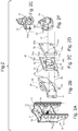
- the in the FIGS. 3 to 6 illustrated third embodiment of the measuring device 44 has a carrier 45 in the form of a measuring cross with two spaced by 60 ° or 120 ° to each other measuring arms 45a, whose free ends have eyes 45b with through holes 45d, and provided at the free ends with axial projections 45c are whose function is related to Fig. 6 is explained.
- the carrier 45 in the form of a measuring cross is provided with a central hub 46, which is substantially cylindrical, but is provided on a unilaterally axially projecting portion 46a with flats 46b.
- This axially projecting region 46a with its flattenings 46b can be inserted into a non-round recess 48c which is congruent with the hub 46 in a base plate 48, whereby the carrier 45 in the form of a measuring cross is secured against rotation with respect to the base plate 48.
- the non-circular recess 48 c of the base plate 48 terminates axially on a wall member 48 d with a central through hole 48 e for a in Fig. 3 illustrated fastening screw 49 which is screwed into a threaded bore 46c in the central hub 46 of the carrier 45 in the form of a measuring cross.
- the base plate 48 has a cylindrical depression 48a on its rear side remote from the center of the measuring instrument, into which the head of the fastening screw 49 can be lowered.
- the show FIGS. 3 and 5 clear that the base plate 48 has four through holes 48b for performing the aforementioned expansion screws 50, which are also passed through the through holes 45d of the carrier 45 and ultimately screwed into the threaded holes 26a of the standard clutch carrier 26, which in Fig. 6 is clearly recognizable.
- strain gauges or SAW elements as force sensors are respectively arranged on the measuring arms 45a and accordingly Fig. 1 wirelessly or via cable, as well as the other sensor elements, connected to the evaluation device 40.
- the measuring device 44 is as a module package from the Anschraubplatte 28, 30 of the standard hitch 27, 29, the adapter plate 35, the base plate 48, the carrier 45 in the form of a measuring cross and the standard coupling carrier 26, which are clamped by means of the expansion screws 50 against each other, at one fixed to the motorized vehicle 1 standard towing hitch 8 height adjustable attachable.
- Fig. 8 illustrated in an axial sectional view of a fourth embodiment of the features of the invention having measuring device 60 advantageously has only a very few components, which has a favorable effect on the manufacturing costs and assembly costs.
- this measuring device 60 not only the axial components of compressive and tensile forces between a towing vehicle and a hitch or attachment can measure very well, but also their spatial components.
- the measuring device 60 has a measuring cross-shaped carrier 71, which also carries four sensor elements 79, 80, which serve as force sensors and preferably designed as load cells, strain gauges or SAW elements are.
- the four sensor elements 79, 80 are arranged at four, between 60 ° and 120 ° staggered, radially extending measuring arms 74, 75 of the carrier 71, and they are as already described with an evaluation device 40 in signal connection.
- the messnchförmige carrier 71 has radially inwardly on a central hub 77, which extends axially a little way towards a base plate 63.
- the hub 77 has a non-circular geometry, with which it is received in a complementary non-circular recess 86 of the base plate 63.
- a fixing screw 70 For frictional connection of the base plate 63 with the messnchförmigen carrier 71 is a fixing screw 70, which is screwed into a threaded bore 69 of a central wall member 68 of the base plate 63 and into a threaded bore 78 of the hub 77 of the measuring cross-shaped carrier 71.
- the screw head In order to avoid an axial protrusion of this fastening screw 70, the screw head is received in a central, axial and cylindrical recess 67 of the base plate 63.
- the base plate 63 itself is firmly connected to the sensor remote side with a coupling carrier 61.
- Fixing screws 65, 66 serve this purpose, which are screwed into threaded bores 62 in the coupling carrier 61 and into threaded bores 64 in the base plate 63.
- the messnchförmige carrier 71 is fixed base plate remote with a Anschraubplatte 81 which carries a zuglanguage solution of a standard trailer hitch 27.
- the connection of the carrier 71 with this Anschraubplatte 81 is realized by means of fastening screws 84, 85 which are screwed into threaded holes 82 in the mounting plate 81 and threaded holes 76 in the radially outwardly formed eyes 72, 73 of the messnchförmigen carrier 71.
- the measuring device 60 it is provided that at the radial outer ends of the measuring arms 74, 75 of the measuring cross-shaped carrier 71 to the screw plate 81 for the standard coupling 27 facing axial projections 83 are formed on the aforementioned eyes 72, 73, which serve as spacers for the measuring arms 74, 75 relative to the screw 81.
- this measuring device 60 as a module package can be attached in a height-adjustable manner to a standard towing hanger 8 fastened to the motorized vehicle 1.
- This module package consists of the necessary sensors 79, 80 and mounting screws 65, 66, 70, 84, 85 only of the four components screw plate 81 with standard hitch 27, messnchförmiger carrier 71, base plate 48 and coupling carrier 61st
Landscapes
- Engineering & Computer Science (AREA)
- Mechanical Engineering (AREA)
- Transportation (AREA)
- Life Sciences & Earth Sciences (AREA)
- Physics & Mathematics (AREA)
- Chemical & Material Sciences (AREA)
- Soil Sciences (AREA)
- Environmental Sciences (AREA)
- General Physics & Mathematics (AREA)
- Analytical Chemistry (AREA)
- Combustion & Propulsion (AREA)
- Zoology (AREA)
- Fluid Mechanics (AREA)
- Force Measurement Appropriate To Specific Purposes (AREA)
Applications Claiming Priority (1)
| Application Number | Priority Date | Filing Date | Title |
|---|---|---|---|
| DE102018106855.7A DE102018106855A1 (de) | 2018-03-22 | 2018-03-22 | Messeinrichtung zum Messen von Kräften und/oder Momenten zwischen einem motorisierten Fahrzeug und einem davon gezogenen oder geschobenen Anhänger oder Anbaugerät |
Publications (2)
| Publication Number | Publication Date |
|---|---|
| EP3553486A2 true EP3553486A2 (fr) | 2019-10-16 |
| EP3553486A3 EP3553486A3 (fr) | 2020-02-26 |
Family
ID=65818410
Family Applications (1)
| Application Number | Title | Priority Date | Filing Date |
|---|---|---|---|
| EP19163596.0A Withdrawn EP3553486A3 (fr) | 2018-03-22 | 2019-03-19 | Dispositif de mesure permettant de mesurer la force et / ou les moments entre un véhicule motorisé et une remorque tirée ou poussée |
Country Status (3)
| Country | Link |
|---|---|
| US (1) | US10866153B2 (fr) |
| EP (1) | EP3553486A3 (fr) |
| DE (1) | DE102018106855A1 (fr) |
Cited By (5)
| Publication number | Priority date | Publication date | Assignee | Title |
|---|---|---|---|---|
| NL2026114B1 (en) * | 2020-07-22 | 2022-03-21 | Daf Trucks Nv | A vehicle. |
| WO2022111790A1 (fr) * | 2020-11-24 | 2022-06-02 | Zf Cv Systems Global Gmbh | Dispositif de mesure de forces et/ou de moments entre un véhicule tracteur et un véhicule remorque d'un ensemble de véhicules |
| WO2022263338A1 (fr) * | 2021-06-15 | 2022-12-22 | Zf Cv Systems Global Gmbh | Procédé et dispositif de commande de freinage d'un train de véhicules |
| DE102021117704A1 (de) | 2021-07-08 | 2023-01-12 | Deere & Company | In einer Abschleppbetriebsart betreibbare selbstfahrende landwirtschaftliche Arbeitsmaschine |
| WO2023110343A1 (fr) * | 2021-12-17 | 2023-06-22 | Zf Cv Systems Global Gmbh | Procédé de commande de traction d'un véhicule ou d'un ensemble attelé |
Families Citing this family (6)
| Publication number | Priority date | Publication date | Assignee | Title |
|---|---|---|---|---|
| DE102019123237A1 (de) * | 2019-02-19 | 2020-08-20 | Westfalia-Automotive Gmbh | Tragbauteil als Bestandteil eines Anhängers oder Lastenträgers |
| DE202020005868U1 (de) | 2020-11-24 | 2022-12-06 | Zf Cv Systems Global Gmbh | Messeinrichtung zum Messen von Kräften und/oder Momenten zwischen einem Zugfahrzeug und einem Anhängefahrzeug einer Fahrzeugkombination |
| DE102021133760A1 (de) | 2021-12-17 | 2023-06-22 | Zf Cv Systems Global Gmbh | Verfahren und Vorrichtung zur Antriebssteuerung eines Fahrzeugzugs |
| EP4227657A1 (fr) | 2022-02-10 | 2023-08-16 | ZF CV Systems Global GmbH | Dispositif de mesure pour mesurer des forces et/ou des moments entre un véhicule de remorquage et un véhicule à remorque d'une combinaison de véhicule avec compensation de température |
| US11608127B1 (en) * | 2022-04-28 | 2023-03-21 | Mod.Al Group, Inc. | Trailer electrical connector assembly |
| DE102022213832A1 (de) | 2022-12-19 | 2024-06-20 | Zf Cv Systems Global Gmbh | Messeinrichtung zum Messen von an einer Fahrzeugkombination wirkenden Kräften und Verfahren zum Betreiben derselben |
Citations (2)
| Publication number | Priority date | Publication date | Assignee | Title |
|---|---|---|---|---|
| EP0686839A2 (fr) * | 1994-06-07 | 1995-12-13 | Hottinger Baldwin Messtechnik Gmbh | Attelage de remorque avec capteur de force |
| EP2893793A1 (fr) | 2013-12-19 | 2015-07-15 | Deere & Company | Système de détection de force de traction pour un tracteur agricole |
Family Cites Families (21)
| Publication number | Priority date | Publication date | Assignee | Title |
|---|---|---|---|---|
| DE2752641A1 (de) * | 1977-11-25 | 1979-05-31 | Bosch Gmbh Robert | Deichselkraftregeleinrichtung |
| SE8400484D0 (sv) * | 1984-01-31 | 1984-01-31 | Slim Borgudd | Anordning for metning av dynamisk och statisk lastpakenning vid en draganordning for t ex drivorgan |
| US4573362A (en) * | 1984-07-09 | 1986-03-04 | Eaton Corporation | Multi-axis load transducer |
| US5149121A (en) * | 1987-08-05 | 1992-09-22 | Pfister Gbmh | Force measuring device |
| US4864874A (en) * | 1987-08-05 | 1989-09-12 | Pfister Gmbh | Force measuring device |
| DE3907763A1 (de) * | 1989-03-10 | 1990-09-27 | Bosch Gmbh Robert | Vorrichtung zum bestimmen der deichselkraefte eines anhaengers |
| SE464374B (sv) * | 1989-08-04 | 1991-04-15 | Siarr Sweden Ab | Kraftmaetaranordning foer maetning av vertikalkraftkomponenten verkande paa ett kopplingsdon mellan ett dragfordon och ett slaepfordon |
| DE3935479A1 (de) * | 1989-10-25 | 1991-05-02 | Pfister Gmbh | Anhaengerkupplung |
| US5213396A (en) * | 1990-12-06 | 1993-05-25 | Avery Larry L | Towed vehicle brake activation method and apparatus |
| EP0575634B1 (fr) * | 1992-05-25 | 1996-10-09 | Hottinger Baldwin Messtechnik Gmbh | Palpeur de couple |
| GB9302762D0 (en) * | 1993-02-11 | 1993-03-24 | Lucas Ind Plc | Improvements in draw-bar couplings for articulated vehicles |
| GB9907523D0 (en) * | 1999-04-01 | 1999-05-26 | Evans Kenneth S | Tow coupling sensor |
| GB2353340B (en) * | 1999-08-20 | 2003-11-05 | Vincent Roy Garvey | Trailer safety |
| KR100910972B1 (ko) * | 2002-12-07 | 2009-08-05 | 엘지전자 주식회사 | 대화형 광디스크 장치에서의 재생 제어방법 |
| DE102007036429A1 (de) * | 2007-08-02 | 2009-02-05 | Deere & Company, Moline | Steuerungssystem und Verfahren zum Betreiben eines Steuerungssystems zum Lenken eines an ein landwirtschafliches Nutzfahrzeug anagekoppelten Anbaugeräts |
| DE102009022343B4 (de) * | 2009-05-15 | 2016-04-28 | Brosa Ag | Kraftmesssystem zum Messen von Schub- bzw. Druckkräften, insbesondere bei Spreadern |
| DE102010004336A1 (de) * | 2009-07-30 | 2011-03-03 | Diemer, Andreas | Stützlastmessungsvorrichtung und Nachrüstverfahren für eine Fahrzeug-Anhängevorrichtung |
| US20130253814A1 (en) * | 2012-03-24 | 2013-09-26 | Alvin R. Wirthlin | System and Method for Gauging Safe Towing Parameters |
| US9550399B2 (en) * | 2012-12-21 | 2017-01-24 | Intelli-Hitch, Llc | Tow hitch with brake sensor system and method of use |
| DE202013008872U1 (de) * | 2013-10-05 | 2015-01-07 | Josef Scharmüller | Anhängebock für ein Zugfahrzeug |
| CA2941614A1 (fr) * | 2014-03-05 | 2015-09-11 | Kevin Mcallister | Support a rotule pour mesurer le poids du timon d'une remorque |
-
2018
- 2018-03-22 DE DE102018106855.7A patent/DE102018106855A1/de active Pending
-
2019
- 2019-03-19 EP EP19163596.0A patent/EP3553486A3/fr not_active Withdrawn
- 2019-03-22 US US16/361,302 patent/US10866153B2/en active Active
Patent Citations (2)
| Publication number | Priority date | Publication date | Assignee | Title |
|---|---|---|---|---|
| EP0686839A2 (fr) * | 1994-06-07 | 1995-12-13 | Hottinger Baldwin Messtechnik Gmbh | Attelage de remorque avec capteur de force |
| EP2893793A1 (fr) | 2013-12-19 | 2015-07-15 | Deere & Company | Système de détection de force de traction pour un tracteur agricole |
Cited By (6)
| Publication number | Priority date | Publication date | Assignee | Title |
|---|---|---|---|---|
| NL2026114B1 (en) * | 2020-07-22 | 2022-03-21 | Daf Trucks Nv | A vehicle. |
| WO2022111790A1 (fr) * | 2020-11-24 | 2022-06-02 | Zf Cv Systems Global Gmbh | Dispositif de mesure de forces et/ou de moments entre un véhicule tracteur et un véhicule remorque d'un ensemble de véhicules |
| WO2022263338A1 (fr) * | 2021-06-15 | 2022-12-22 | Zf Cv Systems Global Gmbh | Procédé et dispositif de commande de freinage d'un train de véhicules |
| DE102021117704A1 (de) | 2021-07-08 | 2023-01-12 | Deere & Company | In einer Abschleppbetriebsart betreibbare selbstfahrende landwirtschaftliche Arbeitsmaschine |
| US12396381B2 (en) | 2021-07-08 | 2025-08-26 | Deere & Company | Self-propelled agricultural work machine having a towing mode |
| WO2023110343A1 (fr) * | 2021-12-17 | 2023-06-22 | Zf Cv Systems Global Gmbh | Procédé de commande de traction d'un véhicule ou d'un ensemble attelé |
Also Published As
| Publication number | Publication date |
|---|---|
| US20190293505A1 (en) | 2019-09-26 |
| EP3553486A3 (fr) | 2020-02-26 |
| US10866153B2 (en) | 2020-12-15 |
| DE102018106855A1 (de) | 2019-09-26 |
Similar Documents
| Publication | Publication Date | Title |
|---|---|---|
| EP3553486A2 (fr) | Dispositif de mesure permettant de mesurer la force et / ou les moments entre un véhicule motorisé et une remorque tirée ou poussée | |
| EP3553483B1 (fr) | Dispositif de mesure permettant de mesurer la force et / ou les moments entre un véhicule motorisé et une remorque tirée ou poussée | |
| EP2452839B1 (fr) | Dispositif de support | |
| DE112018001492B4 (de) | Auf Magnetoelastizität beruhende Sensoranordnung | |
| DE60036184T2 (de) | Anhängerkupplung mit Kraftsensor | |
| EP2567837B1 (fr) | Unité de support | |
| EP3455091B1 (fr) | Dispositif permettant de tracter une remorque et/ou de maintenir un ensemble porte-charge | |
| DE112011101867B4 (de) | Fahrzeugfunktionsprüfstand | |
| EP3227130A1 (fr) | Attelage de remorque muni d'un capteur | |
| DE102016109425A1 (de) | Messmodul mit Kraft- und Beschleunigungssensoren zur Gewichtsermittlung eines an ein Zugfahrzeug gekoppelten Anhängefahrzeuges | |
| DE102016215083A1 (de) | Vorrichtung und Verfahren zum Überwachen zumindest einer Fahrwerkskomponente | |
| EP0548487B1 (fr) | Dispositif pour mesurer une déformation d'une pièce de construction | |
| EP3433113B1 (fr) | Elément support doté d'un capteur | |
| EP1760446A2 (fr) | Banc d'essai du fonctionnement de véhicule | |
| DE102006057327B4 (de) | Messvorrichtung für Sattelaufliegerkräfte | |
| DE102014018472B4 (de) | Wägevorrichtung und Wägesystem für Fahrzeuganhänger | |
| DE102021133762A1 (de) | Kopplungsvorrichtung zum Koppeln eines Zugfahrzeugs mit einem Anhängefahrzeug | |
| WO1994016933A1 (fr) | Dispositif de mesure et d'affichage de la charge d'une semi-remorque | |
| EP3517327A1 (fr) | Dispositif de traction | |
| DE202020005868U1 (de) | Messeinrichtung zum Messen von Kräften und/oder Momenten zwischen einem Zugfahrzeug und einem Anhängefahrzeug einer Fahrzeugkombination | |
| EP3608205A1 (fr) | Procédé de détermination de l'angle de flèche d'un attelage de véhicule | |
| WO2022111790A1 (fr) | Dispositif de mesure de forces et/ou de moments entre un véhicule tracteur et un véhicule remorque d'un ensemble de véhicules | |
| DE102004053743A1 (de) | Lenkbare Achse mit Drehwinkelsensorelement für ein Kraftfahrzeug | |
| DE102007034160A1 (de) | Kraftmessbolzen | |
| EP4514676A1 (fr) | Système d'accouplement pour un véhicule tracteur |
Legal Events
| Date | Code | Title | Description |
|---|---|---|---|
| PUAI | Public reference made under article 153(3) epc to a published international application that has entered the european phase |
Free format text: ORIGINAL CODE: 0009012 |
|
| STAA | Information on the status of an ep patent application or granted ep patent |
Free format text: STATUS: THE APPLICATION HAS BEEN PUBLISHED |
|
| AK | Designated contracting states |
Kind code of ref document: A2 Designated state(s): AL AT BE BG CH CY CZ DE DK EE ES FI FR GB GR HR HU IE IS IT LI LT LU LV MC MK MT NL NO PL PT RO RS SE SI SK SM TR |
|
| AX | Request for extension of the european patent |
Extension state: BA ME |
|
| PUAL | Search report despatched |
Free format text: ORIGINAL CODE: 0009013 |
|
| AK | Designated contracting states |
Kind code of ref document: A3 Designated state(s): AL AT BE BG CH CY CZ DE DK EE ES FI FR GB GR HR HU IE IS IT LI LT LU LV MC MK MT NL NO PL PT RO RS SE SI SK SM TR |
|
| AX | Request for extension of the european patent |
Extension state: BA ME |
|
| RIC1 | Information provided on ipc code assigned before grant |
Ipc: G01L 5/16 20200101ALI20200120BHEP Ipc: B60T 1/00 20060101ALI20200120BHEP Ipc: A01B 63/00 20060101ALI20200120BHEP Ipc: B60D 1/00 20060101ALI20200120BHEP Ipc: G01L 5/13 20060101AFI20200120BHEP |
|
| STAA | Information on the status of an ep patent application or granted ep patent |
Free format text: STATUS: REQUEST FOR EXAMINATION WAS MADE |
|
| 17P | Request for examination filed |
Effective date: 20200826 |
|
| RBV | Designated contracting states (corrected) |
Designated state(s): AL AT BE BG CH CY CZ DE DK EE ES FI FR GB GR HR HU IE IS IT LI LT LU LV MC MK MT NL NO PL PT RO RS SE SI SK SM TR |
|
| RAP3 | Party data changed (applicant data changed or rights of an application transferred) |
Owner name: ZF CV SYSTEMS HANNOVER GMBH |
|
| GRAP | Despatch of communication of intention to grant a patent |
Free format text: ORIGINAL CODE: EPIDOSNIGR1 |
|
| STAA | Information on the status of an ep patent application or granted ep patent |
Free format text: STATUS: GRANT OF PATENT IS INTENDED |
|
| INTG | Intention to grant announced |
Effective date: 20211102 |
|
| RAP1 | Party data changed (applicant data changed or rights of an application transferred) |
Owner name: ZF CV SYSTEMS EUROPE BV |
|
| GRAS | Grant fee paid |
Free format text: ORIGINAL CODE: EPIDOSNIGR3 |
|
| STAA | Information on the status of an ep patent application or granted ep patent |
Free format text: STATUS: THE APPLICATION IS DEEMED TO BE WITHDRAWN |
|
| 18D | Application deemed to be withdrawn |
Effective date: 20220315 |