EP3123867B1 - Method and device for simplified alignment of a filling machine for sausage production - Google Patents
Method and device for simplified alignment of a filling machine for sausage production Download PDFInfo
- Publication number
- EP3123867B1 EP3123867B1 EP15179017.7A EP15179017A EP3123867B1 EP 3123867 B1 EP3123867 B1 EP 3123867B1 EP 15179017 A EP15179017 A EP 15179017A EP 3123867 B1 EP3123867 B1 EP 3123867B1
- Authority
- EP
- European Patent Office
- Prior art keywords
- height
- filling machine
- inclination
- machine
- actual
- Prior art date
- Legal status (The legal status is an assumption and is not a legal conclusion. Google has not performed a legal analysis and makes no representation as to the accuracy of the status listed.)
- Active
Links
- 238000000034 method Methods 0.000 title claims description 29
- 238000004519 manufacturing process Methods 0.000 title claims description 8
- 235000013580 sausages Nutrition 0.000 title claims description 5
- 230000009471 action Effects 0.000 claims description 8
- 230000003287 optical effect Effects 0.000 claims description 7
- 230000000007 visual effect Effects 0.000 claims description 2
- 238000005259 measurement Methods 0.000 description 10
- 230000008569 process Effects 0.000 description 9
- 238000009530 blood pressure measurement Methods 0.000 description 2
- 230000000694 effects Effects 0.000 description 2
- XLYOFNOQVPJJNP-UHFFFAOYSA-N water Substances O XLYOFNOQVPJJNP-UHFFFAOYSA-N 0.000 description 2
- 208000019300 CLIPPERS Diseases 0.000 description 1
- 230000001133 acceleration Effects 0.000 description 1
- 230000008901 benefit Effects 0.000 description 1
- 230000008859 change Effects 0.000 description 1
- 238000006243 chemical reaction Methods 0.000 description 1
- 208000021930 chronic lymphocytic inflammation with pontine perivascular enhancement responsive to steroids Diseases 0.000 description 1
- 238000004140 cleaning Methods 0.000 description 1
- 238000012937 correction Methods 0.000 description 1
- 239000003599 detergent Substances 0.000 description 1
- 238000010586 diagram Methods 0.000 description 1
- 235000013305 food Nutrition 0.000 description 1
- 230000005484 gravity Effects 0.000 description 1
- 230000001939 inductive effect Effects 0.000 description 1
- 238000009776 industrial production Methods 0.000 description 1
- QSHDDOUJBYECFT-UHFFFAOYSA-N mercury Chemical compound [Hg] QSHDDOUJBYECFT-UHFFFAOYSA-N 0.000 description 1
- 229910052753 mercury Inorganic materials 0.000 description 1
- 235000011837 pasties Nutrition 0.000 description 1
- 229910000679 solder Inorganic materials 0.000 description 1
- 239000000725 suspension Substances 0.000 description 1
- 238000002604 ultrasonography Methods 0.000 description 1
Images

Classifications
-
- A—HUMAN NECESSITIES
- A22—BUTCHERING; MEAT TREATMENT; PROCESSING POULTRY OR FISH
- A22C—PROCESSING MEAT, POULTRY, OR FISH
- A22C11/00—Sausage making ; Apparatus for handling or conveying sausage products during manufacture
- A22C11/02—Sausage filling or stuffing machines
- A22C11/0245—Controlling devices
-
- A—HUMAN NECESSITIES
- A22—BUTCHERING; MEAT TREATMENT; PROCESSING POULTRY OR FISH
- A22C—PROCESSING MEAT, POULTRY, OR FISH
- A22C11/00—Sausage making ; Apparatus for handling or conveying sausage products during manufacture
- A22C11/02—Sausage filling or stuffing machines
-
- A—HUMAN NECESSITIES
- A22—BUTCHERING; MEAT TREATMENT; PROCESSING POULTRY OR FISH
- A22C—PROCESSING MEAT, POULTRY, OR FISH
- A22C18/00—Plants, factories, or the like for processing meat
Definitions
- the invention relates to a method for aligning a filling machine, in particular for sausage production.
- the present invention has the object to provide a method for aligning a filling machine, as well as a corresponding filling machine, which make it possible that the filling machine can be aligned in a simple and reliable manner in their height and / or inclination.
- step c on the basis of a deviation between actual and desired state, it can be calculated how the filling machine has to be aligned via corresponding setting elements in order to reach the desired state of height and / or inclination, in particular in which direction and around which amount ( ⁇ a) the filling machine has to be adjusted in height at different places by respective machine feet.
- the locations are preferably in the corner regions of the filling machine.
- the positions can correspond to the positions of the machine feet.
- step d it is also possible for the height and / or inclination to be automatic in step d, i. that drives (hydraulic, pneumatic) or servomotors of the adjustment elements for height adjustment of the machine feet are automatically controlled.
- the filling machine is then able to independently indicate their deviating position to the desired state and automatically perform corrections.
- Advantageous then is the implementation of a scheme.
- the checking of the actual state and the adjustment to the desired state can occur once at the beginning of the adjustment process, continuously or cyclically during the adjustment process.
- a visual or audible indication is given, so that the operator knows that the filling machine is now in the desired state.
- an optical and / or acoustic display already takes place for adjusting the individual adjusting elements when the adjusting element has been correctly adjusted such that the filling machine has been moved by the correct amount in the correct direction through the respective adjusting element.
- Such feedback greatly facilitates the adjustment process because, when the operator is at the bottom of the machine to adjust the machine feet, he immediately recognizes when the machine base is in the correct position.
- an acoustic feedback is also be made on a corresponding display, ie for example display.
- the height can be adjusted very precisely because, for example, fractions of a thread rotation can be performed accurately.
- the actual state of the height and / or the inclination may be effected via measured values from at least one measuring device integrated in the filling machine and / or via measured values of an external measuring device.
- An integrated measuring device has the advantage that no additional instruments or tools are needed and therefore no suitable tool must be at hand and no knowledge in dealing with a corresponding measuring device is required. This is particularly advantageous in terms of the risk of damage and hygiene.
- an external measuring device it is also possible for an external measuring device to be provided which feeds measured values, for example via cable or radio link, Bluetooth etc., to the calculation unit.
- the calculation device can be designed so that it can calculate on the basis of a deviation between the actual state and the desired state, how the filling machine has to be aligned via corresponding adjustment elements in order to achieve the desired state of the height and / or inclination, in particular in which direction and by what amount ( ⁇ a) the filling machine has to be adjusted in height by respective machine feet at certain corner areas.
- the filling machine preferably has a display which indicates a deviation from the actual and desired state and / or indicates a recommended course of action for adjusting corresponding setting elements, in particular for adjusting the height of the machine feet of the filling machine.
- the filling machine has at least one adjusting element, preferably four height-adjustable feet, wherein the at least one adjusting element in each case comprises a drive which is - in particular automatically - driven by the calculating device until a corresponding desired value is reached. This can be done automatically via the calculation unit or e.g. from an operator, preferably according to a handling instruction.
- the filling machine advantageously has an optical and / or acoustic display which indicates when the desired state of height and / or inclination is reached and / or indicates when a setting element has been correctly adjusted.
- the surface may be flat, ie, for example at a right angle to the side wall or preferably sloping outwards or curved, such that water is discharged can be.
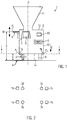
- the machine is placed on machine feet 3, here four machine feet 3a, b, c, d at each corner of the housing.
- the machine feet 3 have adjusting elements 9, via which the height of the filling machine 1, ie the Height of a reference point, here the distance between reference point P1, P2, P3 can be adjusted to the machine base or ground 4.
- Fig. 1 As can be seen, the ground or machine base 4, as shown by the dashed lines, be inclined. Since the filling tube 6 or its central axis M must be arranged correctly at a certain height or to a subsequent attachment machine, the height b between the center axis of the filling tube 6 and the bottom 4 must be set exactly and adjusted on uneven ground. Also, a plant reference plane A, for example, a plane that is perpendicular to the longitudinal axis of the machine, for example, a plane that includes the surface 13 of the housing or a plane that is spanned by at least three corners at the bottom of the machine housing, for example, horizontal, ie be aligned perpendicular to the gravitation G.
- a plant reference plane A for example, a plane that is perpendicular to the longitudinal axis of the machine, for example, a plane that includes the surface 13 of the housing or a plane that is spanned by at least three corners at the bottom of the machine housing, for example, horizontal, ie be
- the middle axis M of the filling tube 6 should advantageously lie in a corresponding plane which is perpendicular to the gravitational vector and should also be oriented perpendicular to the gravitational vector G or perpendicular to the longitudinal axis L of the filling machine.
- the filling machine should be placed inclined to a horizontal plane, as will be explained in more detail below.
- the filling machine has a calculation unit 10 in which measured values relating to the actual state of the height and / or the inclination and values relating to the desired state of the height and / or inclination can be stored.
- At least one measuring device 7 for measuring the height of the filling machine, at least one measuring device 7, in particular in the form of a distance sensor, can be provided, which can measure the distance from a reference point P1, P2, P3 to the machine base 4.
- Fig. 1 only the distance sensors 7a, 7b are shown by way of example, whereby corresponding distance sensors may also be located in the corner regions at the feet 3d and 3c in this embodiment.
- Corresponding distance measurement values a here for example measure the distance between the machine floor 14 and the machine base 4 are forwarded to the computing device 10.
- a distance meter 7 can also be provided in the region of the filling tube 6, via which the distance b between the central axis m of the filling tube and the machine base 4 is measured and forwarded to the calculating device 10.
- the calculation device 10 can determine, based on a desired-actual state comparison, whether the filling tube 6 is in a correct position.
- the reference point P of the measurement is irrelevant since, due to the known dimensions of the filling machine, it can also be measured starting from other measuring points, e.g. P1, P2, the position of the center axis of the filling tube can be determined or calculated.
- the distance sensors used are, for example, optical sensors or a device for distance measurement on the basis of travel time measurement and / or reflection (for example infrared, laser, sound, ultrasound), but also a force-sensitive and / or spring-actuated sensor / button can be used. Furthermore, the corresponding height can be measured not only via an electronic measuring device but also manually by means of a meter bar, yardstick, etc., and input via a schematically represented input unit 8 and transmitted to the calculation unit 10.
- the filling machine 1 preferably comprises an integrated tilt sensor 5, which transmits corresponding measured values to the calculation device 10.
- the inclination sensor is not integrated in the filling machine, but an external inclination measuring device (not shown) is provided, which is for example applied to the surface 13 or to a side wall of the filling machine 1, and the detected measured values with respect to the inclination to the computing device 10 either via cable or radio link Bluetooth, etc. forwards.
- the measured values generated by the external inclination measuring device to be input by the operator via an input unit 8 and thus stored in the calculating device 10.
- Suitable here are, for example, microelectromechanical spring-mass systems, devices for pressure measurement at several contact points, here pressure measurement on the foot surfaces facing the machine base 4, optical measuring devices, in particular camera, laser tracking, optical solder, laser plummet, gyroscope / gyro instrument, strain gauges / Force transducers attached to the filling machine and the actual position and Detect the position of the filling machine.
- devices for inductive or capacitive measurement can be provided, which are attached to the filling machine and detect the position and position of the filling machine by distance measurement.
- the inclination can also be determined via at least three distance sensors, which are preferably in a plane perpendicular to the longitudinal axis L, and measure the distance to the bottom 4, for example, the distance sensors 7 a, b, (c, d not shown) in the four corners the filling machine.
- concrete recommendations for action can be given and displayed to adjust the setting elements (for example thread turns) and thus to change the orientation of the filling machine and to bring into the desired condition.
- a further expansion stage may be to realize the adjustment of the machine orientation automatically via previously described drives, then the implementation of a control is advantageous.
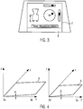
- Fig. 3 shows, for example, the measured height b of the filling machine, as well as a representation of the measured slope over two mutually perpendicular bars - according to the display of an electronic spirit level.
- b target 105 cm
- b actual 103 cm
- ⁇ 1 °
- ⁇ 0.5 °
- a foot 3a 20 cm
- a foot 3b 18 cm
- a foot 3c 21 cm
- a foot 3d 20.5 cm.
- the adjustment is not manual, but via a drive, as described above.
- either the operator can actuate the drive, which also here as described above, comes to a feedback when the actual position of the machine base 3 is reached, or it can be done an automatic control of the drive, so that the adjustment of the machine feet 3 takes place automatically via a control device. If the filling machine 1 as a whole is correctly aligned, ie tuning the inclination and height, this can also be displayed visually or acoustically accordingly.
- the distance sensors for checking the adjustment of the individual machine feet and be determined for example by signals of the drive by what amount .DELTA.l the respective foot has been adjusted.
- the orientation of the filling machine can be done, for example, the first time a filling machine 1 in a production environment, after the implementation of a filling machine within a production environment, as well as the adjustment of the machine height due to divergent requirements, for example, for connecting various attachment machines or ergonomic considerations.
- the computing device calculates on the basis of the deviation between actual and desired state, by what amount and in which direction the filling machine has to be adjusted by respectively ⁇ a via the adjustable machine feet, and according to a preferred embodiment, like corresponding adjusting elements 9 must be adjusted to achieve the desired state of height and / or inclination, in which case it is determined in particular by what amount and in which direction the machine feet of the filling machine must be adjusted in height.
- a recommendation for action can be displayed on the display 2, which indicates at least in which direction and preferably by what amount the machine feet each have to be adjusted in height.
- the calculation device can also forward signals to controls that drive the drives of the setting devices of the machine feet according to the calculation.
- the alignment procedure starts again to check if the adjustment was successful. If it then appears that the actual state corresponds to the desired state, the method is ended. Otherwise, the process loop will be run through again.
Description
Die Erfindung betrifft ein Verfahren zum Ausrichten einer Füllmaschine, insbesondere zur Wurstherstellung.The invention relates to a method for aligning a filling machine, in particular for sausage production.
Eine solche Füllmaschine ist bereits aus der
Bei der Inbetriebnahme von Füllmaschinen in einer Produktionsumgebung wird zumeist darauf geachtet, dass diese in der Höhe nivelliert ist. Zudem wird versucht, die Füllmaschine möglichst waagrecht auszurichten. In seltenen Fällen kann es vorteilhaft sein, eine bestimmte, bewusste Neigung in eine oder mehrere Richtungen herzustellen (beispielsweise zur Ausrichtung der Füllmaschine an eine ebenfalls geneigt aufgestellte Anbaumaschine).When commissioning filling machines in a production environment, it is usually ensured that they are leveled in height. In addition, an attempt is made to align the filling machine as horizontally as possible. In rare cases, it may be advantageous to produce a certain, deliberate inclination in one or more directions (for example, for aligning the filling machine to a likewise tilted mounting machine).
Es kommt häufig vor, dass Fußböden in handwerklichen und industriellen Produktionsräumen eine bestimmte Neigung in verschiedene Richtungen aufweisen, beispielsweise 2 %, damit bei der Maschinen- oder Gebäudereinigung anfallendes Reinigungsmittel, sowie Schmutzwasser, gezielt durch Abläufe entsorgt werden kann. Herkömmlicherweise wird die Höhe intuitiv eingestellt oder durch beispielsweise ein Maßband unterstützt. Dann werden beispielsweise die Füße der Füllmaschinen über Gewinde in ihrer Höhe verstellt, so dass das Füllrohr der Maschine über dem Fußboden in einer bestimmten Höhe liegt (beispielsweise um passende Anbaumaschinen des nachfolgenden Prozesses anzuschließen oder aus ergonomischen Gründen). Zum Ausrichten der Neigung der Füllmaschine wird entweder kein Messwerkzeug verwendet (sondern Schätzwerte bzw. Augenmaß) oder es wird z.B. eine Wasserwaage eingesetzt.It often happens that floors in craft and industrial production areas have a certain inclination in different directions, for example, 2%, so that in the machine or building cleaning accumulating detergent, and dirty water, can be disposed of by processes. Traditionally, the height is intuitively adjusted or supported by, for example, a tape measure. Then, for example, the feet of the filling machines are adjusted in height by means of threads, so that the filling tube of the machine lies above the floor at a certain height (for example, in order to connect suitable attachment machines of the subsequent process or for ergonomic reasons). For aligning the inclination of the filling machine, either no measuring tool is used (but estimated values) or, e.g. used a spirit level.
Die Einstellung von mehreren Maschinenfüßen ist mitunter kraft- und zeitintensiv, da sich beim Verstellen eines einzelnen Maschinenfußes der Effekt auf das gesamte Einstellergebnis nur schwer abschätzten lässt und es vorkommt, dass die Füllmaschine über zwei Maschinenfüße abkippt oder ein Maschinenfuß ohne Bodenkontakt ist. Bei größeren Neigungen des Maschinenuntergrunds bzw. Fußbodens müssen Maschinenfüße im Einzelnen sehr unterschiedlich (in der Anzahl der Einstellumdrehungen) verstellt werden, um das gewünschte Ergebnis zu erhalten.The adjustment of several machine feet is sometimes power and time-consuming, because when adjusting a single machine foot, the effect on the entire setting result is difficult to estimate and it happens that the filling machine tilts over two machine feet or a machine base without ground contact. For larger inclinations of the machine base or floor, machine feet have to be adjusted very differently (in the number of setting rotations) in order to obtain the desired result.
Daher sind, selbst bei erfahrenem Personal, bei unebenen Fußböden, oft mehrere Iterationsschritte notwendig, um die Füllmaschine in eine exakte Höhen- und Ausrichtungslage einzustel len. Das Ergebnis muss, so zeigt die Erfahrung, während des Einstellvorgangs mehrfach überprüft und korrigiert werden.Therefore, even with experienced personnel, on uneven floors, often several iterations are necessary to lock the filling machine in an exact height and orientation position len. Experience shows that the result must be checked and corrected several times during the setting procedure.
Es folgt daraus, dass Füllmaschinen in der Praxis nicht immer optimal ausgerichtet sind. Ein weiterer Nachteil kommt zum Tragen, wenn an die Füllmaschine angekoppelte Anbaumaschi nen, durch eine falsch eingestellte Höhe der Füllmaschine, in Teilen oder ganz mit deren Gewicht entweder am Auslauf der Füllmaschine hängen oder versuchen, diesen nach oben zu drücken - es wirkt eine starke mechanische Belastung auf die betroffenen Bauteile, die gegebenenfalls zu plastischen Verformungen, Rissen oder Brüchen führen kann, wodurch hohe Folgekosten entstehen.
Hiervon ausgehend liegt der vorliegenden Erfindung die Aufgabe zugrunde, ein Verfahren zum Ausrichten einer Füllmaschine, sowie eine entsprechende Füllmaschine bereitzustellen, die es ermöglichen, dass die Füllmaschine auf einfache und zuverlässige Weise in ihrer Höhe und/oder Neigung ausgerichtet werden kann.
Erfindungsgemäß wird diese Aufgabe durch ein Verfahren und eine Vorrichtung gemäß den Ansprüchen 1 und 10 gelöst.
Gemäß der Erfindung wird nun die Höhe und/oder Neigung einer Füllmaschine entsprechend einem Ist-Zustand gemessen. Bevorzugt wird die Höhe und die Neigung bestimmt, denn dann kann die Füllmaschine exakt mit einer vorbestimmten Neigung bei einer vorbestimmten Höhe aufgestellt werden.
Unter Höhe der Füllmaschine versteht man hier beispielsweise den Abstand eines Anlagenbezugspunkts zum Fußboden, auf dem die Füße der Füllmaschine aufgestellt sind. Wo dieser Bezugspunkt liegt, ist für die Messung irrelevant, da aufgrund bekannter Maschinenabmessungen stets die Lage eines bestimmten Punktes an der Maschine, beispielsweise die Füllrohrachsenhöhe bestimmt werden kann.
Unter Messen der Neigung, versteht man das Messen bestimmter Werte, die herangezogen werden können, um z.B. die Neigung einer Anlagenbezugsebene (z.B. zu einer Bezugsebene insbesondere zur Horizontalebene) festzulegen. Eine Anlagenbezugsebene ist beispielsweise eine Ebene, die senkrecht auf der Längsachse L der Maschine steht, z.B. eine Ebene, die eine ebene Oberfläche des Maschinengehäuses einschließt, oder eine dazu parallele Ebene.
Die Messwerte werden dann an eine Berechnungseinheit der Füllmaschine, die Teil einer Maschinensteuerung sein kann, übermittelt. Die Berechnungseinheit vergleicht dann den Ist-Zustand der Höhe und/oder der Neigung mit einem entsprechenden Soll-Zustand der Höhe und/oder Neigung.
Dabei können entweder beispielsweise bei der Höhe direkt die Messwerte verglichen werden, oder aber es werden berechnete Werte, die von den Messwerten abhängen, mit entsprechenden Soll-Werten verglichen. Die Berechnungseinrichtung kann beispielsweise die gemessene Höhe eines Bezugspunks umrechnen auf einen anderen Bezugspunkt. Die Berechnungseinheit kann beispielsweise auch auf der Grundlage der Messwerte für die Neigung der Füllmaschine eine Anlagenbezugsebene ermitteln und die Abweichung der Neigung der Anlagenbezugsebene zur Neigung einer die Ebene schneidenden waagrechten Ebene, die senkrecht zu Gravitationsvektor "g" steht, durch Vergleich erfassen. Es ist auch möglich erfasste Neigungswinkel über Winkelfunktionen in Abstände (z.B. Abstände zwischen Maschinenboden und Maschinenuntergrund an bestimmten Stellen z.B. Bereich der Maschinenfüße) umzurechnen und zu vergleichen.It follows that filling machines are not always optimally aligned in practice. Another disadvantage comes into play when attached to the filling machine cultivation machine NEN, by an incorrectly set height of the filling machine, in parts or wholly with their weight either hang on the outlet of the filling machine or try to push it upwards - it has a strong mechanical load on the affected components, which may lead to plastic deformation, cracks or fractures, resulting in high consequential costs.
On this basis, the present invention has the object to provide a method for aligning a filling machine, as well as a corresponding filling machine, which make it possible that the filling machine can be aligned in a simple and reliable manner in their height and / or inclination.
According to the invention, this object is achieved by a method and a device according to
According to the invention, the height and / or inclination of a filling machine is measured in accordance with an actual state. Preferably, the height and the inclination is determined, because then the filling machine can be set up exactly with a predetermined inclination at a predetermined height.
By height of the filling machine is meant, for example, the distance of a plant reference point to the floor on which the feet of the filling machine are placed. Where this reference point is, is irrelevant for the measurement, since due to known machine dimensions always the location of a specific point on the machine, such as the Füllrohrachsenhöhe can be determined.
By measuring the slope, one understands the measurement of certain values that can be used, for example, to determine the inclination of a plant reference plane (eg to a reference plane, in particular to the horizontal plane). A plant reference plane is, for example, a plane which is perpendicular to the longitudinal axis L of the machine, eg a plane which encloses a flat surface of the machine housing or a plane parallel thereto.
The measured values are then transmitted to a calculation unit of the filling machine, which may be part of a machine control. The calculation unit then compares the actual state of the height and / or the inclination with a corresponding desired state of the height and / or inclination.
Either the height can be directly compared with the measured values, or calculated values that depend on the measured values are compared with corresponding desired values. The calculation device can, for example, the measured Convert the height of a reference point to another reference point. For example, the calculation unit may also determine a plant reference plane based on the measured values for the inclination of the filling machine and detect the deviation of the inclination of the plant reference plane to the inclination of a horizontal plane intersecting the plane perpendicular to the gravitational vector "g". It is also possible to calculate and compare detected inclination angles using angular functions at distances (eg distances between machine base and machine base at certain points, eg area of machine feet).
Dann kann die Höhe und/oder die Neigung auf der Grundlage des Vergleichs in Schritt c so eingestellt werden, dass ein Soll-Zustand erreicht wird.Then, the height and / or the inclination may be adjusted based on the comparison in step c so that a target state is achieved.
Die vorliegende Erfindung ermöglicht, dass stets eine korrekte Höhe der Füllmaschine eingestellt werden kann, so dass beispielsweise eine Füllrohrachse korrekt zu einer nachfolgenden Anbaumaschine ausgerichtet ist. Durch die exakte, z. B. waagrechte Ausrichtung der Füllmaschine kann die Prozesssicherheit erhöht und die Standsicherheit gewährleistet werden, selbst wenn der Fußboden im Produktionsraum uneben ist. Prinzipien, die mit Hilfe der Schwerkraft funktionieren, können optimal wirken. Es ist jedoch auch möglich, eine vorbestimmte Neigung der Anlagenbezugsebene einzustellen, wenn eine geneigt aufgestellte Anbaumaschine dies erfordert. Dies war bislang nicht möglich.The present invention makes it possible to always set a correct height of the filling machine so that, for example, a filling tube axis is correctly aligned with a subsequent growing machine. By the exact, z. B. horizontal orientation of the filling machine, the process reliability can be increased and the stability can be ensured, even if the floor is uneven in the production room. Principles that work with the help of gravity can work optimally. However, it is also possible to set a predetermined inclination of the plant reference plane, if a tilted mounted cultivation machine requires it. This has not been possible so far.
Eine verbesserte Ausrichtung der Füllmaschine kann auf einfache und zuverlässige reproduzierbare Art und Weise gewährleistet werden.Improved alignment of the filling machine can be ensured in a simple and reliable reproducible manner.
In Schritt c kann auf der Grundlage einer Abweichung zwischen Ist- und Soll-Zustand berechnet werden, wie die Füllmaschine über entsprechende Einstellelemente ausgerichtet werden muss, um den Soll-Zustand der Höhe und/oder der Neigung zu erreichen, insbesondere in welche Richtung und um welchen Betrag (Δa) die Füllmaschine an verschiedenen Stellen durch jeweilige Maschinenfüße höhenverstellt werden muss. Die Stellen liegen bevorzugt in den Eckbereichen der Füllmaschine. Die Stellen können den Positionen der Maschinenfüße entsprechen.In step c, on the basis of a deviation between actual and desired state, it can be calculated how the filling machine has to be aligned via corresponding setting elements in order to reach the desired state of height and / or inclination, in particular in which direction and around which amount (Δa) the filling machine has to be adjusted in height at different places by respective machine feet. The locations are preferably in the corner regions of the filling machine. The positions can correspond to the positions of the machine feet.
Insbesondere kann in Schritt c also auf der Grundlage einer Abweichung zwischen Ist- und Soll-Zustand berechnet werden, wie entsprechende Einstellelemente eingestellt werden müssen, um den Soll-Zustand der Höhe und/oder Neigung zu erreichen, insbesondere in welche Richtung und vorzugsweise um welchen Betrag Maschinenfüße der Maschinen höhenverstellt werden müssen. Durch die Berechnung in der Berechnungseinheit kann also exakt berechnet werden, wie der Bediener die Einstellelemente einstellen muss. Es kann für jeden Maschinenfuß angezeigt werden, wie dieser zu verstellen ist, d.h. beispielsweise um wie viele Umdrehungen und in welche Richtung ein Gewinde der verstellbaren Maschinenfüße gedreht werden muss. Im Vergleich zur bloßen Darstellung einer Abweichung auf einem Display ermöglicht das Berechnen um wieviel und in welche Richtung die Füllmaschine durch die Einstellelemente höhenverstellt werden muss eine noch einfachere Handhabung und eine schnellere Justierung.In particular, in step c, it is therefore possible to calculate on the basis of a deviation between the actual state and the desired state how appropriate adjustment elements have to be set in order to achieve the desired state of height and / or inclination, in particular in which direction and preferably around which Amount machine feet of the machines must be adjusted in height. The calculation in the calculation unit can therefore be used to calculate exactly how the operator must set the adjustment elements. It can be for every machine foot be displayed as this is to be adjusted, ie for example by how many turns and in which direction a thread of the adjustable machine feet must be rotated. Compared to the mere representation of a deviation on a display, calculating by how much and in which direction the filling machine has to be adjusted in height by the adjusting elements makes an even easier handling and a quicker adjustment possible.
Es ist möglich, dass eine Anzeige erfolgt, die eine Abweichung vom Ist- und Soll-Zustand anzeigt, so dass der Bediener diese Abweichung schnell und einfach erkennen und eine entsprechende Justierung vornehmen kann. Vorteilhafterweise zeigt die Anzeige auch eine Handlungsempfehlung an zum Justieren entsprechender Einstellelemente, insbesondere zur Höhenverstellung der Maschinenfüße der Füllmaschine. Die Handlungsempfehlung gibt dabei zumindest an in welche Richtung die einzelnen Einstellelemente bzw. Maschinenfüße höhenverstellt werden müssen- vorteilhafterweise auch noch den Betrag.It is possible that a display takes place, which indicates a deviation from the actual and desired state, so that the operator can recognize this deviation quickly and easily and make a corresponding adjustment. Advantageously, the display also indicates a recommended action for adjusting corresponding adjustment elements, in particular for height adjustment of the machine feet of the filling machine. The recommended action indicates at least in which direction the individual adjustment elements or machine feet must be adjusted in height - advantageously also the amount.
Es ist jedoch auch möglich, dass die Höhe und/oder Neigung in Schritt d automatisch erfolgt, d.h. dass Antriebe (hydraulische, pneumatische) oder Stellmotoren der Einstellelemente zur Höhenverstellung der Maschinenfüße automatisch angesteuert werden. Die Füllmaschine ist dann in der Lage, selbstständig auf deren abweichende Lage zum Soll-Zustand hinzuweisen und automatisch Korrekturen durchzuführen. Vorteilhaft ist dann die Implementierung einer Regelung. Alternativ kann die Überprüfung des Ist-Zustands und der Abgleich zum Soll-Zustand einmalig zu Beginn des Einstellprozesses, kontinuierlich oder zyklisch während des Einstellprozesses ablaufen.However, it is also possible for the height and / or inclination to be automatic in step d, i. that drives (hydraulic, pneumatic) or servomotors of the adjustment elements for height adjustment of the machine feet are automatically controlled. The filling machine is then able to independently indicate their deviating position to the desired state and automatically perform corrections. Advantageous then is the implementation of a scheme. Alternatively, the checking of the actual state and the adjustment to the desired state can occur once at the beginning of the adjustment process, continuously or cyclically during the adjustment process.
So kann es vorteilhaft sein, dass nach Schritt d zum Überprüfen des Zustands erneut die Schritte a bis c durchgeführt werden und der Einstellvorgang erst dann beendet wird, wenn bei einem erneuten Vergleich bestimmt wird, dass der Ist-Zustand dem Soll-Zustand entspricht.Thus, it may be advantageous for steps a to c to be carried out again after step d for checking the state, and the setting process to be ended only when a renewed comparison determines that the actual state corresponds to the desired state.
Vorteilhafterweise erfolgt bei Erreichen des Soll-Zustands der Höhe und/oder der Neigung eine optische oder akustische Anzeige, so dass der Bediener weiß, dass sich jetzt die Füllmaschine im Soll-Zustand befindet. Es ist jedoch auch möglich, dass bereits zum Einstellen der einzelnen Einstellelemente eine optische und/oder akustische Anzeige erfolgt, wenn das Einstellelement korrekt justiert wurde derart, dass die Füllmachine um den korrekten Betrag in die richtige Richtung durch das jeweilige Einstellelement bewegt wurde. Eine entsprechende Rückmeldung erleichtert das Einstellverfahren erheblich, da, wenn sich der Bediener, zum Einstellen der Maschinenfüße im unteren Bereich der Maschine befindet, er sofort erkennt, wenn der Maschinenfuß in der korrekten Position ist. Ganz besonders vorteilhaft ist hier eine akustische Rückmeldung. Die Anzeige kann jedoch auch an einer entsprechenden Anzeige, d.h. z.B. Display erfolgen. Somit lässt sich die Höhe besonders exakt verstellen, da beispielsweise auch Bruchteile einer Gewindedrehung genau ausgeführt werden können. Somit kann es auch ausreichen, wenn nur die Richtung der Höhenverstellung als Handlungsanweisung gegeben wird.Advantageously, when the desired state of height and / or inclination is reached, a visual or audible indication is given, so that the operator knows that the filling machine is now in the desired state. However, it is also possible that an optical and / or acoustic display already takes place for adjusting the individual adjusting elements when the adjusting element has been correctly adjusted such that the filling machine has been moved by the correct amount in the correct direction through the respective adjusting element. Such feedback greatly facilitates the adjustment process because, when the operator is at the bottom of the machine to adjust the machine feet, he immediately recognizes when the machine base is in the correct position. Especially advantageous here is an acoustic feedback. However, the display can also be made on a corresponding display, ie for example display. Thus, the height can be adjusted very precisely because, for example, fractions of a thread rotation can be performed accurately. Thus, it may also be sufficient if only the direction of the height adjustment is given as an instruction.
Um zu bestimmen, ob das Einstellelement korrekt justiert wurde, wird eine entsprechende Messung, z.B. Höhenmessung zum Boden, vorgenommen, oder aber bei Betätigung eines Antriebs durch den Operator durch Messung der Ausdrehhöhe des Antriebs bestimmt, wann die Höhenverstellung abgeschlossen ist. Entsprechendes kann auch durch Signale eines entsprechenden Schrittmotors oder eines Servoantriebs mit Drehgeber (Resolver, Inkrementalgeber, Absolutwertgeber etc.) bewerkstelligt werden.To determine if the adjustment has been adjusted correctly, a corresponding measurement, e.g. Height measurement to the ground, made, or when operating a drive by the operator by measuring the turning height of the drive determines when the height adjustment is completed. The same can be accomplished by signals of a corresponding stepper motor or a servo drive with rotary encoder (resolver, incremental encoder, absolute encoder, etc.).
Der Ist-Zustand der Höhe und/oder der Neigung kann über Messwerte aus mindestens einer in der Füllmaschine integrierten Messeinrichtung erfolgen und/oder über Messwerte einer externen Messeinrichtung. Eine integrierte Messeinrichtung bringt den Vorteil mit sich, dass keine zusätzlichen Instrumente oder Werkzeuge benötigt werden und somit kein geeignetes Werkzeug griffbereit sein muss und auch keine Kenntnisse im Umgang mit einer entsprechenden Messeinrichtung vorausgesetzt ist. Dies ist insbesondere auch im Hinblick auf die Beschädigungsgefahr und Hygiene vorteilhaft. Es ist jedoch auch möglich, dass eine externe Messeinrichtung vorgesehen ist, die Messwerte beispielsweise über Kabel oder Funkverbindung, Bluetooth etc. der Berechnungseinheit zuführt. Darüber hinaus ist es möglich, dass ein Bediener entsprechende Werte misst und manuell in die Berechnungseinrichtung eingibt.The actual state of the height and / or the inclination may be effected via measured values from at least one measuring device integrated in the filling machine and / or via measured values of an external measuring device. An integrated measuring device has the advantage that no additional instruments or tools are needed and therefore no suitable tool must be at hand and no knowledge in dealing with a corresponding measuring device is required. This is particularly advantageous in terms of the risk of damage and hygiene. However, it is also possible for an external measuring device to be provided which feeds measured values, for example via cable or radio link, Bluetooth etc., to the calculation unit. In addition, it is possible for an operator to measure corresponding values and enter them manually into the calculation device.
Der Soll-Zustand kann mindestens einer der folgenden Zustände sein:
- die Höhe mindestens eines Anlagenbezugspunkts,
- eine waagrecht ausgerichtete Anlagenbezugsebene,
- eine zu einer waagrechten Ebene geneigten Anlagenbezugsebene,
- the height of at least one asset reference point,
- a horizontally oriented system reference level,
- a plant reference plane inclined to a horizontal plane,
Eine Füllmaschine insbesondere zum Durchführen des Verfahrens nach mindestens einem der Ansprüche 1 bis 9 weist ein Maschinengehäuse auf, einen Fülltrichter, ein Füllrohr sowie Maschinenfüße.A filling machine, in particular for carrying out the method according to at least one of claims 1 to 9, has a machine housing, a filling funnel, a filling tube and machine feet.
Gemäß der vorliegenden Erfindung umfasst die Füllmaschine eine Berechnungseinheit, in der Messwerte bezüglich des Ist-Zustands der Höhe und/oder der Neigung, sowie Werte bezüglich des Soll-Zustands der Höhe und/oder der Neigung abgelegt werden können, wobei die Berechnungseinheit eine Vergleichseinrichtung umfasst zum Vergleich des Ist-Zustands mit dem Soll-Zustand bezüglich der Höhe und/oder der Neigung und mindestens ein Einstellelement vorgesehen ist, das auf der Grundlage des Vergleichs von Ist- und Soll-Zustand verstellt werden kann.
Die Berechnungseinrichtung kann so ausgebildet sein, dass sie auf der Grundlage einer Abweichung zwischen Ist- und Soll-Zustand berechnen kann, wie die Füllmaschine über entsprechende Einstellelemente ausgerichtet werden muss, um den Soll-Zustand der Höhe und/oder der Neigung zu erreichen, insbesondere in welche Richtung und um welchen Betrag (Δa) die Füllmaschine durch jeweilige Maschinenfüße an bestimmten Eckbereichen höhenverstellt werden muss.According to the present invention, the filling machine comprises a calculation unit in which measured values relating to the actual state of height and / or inclination, as well as values relating to the desired state of height and / or inclination can be filed, wherein the calculation unit comprises a comparison device is provided for comparing the actual state with the desired state with respect to the height and / or the inclination and at least one adjusting element, which can be adjusted on the basis of the comparison of the actual and desired state.
The calculation device can be designed so that it can calculate on the basis of a deviation between the actual state and the desired state, how the filling machine has to be aligned via corresponding adjustment elements in order to achieve the desired state of the height and / or inclination, in particular in which direction and by what amount (Δa) the filling machine has to be adjusted in height by respective machine feet at certain corner areas.
Die Berechnungseinheit kann auch berechnen, wie entsprechende Einstellelemente eingestellt werden müssen, um den Soll-Zustand bezüglich der Höhe und/oder Neigung zu erreichen, insbesondere in welche Richtung und um welchen Betrag die Maschinenfüße der Füllmaschine höhenverstellt werden müssen. "In welche Richtung" bedeutet hier, ob die Maschine an dem entsprechenden Fuß angehoben oder abgesenkt werden soll.The calculation unit can also calculate how appropriate adjustment elements must be set in order to achieve the desired state with respect to the height and / or inclination, in particular in which direction and by what amount the machine feet of the filling machine have to be adjusted in height. "In which direction" means here whether the machine should be raised or lowered on the corresponding foot.
Vorzugsweise weist die Füllmaschine eine Anzeige auf, die eine Abweichung von Ist- und Soll-Zustand anzeigt und/oder eine Handlungsempfehlung zum Justieren entsprechender Einstellelemente insbesondere zur Höhenverstellung der Maschinenfüße der Füllmaschine anzeigt. Vorteilhafterweise weist die Füllmaschine mindestens ein Einstellelement, vorzugsweise vier höhenverstellbare Füße auf, wobei das mindestens eine Einstellelement jeweils einen Antrieb umfasst, der - insbesondere automatisch - von der Berechnungseinrichtung angesteuert wird, bis ein entsprechender Soll-Wert erreicht wird. Dies kann automatisch über die Berechnungseinheit erfolgen oder z.B. von einem Bediener, vorzugsweise entsprechend einer Handlungsanweisung. Die Füllmaschine weist vorteilhafterweise eine optische und/oder akustische Anzeige auf, die anzeigt, wenn der Soll-Zustand der Höhe und/oder Neigung erreicht ist und/oder anzeigt, wenn ein Einstellelement korrekt justiert wurde.The filling machine preferably has a display which indicates a deviation from the actual and desired state and / or indicates a recommended course of action for adjusting corresponding setting elements, in particular for adjusting the height of the machine feet of the filling machine. Advantageously, the filling machine has at least one adjusting element, preferably four height-adjustable feet, wherein the at least one adjusting element in each case comprises a drive which is - in particular automatically - driven by the calculating device until a corresponding desired value is reached. This can be done automatically via the calculation unit or e.g. from an operator, preferably according to a handling instruction. The filling machine advantageously has an optical and / or acoustic display which indicates when the desired state of height and / or inclination is reached and / or indicates when a setting element has been correctly adjusted.
Die Füllmaschine weist mindestens eine Messeinrichtung auf zum Erfassen des Ist-Zustands bezüglich der Höhe und/oder Neigung und/oder eine Eingabeeinrichtung zur Eingabe von Messwerten der Höhe und/oder Neigung bezüglich des Ist-Zustands.The filling machine has at least one measuring device for detecting the actual state with respect to the height and / or inclination and / or an input device for inputting measured values of the height and / or inclination with respect to the actual state.
Zur Messung des Ist-Zustands der Höhe und/oder der Neigung weist die Füllmaschine mindestens einen Sensor, vorzugsweise Abstandssensor auf. Die Sensoren sind insbesondere an verschiedenen Eckbereichen der Füllmaschine angeordnet ist. Somit kann beispielsweise über Abstandssensoren im Bereich eines entsprechenden Maschinenfußes bestimmt bzw. berechnet werden, wann ein Maschinenfuß korrekt höhenverstellt ist.To measure the actual state of the height and / or inclination, the filling machine has at least one sensor, preferably a distance sensor. The sensors are arranged in particular at different corner regions of the filling machine. Thus, for example, distance sensors can be determined or calculated in the region of a corresponding machine foot when a machine foot is correctly adjusted in height.
Besonders vorteilhaft ist gemäß der vorliegenden Erfindung, wenn sowohl die Höhe der Füllmaschine als auch die Neigung bestimmt wird. Dies bringt insbesondere bei unebenen Fußböden die Möglichkeit einer korrekten einfachen und reproduzierbaren Ausrichtung mit sich. Die Füllmaschine kann dann mit einer vorbestimmten Neigung mit einer vorbestimmten Höhe ausgerichtet werden.It is particularly advantageous according to the present invention, when both the height of the filling machine and the inclination is determined. This brings with it the possibility of a correct simple and reproducible alignment especially on uneven floors. The filling machine may then be aligned with a predetermined inclination at a predetermined height.
Die vorliegende Erfindung wird nachfolgend unter Bezugnahme folgender Figuren näher erläutert:
- Fig. 1
- zeigt grobschematisch eine Seitenansicht einer Füllmaschine gemäß der vorliegenden Erfindung,
- Fig. 2
- zeigt einen Schnitt durch die Füllmaschine entlang der Linie I-I
- Fig. 3
- zeigt grobschematisch eine Anzeige der Füllmaschine,
- Fig. 4
- zeigt grobschematisch eine weitere mögliche Anzeige
- Fig. 5
- zeigt ein Flussdiagramm für ein Verfahren gemäß der vorliegenden Erfindung.
- Fig. 1
- shows a rough schematic of a side view of a filling machine according to the present invention,
- Fig. 2
- shows a section through the filling machine along the line II
- Fig. 3
- shows a rough schematic of an indication of the filling machine,
- Fig. 4
- shows roughly a further possible indication
- Fig. 5
- shows a flowchart for a method according to the present invention.
Wie aus
Über das Höhenverstellen der Einstellelemente 9 der Maschinenfüße 3 kann die Füllmaschine 1 entsprechend ausgerichtet werden. Das Einstellelement kann dabei z.B. ein Gewinde umfassen, wobei die Höhe der Füße durch Drehen des unteren Bereichs der Füße im Gewinde um eine bestimmte Umdrehungsanzahl eingestellt werden kann. Das Einstellelement kann jedoch nicht nur manuell betätigt werden, sondern es kann alternativ auch ein Antrieb vorgesehen sein, beispielsweise ein Stellantrieb, bzw. ein hydraulischer Antrieb, über den wie auch bei einer manuellen Einstelleinrichtung die Abmessung I der Maschinenfüße 3 und somit die Höhe und Neigung der Füllmaschine 1 einstellbar ist.About the height adjustment of the adjusting
Die Füllmaschine weist erfindungsgemäß eine Berechnungseinheit 10 auf, in der Messwerte bezüglich des Ist-Zustands der Höhe und/oder der Neigung sowie Werte bezüglich des Soll-Zustands der Höhe und/oder der Neigung abgelegt werden können.According to the invention, the filling machine has a
Zum Messen der Höhe der Füllmaschine kann mindestens eine Messeinrichtung 7, insbesondere in Form eines Abstandssensors vorgesehen sein, der den Abstand von einem Bezugspunkt P1, P2, P3 zu dem Maschinenuntergrund 4 messen kann.For measuring the height of the filling machine, at least one measuring device 7, in particular in the form of a distance sensor, can be provided, which can measure the distance from a reference point P1, P2, P3 to the
In
Zusätzlich oder alternativ kann beispielsweise auch im Bereich des Füllrohrs 6 ein Abstandsmesser 7 vorgesehen sein, über den der Abstand b zwischen der Mittelachse m des Füllrohrs und dem Maschinenuntergrund 4 gemessen wird und an die Berechnungseinrichtung 10 weitergeleitet wird. Somit kann direkt oder indirekt bestimmt werden, auf welcher Höhe sich das Füllrohr 6 befindet, wobei die Berechnungseinrichtung 10 aufgrund eines Soll-Ist-Zustandsvergleichs, feststellen kann, ob sich das Füllrohr 6 in einer korrekten Position befindet. Der Bezugspunkt P der Messung ist jedoch unerheblich, da aufgrund der bekannten Abmessungen der Füllmaschine auch ausgehend von anderen Messpunkten, z.B. P1, P2, die Position der Mittelachse des Füllrohrs bestimmt bzw. berechnet werden kann. Als Abstandssensoren dienen beispielsweise optische Sensoren oder aber eine Einrichtung zur Distanzmessung auf der Basis einer Laufzeitmessung und/oder Reflexion (z.B. Infrarot, Laser, Schall, Ultraschall), aber auch ein kraftsensitiver und/oder federbetätigter Fühler/Taster kann Verwendung finden. Ferner kann die entsprechende Höhe nicht nur über eine elektronische Messeinrichtung sondern auch manuell mittels Meterstab, Messlatte etc. gemessen werden und über eine schematisch dargestellte Eingabeeinheit 8 eingegeben und der Berechnungseinheit 10 übermittelt werden.Additionally or alternatively, for example, a distance meter 7 can also be provided in the region of the filling tube 6, via which the distance b between the central axis m of the filling tube and the
Vorteilhafterweise können in der Berechnungseinheit 10 auch Messwerte bezüglich der Neigung abgelegt werden. Dazu umfasst die Füllmaschine 1 vorzugsweise einen integrierten Neigungssensor 5, der entsprechende Messwerte an die Berechnungseinrichtung 10 übermittelt. Es ist auch möglich, dass der Neigungssensor nicht in der Füllmaschine integriert ist, sondern eine externe Neigungsmesseinrichtung (nicht dargestellt) vorgesehen ist, die beispielsweise auf die Oberfläche 13 oder an eine Seitenwand der Füllmaschine 1 angelegt wird, und die die erfassten Messwerte bezüglich der Neigung an die Berechnungseinrichtung 10 entweder über Kabel oder Funkverbindung Bluetooth etc. weiterleitet. Es ist auch möglich, dass die von der externen Neigungsmesseinrichtung erzeugten Messwerte von dem Bediener über eine Eingabeeinheit 8 eingegeben werden und so in der Berechnungseinrichtung 10 abgelegt werden. Zur Messung der Neigung stehen dabei beispielsweise Einrichtungen zur Verfügung, die unter Zuhilfenahme eines physikalischen Wirkprinzips oder Effekts die Neigung ermitteln. Geeignet sind hierbei beispielsweise mikroelektromechanische Feder-Masse-Systeme, Einrichtungen zur Druckmessung an mehreren Auflagepunkten, hier Druckmessung an den Fußflächen, die dem Maschinenuntergrund 4 zugewandt sind, optische Messeinrichtungen, insbesondere Kamera, Lasertracking, optisches Lot, Laserlot, Gyroskop/Kreiselinstrument, Dehnungsmessstreifen/Kraftaufnehmer, die an der Füllmaschine angebracht sind und die tatsächliche Position und Lage der Füllmaschine erfassen. Ferner können Vorrichtungen zur induktiven oder kapazitiven Messung vorgesehen sein, die an der Füllmaschine angebracht sind und durch Abstandsmessung die Position und Lage der Füllmaschine erfassen. Ferner kann auch ein Ferraris-Beschleunigungssensor eingesetzt werden, sowie piezoelektrische Messelemente oder Quecksilber-Neigungsschalter bzw. auch elektronische Wasserwaagen. Aber auch das Ablesen analoger Wasserwaagen mit ablesbarer Winkelanzeige ist möglich, wobei entsprechende Winkel dann in die Eingabeeinheit 8 eingegeben werden können. Schließlich kann die Neigung auch über mindestens drei Abstandssensoren ermittelt werden, die vorzugsweise in einer Ebene senkrecht zur Längsachse L liegen, und den Abstand zum Boden 4 messen, z.B. die Abstandssensoren 7 a, b ,(c, d nicht dargestellt) in den vier Eckbereichen der Füllmachine.Advantageously, measured values relating to the inclination can also be stored in the
In die Berechnungseinrichtung 10 können auch Soll-Werte für einen Soll-Zustand eingegeben werden, derart, dass in der Berechnungseinrichtung 10 der Ist-Zustand vom Soll-Zustand bezüglich Höhe und/oder Neigung der Füllmaschine verglichen werden kann. Dazu weist die Berechnungseinrichtung vorteilhafterweise eine Vergleichseinrichtung auf. Die Vergleichseinrichtung kann entweder beispielsweise direkt die Messwerte mit entsprechenden Soll-Messwerten vergleichen oder aber Werte, die auf der Grundlage der Messwerte ermittelt wurden mit entsprechenden Soll-Werten vergleichen. Der Soll-Zustand bzw. entsprechende Werte werden entweder manuell über die Eingabeeinheit der Berechnungseinheit 10 eingegeben oder aber automatisch ermittelt, indem beispielsweise die Höhe über eine entsprechende Messeinrichtung der sich anschließenden Anbaumaschine gemessen wird. Alternativ sind entsprechende Soll-werte in einer Maschinensteuerung bereits werksseitig abgespeichert. Ein Soll-Zustand kann beispielsweise einer der folgenden Zustände sein:
- Die Höhe mindestens eines Anlagenbezugspunkts P, wobei der zu vergleichende Wert entweder einem Messwert entspricht, oder aber aus dem gemessenen Wert berechnet wird,
- eine waagrecht ausgerichtete Anlagenbezugsebene Asoll,
- eine zur waagrechten Ebene geneigte Anlagenbezugsebene, d.h., dass die Anlagenbezugsebene zu einer waagerechten Ebene, um eine oder mehrere Achsen um einen entsprechenden Winkel geneigt ist, d.h. dass angestrebt wird, dass die Füllmaschine in definiert gewählten Winkellagen abweichend zur theoretisch ebenen Lage schräggestellt wird.
- The height of at least one plant reference point P, the value to be compared either corresponding to a measured value or calculated from the measured value,
- a horizontally oriented plant reference level A should ,
- a plant reference plane inclined to the horizontal plane, ie, that the plant reference plane is inclined to a horizontal plane to one or more axes by a corresponding angle, that is strives that the filling machine is tilted in defined angular positions deviating from the theoretically flat position.
Zum Vergleich der Neigung der Ist-Anlagenbezugsebene werden beispielsweise die gemessenen Neigungswinkel um eine oder mehrere Achsen der Anlagenbezugsebene mit den entsprechenden Neigungswinkeln der Soll-Anlagenbezugsebene (z.B. waagrecht Neigungswinkel = 0) verglichen.For example, to compare the inclination of the actual plant reference plane, the measured inclination angles about one or more axes of the plant reference plane are compared with the corresponding inclination angles of the desired plant reference plane (eg, horizontal inclination angle = 0).
Es ist auch möglich, erfasste Neigungswinkel über Winkelfunktionen in Abstände (z.B. Abstände zwischen Maschinenboden und Maschinenuntergrund an bestimmten Stellen, z.B. Bereich der Maschinenfüße) umzurechnen und zu vergleichen. Diese Abstandsangaben können für verschiedene Positionen angewendet oder umgerechnet werden, vorteilhaft ist die Umrechnung auf die einzelnen Einstellelemente 9 der Maschinenfüße 3 und/oder Stellen an denen ein entsprechender Distanzsensor 7a,b angeordnet ist.It is also possible to convert and compare detected tilt angles via angular functions at distances (e.g., distances between machine floor and machine ground at particular locations, e.g., range of machine feet). These distances can be applied or converted for different positions, advantageously the conversion to the
Es kann dann geometrisch berechnet werden, wie die Füllmaschine über entsprechende Einstellelemente, z.B. die höhenverstellbaren Maschinenfüße, ausgerichtet werden muss, damit die Anlagenbezugsebene eine bestimmte Neigung hat und auf einer bestimmten Höhe liegt.It can then be calculated geometrically, as the filling machine via corresponding adjustment elements, e.g. the height adjustable machine feet, must be aligned so that the plant reference plane has a certain inclination and is at a certain height.
Die Lage der Füllmaschine bzw. der Ist-Anlagenbezugsebene A, die abweicht von der insbesondere waagrechten Soll-Anlagenbezugsebene Asoll kann abstrakt oder in realistischen Bildern, Messdaten / Zahlen oder in Diagrammen in einer Anzeige, d.h. einem Display 2 (siehe auch
Durch Berechnung, um welchen Betrag und in welche Richtung die Maschine an verschiedenen Stellen höhenverstellt werden muss, können konkrete Handlungsempfehlungen (schrittweise oder gleichzeitig) gegeben und angezeigt werden, um die Einstellelemente (beispielsweise Gewindeumdrehungen) zu justieren und damit die Ausrichtung der Füllmaschine zu ändern und in den Soll-Zustand zu bringen. Eine weitere Ausbaustufe kann sein, die Justierung der Maschinenausrichtung automatisch über zuvor bereits beschriebene Antriebe zu realisieren, vorteilhaft ist dann die Implementierung einer Regelung.By calculating by what amount and in which direction the machine must be adjusted in different places, concrete recommendations for action (stepwise or simultaneously) can be given and displayed to adjust the setting elements (for example thread turns) and thus to change the orientation of the filling machine and to bring into the desired condition. A further expansion stage may be to realize the adjustment of the machine orientation automatically via previously described drives, then the implementation of a control is advantageous.
Weiter wurde neben den waagrechten Soll-Anlagenbezugsebenen in die Berechnungseinrichtung 10 auch noch eine Soll-Höhe für die Füllmaschine 1 eingegeben. Darüber hinaus wurde auch die Ist-Höhe der Füllmaschine, wie zuvor beschrieben, bereits ermittelt.Next, in addition to the horizontal target plant reference levels in the
Hieraus kann die Berechnungseinrichtung über z.B. über Winkelfunktionen berechnen, welchen Abstand a die vier Eckbereiche (an bestimmten Stellen) des Bodens der Füllmaschine 1 jeweils zum Maschinenuntergrund 4 haben sollen, bzw. kann z.B., da die entsprechenden Ist-Abstände a an einem Bezugsunkt P1 (durch Abstandssensoren 7) gemessen oder berechnet wurden, ein Δa für jeden der hier 4 Bezugspunkte berechnen. Bei der Berechnung können die Abstände a auch zusätzlich oder alternativ für Positionen, an denen die Maschinenfüße angeordnet sind, umgerechnet werden als aFuß. Dann gilt a= l wobei l die Länge des Fußes zwischen Boden 4 und Gehäuseboden14 ist. Dann gilt Δ aFuß = Δl. Es können dann konkrete Handlungsempfehlungen ausgegeben werden, auf welche Höhe die Einstellelemente 9, d.h. die Maschinenfüße 3, eingestellt werden müssen. Bei dem konkreten Ausführungsbeispiel könnte beispielsweise eine Anweisung sein, dass der Fuß 3a um 2 cm nach unten verstellt, also um Δl verlängert werden muss, der Fuß 3b um 3 cm nach unten verstellt, also um Δl verlängert werden muss, der Fuß 3d um 1 cm nach oben verstellt, also um Δl verkürzt werden muss und der Fuß 3c um 1,5 cm nach oben verstellt werden muss. Die Abstände können auch beispielsweise in Umdrehungen angegeben werden.From this, the calculation device can calculate, for example via angle functions, which distance a the four corner regions (at specific points) of the bottom of the filling machine 1 should have in each case to the
Bei einem konkreten Beispiel ist z.B. bSoll = 105 cm, bIst = 103 cm, α = 1°, β = 0,5°, aFuß3a = 20 cm, aFuß3b = 18 cm, aFuß3c = 21 cm, aFuß3d = 20,5 cm.In a concrete example, for example, b target = 105 cm, b actual = 103 cm, α = 1 °, β = 0.5 °, a foot 3a = 20 cm, a foot 3b = 18 cm, a foot 3c = 21 cm, a foot 3d = 20.5 cm.
Der Bediener kann nun manuell die Einstelleinrichtung entsprechend den Handlungsanweisungen der höhenverstellbaren Maschinenfüße verstellen. Damit eine entsprechende Justierung exakt erfolgen kann, kann über eine entsprechende Messeinrichtung, z.B. ein Abstandsmesser 7a, b, c, d in den jeweiligen vier Eckbereichen gemessen werden, wann eine konkrete Justierung stattgefunden hat, da ja auch Δa bekannt ist. Die Füllmaschine 1 weist dabei eine Anzeige auf, entweder optisch z.B. in dem Display 2.Die Anzeige kann auch als akustische Rückmeldung erfolgen, indem ein Signalton ausgegeben wird, wenn die jeweilige Einstelleinrichtung korrekt justiert wurde. Wenn eine Rückmeldung vorgesehen ist muss nicht der Betrag Δl angezeigt werden, um den der jeweilige Fuß verstellt werden muss, sondern lediglich die Richtung. Der Bediener kann das Justieren beenden sobald die Rückmeldung erfolgt.The operator can now manually adjust the adjustment according to the instructions of the height-adjustable machine feet. In order that a corresponding adjustment can take place exactly, it is possible via a corresponding measuring device, e.g. a
Es ist auch möglich, dass die Einstellung nicht manuell erfolgt, sondern über einen Antrieb, wie zuvor beschrieben. Dabei kann entweder der Bediener den Antrieb betätigen, wobei es auch hier wie zuvor beschrieben, zu einer Rückmeldung kommt, wenn die Ist-Position des Maschinenfußes 3 erreicht ist, oder aber es kann eine automatische Ansteuerung des Antriebs erfolgen, so dass die Einstellung der Maschinenfüße 3 automatisch über eine Steuereinrichtung erfolgt. Wenn die Füllmaschine 1 insgesamt korrekt ausgerichtet ist, d.h. Neigung und Höhe stimmen, kann dies ebenfalls entsprechend optisch oder akustisch angezeigt werden. Hier kann auf die Abstandssensoren zur Überprüfung der Justierung der einzelnen Maschinenfüße verzichtet werden und beispielsweise über Signale des Antriebs ermittelt werden um welchen Betrag Δl der jeweilige Fuß verstellt wurde.It is also possible that the adjustment is not manual, but via a drive, as described above. In this case, either the operator can actuate the drive, which also here as described above, comes to a feedback when the actual position of the machine base 3 is reached, or it can be done an automatic control of the drive, so that the adjustment of the machine feet 3 takes place automatically via a control device. If the filling machine 1 as a whole is correctly aligned, ie tuning the inclination and height, this can also be displayed visually or acoustically accordingly. Here can be dispensed with the distance sensors for checking the adjustment of the individual machine feet and be determined for example by signals of the drive by what amount .DELTA.l the respective foot has been adjusted.
Die Ausrichtung der Füllmaschine kann beispielsweise erfolgen beim erstmaligen Aufstellen einer Füllmaschine 1 in einer Produktionsumgebung, nach dem Umsetzen einer Füllmaschine innerhalb einer Produktionsumgebung, sowie bei der Anpassung der Maschinenhöhe aufgrund abweichender Anforderungen, beispielsweise zum Anschluss diverser Anbaumaschinen oder aus ergonomischen Gesichtspunkten.The orientation of the filling machine can be done, for example, the first time a filling machine 1 in a production environment, after the implementation of a filling machine within a production environment, as well as the adjustment of the machine height due to divergent requirements, for example, for connecting various attachment machines or ergonomic considerations.
Entsprechende Soll-Werte der Höhe wh bzw. der Neigung wn werden an die Berechnungseinrichtung 10 weitergeleitet, wie durch den Pfeil dargestellt ist. Nun muss, wie zuvor beschrieben, noch die Ist-Höhe ermittelt werden, indem diese wie zuvor beschrieben, durch eine entsprechende Messeinrichtung 7 gemessen wird oder aber von einem Bediener gemessen wird und über eine Eingabeeinrichtung 8 eingegeben wird. Ein entsprechender Ist-Wert für die Höhe sH wird ebenfalls an die Berechnungseinrichtung 10 weitergeleitet. Darüber hinaus wird vorteilhafterweise auch die Neigung der Füllmaschine, wie zuvor erläutert, gemessen. Entsprechende Messwerte sN, die der Ist-Neigung entsprechen, werden ebenfalls an die Berechnungseinrichtung 10 weitergeleitet. Es ist möglich, dass die Messwerte direkt mit entsprechenden Soll-Werten verglichen werden, oder aber, dass die Werte sH und sN in Werte umgerechnet werden, die von sH und sN abhängen und dann mit entsprechenden Soll-Werten verglichen werden. So kann beispielsweise aus den Winkeln, um die die Anlagenbezugsebene A um mindestens eine Achse geneigt ist, über Winkelfunktionen auch ein Abstand von bestimmten Bezugspunkten zum Boden, beispielsweise in den vier Eckbereichen ermittelt werden, wobei dies ebenfalls angezeigt werden kann, wie zuvor beschrieben wurde. In der Berechnungseinrichtung 10 wird dann der Ist-Zustand bezüglich Neigung und Höhe mit dem Soll-Zustand verglichen. Ergibt sich, dass der Ist-Zustand dem Soll-Zustand entspricht, wird das Verfahren beendet. Ergibt der Vergleich, dass eine Abweichung zwischen Ist- und Soll-Zustand bezüglich Höhe und/oder Neigung gibt, kann dies beispielsweise an einer Anzeige angezeigt werden. Vorteilhafterweise wird dann in der Berechnungseinrichtung auf der Grundlage der Abweichung zwischen Ist- und Soll-Zustand berechnet, um welchen Betrag und in welche Richtung die Füllmaschine über die verstellbaren Maschinenfüße um jeweils Δa verstellt werden muss, und gemäß einer bevorzugten Ausführungsform, wie entsprechende Einstellelemente 9 eingestellt werden müssen, um den Soll-Zustand der Höhe und/oder Neigung zu erreichen, wobei dann insbesondere ermittelt wird, um welchen Betrag und in welche Richtung die Maschinenfüße der Füllmaschine höhenverstellt werden müssen. Danach kann eine Handlungsempfehlung am Display 2 dargestellt werden, die zumindest angibt, in welche Richtung und vorzugsweise um welchen Betrag die Maschinenfüße jeweils höhenverstellt werden müssen, Alternativ kann die Berechnungseinrichtung auch Signale an Steuerelemente weiterleiten, die Antriebe der Einstelleinrichtungen der Maschinenfüße entsprechend der Berechnung antreiben.Corresponding desired values of the height w h or of the inclination w n are forwarded to the
Nach Umsetzen der Einstellung beginnt das Ausrichtverfahren erneut um zu überprüfen, ob die Einstellung erfolgreich war. Ergibt sich dann, dass der Ist-Zustand dem Soll-Zustand entspricht, wird das Verfahren beendet. Andernfalls wird die Verfahrensschleife nochmals durchlaufen.After the adjustment is made, the alignment procedure starts again to check if the adjustment was successful. If it then appears that the actual state corresponds to the desired state, the method is ended. Otherwise, the process loop will be run through again.
Claims (16)
- Method for aligning a filling machine (1), in particular for the production of sausages characterized by the following steps:a) measuring the height (a, b) and/or the inclination of a filling machine (1) according to an actual state,b) transmitting the measured values (s) to a calculation unit (10),c) comparing the actual state of the height and/or the inclination with a target state of the height and/or the inclination by the calculation unit (10), andd) adjusting the height (a, b) and/or the inclination on the basis of said comparison in step c).
- Method according to claim 1, characterized in that it is in step c) calculated on the basis of a deviation between the actual and the target state how said filling machine must be aligned via appropriate adjustment elements (9) to obtain the target state with respect to the height and/or inclination, in particular in which direction and by what magnitude (Δa) said filling machine must be adjusted in height by respective machine feet (3).
- Method according to claim 1 or 2, characterized in that an indication is given according to step c) indicating a deviation of the current from the target state and/or
a recommendation for action for adjusting respective adjustment elements (9), in particular for the adjustment in height of said machine feet (3a, b, c, d) of said filling machine (1), where at least the direction is indicated in which said respective machine feet must be adjusted. - The method according to claim 1, 2 or 3, characterized in that automatic drives of said adjustment elements (9) are for the adjustment in height of said machine feet (3) of said filling machine in step d) actuated to adjust the height and/or the inclination.
- Method according to at least one of the claims 1 to 4, characterized in that steps a) to c) are again performed after step d).
- Method according to at least one of the claims 1 to 5, characterized in that an optical and/or an acoustic indication is given when the target state of the height and/or inclination has been reached, and in particular a visual and/or audible indication is given when an adjustment element (9) has been correctly adjusted such that said filling machine has been moved by the correct magnitude (Δa) in the correct direction by said respective adjustment element.
- Method according to at least one of the claims 1 to 6, characterized in that the actual state of the height and/or the inclination can be effected by way of measured values from at least one measuring device (5, 7) integrated into said filling machine (1) and/or via measured values from an external measuring device.
- Method according to at least one of the claims 1 to 7, characterized in that values pertaining to the target state of the height and/or the inclination are entered into said calculation device (10).
- Method according to at least one of the claims 1 to 8, characterized in that the target state can be at least one of the following states:- the height of at least one assembly reference point (P),- a horizontally oriented assembly reference plane (Asoll),- an assembly reference plane (Asoll) that is inclined relative to a horizontal plane,
- Filling machine (1), in particular for performing the method according to at least one of the claims 1 to 9, comprising a machine housing (12), a hopper (11), a stuffing tube (6) and machine feet (3), characterized in that
said filling machine (1) comprises a calculation unit (10) in which measured values pertaining to the actual state of the height and/or the inclination and values pertaining to the target state of the height and/or inclination can be stored, where
said calculation unit (10) comprises a comparison device for the comparison of the actual state with the target state in terms of the height and/or the inclination, and
at least one adjustment element (9) which is adjustable based on the comparison of the actual to the target state. - Filling machine according to claim 10, characterized in that said calculation device is configured such that it can calculate on the basis of a deviation between the actual and the target state how said filling machine must be aligned via appropriate adjustment elements (9) to obtain the target state with respect to the height and/or the inclination, in particular in which direction and by what magnitude (Δa) said filling machine must be adjusted in height by respective machine feet (3), and in particular calculates how respective adjustment elements (9) must be adjusted to obtain the target state with respect to the height and/or the inclination, in particular in what direction and advantageously by what magnitude said machine feet (3) of said filling machine must be adjusted in height.
- Filling machine according to claim 10 or 11, characterized in that said filling machine (1) comprises an indicator that indicates a deviation of the actual from the target state and/or indicates a recommendation for action to adjust respective adjustment elements (9) in particular for height adjustment of said machine feet of said filling machine.
- Filling machine according to at least one of the claims 10 to 12, characterized in that said at least one adjustment element respectively comprises a drive which is controlled in particular automatically by said calculation device (10) until a corresponding target value has been reached.
- Filling machine, according to at least one of the claims 10 to 13, characterized in that said filling machine comprises an optical and/or acoustic indicator which indicates when the target state of the height and/or the inclination has been reached, and/or indicates when an adjustment element has been correctly adjusted, such that said filling machine has been moved by the correct magnitude (Δa) in the correct direction by said respective adjustment element.
- Filling machine according to at least one of the claims 10 to 14, characterized in that said filling machine (1) comprises at least one measuring device (7, 5) for detecting the actual state with respect to the height and/or the inclination and/or
an input device (8) for entering measured values of the height and/or the inclination pertaining to the actual state. - Filling machine according to at least one of the claims 10 to 15, characterized in that said measuring device comprises at least one sensor, preferably a distance sensor (7), for measuring the actual state of the height and/or the inclination, in particular at different corners of said machine.
Priority Applications (4)
| Application Number | Priority Date | Filing Date | Title |
|---|---|---|---|
| ES15179017.7T ES2660477T3 (en) | 2015-07-30 | 2015-07-30 | Procedure and device for simplified leveling of a filling machine for sausage manufacturing |
| EP15179017.7A EP3123867B1 (en) | 2015-07-30 | 2015-07-30 | Method and device for simplified alignment of a filling machine for sausage production |
| US15/220,206 US9723848B2 (en) | 2015-07-30 | 2016-07-26 | Method and device for simplified alignment of a filling machine for sausage production |
| CN201610605147.2A CN106386992A (en) | 2015-07-30 | 2016-07-27 | Method and device for simplified alignment of a filling machine for sausage production |
Applications Claiming Priority (1)
| Application Number | Priority Date | Filing Date | Title |
|---|---|---|---|
| EP15179017.7A EP3123867B1 (en) | 2015-07-30 | 2015-07-30 | Method and device for simplified alignment of a filling machine for sausage production |
Publications (2)
| Publication Number | Publication Date |
|---|---|
| EP3123867A1 EP3123867A1 (en) | 2017-02-01 |
| EP3123867B1 true EP3123867B1 (en) | 2017-12-20 |
Family
ID=53765125
Family Applications (1)
| Application Number | Title | Priority Date | Filing Date |
|---|---|---|---|
| EP15179017.7A Active EP3123867B1 (en) | 2015-07-30 | 2015-07-30 | Method and device for simplified alignment of a filling machine for sausage production |
Country Status (4)
| Country | Link |
|---|---|
| US (1) | US9723848B2 (en) |
| EP (1) | EP3123867B1 (en) |
| CN (1) | CN106386992A (en) |
| ES (1) | ES2660477T3 (en) |
Family Cites Families (21)
| Publication number | Priority date | Publication date | Assignee | Title |
|---|---|---|---|---|
| US4558488A (en) * | 1983-07-19 | 1985-12-17 | Teepak, Inc. | Size control system for automatic sausage stuffing |
| US4621482A (en) * | 1985-04-18 | 1986-11-11 | Naturin-Werk Becker & Co. | Method and apparatus for forming netted meat products wrapped in an edible collagen film |
| DE3545673C2 (en) | 1985-12-21 | 1995-12-21 | Schnell Maschfab Karl | Portioning machine |
| DE3601313A1 (en) * | 1986-01-17 | 1987-07-23 | Handtmann Albert Maschf | MACHINE FOR FILLING CONTAINERS OR ARMS WITH SAUSAGE BREAD |
| US4709450A (en) * | 1987-01-13 | 1987-12-01 | Teepak, Inc. | Apparatus and methods of stuffing food casings to provide dimensionally uniform products |
| US4773128A (en) * | 1987-01-13 | 1988-09-27 | Teepak, Inc. | Apparatus and methods of stuffing food casings to provide dimensionally uniform products |
| US4766645A (en) * | 1987-04-16 | 1988-08-30 | Viskase Corporation | Size control system for stuffing machine |
| US4766713A (en) * | 1987-07-27 | 1988-08-30 | Delaware Capital Formation, Inc. | Packaging device including dual clip attachment apparatus, a casing brake mechanism and gathering mechanism |
| US4837897A (en) * | 1988-04-18 | 1989-06-13 | Viskase Corporation | Apparatus for monitoring the width of a stuffed food casing |
| CN2080308U (en) * | 1990-12-24 | 1991-07-10 | 北京市熟肉制品加工厂 | Geared sausage filling machine |
| CN2223559Y (en) * | 1995-02-18 | 1996-04-03 | 广东省番禺市恒联食品机械厂 | Sausage filling apparatus |
| DE19726238C1 (en) * | 1997-06-20 | 1999-01-14 | Handtmann Albert Maschf | Method and device for filling sausage casings |
| US6245369B1 (en) * | 1999-07-14 | 2001-06-12 | Townsend Engineering Company | Method and means for controlling the variations in weight of extruded sausages |
| US6248013B1 (en) * | 1999-09-30 | 2001-06-19 | Ak Robins, Llc | Apparatus for processing meat |
| DE10013036A1 (en) * | 2000-03-17 | 2001-09-27 | Vemag Maschinenbau Gmbh | Conveying and separation method of sausage, involves controlling the motor in separation unit based on detected position of knot in sausage chain, to chop the positioned sausage |
| DE10033494C2 (en) * | 2000-07-10 | 2003-06-26 | Handtmann Albert Maschf | Method and device for changing the position of sausage chains |
| DE10224123B4 (en) * | 2002-05-29 | 2005-03-31 | Mettler-Toledo Gmbh | Device for operating state monitoring for a balance |
| DE202004007711U1 (en) * | 2004-05-13 | 2004-08-12 | Tipper Tie Technopack Gmbh | Sausage packaging device for filling pasty contents in tubular casing material |
| EP1672122A1 (en) * | 2004-12-17 | 2006-06-21 | Leica Geosystems AG | Method and apparatus for controlling a road working machine |
| US7861427B2 (en) * | 2006-11-03 | 2011-01-04 | Trimble Kaiserslautern Gmbh | Grade indicating device and method |
| CN101551241A (en) * | 2009-05-04 | 2009-10-07 | 齐齐哈尔轨道交通装备有限责任公司 | Method, system and device for detecting lock seat planarity of container flat car |
-
2015
- 2015-07-30 ES ES15179017.7T patent/ES2660477T3/en active Active
- 2015-07-30 EP EP15179017.7A patent/EP3123867B1/en active Active
-
2016
- 2016-07-26 US US15/220,206 patent/US9723848B2/en active Active
- 2016-07-27 CN CN201610605147.2A patent/CN106386992A/en active Pending
Non-Patent Citations (1)
| Title |
|---|
| None * |
Also Published As
| Publication number | Publication date |
|---|---|
| EP3123867A1 (en) | 2017-02-01 |
| US20170027182A1 (en) | 2017-02-02 |
| ES2660477T3 (en) | 2018-03-22 |
| US9723848B2 (en) | 2017-08-08 |
| CN106386992A (en) | 2017-02-15 |
Similar Documents
| Publication | Publication Date | Title |
|---|---|---|
| DE102014015335B4 (en) | Generative manufacturing device and manufacturing process for the layered construction of structures | |
| DE3120010C2 (en) | ||
| EP2927372B1 (en) | Self-propelled construction machine and method for controlling the same | |
| DE102010004517B4 (en) | Optical instrument with angle display and method of operating the same | |
| DE60012781T2 (en) | METHOD FOR DETECTING THE DYNAMIC BEHAVIOR OF A VEHICLE ON A TEST BENCH | |
| EP2623677B1 (en) | Assembly and method for manufacturing a slotted wall element | |
| EP2944171B1 (en) | Agricultural working machine | |
| DE102018124712A1 (en) | Work system, method for performing work on an object and robot | |
| EP1722197B1 (en) | Method and device for representing the location and the movement state of a load capable of oscillating | |
| WO2015032864A1 (en) | Determining the position of a movable measurement point on a machine | |
| EP3699357B1 (en) | Work train comprising a self-propelled soil working machine and at least one other self-propelled vehicle, with an automated distance monitoring | |
| EP2997328B1 (en) | Device for levelling fillings and construction materials | |
| EP3439834B1 (en) | Cartesian control of a boom tip of a large manipulator, in particular a concrete pump | |
| EP2408590B1 (en) | Method and apparatus for adjusting a machine | |
| DE112018005783T5 (en) | Main mold and core connecting device and main mold and core connecting method | |
| WO2009135549A1 (en) | Mobile measuring system and measuring method for measuring profile cuts or contours | |
| EP2789971A1 (en) | Method for calibrating a detection device and detection device | |
| EP2582884B1 (en) | Vehicle for making foundations in a soil | |
| DE102010039477A1 (en) | Method and device for determining a lifting height of a working machine | |
| EP3123867B1 (en) | Method and device for simplified alignment of a filling machine for sausage production | |
| EP2605995B1 (en) | Process and device for determining a lifting height of a working machine | |
| EP0928951A2 (en) | Position measuring sensor for mutually aligning of objects | |
| EP3670747B1 (en) | Self-propelled construction machine and method for processing a floor lining | |
| EP3191236B1 (en) | Press brake and a method for bending a workpiece with the bending press | |
| EP2407261B1 (en) | Method for automatic positioning a spout of a metallurgical container |
Legal Events
| Date | Code | Title | Description |
|---|---|---|---|
| PUAI | Public reference made under article 153(3) epc to a published international application that has entered the european phase |
Free format text: ORIGINAL CODE: 0009012 |
|
| 17P | Request for examination filed |
Effective date: 20160615 |
|
| AK | Designated contracting states |
Kind code of ref document: A1 Designated state(s): AL AT BE BG CH CY CZ DE DK EE ES FI FR GB GR HR HU IE IS IT LI LT LU LV MC MK MT NL NO PL PT RO RS SE SI SK SM TR |
|
| AX | Request for extension of the european patent |
Extension state: BA ME |
|
| RIC1 | Information provided on ipc code assigned before grant |
Ipc: A22C 11/02 20060101AFI20170519BHEP |
|
| GRAP | Despatch of communication of intention to grant a patent |
Free format text: ORIGINAL CODE: EPIDOSNIGR1 |
|
| INTG | Intention to grant announced |
Effective date: 20170706 |
|
| GRAS | Grant fee paid |
Free format text: ORIGINAL CODE: EPIDOSNIGR3 |
|
| GRAA | (expected) grant |
Free format text: ORIGINAL CODE: 0009210 |
|
| AK | Designated contracting states |
Kind code of ref document: B1 Designated state(s): AL AT BE BG CH CY CZ DE DK EE ES FI FR GB GR HR HU IE IS IT LI LT LU LV MC MK MT NL NO PL PT RO RS SE SI SK SM TR |
|
| REG | Reference to a national code |
Ref country code: GB Ref legal event code: FG4D Free format text: NOT ENGLISH |
|
| REG | Reference to a national code |
Ref country code: CH Ref legal event code: EP |
|
| REG | Reference to a national code |
Ref country code: IE Ref legal event code: FG4D Free format text: LANGUAGE OF EP DOCUMENT: GERMAN |
|
| REG | Reference to a national code |
Ref country code: AT Ref legal event code: REF Ref document number: 955529 Country of ref document: AT Kind code of ref document: T Effective date: 20180115 |
|
| REG | Reference to a national code |
Ref country code: DE Ref legal event code: R096 Ref document number: 502015002617 Country of ref document: DE |
|
| REG | Reference to a national code |
Ref country code: NL Ref legal event code: FP |
|
| REG | Reference to a national code |
Ref country code: ES Ref legal event code: FG2A Ref document number: 2660477 Country of ref document: ES Kind code of ref document: T3 Effective date: 20180322 |
|
| PG25 | Lapsed in a contracting state [announced via postgrant information from national office to epo] |
Ref country code: NO Free format text: LAPSE BECAUSE OF FAILURE TO SUBMIT A TRANSLATION OF THE DESCRIPTION OR TO PAY THE FEE WITHIN THE PRESCRIBED TIME-LIMIT Effective date: 20180320 Ref country code: LT Free format text: LAPSE BECAUSE OF FAILURE TO SUBMIT A TRANSLATION OF THE DESCRIPTION OR TO PAY THE FEE WITHIN THE PRESCRIBED TIME-LIMIT Effective date: 20171220 Ref country code: SE Free format text: LAPSE BECAUSE OF FAILURE TO SUBMIT A TRANSLATION OF THE DESCRIPTION OR TO PAY THE FEE WITHIN THE PRESCRIBED TIME-LIMIT Effective date: 20171220 Ref country code: FI Free format text: LAPSE BECAUSE OF FAILURE TO SUBMIT A TRANSLATION OF THE DESCRIPTION OR TO PAY THE FEE WITHIN THE PRESCRIBED TIME-LIMIT Effective date: 20171220 |
|
| REG | Reference to a national code |
Ref country code: LT Ref legal event code: MG4D |
|
| PG25 | Lapsed in a contracting state [announced via postgrant information from national office to epo] |
Ref country code: HR Free format text: LAPSE BECAUSE OF FAILURE TO SUBMIT A TRANSLATION OF THE DESCRIPTION OR TO PAY THE FEE WITHIN THE PRESCRIBED TIME-LIMIT Effective date: 20171220 Ref country code: GR Free format text: LAPSE BECAUSE OF FAILURE TO SUBMIT A TRANSLATION OF THE DESCRIPTION OR TO PAY THE FEE WITHIN THE PRESCRIBED TIME-LIMIT Effective date: 20180321 Ref country code: RS Free format text: LAPSE BECAUSE OF FAILURE TO SUBMIT A TRANSLATION OF THE DESCRIPTION OR TO PAY THE FEE WITHIN THE PRESCRIBED TIME-LIMIT Effective date: 20171220 Ref country code: LV Free format text: LAPSE BECAUSE OF FAILURE TO SUBMIT A TRANSLATION OF THE DESCRIPTION OR TO PAY THE FEE WITHIN THE PRESCRIBED TIME-LIMIT Effective date: 20171220 Ref country code: BG Free format text: LAPSE BECAUSE OF FAILURE TO SUBMIT A TRANSLATION OF THE DESCRIPTION OR TO PAY THE FEE WITHIN THE PRESCRIBED TIME-LIMIT Effective date: 20180320 |
|
| REG | Reference to a national code |
Ref country code: FR Ref legal event code: PLFP Year of fee payment: 4 |
|
| PG25 | Lapsed in a contracting state [announced via postgrant information from national office to epo] |
Ref country code: EE Free format text: LAPSE BECAUSE OF FAILURE TO SUBMIT A TRANSLATION OF THE DESCRIPTION OR TO PAY THE FEE WITHIN THE PRESCRIBED TIME-LIMIT Effective date: 20171220 Ref country code: CY Free format text: LAPSE BECAUSE OF FAILURE TO SUBMIT A TRANSLATION OF THE DESCRIPTION OR TO PAY THE FEE WITHIN THE PRESCRIBED TIME-LIMIT Effective date: 20171220 Ref country code: SK Free format text: LAPSE BECAUSE OF FAILURE TO SUBMIT A TRANSLATION OF THE DESCRIPTION OR TO PAY THE FEE WITHIN THE PRESCRIBED TIME-LIMIT Effective date: 20171220 Ref country code: CZ Free format text: LAPSE BECAUSE OF FAILURE TO SUBMIT A TRANSLATION OF THE DESCRIPTION OR TO PAY THE FEE WITHIN THE PRESCRIBED TIME-LIMIT Effective date: 20171220 |
|
| PG25 | Lapsed in a contracting state [announced via postgrant information from national office to epo] |
Ref country code: PL Free format text: LAPSE BECAUSE OF FAILURE TO SUBMIT A TRANSLATION OF THE DESCRIPTION OR TO PAY THE FEE WITHIN THE PRESCRIBED TIME-LIMIT Effective date: 20171220 Ref country code: SM Free format text: LAPSE BECAUSE OF FAILURE TO SUBMIT A TRANSLATION OF THE DESCRIPTION OR TO PAY THE FEE WITHIN THE PRESCRIBED TIME-LIMIT Effective date: 20171220 Ref country code: IS Free format text: LAPSE BECAUSE OF FAILURE TO SUBMIT A TRANSLATION OF THE DESCRIPTION OR TO PAY THE FEE WITHIN THE PRESCRIBED TIME-LIMIT Effective date: 20180420 |
|
| REG | Reference to a national code |
Ref country code: DE Ref legal event code: R097 Ref document number: 502015002617 Country of ref document: DE |
|
| PG25 | Lapsed in a contracting state [announced via postgrant information from national office to epo] |
Ref country code: MT Free format text: LAPSE BECAUSE OF FAILURE TO SUBMIT A TRANSLATION OF THE DESCRIPTION OR TO PAY THE FEE WITHIN THE PRESCRIBED TIME-LIMIT Effective date: 20171220 |
|
| PLBE | No opposition filed within time limit |
Free format text: ORIGINAL CODE: 0009261 |
|
| STAA | Information on the status of an ep patent application or granted ep patent |
Free format text: STATUS: NO OPPOSITION FILED WITHIN TIME LIMIT |
|
| PG25 | Lapsed in a contracting state [announced via postgrant information from national office to epo] |
Ref country code: DK Free format text: LAPSE BECAUSE OF FAILURE TO SUBMIT A TRANSLATION OF THE DESCRIPTION OR TO PAY THE FEE WITHIN THE PRESCRIBED TIME-LIMIT Effective date: 20171220 |
|
| 26N | No opposition filed |
Effective date: 20180921 |
|
| PG25 | Lapsed in a contracting state [announced via postgrant information from national office to epo] |
Ref country code: SI Free format text: LAPSE BECAUSE OF FAILURE TO SUBMIT A TRANSLATION OF THE DESCRIPTION OR TO PAY THE FEE WITHIN THE PRESCRIBED TIME-LIMIT Effective date: 20171220 |
|
| REG | Reference to a national code |
Ref country code: CH Ref legal event code: PL |
|
| PG25 | Lapsed in a contracting state [announced via postgrant information from national office to epo] |
Ref country code: MC Free format text: LAPSE BECAUSE OF FAILURE TO SUBMIT A TRANSLATION OF THE DESCRIPTION OR TO PAY THE FEE WITHIN THE PRESCRIBED TIME-LIMIT Effective date: 20171220 Ref country code: LU Free format text: LAPSE BECAUSE OF NON-PAYMENT OF DUE FEES Effective date: 20180730 |
|
| REG | Reference to a national code |
Ref country code: BE Ref legal event code: MM Effective date: 20180731 |
|
| PG25 | Lapsed in a contracting state [announced via postgrant information from national office to epo] |
Ref country code: LI Free format text: LAPSE BECAUSE OF NON-PAYMENT OF DUE FEES Effective date: 20180731 Ref country code: CH Free format text: LAPSE BECAUSE OF NON-PAYMENT OF DUE FEES Effective date: 20180731 |
|
| REG | Reference to a national code |
Ref country code: IE Ref legal event code: MM4A |
|
| PG25 | Lapsed in a contracting state [announced via postgrant information from national office to epo] |
Ref country code: BE Free format text: LAPSE BECAUSE OF NON-PAYMENT OF DUE FEES Effective date: 20180731 |
|
| PG25 | Lapsed in a contracting state [announced via postgrant information from national office to epo] |
Ref country code: IE Free format text: LAPSE BECAUSE OF NON-PAYMENT OF DUE FEES Effective date: 20180730 |
|
| GBPC | Gb: european patent ceased through non-payment of renewal fee |
Effective date: 20190730 |
|
| PG25 | Lapsed in a contracting state [announced via postgrant information from national office to epo] |
Ref country code: TR Free format text: LAPSE BECAUSE OF FAILURE TO SUBMIT A TRANSLATION OF THE DESCRIPTION OR TO PAY THE FEE WITHIN THE PRESCRIBED TIME-LIMIT Effective date: 20171220 |
|
| PG25 | Lapsed in a contracting state [announced via postgrant information from national office to epo] |
Ref country code: GB Free format text: LAPSE BECAUSE OF NON-PAYMENT OF DUE FEES Effective date: 20190730 |
|
| PG25 | Lapsed in a contracting state [announced via postgrant information from national office to epo] |
Ref country code: PT Free format text: LAPSE BECAUSE OF FAILURE TO SUBMIT A TRANSLATION OF THE DESCRIPTION OR TO PAY THE FEE WITHIN THE PRESCRIBED TIME-LIMIT Effective date: 20171220 |
|
| PG25 | Lapsed in a contracting state [announced via postgrant information from national office to epo] |
Ref country code: MK Free format text: LAPSE BECAUSE OF NON-PAYMENT OF DUE FEES Effective date: 20171220 Ref country code: RO Free format text: LAPSE BECAUSE OF FAILURE TO SUBMIT A TRANSLATION OF THE DESCRIPTION OR TO PAY THE FEE WITHIN THE PRESCRIBED TIME-LIMIT Effective date: 20171220 Ref country code: HU Free format text: LAPSE BECAUSE OF FAILURE TO SUBMIT A TRANSLATION OF THE DESCRIPTION OR TO PAY THE FEE WITHIN THE PRESCRIBED TIME-LIMIT; INVALID AB INITIO Effective date: 20150730 |
|
| PG25 | Lapsed in a contracting state [announced via postgrant information from national office to epo] |
Ref country code: AL Free format text: LAPSE BECAUSE OF FAILURE TO SUBMIT A TRANSLATION OF THE DESCRIPTION OR TO PAY THE FEE WITHIN THE PRESCRIBED TIME-LIMIT Effective date: 20171220 |
|
| P01 | Opt-out of the competence of the unified patent court (upc) registered |
Effective date: 20230523 |
|
| PGFP | Annual fee paid to national office [announced via postgrant information from national office to epo] |
Ref country code: NL Payment date: 20230724 Year of fee payment: 9 |
|
| PGFP | Annual fee paid to national office [announced via postgrant information from national office to epo] |
Ref country code: IT Payment date: 20230727 Year of fee payment: 9 Ref country code: ES Payment date: 20230801 Year of fee payment: 9 Ref country code: AT Payment date: 20230719 Year of fee payment: 9 |
|
| PGFP | Annual fee paid to national office [announced via postgrant information from national office to epo] |
Ref country code: FR Payment date: 20230717 Year of fee payment: 9 Ref country code: DE Payment date: 20230727 Year of fee payment: 9 |