EP3199418A1 - Dual axle drive - Google Patents
Dual axle drive Download PDFInfo
- Publication number
- EP3199418A1 EP3199418A1 EP16152694.2A EP16152694A EP3199418A1 EP 3199418 A1 EP3199418 A1 EP 3199418A1 EP 16152694 A EP16152694 A EP 16152694A EP 3199418 A1 EP3199418 A1 EP 3199418A1
- Authority
- EP
- European Patent Office
- Prior art keywords
- drive
- housing
- housing sections
- doppelachsantrieb
- flange
- Prior art date
- Legal status (The legal status is an assumption and is not a legal conclusion. Google has not performed a legal analysis and makes no representation as to the accuracy of the status listed.)
- Withdrawn
Links
Images

Classifications
-
- B—PERFORMING OPERATIONS; TRANSPORTING
- B61—RAILWAYS
- B61F—RAIL VEHICLE SUSPENSIONS, e.g. UNDERFRAMES, BOGIES OR ARRANGEMENTS OF WHEEL AXLES; RAIL VEHICLES FOR USE ON TRACKS OF DIFFERENT WIDTH; PREVENTING DERAILING OF RAIL VEHICLES; WHEEL GUARDS, OBSTRUCTION REMOVERS OR THE LIKE FOR RAIL VEHICLES
- B61F3/00—Types of bogies
- B61F3/02—Types of bogies with more than one axle
- B61F3/04—Types of bogies with more than one axle with driven axles or wheels
-
- B—PERFORMING OPERATIONS; TRANSPORTING
- B61—RAILWAYS
- B61C—LOCOMOTIVES; MOTOR RAILCARS
- B61C9/00—Locomotives or motor railcars characterised by the type of transmission system used; Transmission systems specially adapted for locomotives or motor railcars
- B61C9/38—Transmission systems in or for locomotives or motor railcars with electric motor propulsion
- B61C9/52—Transmission systems in or for locomotives or motor railcars with electric motor propulsion with transmission shafts at an angle to the driving axles
-
- B—PERFORMING OPERATIONS; TRANSPORTING
- B61—RAILWAYS
- B61C—LOCOMOTIVES; MOTOR RAILCARS
- B61C9/00—Locomotives or motor railcars characterised by the type of transmission system used; Transmission systems specially adapted for locomotives or motor railcars
- B61C9/38—Transmission systems in or for locomotives or motor railcars with electric motor propulsion
- B61C9/48—Transmission systems in or for locomotives or motor railcars with electric motor propulsion with motors supported on vehicle frames and driving axles, e.g. axle or nose suspension
Definitions
- the invention relates to a Doppelachsantrieb and a chassis of a rail chassis.
- a axle drive In rail vehicles with longitudinal drives, center drives or one external longitudinal drive, so-called Doppelachsantrieben, a axle drive are mounted on a traction motor at its respective ends of its rotor shaft as drive a wheel or wheelset, creating a multi-part housing construction.
- the housing of the drive motor of this longitudinal drive so far only includes a bearing plate, wherein the gear each have their own housing with gear cover and thus the entire construction of Doppelachsantriebs consists of several parts, in particular housing parts, as for example the EP 0 718 170 A1 can be seen.
- the present invention seeks to simplify such a double-axle drive with respect to its structure and to create a corresponding chassis for a rail vehicle.
- the solution of the problem is achieved by a Doppelachsantrieb at least with a arranged between two drive axles traction motor whose axis of rotation transversely, in particular perpendicular to the drive axles, by means of a drive shaft of the drive motor via a gear a wheelset is driven, the entire Doppelachsantrieb in a Housing unit is arranged, which has two housing sections.
- a chassis of a rail vehicle with at least two parallel Double-axis drives, which are mechanically connected to each other by at least one longitudinal member.
- only one housing unit is now provided between the two drive axles, which now contains components of the traction motor, the bearing, the clutch and two transmissions, so that the manufacturing and assembly costs and also the weight compared to conventional double-axle drives is reduced.
- the gear is designed as Hypoidkegelradgetriebe or as a normal angle gear.
- These compact transmissions are particularly suitable for such double-axle drives, since there the force flow can be almost perfectly redirected in a confined space.
- flange surfaces are realized at the butt joints, to which these two housing sections can be connected.
- these flange surfaces are perpendicular to the drive shaft of the rotor of the drive motor or parallel to the drive axles. This simplifies the production of such flange surfaces.
- the flange surfaces are provided outside, in particular axially outside the stator lamination. This also simplifies the shrink fit of the laminated stator core within the housing section provided for this purpose. The torques acting on the laminated stator core are better absorbed during operation of the twin-axle drive. In this case, the disassembly of the respective housing sections is retained.
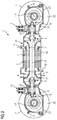
- FIG. 1 shows a longitudinal section of a double-axle drive, which is suitable both as a center drive and as an external longitudinal drive, especially for low-floor vehicles.
- a drive motor 3 is arranged between two drive axles 14, which has a stator lamination stack 4 and a rotor lamination stack 5 surrounding a rotor shaft 7.
- the rotatable about a rotation axis 6 rotor shaft 7 is mounted on bearings 9.
- the laminated stator core 4 is housed in a rotationally fixed manner in a housing unit 15.
- the housing unit 15 is divided into two housing sections 16 and 17, which can be connected to one another at a flange surface 10.
- the flange surface 10 of the flange is in the region of the laminated stator core 4.
- housing sections 16, 17 are each parts of the drive motor 3, clutch 8, bearing unit 23 for transmission 18 and drive motor 3.
- At least one of the housing sections 16, 17 may also be a brake, in particular between the clutch 8 and drive motor 3.
- On or in the housing sections 16, 17 optionally air guiding devices for cooling air flows, as well as coolant inlets 11 and coolant outlets 12 can be provided on the shell of the housing sections 16, 17.
- the flange surfaces 10 of the flange are axially outside of the stator lamination stack 4.
- the stator lamination stack 4 has a continuous seat in a housing section. This simplifies the demountability of the Housing sections 16, 17.
- electrical connections of the winding system of the drive motor 3 can be arranged particularly low on one side of the stator lamination 4 accessible.
- the housing portion 16 is u.a. the traction motor 3, the clutch 8, a bearing unit 23 for transmission 18 and traction motor 3 and optionally arranged a brake.
- the clutch 8 and a bearing unit 23 for the transmission 18 is arranged.
- air guide devices for cooling air flows, as well as coolant inlets 11 and coolant outlets 12, respectively, can optionally be provided on the casing of the housing sections 16, 17.
- each air inlets 11 and / or air outlets 12 in the wall of the housing sections 16, 17 are provided.
- a clutch 8 both to a driving axis 14 and to the other driving axis 14 toward arranged.
- the entire housing unit 15 is placed over springs 13 in a bogie, not shown, of a rail vehicle.
- the respective housing sections 16, 17 also respectively receive the bearing assemblies 23 in corresponding bearing seats of the housing sections 16, 17, which are preferably located between the transmission 18 and the coupling 8.
- the respective housing sections 16, 17 protrude axially - viewed from the traction motor 3 - via the drive axles 14.
- the housing sections 16, 17 thereby engage around their respective drive axle 14 both FIG. 1 as well as after FIG. 2 up to 180 degrees.
- an imaginary extension of the flange surfaces of the flanges 21 passes through the respective drive shaft 14.
- the housing sections 16, 17 are each closed by a gear cover 20, which are fastened by means of flange 21 on the respective housing portion 16, 17.
- the gear cover 20 each have a maintenance opening 22.
- a gear 18 each have a wheel or a wheel with two wheels.
- the drive axle of these wheels or wheelsets run essentially perpendicular to the axis of rotation 6 of the drive motor 3.
Abstract
Die Erfindung betrifft einen Doppelachsantrieb zumindest mit einem zwischen zwei Treibachsen (14) angeordneten Fahrmotor (3), dessen Drehachse (6) quer, insbesondere senkrecht zu den Treibachsen (14) verläuft, wobei mittels einer Antriebswelle (7) des Fahrmotors (3) jeweils über ein Getriebe (18) eine Radsatzwelle antreibbar ist, wobei der gesamte Doppelachsantrieb in einer Gehäuseeinheit (15) angeordnet ist, die zwei Gehäuseteile (16,17) aufweist.The invention relates to a Doppelachsantrieb at least one between two drive axles (14) arranged traction motor (3) whose axis of rotation (6) transversely, in particular perpendicular to the drive axles (14), wherein by means of a drive shaft (7) of the drive motor (3) respectively a wheel set shaft can be driven via a gear (18), wherein the entire double-axle drive is arranged in a housing unit (15) which has two housing parts (16, 17).
Description
Die Erfindung betrifft einen Doppelachsantrieb und ein Fahrwerk eines Schienenfahrwerks.The invention relates to a Doppelachsantrieb and a chassis of a rail chassis.
Bei Schienenfahrzeugen mit Längsantrieben, Mittenantrieben oder je einem außenliegenden Längsantrieb, also sogenannten Doppelachsantrieben, werden an einem Fahrmotor an seinen jeweiligen Enden seiner Rotorwelle ein Achsgetriebe montiert als Antrieb eines Rades oder Radsatzes, wodurch eine mehrteilige Gehäusekonstruktion entsteht.In rail vehicles with longitudinal drives, center drives or one external longitudinal drive, so-called Doppelachsantrieben, a axle drive are mounted on a traction motor at its respective ends of its rotor shaft as drive a wheel or wheelset, creating a multi-part housing construction.
Das Gehäuse des Fahrmotors dieses Längsantriebs beinhaltet bisher lediglich ein Lagerschild, wobei die Getriebe jeweils ein eigenes Gehäuse mit Getriebedeckel aufweisen und somit die gesamte Konstruktion des Doppelachsantriebs aus mehreren Teilen, insbesondere Gehäuseteilen, besteht, wie dies beispielsweise der
Ausgehend davon liegt der Erfindung die Aufgabe zugrunde, einen derartigen Doppelachsantrieb bezüglich seines Aufbaus zu vereinfachen und ein dementsprechendes Fahrwerk für ein Schienenfahrzeug zu schaffen.Based on this, the present invention seeks to simplify such a double-axle drive with respect to its structure and to create a corresponding chassis for a rail vehicle.
Die Lösung der gestellten Aufgabe gelingt durch einen Doppelachsantrieb zumindest mit einem zwischen zwei Treibachsen angeordneten Fahrmotor, dessen Drehachse quer, insbesondere senkrecht zu den Treibachsen verläuft, wobei mittels einer Antriebswelle des Fahrmotors jeweils über ein Getriebe eine Radsatzwelle antreibbar ist, wobei der gesamte Doppelachsantrieb in einer Gehäuseeinheit angeordnet ist, die zwei Gehäuseabschnitte aufweist.The solution of the problem is achieved by a Doppelachsantrieb at least with a arranged between two drive axles traction motor whose axis of rotation transversely, in particular perpendicular to the drive axles, by means of a drive shaft of the drive motor via a gear a wheelset is driven, the entire Doppelachsantrieb in a Housing unit is arranged, which has two housing sections.
Die Lösung der gestellten Aufgabe gelingt auch durch ein Fahrwerk eines Schienenfahrzeugs mit zumindest zwei parallelen Doppelachsantrieben, die durch wenigstens einen Längsträger miteinander mechanisch verbunden sind.The solution of the problem is also achieved by a chassis of a rail vehicle with at least two parallel Double-axis drives, which are mechanically connected to each other by at least one longitudinal member.
Erfindungsgemäß ist nunmehr zwischen den beiden Treibachsen lediglich nur noch eine Gehäuseeinheit vorgesehen, die nunmehr Bestandteile des Fahrmotors, des Lagers, der Kupplung und zwei Getrieben beinhaltet, so dass die Herstell- und Montagekosten und auch das Gewicht gegenüber herkömmlichen Doppelachsantrieben reduziert wird.According to the invention, only one housing unit is now provided between the two drive axles, which now contains components of the traction motor, the bearing, the clutch and two transmissions, so that the manufacturing and assembly costs and also the weight compared to conventional double-axle drives is reduced.
Vorteilhafterweise ist dabei das Getriebe als Hypoidkegelradgetriebe oder als normales Winkelgetriebe ausgeführt. Diese kompakten Getriebe eignen sich insbesondere für derartige Doppelachsantriebe, da sich dort der Kraftfluss auf engstem Raum nahezu ideal umlenken lässt. Um nun die beiden Gehäuseabschnitte kraftschlüssig miteinander zu verbinden, werden an den Stoßstellen Flanschflächen ausgeführt, an denen diese beiden Gehäuseabschnitte verbindbar sind.Advantageously, the gear is designed as Hypoidkegelradgetriebe or as a normal angle gear. These compact transmissions are particularly suitable for such double-axle drives, since there the force flow can be almost perfectly redirected in a confined space. In order to connect the two housing sections with one another in a force-fitting manner, flange surfaces are realized at the butt joints, to which these two housing sections can be connected.
Vorteilhafterweise verlaufen diese Flanschflächen senkrecht zur Antriebswelle des Rotors des Fahrmotors oder parallel zu den Treibachsen. Damit vereinfacht sich die Herstellung derartiger Flanschflächen.Advantageously, these flange surfaces are perpendicular to the drive shaft of the rotor of the drive motor or parallel to the drive axles. This simplifies the production of such flange surfaces.
Um dem Statorblechpaket des Fahrmotors einen durchgehenden Sitz im Gehäuse zu gewährleisten, werden die Flanschflächen außerhalb, insbesondere axial außerhalb des Statorblechpakets vorgesehen. Damit vereinfacht sich auch der Schrumpfsitz des Statorblechpakets innerhalb des dafür vorgesehenen Gehäuseabschnitts. Die auf das Statorblechpaket wirkenden Drehmomente Im Betrieb des Doppelachsantriebs werden dadurch besser aufgenommen. Dabei bleibt auch die Demontierbarkeit der jeweiligen Gehäuseabschnitte erhalten.In order to ensure the stator laminated core of the traction motor a continuous seat in the housing, the flange surfaces are provided outside, in particular axially outside the stator lamination. This also simplifies the shrink fit of the laminated stator core within the housing section provided for this purpose. The torques acting on the laminated stator core are better absorbed during operation of the twin-axle drive. In this case, the disassembly of the respective housing sections is retained.
Bei einem Fahrwerk eines Schienenfahrzeugs mit zumindest einem Doppelachsantrieb werden nunmehr ein kompakter Aufbau bei vergleichsweise geringem Gewicht und eine Kostenreduktion für derartige Fahrwerke geschaffen.In a chassis of a rail vehicle with at least a double axle now a compact design with relatively low weight and a cost reduction for such trolleys are created.
Die Erfindung sowie weitere vorteilhafte Ausgestaltungen der Erfindung werden anhand prinzipiell dargestellter Ausführungsbespiele näher dargestellt; dabei zeigt
- FIG 1
- einen Längsschnitt mit mittig einem angeordnetem Flansch,
- FIG 2
- einen Längsschnitt mit einem außermittig angeordnetem Flansch.
- FIG. 1
- a longitudinal section with a centrally arranged flange,
- FIG. 2
- a longitudinal section with an eccentrically arranged flange.
In den Gehäuseabschnitten 16, 17 sind dabei jeweils Teile des Fahrmotors 3, Kupplung 8, Lagereinheit 23 für Getriebe 18 und Fahrmotors 3. In zumindest einem der Gehäuseabschnitte 16, 17 kann außerdem eine Bremsen, insbesondere zwischen Kupplung 8 und Fahrmotor 3 angeordnet sein. Am bzw. in den Gehäuseabschnitten 16, 17 können optional Luftleitvorrichtungen für Kühlluftströme, als auch Kühlmitteleinlässe 11 bzw. Kühlmittelauslässe 12 an der Hülle der Gehäuseabschnitte 16, 17 vorgesehen werden.In the
In einer vorteilhaften weiteren, Ausführungsform gemäß
In dem Gehäuseabschnitt 16 ist dabei u.a. der Fahrmotor 3, die Kupplung 8, eine Lagereinheit 23 für Getriebe 18 und Fahrmotors 3 und optional eine Bremse angeordnet. Im anderen Gehäuseabschnitt 17 ist die Kupplung 8 und eine Lagereinheit 23 für das Getriebe 18 angeordnet. Am bzw. in den Gehäuseabschnitten 16, 17 können dabei jeweils optional Luftleitvorrichtungen für Kühlluftströme, als auch Kühlmitteleinlässe 11 bzw. Kühlmittelauslässe 12 an der Hülle der Gehäuseabschnitte 16, 17 vorgesehen werden.In the
In der Gehäuseeinheit 15, insbesondere in den Gehäuseabschnitten 16 und 17 sind somit jeweils Lufteinlässe 11 und/oder Luftauslässe 12 in der Wandung der Gehäuseabschnitte 16, 17 vorgesehen. Ebenso ist innerhalb der Gehäuseeinheit 15 jeweils eine Kupplung 8, sowohl zur einen Treibachse 14 als auch zur anderen Treibachse 14 hin, angeordnet. Die gesamte Gehäuseeinheit 15 ist über Federn 13 in einem nicht näher dargestellten Drehgestell eines Schienenfahrzeugs platziert.In the
Die jeweiligen Gehäuseabschnitte 16, 17 nehmen ebenso jeweils die Lageranordnungen 23 in dementsprechenden Lagersitzen der Gehäuseabschnitte 16, 17 auf, die sich vorzugsweise zwischen Getriebe 18 und Kupplung 8 befinden.The
Die jeweiligen Gehäuseabschnitte 16, 17 ragen axial - vom Fahrmotor 3 aus betrachtet - über die Treibachsen 14. Die Gehäuseabschnitte 16, 17 umgreifen dabei ihre jeweilige Treibachse 14 sowohl nach
Auch Winkel kleiner 180 Grad gestatten eine vergleichsweise einfache Montage.Even angles smaller than 180 degrees allow a comparatively simple installation.
Die Gehäuseabschnitte 16, 17 werden jeweils durch einen Getriebedeckel 20 abgeschlossen, die mittels Flanschverbindungen 21 am jeweiligen Gehäuseabschnitt 16, 17 befestigt werden. Die Getriebedeckel 20 weisen jeweils eine Wartungsöffnung 22 auf.The
Über die Treibachse 14 wird mittels eines Getriebes 18 jeweils ein Rad bzw. ein Radsatz mit zwei Rädern angetrieben. Die Treibachse dieser Räder bzw. dieser Radsätze verlaufen dabei im Wesentlichen senkrecht zur Drehachse 6 des Fahrmotors 3.About the
Claims (5)
Priority Applications (7)
| Application Number | Priority Date | Filing Date | Title |
|---|---|---|---|
| EP16152694.2A EP3199418A1 (en) | 2016-01-26 | 2016-01-26 | Dual axle drive |
| RU2018127323A RU2693178C1 (en) | 2016-01-26 | 2017-01-11 | Biaxial drive |
| EP17700642.6A EP3380380B1 (en) | 2016-01-26 | 2017-01-11 | Dual axle drive |
| ES17700642T ES2964751T3 (en) | 2016-01-26 | 2017-01-11 | Dual shaft drive |
| US16/072,743 US11046337B2 (en) | 2016-01-26 | 2017-01-11 | Double axle drive |
| PCT/EP2017/050464 WO2017129404A1 (en) | 2016-01-26 | 2017-01-11 | Double axle drive |
| CN201780008257.3A CN108602518A (en) | 2016-01-26 | 2017-01-11 | Two axle drive device |
Applications Claiming Priority (1)
| Application Number | Priority Date | Filing Date | Title |
|---|---|---|---|
| EP16152694.2A EP3199418A1 (en) | 2016-01-26 | 2016-01-26 | Dual axle drive |
Publications (1)
| Publication Number | Publication Date |
|---|---|
| EP3199418A1 true EP3199418A1 (en) | 2017-08-02 |
Family
ID=55273130
Family Applications (2)
| Application Number | Title | Priority Date | Filing Date |
|---|---|---|---|
| EP16152694.2A Withdrawn EP3199418A1 (en) | 2016-01-26 | 2016-01-26 | Dual axle drive |
| EP17700642.6A Active EP3380380B1 (en) | 2016-01-26 | 2017-01-11 | Dual axle drive |
Family Applications After (1)
| Application Number | Title | Priority Date | Filing Date |
|---|---|---|---|
| EP17700642.6A Active EP3380380B1 (en) | 2016-01-26 | 2017-01-11 | Dual axle drive |
Country Status (6)
| Country | Link |
|---|---|
| US (1) | US11046337B2 (en) |
| EP (2) | EP3199418A1 (en) |
| CN (1) | CN108602518A (en) |
| ES (1) | ES2964751T3 (en) |
| RU (1) | RU2693178C1 (en) |
| WO (1) | WO2017129404A1 (en) |
Citations (4)
| Publication number | Priority date | Publication date | Assignee | Title |
|---|---|---|---|---|
| DE3047413A1 (en) * | 1980-12-17 | 1982-07-01 | Thyssen Industrie Ag, 4300 Essen | DOUBLE AXLE DRIVE FOR RAIL VEHICLES |
| DE3217301A1 (en) * | 1982-05-05 | 1983-11-17 | Licentia Patent-Verwaltungs-Gmbh, 6000 Frankfurt | Drive for electric rail locomotives |
| DE8814798U1 (en) * | 1988-11-28 | 1990-03-29 | Siemens Ag, 1000 Berlin Und 8000 Muenchen, De | |
| EP0718170A1 (en) | 1994-12-22 | 1996-06-26 | Siemens Aktiengesellschaft | Bogie for railway vehicles |
Family Cites Families (19)
| Publication number | Priority date | Publication date | Assignee | Title |
|---|---|---|---|---|
| US3014433A (en) * | 1958-06-25 | 1961-12-26 | Durand Francois | Two-axle drive for trams and other vehicles |
| AT292777B (en) * | 1968-06-12 | 1971-09-10 | Maschf Augsburg Nuernberg Ag | Drive for two or more axle motor bogies of rail vehicles |
| DE6750770U (en) * | 1968-07-16 | 1969-01-16 | Rheinstahl Huettenwerke Ag | DOUBLE AXLE DRIVE FOR RAIL VEHICLES |
| US4148262A (en) * | 1973-05-22 | 1979-04-10 | Carl Hurth Maschinen-Und Zahnradfabrik | Railway vehicle drive |
| US3859929A (en) * | 1973-09-06 | 1975-01-14 | Rheinstahl Ag | Resilient double axle railway car drive |
| DE2514265C3 (en) * | 1975-03-27 | 1979-06-13 | Siemens Ag, 1000 Berlin Und 8000 Muenchen | Drive for an electric rail vehicle |
| DE2853839A1 (en) * | 1978-12-13 | 1980-06-19 | Hurth Masch Zahnrad Carl | DOUBLE-AXLE DRIVE FOR BOGIE ROTATORS |
| DE2933706B2 (en) * | 1979-08-21 | 1981-07-02 | Thyssen Industrie Ag, 4300 Essen | Bogie for rail vehicles, e.g. trams |
| DE3026756A1 (en) * | 1980-07-15 | 1982-05-27 | Carl Hurth Maschinen- und Zahnradfabrik GmbH & Co, 8000 München | DOUBLE AXLE DRIVE FOR BOGIE BOGIES |
| DE3030594A1 (en) * | 1980-08-11 | 1982-02-18 | Siemens AG, 1000 Berlin und 8000 München | DRIVE UNIT FOR THE DRIVE AXLES OF RAIL VEHICLES |
| DE3047412A1 (en) * | 1980-12-17 | 1982-07-15 | Thyssen Industrie Ag, 4300 Essen | DISC BRAKE ARRANGEMENT ON A RAIL VEHICLE |
| DE3140167A1 (en) * | 1981-10-08 | 1983-04-28 | Siemens AG, 1000 Berlin und 8000 München | DOUBLE AXLE LENGTH DRIVE FOR AN ELECTRIC RAIL DRIVE VEHICLE |
| DE3149471A1 (en) * | 1981-12-14 | 1983-06-23 | Thyssen Industrie Ag, 4300 Essen | DOUBLE AXLE DRIVE FOR RAIL VEHICLES |
| DE3479992D1 (en) * | 1983-10-17 | 1989-11-09 | Hurth Masch Zahnrad Carl | Drive unit for railway vehicles |
| DE3403910A1 (en) * | 1984-02-04 | 1985-08-08 | Thyssen Industrie Ag, 4300 Essen | CARDANIC DOUBLE COUPLING |
| DE3514124A1 (en) * | 1984-09-14 | 1986-03-20 | Thyssen Industrie Ag, 4300 Essen | CARDANIC DOUBLE COUPLING |
| DE3600675A1 (en) * | 1986-01-13 | 1987-07-16 | Flender A F & Co | Double axle drive for rail vehicles |
| DE3624684A1 (en) * | 1986-07-22 | 1988-01-28 | Bergische Stahlindustrie | Double axle drive with mechanical axle decoupling |
| DE10354141A1 (en) | 2003-11-19 | 2005-06-23 | Voith Turbo Gmbh & Co. Kg | Powered chassis for rail vehicles, especially bogies for low floor vehicles |
-
2016
- 2016-01-26 EP EP16152694.2A patent/EP3199418A1/en not_active Withdrawn
-
2017
- 2017-01-11 ES ES17700642T patent/ES2964751T3/en active Active
- 2017-01-11 CN CN201780008257.3A patent/CN108602518A/en active Pending
- 2017-01-11 US US16/072,743 patent/US11046337B2/en active Active
- 2017-01-11 WO PCT/EP2017/050464 patent/WO2017129404A1/en active Application Filing
- 2017-01-11 RU RU2018127323A patent/RU2693178C1/en active
- 2017-01-11 EP EP17700642.6A patent/EP3380380B1/en active Active
Patent Citations (4)
| Publication number | Priority date | Publication date | Assignee | Title |
|---|---|---|---|---|
| DE3047413A1 (en) * | 1980-12-17 | 1982-07-01 | Thyssen Industrie Ag, 4300 Essen | DOUBLE AXLE DRIVE FOR RAIL VEHICLES |
| DE3217301A1 (en) * | 1982-05-05 | 1983-11-17 | Licentia Patent-Verwaltungs-Gmbh, 6000 Frankfurt | Drive for electric rail locomotives |
| DE8814798U1 (en) * | 1988-11-28 | 1990-03-29 | Siemens Ag, 1000 Berlin Und 8000 Muenchen, De | |
| EP0718170A1 (en) | 1994-12-22 | 1996-06-26 | Siemens Aktiengesellschaft | Bogie for railway vehicles |
Also Published As
| Publication number | Publication date |
|---|---|
| CN108602518A (en) | 2018-09-28 |
| EP3380380C0 (en) | 2023-09-06 |
| WO2017129404A1 (en) | 2017-08-03 |
| RU2693178C1 (en) | 2019-07-01 |
| ES2964751T3 (en) | 2024-04-09 |
| US20190031212A1 (en) | 2019-01-31 |
| EP3380380B1 (en) | 2023-09-06 |
| EP3380380A1 (en) | 2018-10-03 |
| US11046337B2 (en) | 2021-06-29 |
Similar Documents
| Publication | Publication Date | Title |
|---|---|---|
| EP1338077B1 (en) | Retarder, particularly provided as a braking device or auxiliary braking device for vehicles or the like, especially rail vehicles | |
| EP2601086B1 (en) | Drive motor with cooling system | |
| WO2006106086A1 (en) | Electric machine comrpising a housing for liquid cooling | |
| DE102005055690A1 (en) | Motor drive for vehicle, has electrical driving motor with rotor, which is radially arranged in the stator whereby differential gear is arranged inside rotor | |
| DE10047911A1 (en) | Drive a wheelset | |
| EP3186127B1 (en) | Railway drive with braking device | |
| EP3713805A1 (en) | Bogie of a rail vehicle | |
| EP0582563B1 (en) | Direct drive for a wheel of a railway vehicle | |
| EP1247713B1 (en) | Driven running gear without wheelsets for railway vehicles | |
| DE102009000712A1 (en) | Driving axle for electric fork-lift truck, has drive shaft connected with differential gear unit at side of drive device, supported between drive device and brake device, and supported in housing device in region of differential gear unit | |
| EP0760305B1 (en) | Single wheel drive for an electrically driven vehicle | |
| EP0052244B1 (en) | Bogie for rail vehicles like trams | |
| DE2606807B2 (en) | Electric motor for output on both sides | |
| EP1572487A1 (en) | Wheel hub drive | |
| EP0542171A1 (en) | Power unit for railway traction units | |
| EP3380380B1 (en) | Dual axle drive | |
| EP0077290B1 (en) | Longitudinal tandem drive unit for an electric rail vehicle | |
| DE4303069C1 (en) | Electric motor direct drive for steerable individual wheel for rail vehicle - is located on at least one horizontally swivelable wheel carrier and external rotor motor, provided as direct drive axially near to individual wheel. | |
| DE102019211172B4 (en) | Single axle drive and rail vehicle | |
| EP3450784B1 (en) | Plug coupling for drives | |
| EP0878368B1 (en) | Drive unit for railway vehicles | |
| DE19602119C1 (en) | Single wheel drive for electrically powered vehicle, esp. for low level rail vehicle, e.g. tram | |
| DE19922648A1 (en) | Electric wheel drive for vehicles, preferably for rail vehicles has electric motor on wheel with winding on carrier connected rigidly with vehicle carrier part so that winding is inside wheel | |
| EP0054134A1 (en) | Double axle drive for rail vehicles | |
| DE102022114472A1 (en) | Axial flow machine, electric final drive train and motor vehicle |
Legal Events
| Date | Code | Title | Description |
|---|---|---|---|
| PUAI | Public reference made under article 153(3) epc to a published international application that has entered the european phase |
Free format text: ORIGINAL CODE: 0009012 |
|
| AK | Designated contracting states |
Kind code of ref document: A1 Designated state(s): AL AT BE BG CH CY CZ DE DK EE ES FI FR GB GR HR HU IE IS IT LI LT LU LV MC MK MT NL NO PL PT RO RS SE SI SK SM TR |
|
| AX | Request for extension of the european patent |
Extension state: BA ME |
|
| RAP1 | Party data changed (applicant data changed or rights of an application transferred) |
Owner name: SIEMENS AKTIENGESELLSCHAFT |
|
| STAA | Information on the status of an ep patent application or granted ep patent |
Free format text: STATUS: THE APPLICATION IS DEEMED TO BE WITHDRAWN |
|
| 18D | Application deemed to be withdrawn |
Effective date: 20180203 |