EP0052244B1 - Bogie for rail vehicles like trams - Google Patents
Bogie for rail vehicles like trams Download PDFInfo
- Publication number
- EP0052244B1 EP0052244B1 EP81108469A EP81108469A EP0052244B1 EP 0052244 B1 EP0052244 B1 EP 0052244B1 EP 81108469 A EP81108469 A EP 81108469A EP 81108469 A EP81108469 A EP 81108469A EP 0052244 B1 EP0052244 B1 EP 0052244B1
- Authority
- EP
- European Patent Office
- Prior art keywords
- bogie
- motor
- bogies
- angular
- pivots
- Prior art date
- Legal status (The legal status is an assumption and is not a legal conclusion. Google has not performed a legal analysis and makes no representation as to the accuracy of the status listed.)
- Expired
Links
Images
Classifications
-
- B—PERFORMING OPERATIONS; TRANSPORTING
- B61—RAILWAYS
- B61C—LOCOMOTIVES; MOTOR RAILCARS
- B61C9/00—Locomotives or motor railcars characterised by the type of transmission system used; Transmission systems specially adapted for locomotives or motor railcars
- B61C9/38—Transmission systems in or for locomotives or motor railcars with electric motor propulsion
- B61C9/48—Transmission systems in or for locomotives or motor railcars with electric motor propulsion with motors supported on vehicle frames and driving axles, e.g. axle or nose suspension
- B61C9/50—Transmission systems in or for locomotives or motor railcars with electric motor propulsion with motors supported on vehicle frames and driving axles, e.g. axle or nose suspension in bogies
-
- B—PERFORMING OPERATIONS; TRANSPORTING
- B61—RAILWAYS
- B61C—LOCOMOTIVES; MOTOR RAILCARS
- B61C9/00—Locomotives or motor railcars characterised by the type of transmission system used; Transmission systems specially adapted for locomotives or motor railcars
- B61C9/38—Transmission systems in or for locomotives or motor railcars with electric motor propulsion
- B61C9/52—Transmission systems in or for locomotives or motor railcars with electric motor propulsion with transmission shafts at an angle to the driving axles
-
- B—PERFORMING OPERATIONS; TRANSPORTING
- B61—RAILWAYS
- B61F—RAIL VEHICLE SUSPENSIONS, e.g. UNDERFRAMES, BOGIES OR ARRANGEMENTS OF WHEEL AXLES; RAIL VEHICLES FOR USE ON TRACKS OF DIFFERENT WIDTH; PREVENTING DERAILING OF RAIL VEHICLES; WHEEL GUARDS, OBSTRUCTION REMOVERS OR THE LIKE FOR RAIL VEHICLES
- B61F3/00—Types of bogies
- B61F3/02—Types of bogies with more than one axle
- B61F3/04—Types of bogies with more than one axle with driven axles or wheels
Definitions
- the invention relates to a bogie for rail vehicles, such as trams, with horizontally pivotably held in the cross member by vertical pins and interconnected by tie rods half bogies (pendulum frame), in which the vertically resilient running wheels each with a bevel gear movable with them and independently of the opposite impellers are driven.
- the invention has for its object to develop the drive for the bogie according to the aforementioned document, so that smaller engine dimensions and transmission parts can be used in a smaller number. There should also be a good installation option.
- the cross member is connected in a universal joint-like manner to the half-bogies by means of the pins and is supported on them by means of spring elements arranged on both sides of the pins, and a single motor, each with a counter-rotating inner rotor and outer rotor, is arranged laterally on each half-bogie, between the angular gears, wherein the inner and outer rotors are provided flying on elongated pinion shafts of the angular gear.
- an electric motor with an inner rotor and an outer rotor rotating in opposite directions is known for driving vehicles. But it drives coaxial impellers, for which a reversing device of the direction of rotation is essential for one of the impellers.
- Another proposal for the drive of two pendulum frames of a bogie is to connect the cross member via the pins in a universal joint-like manner to the pendulum frames (half-bogies) and to support them by means of spring elements arranged on both sides of the pins and to provide the drives in a stationary manner on the cross member.
- this proposal known from European patent application 0 025 484, was not published before the priority date of the present patent application.
- the inventive connection of the half bogies to the cross member via universal joints makes it possible that an electric motor with two counter-rotating rotors can be used without a reverse gear for driving two wheels of the same side of the vehicle in a weight-saving design.
- the universal joint-like connection opens the possibility of also fixing the motor to the semi-bogie, so that the latter can now be functionally assembled together with the angular gears and prefabricated as a section of a bogie and kept in stock. Thanks to the two rotors, the motor is considerably smaller and lighter than a conventional motor with the same speed.
- the rotors rotate against each other at a relative speed of 6000 rpm, which leads to smaller dimensions of the electrical part.
- the angular gear can have approximately the same reduction ratio as the aforementioned known planetary gear, the same reduction ratio and thus the same driving speed are achieved overall with fewer transmission elements. Due to the flying arrangement of the rotors on the pinion shafts, the rotors are still mounted in bearings of the angular gear lubricated with circulating oil, so that adequate lubrication is always guaranteed in a proven manner.
- the cross member 1 of a bogie is provided on each side with a pin 2 running vertically downwards.
- the pins 2 engage in a sleeve 3, which are articulated in the middle of the half bogies 4 transversely to the direction of travel.
- Two bolts 5 are used for this purpose, which are inserted in the racks and engage laterally in the bushes 3.
- the semi-bogies 4 can also perform a vertical tilting movement around the bolts 5 in addition to a horizontal pivoting movement about the pin 2. So that the horizontal pivoting movement that occurs when driving through curves is the same for both half-bogies 4, these are connected to one another by two tie rods 7.
- the wheel bearings are divided vertically so that the wheels 9 can be removed without having to lift the car.
- the division area is covered with a cover 13.
- the body 10 On the cross member 1, the body 10 is supported on both sides by a further spring 11 (air spring), which can also be a hydraulic spring. Handlebars 12 serve to hold the car body 10 against the driving and braking forces on the cross member 1.
- air spring air spring
- Handlebars 12 serve to hold the car body 10 against the driving and braking forces on the cross member 1.
- a motor gear unit 6 is arranged on the inside, consisting of two angular gears 14 which drive the wheels 9 and an intermediate motor 15, each of which has an inner rotor 15a and outer rotor 15b which rotate in opposite directions and which are mounted on extended pinion shafts 16 Angular gear 14 are arranged on the fly.
- the pinion shafts 16 are particularly well suited for precise centering of the rotors 15a and 15b because of their large bearing length.
- the bevel gears 17 of the angular gear 14 are placed directly on the axles 18 of the impellers 9, so that special couplings can be omitted.
- the housing (casing) of the motor 15 is vertically divided approximately in the middle at 15c, the two parts 15d and 15e being made in one piece with the housings of the angular gear 14.
- This design enables the rotors 15a and 15b to be aligned precisely with respect to one another to a minimal air gap in a simple manner. Both parts 15d and 15e are connected to one another by flanges 15f.
- the housing parts 15d and 15e of the motor 15 are additionally connected to the semi-bogie 4 at 19.
- the housing of the motor gear unit 6 is also horizontally divided in the center of the axis of the impellers 9, the halves being connected by means of flanges 20.
Abstract
Description
Die Erfindung bezieht sich auf ein Drehgestell für Schienenfahrzeuge, wie Straßenbahnen, mit im Querträger durch senkrechte Zapfen horizontal schwenkbar gehaltenen und durch Spurstangen miteinander verbundenen Halbdrehgestellen (Pendelrahmen), in denen die senkrecht federnden Laufräder über je ein zusammen mit ihnen bewegliches Winkelgetriebe und unabhänig von den gegenüberliegenden Laufrädern angetrieben sind.The invention relates to a bogie for rail vehicles, such as trams, with horizontally pivotably held in the cross member by vertical pins and interconnected by tie rods half bogies (pendulum frame), in which the vertically resilient running wheels each with a bevel gear movable with them and independently of the opposite impellers are driven.
Ein derartiges Drehgestell ist bereits in der DE-A-2 913 539 erwähnt. Bei solchen Drehgestellen sind die zwei horizontal schenkbaren und zueinander parallel geführten Pendelrahmen (Halbdrehgestelle), wie üblich, durch die senkrechten Zapfen mit dem Querträger verbunden. Für die Abfederung der Laufräder sind an den Enden der Halbdrehgestelle senkrecht angelenkte Schwingen vorgesehen, an denen das Winkelgetriebe angeflanscht ist, so daß es über die Schwinge die Bewegungen des Laufrades zwangsläufig mitmacht. Um schnell laufende, d. h. verhältnismäßig kleine Motoren verwenden zu können, ist allerdings ein weiteres Getriebe vorgesehen, das zu dem Winkelgetriebe in Reihegeschaltetund in der Nabe des Laufrades angeordnet ist. Dieser Antrieb ist wegen der Vielzahl der Übertragungsteile alsaufwendiganzusehen.Such a bogie is already mentioned in DE-A-2 913 539. In such bogies, the two horizontally pivotable and mutually parallel pendulum frames (half bogies), as usual, are connected to the cross member by the vertical pins. For the suspension of the impellers vertically articulated rockers are provided at the ends of the half bogies, on which the angular gear is flanged, so that it inevitably participates in the movements of the impeller via the rocker. In order to run fast, i.e. H. To be able to use relatively small motors, however, another gear is provided, which is connected in series with the angular gear and arranged in the hub of the impeller. This drive can be regarded as complex because of the large number of transmission parts.
Der Erfindung liegt die Aufgabe zugrunde, den Antrieb für das Drehgstell gemäß der vorgenannten Druckschrift weiter zu entwickeln, so daß kleinere Motorabmessungen und Übertragungsteile in geringerer Anzahl in Anwendung kommen können. Auch soll eine gute Montagemöglichkeit gegeben sein.The invention has for its object to develop the drive for the bogie according to the aforementioned document, so that smaller engine dimensions and transmission parts can be used in a smaller number. There should also be a good installation option.
Zur Lösung dieser Aufgabe ist der Querträger über die Zapfen kreuzgelenkartig mit den Halbdrehgestellen verbunden und auf ihnen mittels beiderseits der Zapfen angeordneter Federelemente abgestützt und ein einziger Motor mit je einem sich gegenläufig drehenden inneren Rotor und äußeren Rotor an jedem Halbdrehgestell seitlich, zwischen den Winkelgetrieben angeordnet, wobei der innere und der äußere Rotor auf verlängerten Ritzelwellen der Winkelgetriebe fliegend vorgesehen sind.To solve this problem, the cross member is connected in a universal joint-like manner to the half-bogies by means of the pins and is supported on them by means of spring elements arranged on both sides of the pins, and a single motor, each with a counter-rotating inner rotor and outer rotor, is arranged laterally on each half-bogie, between the angular gears, wherein the inner and outer rotors are provided flying on elongated pinion shafts of the angular gear.
Zum Antreiben von Fahrzeugen ist zwar nach der DE-C-856 309 ein Elektromotor mit je einem sich gegenläufig drehenden inneren Rotor und äußeren Rotor bekannt. Er treibt aber gleichachsige Laufräder an, wozu eine Umkehrvorrichtung der Drehrichtung für eines der Laufräder unerläßlich ist.According to DE-C-856 309, an electric motor with an inner rotor and an outer rotor rotating in opposite directions is known for driving vehicles. But it drives coaxial impellers, for which a reversing device of the direction of rotation is essential for one of the impellers.
Ein Vorschlag geht im übrigen bei dem Antrieb von zwei Pendelrahmen eines Drehgestells dahin, den Querträger über die Zapfen kreuzgelenkartig mit den Pendelrahmen (Halbdrehgestellen) zu verbinden und auf diesen mittels beiderseits der Zapfen angeordneter Federelemente abzustützen und die Antriebe ortsfest an dem Querträger vorzusehen. Abgesehen davon, daß hochtourige Elektromotoren bei diesem Antrieb nur unter Einschaltung von Planetengetrieben, die wohlgemerkt mehr Zahnräder haben als ein einstufiges Winkelgetriebe, verwendet werden können, ist dieser nach der europäischen Patentanmeldung 0 025 484 bekannte Vorschlag nicht vor dem Prioritätstage der vorliegenden Patentanmeldung veröffentlicht worden.Another proposal for the drive of two pendulum frames of a bogie is to connect the cross member via the pins in a universal joint-like manner to the pendulum frames (half-bogies) and to support them by means of spring elements arranged on both sides of the pins and to provide the drives in a stationary manner on the cross member. In addition to the fact that high-speed electric motors can only be used with this drive with the involvement of planetary gears, which, mind you, have more gears than a single-stage bevel gear, this proposal, known from European patent application 0 025 484, was not published before the priority date of the present patent application.
Der erfindungsgemäße Anschluß der Halbdrehgestelle an dem Querträger über Kreuzgelenke ermöglicht es überhaupt, daß ein Elektromotor mit zwei gegenläufigen Rotoren ohne Umkehrgetriebe für den Antrieb zweier Laufräder derselben Fahrzeugseite in gewichtssparender Bauweise verwendet werden kann. Außerdem eröffnet die kreuzgelenkartige Verbindung die Möglichkeit, auch den Motor an dem Halbdrehgestell festzulegen, so daß nunmehr das letztere zusammen mit den Winkelgetrieben funktionsfähig zusammengebaut und als Sektion eines Drehgestells vorgefertigt und auf Vorrat gehalten werden kann. Dank der zwei Rotoren fällt der Motor erheblich kleiner und leichter aus als ein konventioneller Motor mit gleicher Drehzahl. Um zum Beispiel eine Drehzahl von 3000 U/min an den Wellen zu erreichen, drehen sich die Rotoren mit einer Relativdrehzahl von 6000 U/min gegeneinander, was zu kleineren Abmessungen des elektrischen Teiles führt. Da das Winkelgetriebe etwa dasselbe Untersetzungsverhältnis aufweisen kann wie das vorgenannte, bekannte Planetengetriebe, wird im ganzen mit weniger Übertragungselementen das gleiche Untersetzungsverhältnis und damit die gleiche Fahrgeschwindigkeit erzielt. Durch die fliegende Anordnung der Rotoren auf den Ritzelwellen sind die Rotoren noch in mit Umlauföl geschmierten Lagern der Winkelgetriebe gelagert, so daß stets eine ausreichende Schmierung in bewährter Weise gewährleistet ist.The inventive connection of the half bogies to the cross member via universal joints makes it possible that an electric motor with two counter-rotating rotors can be used without a reverse gear for driving two wheels of the same side of the vehicle in a weight-saving design. In addition, the universal joint-like connection opens the possibility of also fixing the motor to the semi-bogie, so that the latter can now be functionally assembled together with the angular gears and prefabricated as a section of a bogie and kept in stock. Thanks to the two rotors, the motor is considerably smaller and lighter than a conventional motor with the same speed. For example, in order to achieve a speed of 3000 rpm on the shafts, the rotors rotate against each other at a relative speed of 6000 rpm, which leads to smaller dimensions of the electrical part. Since the angular gear can have approximately the same reduction ratio as the aforementioned known planetary gear, the same reduction ratio and thus the same driving speed are achieved overall with fewer transmission elements. Due to the flying arrangement of the rotors on the pinion shafts, the rotors are still mounted in bearings of the angular gear lubricated with circulating oil, so that adequate lubrication is always guaranteed in a proven manner.
Weitere wichtige Einzelheiten des Antriebs gehen aus den weiteren Ansprüchen und dem Ausführungsbeispiel hervor, das die Erfindung in den Zeichnungen schematisch veranschaulicht. Es zeigt
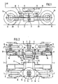
- Fig. 1 ein Drehgestell in Seitenansicht und
- Fig. 2 eine teilweise im Schnitt dargestellte Draufsicht des Drehgestelles.
- Fig. 1 shows a bogie in side view
- Fig. 2 is a partially sectioned plan view of the bogie.
Der Querträger 1 eines Drehgestells ist auf jeder Seite mit einem senkrecht nach unten verlaufenden Zapfen 2 versehen. Die Zapfen 2 greifen in je eine Büchse 3 ein, die in der Mitte der Halbdrehgestelle 4 quer zur Fahrtrichtung gelenkig gelagert sind. Dazu dienen je zwei Bolzen 5, die in den Gestellen stecken und seitlich in die Büchsen 3 eingreifen. Durch diese kardanische Halterung können die Halbdrehgestelle 4 neben einer horizontalen Schwenkbewegung um den Zapfen 2 noch eine vertikale Kippbewegung um die Bolzen 5 ausführen. Damit die horizontale Schwenkbewegung, die beim Durchfahren von Kurven eintritt, bei beiden Halbdrehgestellen 4 gleich ist, sind diese durch zwei Spurstangen 7 miteinanderverbunden.The
Zwischen dem Querträger 1 und den Halbdrehgestellen 4 sind in Fahrtrichtung beiderseits des Zapfens 2 Schraubenfedern 8 angeordnet, welche die beim Überfahren von Gleisunebenheiten auftretenden Kippbewegungen abfedern. Durch diese Anordnung wird die früher übliche Einzelfederung der Laufräder 9 ersetzt, so daß diese nunmehr fest in den Halbdrehgestellen 4 gelagert werden können.Between the
Die Radlager sind vertikal geteilt, damit die Laufräder 9 ausgebaut werden können, ohne den Wagen anheben zu müssen.The wheel bearings are divided vertically so that the
Der Teilungsbereich ist mit einem Deckel 13 abgedeckt.The division area is covered with a
Auf dem Querträger 1 ist der Wagenkasten 10 beiderseits durch je eine weitere Feder 11 (Luftfeder), die auch eine Hydraulikfeder sein kann, abgestützt. Lenker 12 dienen dazu, den Wagenkasten 10 gegenüber den Antriebs- und Bremskräften am Querträger 1 zu halten.On the
An jedem Halbdrehgestell 4 ist innen seitlich ein Motorgetriebe-Aggregat 6, bestehend aus zwei die Laufräder 9 antreibenden Winkelgetrieben 14 und einem dazwischenliegenden Motor 15 angeordnet, der je einen gegenläufig sich drehenden inneren Rotor 15a und äußeren Rotor 15b aufweist, die auf verlängerten Ritzelwellen 16 der Winkelgetriebe 14 fliegend angeordnet sind. Die Ritzelwellen 16 sind wegen ihrer großen Lagerlänge für eine genaue Zentrierung der Rotoren 15a und 15b besonders gut geeignet. Die Kegelräder 17 der Winkelgetriebe 14 sind unmittelbar auf die Achsen 18 der Laufräder 9 aufgesetzt, so daß besondere Kupplungen entfallen können.On each
Das Gehäuse (Verkleidung) des Motors 15 ist etwa in der Mitte bei 15c vertikal geteilt, wobei die beiden Teile 15d und 15e mit den Gehäusen der Winkelgetriebe 14 aus einem Stück bestehen. Diese Bauweise ermöglicht es, in einfacher Weise die Rotoren 15a und 15b genau gegeneinander auf einen minimalen Luftspalt auszurichten. Beide Teile 15d und 15e sind durch 'Flanschen 15f miteinander verbunden.The housing (casing) of the
Um Versetzungen der Winkelgetriebe 14 gegeneinander mit Sicherheit auszuschalten, sind die Gehäuseteile 15d und 15e des Motors 15 noch zusätzlich mit dem Halbdrehgestell 4 bei 19 verbunden.In order to ensure that displacements of the
Eine andere - nicht gezeichnete - Möglichkeit für eine sichere Ausrichtung des Motorgetriebe-Aggregates 6 am Halbdrehgestell 4 besteht auch darin, daß sowohl das Motorgehäuse 15d und 15e wie auch die Gehäuse der Winkelgetriebe 14 über Zentrierungen mit dem Halbdrehgestell 4 verbunden sind.Another possibility - not shown - for a safe alignment of the
Das Gehäuse des Motorgetriebe-Aggregates 6 ist ferner in Achsmitte der Laufräder 9 horizontal geteilt, wobei die Hälften mittels Flanschen 20 verbunden sind.The housing of the
Claims (5)
Priority Applications (1)
| Application Number | Priority Date | Filing Date | Title |
|---|---|---|---|
| AT81108469T ATE13163T1 (en) | 1980-11-14 | 1981-10-17 | BOGIE FOR RAIL VEHICLES, SUCH AS TRAMWAYS. |
Applications Claiming Priority (2)
| Application Number | Priority Date | Filing Date | Title |
|---|---|---|---|
| DE19803042987 DE3042987A1 (en) | 1980-11-14 | 1980-11-14 | Bogie for rail vehicles like trams |
| DE3042987 | 1980-11-14 |
Publications (2)
| Publication Number | Publication Date |
|---|---|
| EP0052244A1 EP0052244A1 (en) | 1982-05-26 |
| EP0052244B1 true EP0052244B1 (en) | 1985-05-08 |
Family
ID=6116784
Family Applications (1)
| Application Number | Title | Priority Date | Filing Date |
|---|---|---|---|
| EP81108469A Expired EP0052244B1 (en) | 1980-11-14 | 1981-10-17 | Bogie for rail vehicles like trams |
Country Status (3)
| Country | Link |
|---|---|
| EP (1) | EP0052244B1 (en) |
| AT (1) | ATE13163T1 (en) |
| DE (2) | DE3042987A1 (en) |
Cited By (1)
| Publication number | Priority date | Publication date | Assignee | Title |
|---|---|---|---|---|
| DE4305096A1 (en) * | 1993-02-19 | 1994-08-25 | Ruiter Ernest De | Drive for rail vehicles which is suitable for bends |
Families Citing this family (8)
| Publication number | Priority date | Publication date | Assignee | Title |
|---|---|---|---|---|
| DE3302639A1 (en) * | 1983-01-27 | 1984-08-02 | Thyssen Industrie Ag, 4300 Essen | DRIVE ROTATION FOR RAILWAY VEHICLES LIKE TRAMS |
| DE3437451A1 (en) * | 1984-10-12 | 1986-04-17 | Brown, Boveri & Cie Ag, 6800 Mannheim | Cover for electrical components |
| DE3732337A1 (en) * | 1987-09-25 | 1989-04-20 | Bergische Stahlindustrie | POWERED SINGLE-WHEEL CHASSIS FOR LOW-FLOOR CITY CARS OF DIFFERENT TRACK WIDTH |
| FR2624079B1 (en) * | 1987-12-03 | 1992-04-30 | Alsthom | BOGIE FOR RAIL VEHICLE WITH MECHANICAL DIFFERENTIAL TRANSMISSION |
| DE4429889A1 (en) * | 1994-08-24 | 1996-02-29 | Bergische Stahlindustrie | Powered undercarriage for rail vehicles |
| AT406569B (en) * | 1995-03-23 | 2000-06-26 | Elin Ebg Traction Gmbh | CHASSIS FOR A RAIL VEHICLE, IN PARTICULAR LOW-FLOOR TRAM |
| DE29508462U1 (en) * | 1995-05-24 | 1996-09-26 | Duewag Ag | Running gear for rail vehicles, especially low-floor light rail vehicles, and vehicle drive module equipped with them |
| DE19650913A1 (en) * | 1996-12-07 | 1998-06-10 | Sab Wabco Bsi Verkehrstechnik | Driven idler axle |
Citations (1)
| Publication number | Priority date | Publication date | Assignee | Title |
|---|---|---|---|---|
| EP0010619A1 (en) * | 1978-11-06 | 1980-05-14 | Thyssen Industrie Ag | Electric motor-and-gearbox drive unit for railway vehicles such as tramways or the like |
Family Cites Families (6)
| Publication number | Priority date | Publication date | Assignee | Title |
|---|---|---|---|---|
| CH279157A (en) * | 1949-03-14 | 1951-11-15 | Paschetto Alberto | Trolley with independent wheels for rail vehicles. |
| DE856309C (en) * | 1950-08-13 | 1952-11-20 | Steinbock G M B H | With its two axial ends for driving rotating parts that are not rigidly coupled, especially vehicle wheels, an electric motor |
| DE7243926U (en) * | 1972-11-30 | 1979-03-08 | O & K Orenstein & Koppel Ag, 1000 Berlin | ELECTRIC MOTORS FOR THE SIMULTANEOUS DRIVING OF TWO AXES STORED IN A RAILWAY BOGE |
| DE2910392A1 (en) * | 1979-03-16 | 1980-09-25 | Thyssen Industrie | Railway vehicle or tram bogie mounting - has mitre gears inside individually driven wheels on rocker arms |
| DE2913539A1 (en) * | 1979-04-04 | 1980-10-16 | Thyssen Industrie | Tram-car type driven wheeled bogie frame - has planetary gears in hubs with drive via mitre gears |
| DE2936771C2 (en) * | 1979-09-12 | 1982-11-18 | Thyssen Industrie Ag, 4300 Essen | Drive bogie for rail vehicles, e.g. trams |
-
1980
- 1980-11-14 DE DE19803042987 patent/DE3042987A1/en not_active Withdrawn
-
1981
- 1981-10-17 EP EP81108469A patent/EP0052244B1/en not_active Expired
- 1981-10-17 AT AT81108469T patent/ATE13163T1/en not_active IP Right Cessation
- 1981-10-17 DE DE8181108469T patent/DE3170416D1/en not_active Expired
Patent Citations (1)
| Publication number | Priority date | Publication date | Assignee | Title |
|---|---|---|---|---|
| EP0010619A1 (en) * | 1978-11-06 | 1980-05-14 | Thyssen Industrie Ag | Electric motor-and-gearbox drive unit for railway vehicles such as tramways or the like |
Non-Patent Citations (1)
| Title |
|---|
| Eisenbahn Technische Rundschau (26), Juli/August 1977 R. AHREWS "Halbdrehgestelle auf Losrädern", Seiten 517-522 * |
Cited By (1)
| Publication number | Priority date | Publication date | Assignee | Title |
|---|---|---|---|---|
| DE4305096A1 (en) * | 1993-02-19 | 1994-08-25 | Ruiter Ernest De | Drive for rail vehicles which is suitable for bends |
Also Published As
| Publication number | Publication date |
|---|---|
| DE3042987A1 (en) | 1982-07-01 |
| EP0052244A1 (en) | 1982-05-26 |
| ATE13163T1 (en) | 1985-05-15 |
| DE3170416D1 (en) | 1985-06-13 |
Similar Documents
| Publication | Publication Date | Title |
|---|---|---|
| EP0025484B1 (en) | Bogie for rail-vehicles, e.g. tramways | |
| DE4234831C1 (en) | Drive for a vehicle wheel | |
| EP0079455B1 (en) | Drive for electrical rail cars | |
| EP0052244B1 (en) | Bogie for rail vehicles like trams | |
| EP0043340B1 (en) | Railway vehicle with electric propulsion | |
| DE4303069C1 (en) | Electric motor direct drive for steerable individual wheel for rail vehicle - is located on at least one horizontally swivelable wheel carrier and external rotor motor, provided as direct drive axially near to individual wheel. | |
| DE2606807B2 (en) | Electric motor for output on both sides | |
| WO2017081032A1 (en) | Drive arrangement for a rail vehicle, rail vehicle having the drive arrangement and manufacturing method | |
| DE2910392A1 (en) | Railway vehicle or tram bogie mounting - has mitre gears inside individually driven wheels on rocker arms | |
| EP0542171A1 (en) | Power unit for railway traction units | |
| DE721772C (en) | Two-axle frameless motor frame for electrically operated rail vehicles | |
| EP0077290B1 (en) | Longitudinal tandem drive unit for an electric rail vehicle | |
| DE609177C (en) | Two-axle bogie for rail vehicles | |
| DE2901989A1 (en) | BOGE FOR RAILWAY VEHICLES LIKE TRAMS OR THE LIKE. | |
| EP1065122B1 (en) | Idler wheel axle for railway vehicles | |
| DE2434420B2 (en) | SUSPENSION OF THE ENGINE ON THE CHASSIS FRAME OF AN ELECTRICALLY DRIVEN RAIL VEHICLE | |
| DE19515588C1 (en) | Rail vehicle chassis | |
| DE3047413A1 (en) | DOUBLE AXLE DRIVE FOR RAIL VEHICLES | |
| DE534732C (en) | Chassis for rail vehicles, especially for tram cars | |
| DE737797C (en) | Single axle drive for electric traction vehicles | |
| DE137252C (en) | ||
| EP0025410A1 (en) | Rail-bound electric traction vehicle | |
| EP3380380B1 (en) | Dual axle drive | |
| DE499833C (en) | Arrangement for drive motors of electrically operated track vehicles suspended outside the wheel sets in only one point on the vehicle frame | |
| DE558452C (en) | Chassis for electric or gasoline-electric powered large vehicles with electric motors mounted transversely to the direction of travel |
Legal Events
| Date | Code | Title | Description |
|---|---|---|---|
| PUAI | Public reference made under article 153(3) epc to a published international application that has entered the european phase |
Free format text: ORIGINAL CODE: 0009012 |
|
| AK | Designated contracting states |
Designated state(s): AT BE CH DE FR |
|
| 17P | Request for examination filed |
Effective date: 19820616 |
|
| GRAA | (expected) grant |
Free format text: ORIGINAL CODE: 0009210 |
|
| AK | Designated contracting states |
Designated state(s): AT BE CH DE FR LI |
|
| REF | Corresponds to: |
Ref document number: 13163 Country of ref document: AT Date of ref document: 19850515 Kind code of ref document: T |
|
| REF | Corresponds to: |
Ref document number: 3170416 Country of ref document: DE Date of ref document: 19850613 |
|
| ET | Fr: translation filed | ||
| PLBE | No opposition filed within time limit |
Free format text: ORIGINAL CODE: 0009261 |
|
| STAA | Information on the status of an ep patent application or granted ep patent |
Free format text: STATUS: NO OPPOSITION FILED WITHIN TIME LIMIT |
|
| 26N | No opposition filed | ||
| REG | Reference to a national code |
Ref country code: CH Ref legal event code: PUE Owner name: HANSJOCHEN GIROD |
|
| REG | Reference to a national code |
Ref country code: FR Ref legal event code: TP |
|
| REG | Reference to a national code |
Ref country code: CH Ref legal event code: PUE Owner name: SIEMENS AKTIENGESELLSCHAFT BERLIN UND MUENCHEN |
|
| REG | Reference to a national code |
Ref country code: FR Ref legal event code: TP |
|
| PGFP | Annual fee paid to national office [announced via postgrant information from national office to epo] |
Ref country code: AT Payment date: 19920918 Year of fee payment: 12 |
|
| PGFP | Annual fee paid to national office [announced via postgrant information from national office to epo] |
Ref country code: FR Payment date: 19921016 Year of fee payment: 12 |
|
| PGFP | Annual fee paid to national office [announced via postgrant information from national office to epo] |
Ref country code: BE Payment date: 19921027 Year of fee payment: 12 |
|
| PGFP | Annual fee paid to national office [announced via postgrant information from national office to epo] |
Ref country code: CH Payment date: 19930121 Year of fee payment: 12 |
|
| PG25 | Lapsed in a contracting state [announced via postgrant information from national office to epo] |
Ref country code: AT Effective date: 19931017 |
|
| PG25 | Lapsed in a contracting state [announced via postgrant information from national office to epo] |
Ref country code: LI Effective date: 19931031 Ref country code: CH Effective date: 19931031 Ref country code: BE Effective date: 19931031 |
|
| PGFP | Annual fee paid to national office [announced via postgrant information from national office to epo] |
Ref country code: DE Payment date: 19931216 Year of fee payment: 13 |
|
| BERE | Be: lapsed |
Owner name: SIEMENS A.G. Effective date: 19931031 |
|
| PG25 | Lapsed in a contracting state [announced via postgrant information from national office to epo] |
Ref country code: FR Effective date: 19940630 |
|
| REG | Reference to a national code |
Ref country code: CH Ref legal event code: PL |
|
| REG | Reference to a national code |
Ref country code: FR Ref legal event code: ST |
|
| PG25 | Lapsed in a contracting state [announced via postgrant information from national office to epo] |
Ref country code: DE Effective date: 19950701 |