EP1065122B1 - Idler wheel axle for railway vehicles - Google Patents
Idler wheel axle for railway vehicles Download PDFInfo
- Publication number
- EP1065122B1 EP1065122B1 EP00111850A EP00111850A EP1065122B1 EP 1065122 B1 EP1065122 B1 EP 1065122B1 EP 00111850 A EP00111850 A EP 00111850A EP 00111850 A EP00111850 A EP 00111850A EP 1065122 B1 EP1065122 B1 EP 1065122B1
- Authority
- EP
- European Patent Office
- Prior art keywords
- wheel
- shaft
- loose
- wheel axle
- axle according
- Prior art date
- Legal status (The legal status is an assumption and is not a legal conclusion. Google has not performed a legal analysis and makes no representation as to the accuracy of the status listed.)
- Expired - Lifetime
Links
Images

Classifications
-
- B—PERFORMING OPERATIONS; TRANSPORTING
- B61—RAILWAYS
- B61F—RAIL VEHICLE SUSPENSIONS, e.g. UNDERFRAMES, BOGIES OR ARRANGEMENTS OF WHEEL AXLES; RAIL VEHICLES FOR USE ON TRACKS OF DIFFERENT WIDTH; PREVENTING DERAILING OF RAIL VEHICLES; WHEEL GUARDS, OBSTRUCTION REMOVERS OR THE LIKE FOR RAIL VEHICLES
- B61F3/00—Types of bogies
- B61F3/16—Types of bogies with a separate axle for each wheel
-
- B—PERFORMING OPERATIONS; TRANSPORTING
- B61—RAILWAYS
- B61C—LOCOMOTIVES; MOTOR RAILCARS
- B61C9/00—Locomotives or motor railcars characterised by the type of transmission system used; Transmission systems specially adapted for locomotives or motor railcars
- B61C9/38—Transmission systems in or for locomotives or motor railcars with electric motor propulsion
- B61C9/52—Transmission systems in or for locomotives or motor railcars with electric motor propulsion with transmission shafts at an angle to the driving axles
-
- B—PERFORMING OPERATIONS; TRANSPORTING
- B61—RAILWAYS
- B61F—RAIL VEHICLE SUSPENSIONS, e.g. UNDERFRAMES, BOGIES OR ARRANGEMENTS OF WHEEL AXLES; RAIL VEHICLES FOR USE ON TRACKS OF DIFFERENT WIDTH; PREVENTING DERAILING OF RAIL VEHICLES; WHEEL GUARDS, OBSTRUCTION REMOVERS OR THE LIKE FOR RAIL VEHICLES
- B61F15/00—Axle-boxes
- B61F15/20—Details
- B61F15/28—Axle-boxes modified to ensure electrical conductivity
-
- B—PERFORMING OPERATIONS; TRANSPORTING
- B61—RAILWAYS
- B61F—RAIL VEHICLE SUSPENSIONS, e.g. UNDERFRAMES, BOGIES OR ARRANGEMENTS OF WHEEL AXLES; RAIL VEHICLES FOR USE ON TRACKS OF DIFFERENT WIDTH; PREVENTING DERAILING OF RAIL VEHICLES; WHEEL GUARDS, OBSTRUCTION REMOVERS OR THE LIKE FOR RAIL VEHICLES
- B61F3/00—Types of bogies
- B61F3/02—Types of bogies with more than one axle
- B61F3/04—Types of bogies with more than one axle with driven axles or wheels
Definitions
- the present invention relates to a Losradachse with individually mounted wheels for single or double axle chassis rail vehicles, in particular low-floor vehicles, with a U-shaped, the wheels with lateral Support legs outside encompassing Radtragrahmen, wherein each wheel on the inside of the associated support leg via a wheel bearing arranged inside the wheel a stub axle of the support leg is rotatably hinged, and wherein each wheel is torque-locked on its inside connected to a shaft extending through openings of the wheel and the support leg extends to the outside.
- Such a loose wheel axle is described in WO 98/24674. It is concretely a driven axle, being on each chassis longitudinal outside of the chassis frame a drive is fastened. The drive is - due to a between the support frame and a Drive-carrying chassis frame provided primary suspension - via a gimbal double clutch with the wheel connected.
- a first, drive-side coupling plane arranged on the outside of the drive and a second, output-side clutch plane is located directly on the Inside of the wheel.
- the thus acting as a propeller shaft Wave runs consistently with appropriate length between the two coupling planes of the gimbal Double coupling.
- This known Losradachse has the advantage that axis and drive can have a small width, for example, even narrow-gauge vehicles with at the same time small car body width without disturbing projection of the To allow landing gear.
- Another advantage exists in that the bearing of the wheel within it is arranged, whereby a good load capacity and high Lifespan is reached.
- this solution is then of Disadvantage if a maximum, only by the distance the wheels and necessary transverse suspension paths and clearances Limited aisle width (such as in low-floor wagons usual), as this is due to the inside the wheel arranged coupling plane is limited.
- the disadvantage can also be hampered by the coupling plane Accessibility of wheel components, such. B. the Wheel bearing, for maintenance work.
- should an adaptation to other z. B. even lower gauges virtually the entire design can be changed.
- the present invention is based on the object, a Losradachse of the generic type to create with the a particularly good application variability, in particular in terms of adaptation to lower gauges achieved while maintaining the benefit of one optimal design of the wheel bearing by arranging the same inside the wheel. In addition, maintenance work be relieved.
- the shaft as a brake shaft can be used by putting in the Coupling level is connected to a braking device.
- the braking device is advantageous as a disc brake executed, with the brake shaft, a brake disc is connected, which supported with a support leg Brake caliper interacts.
- the invention also includes maintenance and repair work fast and easy to carry out, because all Components are easily accessible. This is especially true for the wheel bearing, which is almost free from the frame inside is accessible, and advantageously without disassembly of the drive.
- the drive itself can be simple and fast be separated from the intermediate shaft according to the invention, without causing the frame-mounted part dismantled would have to be (wheel with intermediate shaft).
- One in case of one electrical drive required grounding contact arrangement is preferred on the outside, d. H. leading the way from the wheel End of the shaft according to the invention arranged integrated in this.
- the ground contact arrangement can also be good through the hollow drive shaft through from the vehicle outside be achieved.
- Fig. 1 is initially an example of an application of two erf indungsdorfen Losradachsen 1 in a driven Double axle landing gear illustrated.
- a drive unit 2 negotiate, the from an electric motor 4 and flanged on both sides Bevel gearboxes 6 consists.
- Each axis has a U-shaped Wheel frame 8 on, also under the term Portal axis is known.
- wheels 10 stored individually, the wheel support frame 8, the wheels with lateral support legs 12 engages around the outside and each Wheel 10 on the inside of the associated support leg 12th is hinged.
- Each drive unit 2 is at one suspension frame not shown suspended via a primary suspension on the respective wheel frame 8 is supported.
- the wheel support frame 8 in particular in Area of the support legs 12 bearing surfaces 14 for primary spring elements on.
- each wheel 10 is on its Inside torque-tight connected to a shaft 16, extending through openings of the wheel 10 and the Carrying leg 12 extends to the outside.
- This shaft 16 ends According to the invention in a directly on the outside of the Carrying leg 12 formed coupling plane 18th
- the shaft 16 is on its inside over a detachable connection element 30 rigidly connected to the wheel 10, so that the shaft rotates coaxially with the wheel.
- the wheel 10 itself is about a wheel bearing 32 on a in the wheel 10th engaging axle stub 34 of the support leg 12 stored. This embodiment ensures optimal bearing stress and thereby a long shelf life of the bearings.
- the Shaft 16 can - as shown - additionally via a pivot bearing 36 be stored in the support leg 12.
- the shaft 16 forms a drive intermediate shaft 20, in the coupling plane 18 via a Clutch 22 with an actual drive shaft 24 of the Drive unit 2 is connected.
- the drive shaft 24 is on its other, opposite side over one another clutch 26 with the gear 6 of the drive. 2 connected.
- the Drive shaft 24 as an extension of the intermediate shaft essentially coaxial, preferably hollow cardan shaft and the two two-sided couplings 22 and 26 as gimbals Double clutch executed.
- the drive shaft runs 24 through the gear 6 through, so that a Drive-side coupling plane 28 on the support frame of the 8th technological outside of the transmission 6 and the drive 2, while the output-side clutch plane 18 and the clutch 22 between the gear 6 and the support leg 12 of the support frame 8 are (see also Fig. 1).
- Each coupling 22, 26 is made in a conventional manner star-shaped coupling pieces, with the interposition of elastic, wedge-like compensation elements interlock. This allows a gimbal balance of suspension movements of the order of at least approx. ⁇ 15 mm.
- a ground contact arrangement 38 on the shaft 16 on the Side of the coupling plane 18 is arranged integrated. there it is a sliding contact arrangement to a electrically conductive connection between rotating and to ensure non-rotating parts.
- the ground contact arrangement 38 is about a centric, through the hollow trained shaft 16 extending to the inside of the wheel Holding rod 40 and an adjoining, horizontal Torque support 42 fixed to the support frame. 8 supported. It can between the hollow shaft 16 and the Holding rod 40 at least one pivot bearing 44 may be arranged in particular in the interior, approximately in the plane of Rades 10 lying area.
- the idler axle 1 also be used in a non-powered version. It then omitted the drive units 2 with the electric motors 4 and the gears 6 including the drive shafts 24. It can then each wave 16 advantageously as Brake shaft can be used by being in the coupling plane 18 is connected to a braking device. At this not shown alternative is then the braking device preferably designed as a disc brake, wherein with the Shaft 16 is connected to a brake disc, so that these rotates together with the wheel 10. The brake disc acts supported with a support leg 12 of the Radtragrahmens 8 Brake caliper together.
Abstract
Description
Die vorliegende Erfindung betrifft eine Losradachse mit einzeln gelagerten Rädern für Einzel- oder Doppelachs-Fahrwerke von Schienenfahrzeugen, insbesondere von Niederflurfahrzeugen, mit einem U-förmigen, die Räder mit seitlichen Tragschenkeln außen umgreifenden Radtragrahmen, wobei jedes Rad auf der Innenseite des zugehörigen Tragschenkels über eine innerhalb des Rades angeordnete Radlagerung auf einem Achsstummel des Tragschenkels drehbar angelenkt ist, und wobei jedes Rad auf seiner Innenseite drehmomentschlüssig mit einer Welle verbunden ist, die sich durch Öffnungen des Rades und des Tragschenkels nach außen erstreckt.The present invention relates to a Losradachse with individually mounted wheels for single or double axle chassis rail vehicles, in particular low-floor vehicles, with a U-shaped, the wheels with lateral Support legs outside encompassing Radtragrahmen, wherein each wheel on the inside of the associated support leg via a wheel bearing arranged inside the wheel a stub axle of the support leg is rotatably hinged, and wherein each wheel is torque-locked on its inside connected to a shaft extending through openings of the wheel and the support leg extends to the outside.
Eine derartige Losradachse ist in der WO 98/24674 beschrieben. Es handelt sich konkret um eine angetriebene Achse, wobei auf jeder Fahrwerkslängsseite außen am Fahrwerksrahmen ein Antrieb befestigbar ist. Der Antrieb ist - aufgrund einer zwischen dem Tragrahmen und einem dem Antrieb tragenden Fahrwerksrahmen vorgesehenen Primärfederung - über eine kardanische Doppelkupplung mit dem Rad verbunden. Dabei ist eine erste, antriebsseitige Kupplungsebene auf der Außenseite des Antriebs angeordnet und eine zweite, abtriebsseitige Kupplungsebene liegt direkt auf der Innenseite des Rades. Die dadurch als Kardanwelle fungierende Welle verläuft durchgehend mit entsprechender Länge zwischen den beiden Kupplungsebenen der kardanischen Doppelkupplung. Diese bekannte Losradachse hat den Vorteil, daß Achse und Antrieb eine geringe Baubreite haben können, um beispielsweise auch Schmalspur-Fahrzeuge mit gleichzeitig geringer Wagenkastenbreite ohne störenden Überstand der Fahrwerke zu ermöglichen. Ein weiterer Vorteil besteht darin, daß die Lagerung des Rades innerhalb desselben angeordnet ist, wodurch eine gute Tragfähigkeit und hohe Lebensdauer erreicht wird. Diese Lösung ist jedoch dann von Nachteil, wenn eine maximale, lediglich durch den Abstand der Räder sowie notwendige Querfederwege und -freiräume begrenzte Mittelgangbreite (wie z. B, bei Niederflurwagen üblich) verlangt wird, da diese durch die auf der Innenseite des Rades angeordnete Kupplungsebene eingeschränkt wird. Nachteilig kann ebenfalls die durch die Kupplungsebene erschwerte Zugänglichkeit von Radbauteilen, wie z. B. der Radlagerung, für Wartungsarbeiten sein. Außerdem müßte bei einer Anpassung an andere z. B. noch geringere Spurweiten praktisch die gesamte Konstruktion geändert werden.Such a loose wheel axle is described in WO 98/24674. It is concretely a driven axle, being on each chassis longitudinal outside of the chassis frame a drive is fastened. The drive is - due to a between the support frame and a Drive-carrying chassis frame provided primary suspension - via a gimbal double clutch with the wheel connected. Here is a first, drive-side coupling plane arranged on the outside of the drive and a second, output-side clutch plane is located directly on the Inside of the wheel. The thus acting as a propeller shaft Wave runs consistently with appropriate length between the two coupling planes of the gimbal Double coupling. This known Losradachse has the advantage that axis and drive can have a small width, for example, even narrow-gauge vehicles with at the same time small car body width without disturbing projection of the To allow landing gear. Another advantage exists in that the bearing of the wheel within it is arranged, whereby a good load capacity and high Lifespan is reached. However, this solution is then of Disadvantage if a maximum, only by the distance the wheels and necessary transverse suspension paths and clearances Limited aisle width (such as in low-floor wagons usual), as this is due to the inside the wheel arranged coupling plane is limited. The disadvantage can also be hampered by the coupling plane Accessibility of wheel components, such. B. the Wheel bearing, for maintenance work. In addition, should an adaptation to other z. B. even lower gauges virtually the entire design can be changed.
Die DE 44 29 889 A1 beschreibt ein nicht gattungsgemäßes Fahrwerk, bei dem die Räder zusammen mit dem außenseitigen Antrieb außen am Rahmen angeordnet sind. Auch hier sind die Räder mit dem Antrieb über jeweils eine kardanische Doppelkupplung verbunden, wobei aber die abtriebsseitige Kupplungsebene direkt auf der Außenseite des Rades liegt und der Radtragrahmen zwischen den Innenseiten der beiden Räder einer Achse angeordnet ist. Dadurch ist eine Anpassung an unterschiedliche, insbesondere geringere Spurweiten besonders problematisch.DE 44 29 889 A1 describes a non-generic Suspension, in which the wheels together with the outside Drive are arranged outside the frame. Again, these are the Wheels with the drive via one cardan double clutch each connected, but with the output side clutch level lies directly on the outside of the wheel and the wheel support frame between the inner sides of the two wheels an axis is arranged. This is an adaptation to different, in particular smaller gauges especially problematic.
Der vorliegenden Erfindung liegt die Aufgabe zugrunde, eine Losradachse der gattungsgemäßen Art zu schaffen, mit der eine besonders gute Anwendungsvariabilität, insbesondere bezüglich der Anpassung an geringere Spurweiten, erreicht wird, bei gleichzeitiger Beibehaltung des Vorteils einer optimalen Auslegung der Radlagerung durch Anordnung derselben innerhalb des Rades. Zudem sollen Wartungsarbeiten erleichtert werden.The present invention is based on the object, a Losradachse of the generic type to create with the a particularly good application variability, in particular in terms of adaptation to lower gauges achieved while maintaining the benefit of one optimal design of the wheel bearing by arranging the same inside the wheel. In addition, maintenance work be relieved.
Erfindungsgemäß wird dies dadurch erreicht, daß die Welle in einer direkt auf der Außenseite des Tragschenkels gebildeten Kupplungsebene endet.According to the invention this is achieved in that the shaft in a directly on the outside of the carrying leg formed coupling plane ends.
Durch diese erfindungsgemäße Maßnahme wird zunächst der Vorteil erreicht, daß für eine Anpassung der Achse an eine andere, z. B. geringere Spurweite (beispielsweise 900 mm) lediglich der das Rad tragende Achsstummel des Tragschenkels und die Welle bezüglich ihrer Länge an die gewünschte, der Spurbreite entsprechende Lage des Rades angepaßt zu werden brauchen. Im Falle einer angetriebenen Achse können alle Antriebskomponenten aber vorteilhafterweise unverändert bleiben, weil dann erfindungsgemäß die Welle eine Antriebs-Zwischenwelle bildet, die in der Kupplungsebene mit einer eigentlichen Antriebswelle verbunden wird. Dadurch kann als Antriebseinheit vorteilhafterweise eine Ausführung verwendet werden, wie sie aus der oben erwähnten DE 44 29 889 A1 bekannt ist. Dennoch werden auch alle Vorteile gemäß der WO 98/24674 beibehalten.By this measure according to the invention is first of Advantage achieved that for an adjustment of the axis to a others, e.g. B. lower gauge (for example, 900 mm) only the wheel stub axle of the support leg and the wave with respect to their length to the desired, matched to the track width corresponding position of the wheel will need. In the case of a driven axle can but all drive components advantageously unchanged stay, because then according to the invention the wave Drive intermediate shaft forms in the coupling plane is connected to an actual drive shaft. This can advantageously as a drive unit Execution can be used as it is from the above DE 44 29 889 A1 is known. Nevertheless, everyone will Maintained advantages according to WO 98/24674.
Darüber hinaus ergibt sich durch die Erfindung der weitere Vorteil, daß bei einer nicht-angetriebenen Achse die Welle als Bremswelle genutzt werden kann, indem sie in der Kupplungsebene mit einer Bremseinrichtung verbunden wird. Die Bremseinrichtung ist mit Vorteil als Scheibenbremse ausgeführt, wobei mit der Bremswelle eine Bremsscheibe verbunden ist, die mit einem am Tragschenkel abgestützten Bremssattel zusammenwirkt.In addition, results from the invention of the other Advantage that in a non-driven axis, the shaft as a brake shaft can be used by putting in the Coupling level is connected to a braking device. The braking device is advantageous as a disc brake executed, with the brake shaft, a brake disc is connected, which supported with a support leg Brake caliper interacts.
Als weiterer Vorteil ist im Sinne eines modularen Systems auch eine Ausführung denkbar, die als Basisvariante zunächst weder Antriebs- noch Bremseinrichtungen aufweist, und bei der das Rad lediglich in der geschilderten Weise am Tragschenkel drehbar angelenkt ist.Another advantage is in the sense of a modular system also a design conceivable as the basic variant first has neither drive nor brake devices, and at the wheel only in the manner described on Support leg is hinged.
Durch Nachrüstung der beschriebenen Welle mit außenliegender Kupplungsebene kann diese dann in eine angetriebene oder gebremste Ausführung überführt werden. Durch dieses "Baukastensystem" kann die Wirtschaftlichkeit der Lösung weiter gesteigert werden.By retrofitting the described shaft with external Coupling plane can then be driven into a or braked execution are transferred. Because of this "Modular system" can increase the cost-effectiveness of the solution be further increased.
Durch die Erfindung sind auch Wartungs- und Reparaturarbeiten schnell und einfach durchführbar, weil alle Komponenten gut zugänglich sind. Dies gilt vor allem für die Radlagerung, die von der Rahmen-Innenseite nahezu frei zugänglich ist, und zwar vorteilhafterweise ohne Demontage des Antriebs. Der Antrieb selbst kann einfach und schnell von der erfindungsgemäßen Zwischenwelle getrennt werden, ohne daß dabei die rahmenseitig befestigten Teil demontiert werden müßten (Rad mit Zwischenwelle). Eine im Falle eines elektrischen Antriebs erforderliche Erdungskontaktanordnung ist bevorzugt am außenseitigen, d. h. vom Rad wegweisenden Ende der erfindungsgemäßen Welle in diese integriert angeordnet. Indem die eigentliche Antriebswelle als Hohlwelle ausgeführt wird, kann auch die Erdungskontaktanordnung gut durch die hohle Antriebswelle hindurch von der Fahrzeugaußenseite erreicht werden. The invention also includes maintenance and repair work fast and easy to carry out, because all Components are easily accessible. This is especially true for the wheel bearing, which is almost free from the frame inside is accessible, and advantageously without disassembly of the drive. The drive itself can be simple and fast be separated from the intermediate shaft according to the invention, without causing the frame-mounted part dismantled would have to be (wheel with intermediate shaft). One in case of one electrical drive required grounding contact arrangement is preferred on the outside, d. H. leading the way from the wheel End of the shaft according to the invention arranged integrated in this. By the actual drive shaft as a hollow shaft is executed, the ground contact arrangement can also be good through the hollow drive shaft through from the vehicle outside be achieved.
Weitere vorteilhafte Ausgestaltungsmerkmale der Erfindung sind in den Unteransprüchen sowie der folgenden Beschreibung enthalten.Further advantageous embodiment features of the invention are in the subclaims and the following description contain.
Anhand von bevorzugten, in der Zeichnung veranschaulichten Ausführungs- und Anwendungsbeispielen soll die Erfindung genauer erläutert werden. Dabei zeigen:
- Fig. 1
- eine stark schematische Draufsicht eines Doppelachsfahrwerks mit zwei erfindungsgemäßen, hier angetriebenen Losradachsen und
- Fig. 2
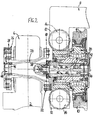
- den Bereich II aus Fig. 1 in einer vergrößerten, detaillierteren Schnittansicht.
- Fig. 1
- a highly schematic plan view of a Doppelachsfahrwerks with two invention, here driven Losradachsen and
- Fig. 2
- the area II of Fig. 1 in an enlarged, more detailed sectional view.
In Fig. 1 ist zunächst beispielhaft eine Anwendung von zwei
erf indungsgemäßen Losradachsen 1 in einem angetriebenen
Doppelachsfahrwerk veranschaulicht. Auf jeder Fahrwerkslängsseite
ist dabei eine Antriebseinheit 2 verhanden, die
aus einem Elektromotor 4 und beidseitig angeflanschten
Kegelrad-Getrieben 6 besteht. Jede Achse weist einen U-förmigen
Radtragrahmen 8 auf, der auch unter dem Begriff
Portalachse bekannt ist. An dem Radtragrahmen 8 sind Räder
10 einzeln gelagert, wobei der Radtragrahmen 8 die Räder
mit seitlichen Tragschenkeln 12 außen umgreift und jedes
Rad 10 auf der Innenseite des zugehörigen Tragschenkels 12
drehbar angelenkt ist. Jede Antriebseinheit 2 ist an einem
nicht dargestellten Fahrwerksrahmen aufgehängt, der sich
über eine Primärfederung auf dem jeweiligen Radtragrahmen
8 abstützt. Dazu weist der Radtragrahmen 8 insbesondere im
Bereich der Tragschenkel 12 Auflageflächen 14 für Primärfederelemente
auf. In Fig. 1 is initially an example of an application of two
erf indungsgemäßen Losradachsen 1 in a driven
Double axle landing gear illustrated. On each chassis side
is a
Wie sich nun aus Fig. 2 ergibt, ist jedes Rad 10 auf seiner
Innenseite drehmomentschlüssig mit einer Welle 16 verbunden,
die sich durch Öffnungen des Rades 10 und des
Tragschenkels 12 nach außen erstreckt. Diese Welle 16 endet
erfindungsgemäß in einer direkt auf der Außenseite des
Tragschenkels 12 gebildeten Kupplungsebene 18.As can be seen from Fig. 2, each
Vorzugsweise ist die Welle 16 auf ihrer Innenseite über ein
lösbares Anschlußelement 30 starr mit dem Rad 10 verbunden,
so daß die Welle koaxial mit dem Rad rotiert. Das Rad 10
selbst ist über eine Radlagerung 32 auf einem in das Rad 10
eingreifenden Achsstummel 34 des Tragschenkels 12 gelagert.
Diese Ausgestaltung gewährleistet eine optimale Lagerbeanspruchung
und dadurch eine lange Haltbarkeit der Lager. Die
Welle 16 kann - wie dargestellt - zusätzlich über ein Drehlager
36 in dem Tragschenkel 12 gelagert sein.Preferably, the
Bei dem dargestellten Anwendungsbeispiel einer angetriebenen
Losradachse 1 bildet die Welle 16 eine Antriebs-Zwischenwelle
20, die in der Kupplungsebene 18 über eine
Kupplung 22 mit einer eigentlichen Antriebswelle 24 der
Antriebseinheit 2 verbunden ist. Die Antriebswelle 24 ist
auf ihrer anderen, gegenüberliegenden Seite über eine
weitere Kupplung 26 mit dem Getriebe 6 des Antriebs 2
verbunden. In der bevorzugten Ausgestaltung sind die
Antriebswelle 24 als eine in Verlängerung der Zwischenwelle
im wesentlichen koaxiale, vorzugsweise hohle Kardanwelle
und die zwei beidseitigen Kupplungen 22 und 26 als kardanische
Doppelkupplung ausgeführt. Dabei verläuft die Antriebswelle
24 durch das Getriebe 6 hindurch, so daß eine
antriebsseitige Kupplungsebene 28 auf der vom Tragrahmen 8
wegweisenden Außenseite des Getriebes 6 bzw. des Antriebs
2 liegt, während die abtriebsseitige Kupplungsebene 18 und
die Kupplung 22 zwischen dem Getriebe 6 und dem Tragschenkel
12 des Tragrahmens 8 liegen (vgl. hierzu auch Fig. 1).In the illustrated application example of a driven
Jede Kupplung 22, 26 besteht in an sich bekannter Weise aus
sternförmigen Kupplungsstücken, die unter Zwischenlage von
elastischen, keilartigen Ausgleichselementen ineinandergreifen.
Hierdurch gestatten sie einen kardanischen Ausgleich
von Federungsbewegungen in der Größenordnung von
mindestens ca. ± 15 mm.Each
In weiterer vorteilhafter Ausgestaltung der Erfindung ist
eine Erdungskontaktanordnung 38 an der Welle 16 auf der
Seite der Kupplungsebene 18 integriert angeordnet. Dabei
handelt es sich um eine Schleifkontaktanordnung, um eine
elektrisch leitende Verbindung zwischen rotierenden und
nicht rotierenden Teilen zu gewährleisten. Die Erdungskontaktanordnung
38 ist über eine zentrische, durch die hohl
ausgebildete Welle 16 zur Rad-Innenseite verlaufende
Haltestange 40 und eine sich daran anschließende, horizontale
Drehmomentstütze 42 ortsfest an dem Tragrahmen 8
abgestützt. Dabei kann zwischen der hohlen Welle 16 und der
Haltestange 40 wenigstens ein Drehlager 44 angeordnet sein,
und zwar insbesondere im inneren, etwa in der Ebene des
Rades 10 liegenden Bereich. Bei dieser bevorzugten Anordnung
der Erdungskontaktanordnung 38 ist es zudem vorteilhaft,
wenn die hohle Antriebswelle 24 auf ihrer von der
Zwischenwelle 20 wegweisenden Außenseite eine - vorzugsweise
mit einem lösbaren Deckelelement 46 verschließbare -
Revisionsöffnung 48 für die in die Zwischenwelle 20 integrierte
Erdungskontaktanordnung 38 aufweist.In a further advantageous embodiment of the invention
a
In Abweichung von der dargestellten Ausführungs- und
Anwendungsform kann die erfindungsgemäße Losradachse 1 auch
in einer nicht-angetriebenen Version eingesetzt werden. Es
entfallen dann die Antriebseinheiten 2 mit den Elektromotoren
4 und den Getrieben 6 einschließlich der Antriebswellen
24. Dabei kann dann jede Welle 16 vorteilhafterweise als
Bremswelle genutzt werden, indem sie in der Kupplungsebene
18 mit einer Bremseinrichtung verbunden wird. Bei dieser
nicht dargestellten Alternative ist dann die Bremseinrichtung
bevorzugt als Scheibenbremse ausgeführt, wobei mit der
Welle 16 eine Bremsscheibe verbunden ist, so daß diese
gemeinsam mit dem Rad 10 rotiert. Die Bremsscheibe wirkt
mit einem am Tragschenkel 12 des Radtragrahmens 8 abgestützten
Bremssattel zusammen.Notwithstanding the illustrated embodiment and
Application form, the
Abschließend sollen nochmals die Vorteile der Erfindung wie
folgt zusammengefaßt werden:
Die Erfindung ist nicht auf die dargestellten und beschriebenen Ausführungsbeispiele beschränkt, sondern wird von den folgenden Ansprüchen definiert.The invention is not limited to the illustrated and described Embodiments limited, but is from as defined in the following claims.
Claims (9)
- Loose-wheel axle (1) having individually mounted wheels (10), for single-axle and twin-axle sets of running gear of rail-borne vehicles and particularly low-floored vehicles, having a wheel-carrying frame (8) of which lateral carrier arms (12) fit round the outsides of the wheels (10), each wheel (10) being rotatably mounted, on the inner side of the associated carrier arm (12), on a stub-axle (34) belonging to the carrier arm (12) via a wheel bearing (32) arranged inside the wheel (10), and each wheel (10) being connected on its inner side, in such a way as to be solid under torque, to a shaft (16) which extends outwards through openings in the wheel (10) and the carrier arm (12), characterised in that the shaft (16) terminates at a coupling plane (18) formed directly on the outer side of the carrier arm (12).
- Loose-wheel axle according to claim 1, characterised in that the shaft (16) is rigidly connected to the wheel (10) via a connecting member (30) and is preferably also mounted in the carrier arm (12) via a rotary bearing (36).
- Loose-wheel axle according to claim 1 or 2, characterised in that the shaft (16) has, on the side on which the coupling plane (18) is situated, an integrated earthing contact arrangement (38).
- Loose-wheel axle according to claim 3, characterised in that the earthing contact arrangement (38) is supported in a fixed position via a concentric holding rod (40) which extends through the shaft (16) of hollow form to the inner side of the wheel and via a torque reaction strut (42).
- Loose-wheel axle according to claim 4, characterised in that at least one rotary bearing (44) is arranged between the hollow shaft (16) and the retaining rod (40).
- Loose-wheel axle according to one of claims 1 to 5, characterised in that the shaft (16) forms an intermediate drive shaft (20) and is connected, in the coupling plane (18), via a coupling (22), to a drive shaft (24) belonging to a drive (2) which is arranged on the outside on the longitudinal side of the set of running gear.
- Loose-wheel axle according to claim 6, characterised in that the drive shaft (24), of hollow form, has an inspection opening (48) for the earthing contact arrangement (38) on its outer side directed away from the intermediate shaft (20).
- Loose-wheel axle according to one of claims 1 to 5, characterised in that the shaft (16) forms a braking shaft and is connected in the coupling plane (18) to a braking means
- Loose-wheel axle according to claim 8, characterised in that the braking means is in the form of a disc brake, in which case a brake disc, which co-operates with a brake calliper supported on the carrier arm (12), is connected to the braking shaft.
Applications Claiming Priority (2)
| Application Number | Priority Date | Filing Date | Title |
|---|---|---|---|
| DE19930424 | 1999-07-01 | ||
| DE19930424A DE19930424A1 (en) | 1999-07-01 | 1999-07-01 | Idler wheel axle for rail vehicles |
Publications (2)
| Publication Number | Publication Date |
|---|---|
| EP1065122A1 EP1065122A1 (en) | 2001-01-03 |
| EP1065122B1 true EP1065122B1 (en) | 2004-02-18 |
Family
ID=7913345
Family Applications (1)
| Application Number | Title | Priority Date | Filing Date |
|---|---|---|---|
| EP00111850A Expired - Lifetime EP1065122B1 (en) | 1999-07-01 | 2000-06-08 | Idler wheel axle for railway vehicles |
Country Status (4)
| Country | Link |
|---|---|
| EP (1) | EP1065122B1 (en) |
| AT (1) | ATE259729T1 (en) |
| DE (2) | DE19930424A1 (en) |
| ES (1) | ES2213518T3 (en) |
Cited By (2)
| Publication number | Priority date | Publication date | Assignee | Title |
|---|---|---|---|---|
| WO2020187520A1 (en) | 2019-03-19 | 2020-09-24 | Bombardier Transportation Gmbh | Wheel arrangement for a rail vehicle |
| EP3971051A1 (en) | 2020-09-16 | 2022-03-23 | Bombardier Transportation GmbH | Wheel arrangement for a rail vehicle |
Families Citing this family (4)
| Publication number | Priority date | Publication date | Assignee | Title |
|---|---|---|---|---|
| DE10122185A1 (en) * | 2001-05-08 | 2002-11-14 | Gutehoffnungshuette Radsatz | Loose wheel assembly for rail vehicles has support element to accommodate stationary components of three functional units, while wheel provides mountings for associated rotating components |
| DE102015222125A1 (en) * | 2015-11-10 | 2017-05-11 | Bombardier Transportation Gmbh | Drive arrangement for a rail vehicle, rail vehicle with the drive assembly and method for manufacturing |
| CN105460023B (en) * | 2015-12-25 | 2017-12-12 | 中车戚墅堰机车车辆工艺研究所有限公司 | Low-floor rail vehicle gear-box |
| IT201600088005A1 (en) | 2016-08-30 | 2018-03-02 | Lucchini Rs Spa | AXLE-AXLE OF RAILWAY AND RAILWAY VEHICLES WITH REDUCED FLOOR |
Family Cites Families (6)
| Publication number | Priority date | Publication date | Assignee | Title |
|---|---|---|---|---|
| DE3230453A1 (en) * | 1982-08-16 | 1984-02-16 | Kollektra Metall- und Kunststoff-Werk GmbH, 6301 Wettenberg | Contact arrangement for electrically bridging the axle bearings of rail vehicles |
| DE3931912A1 (en) * | 1989-09-25 | 1991-04-04 | Eickhoff Geb | Individual drive for tram car wheel - has wheel mounted on shaft formed integrally with internal wall of gear box |
| DK0567445T3 (en) * | 1992-04-22 | 1996-05-20 | Sgp Verkehrstechnik | Single-wheel bogie for a rail vehicle, especially for low-floor carts |
| DE4429889A1 (en) | 1994-08-24 | 1996-02-29 | Bergische Stahlindustrie | Powered undercarriage for rail vehicles |
| DE4445407C1 (en) * | 1994-12-20 | 1996-02-22 | Siemens Ag | Single-wheel drive for electric rail vehicle |
| DE19650913A1 (en) | 1996-12-07 | 1998-06-10 | Sab Wabco Bsi Verkehrstechnik | Driven idler axle |
-
1999
- 1999-07-01 DE DE19930424A patent/DE19930424A1/en not_active Withdrawn
-
2000
- 2000-06-08 DE DE50005301T patent/DE50005301D1/en not_active Expired - Lifetime
- 2000-06-08 AT AT00111850T patent/ATE259729T1/en active
- 2000-06-08 EP EP00111850A patent/EP1065122B1/en not_active Expired - Lifetime
- 2000-06-08 ES ES00111850T patent/ES2213518T3/en not_active Expired - Lifetime
Cited By (2)
| Publication number | Priority date | Publication date | Assignee | Title |
|---|---|---|---|---|
| WO2020187520A1 (en) | 2019-03-19 | 2020-09-24 | Bombardier Transportation Gmbh | Wheel arrangement for a rail vehicle |
| EP3971051A1 (en) | 2020-09-16 | 2022-03-23 | Bombardier Transportation GmbH | Wheel arrangement for a rail vehicle |
Also Published As
| Publication number | Publication date |
|---|---|
| ES2213518T3 (en) | 2004-09-01 |
| ATE259729T1 (en) | 2004-03-15 |
| EP1065122A1 (en) | 2001-01-03 |
| DE50005301D1 (en) | 2004-03-25 |
| DE19930424A1 (en) | 2001-01-04 |
Similar Documents
| Publication | Publication Date | Title |
|---|---|---|
| DE60216855T2 (en) | Drive bogie for a low-floor rail vehicle | |
| EP0698540B1 (en) | Driven running gear for railway vehicles | |
| EP0883540B1 (en) | Railway bogie with a driven wheel axle | |
| DE4106070C2 (en) | ||
| AT408333B (en) | VEHICLE WHEEL | |
| EP1685014B1 (en) | Driven chassis for rail vehicles in particular bogies for low-floor vehicles | |
| EP1065122B1 (en) | Idler wheel axle for railway vehicles | |
| EP2762215B1 (en) | Vehicle model | |
| EP2692607B1 (en) | Suspension system for a railway vehicle with releasable rigid connection between the wheels | |
| WO2009144319A1 (en) | Bogie with divided frame and motor-transmission coupling unit | |
| DE102008027129A1 (en) | Bogie with two-part frame | |
| WO2017081032A1 (en) | Drive arrangement for a rail vehicle, rail vehicle having the drive arrangement and manufacturing method | |
| EP1532033B1 (en) | Driven bogie for a rail vehicle | |
| AT519147B1 (en) | Wheel arrangement for a rail vehicle | |
| AT406569B (en) | CHASSIS FOR A RAIL VEHICLE, IN PARTICULAR LOW-FLOOR TRAM | |
| EP0439573B1 (en) | Bogie for an underslung vehicle | |
| EP1149009B1 (en) | Idler wheel axle for rail vehicles | |
| DE102017102138A1 (en) | System for connecting a gearbox with a wheel set shaft and arrangement for a bogie for rail vehicles | |
| EP0838386A1 (en) | Railway vehicle with at least one running gear and running gear for such a vehicle | |
| EP0878368B1 (en) | Drive unit for railway vehicles | |
| DE2943014A1 (en) | RAIL VEHICLE CHASSIS | |
| EP2939898B1 (en) | Bogie for railway vehicles with three wheel sets | |
| CH631664A5 (en) | Rail vehicle with bogies having at least two wheel sets | |
| AT526054B1 (en) | Chassis for a rail vehicle and rail vehicle | |
| WO2017093094A1 (en) | Chassis frame for a rail vehicle |
Legal Events
| Date | Code | Title | Description |
|---|---|---|---|
| PUAI | Public reference made under article 153(3) epc to a published international application that has entered the european phase |
Free format text: ORIGINAL CODE: 0009012 |
|
| AK | Designated contracting states |
Kind code of ref document: A1 Designated state(s): AT BE CH CY DE DK ES FI FR GB GR IE IT LI LU MC NL PT SE |
|
| AX | Request for extension of the european patent |
Free format text: AL;LT;LV;MK;RO;SI |
|
| 17P | Request for examination filed |
Effective date: 20010613 |
|
| AKX | Designation fees paid |
Free format text: AT BE CH CY DE DK ES FI FR GB GR IE IT LI LU MC NL PT SE |
|
| GRAP | Despatch of communication of intention to grant a patent |
Free format text: ORIGINAL CODE: EPIDOSNIGR1 |
|
| GRAS | Grant fee paid |
Free format text: ORIGINAL CODE: EPIDOSNIGR3 |
|
| GRAA | (expected) grant |
Free format text: ORIGINAL CODE: 0009210 |
|
| AK | Designated contracting states |
Kind code of ref document: B1 Designated state(s): AT BE CH CY DE DK ES FI FR GB GR IE IT LI LU MC NL PT SE |
|
| PG25 | Lapsed in a contracting state [announced via postgrant information from national office to epo] |
Ref country code: FI Free format text: LAPSE BECAUSE OF FAILURE TO SUBMIT A TRANSLATION OF THE DESCRIPTION OR TO PAY THE FEE WITHIN THE PRESCRIBED TIME-LIMIT Effective date: 20040218 Ref country code: CY Free format text: LAPSE BECAUSE OF FAILURE TO SUBMIT A TRANSLATION OF THE DESCRIPTION OR TO PAY THE FEE WITHIN THE PRESCRIBED TIME-LIMIT Effective date: 20040218 Ref country code: IE Free format text: LAPSE BECAUSE OF FAILURE TO SUBMIT A TRANSLATION OF THE DESCRIPTION OR TO PAY THE FEE WITHIN THE PRESCRIBED TIME-LIMIT Effective date: 20040218 |
|
| REG | Reference to a national code |
Ref country code: GB Ref legal event code: FG4D Free format text: NOT ENGLISH |
|
| REG | Reference to a national code |
Ref country code: SE Ref legal event code: TRGR |
|
| REG | Reference to a national code |
Ref country code: CH Ref legal event code: EP Ref country code: CH Ref legal event code: NV Representative=s name: BRAUN & PARTNER PATENT-, MARKEN-, RECHTSANWAELTE |
|
| REG | Reference to a national code |
Ref country code: IE Ref legal event code: FG4D Free format text: GERMAN |
|
| REF | Corresponds to: |
Ref document number: 50005301 Country of ref document: DE Date of ref document: 20040325 Kind code of ref document: P |
|
| GBT | Gb: translation of ep patent filed (gb section 77(6)(a)/1977) |
Effective date: 20040310 |
|
| PG25 | Lapsed in a contracting state [announced via postgrant information from national office to epo] |
Ref country code: DK Free format text: LAPSE BECAUSE OF FAILURE TO SUBMIT A TRANSLATION OF THE DESCRIPTION OR TO PAY THE FEE WITHIN THE PRESCRIBED TIME-LIMIT Effective date: 20040518 Ref country code: GR Free format text: LAPSE BECAUSE OF FAILURE TO SUBMIT A TRANSLATION OF THE DESCRIPTION OR TO PAY THE FEE WITHIN THE PRESCRIBED TIME-LIMIT Effective date: 20040518 |
|
| PG25 | Lapsed in a contracting state [announced via postgrant information from national office to epo] |
Ref country code: LU Free format text: LAPSE BECAUSE OF NON-PAYMENT OF DUE FEES Effective date: 20040608 |
|
| PG25 | Lapsed in a contracting state [announced via postgrant information from national office to epo] |
Ref country code: ES Free format text: LAPSE BECAUSE OF NON-PAYMENT OF DUE FEES Effective date: 20040609 Ref country code: SE Free format text: LAPSE BECAUSE OF NON-PAYMENT OF DUE FEES Effective date: 20040609 |
|
| PG25 | Lapsed in a contracting state [announced via postgrant information from national office to epo] |
Ref country code: MC Free format text: LAPSE BECAUSE OF NON-PAYMENT OF DUE FEES Effective date: 20040630 Ref country code: BE Free format text: LAPSE BECAUSE OF NON-PAYMENT OF DUE FEES Effective date: 20040630 |
|
| REG | Reference to a national code |
Ref country code: ES Ref legal event code: FG2A Ref document number: 2213518 Country of ref document: ES Kind code of ref document: T3 |
|
| REG | Reference to a national code |
Ref country code: IE Ref legal event code: FD4D |
|
| ET | Fr: translation filed | ||
| PLBE | No opposition filed within time limit |
Free format text: ORIGINAL CODE: 0009261 |
|
| STAA | Information on the status of an ep patent application or granted ep patent |
Free format text: STATUS: NO OPPOSITION FILED WITHIN TIME LIMIT |
|
| BERE | Be: lapsed |
Owner name: GUTEHOFFNUNGSHUTTE *RADSATZ G.M.B.H. Effective date: 20040630 |
|
| PG25 | Lapsed in a contracting state [announced via postgrant information from national office to epo] |
Ref country code: NL Free format text: LAPSE BECAUSE OF NON-PAYMENT OF DUE FEES Effective date: 20050101 |
|
| EUG | Se: european patent has lapsed | ||
| EUG | Se: european patent has lapsed | ||
| 26N | No opposition filed |
Effective date: 20041119 |
|
| NLV4 | Nl: lapsed or anulled due to non-payment of the annual fee |
Effective date: 20050101 |
|
| REG | Reference to a national code |
Ref country code: ES Ref legal event code: FD2A Effective date: 20040609 |
|
| PG25 | Lapsed in a contracting state [announced via postgrant information from national office to epo] |
Ref country code: PT Free format text: LAPSE BECAUSE OF NON-PAYMENT OF DUE FEES Effective date: 20040718 |
|
| REG | Reference to a national code |
Ref country code: FR Ref legal event code: PLFP Year of fee payment: 17 |
|
| REG | Reference to a national code |
Ref country code: FR Ref legal event code: PLFP Year of fee payment: 18 |
|
| REG | Reference to a national code |
Ref country code: CH Ref legal event code: PCAR Free format text: NEW ADDRESS: HOLEESTRASSE 87, 4054 BASEL (CH) |
|
| REG | Reference to a national code |
Ref country code: FR Ref legal event code: PLFP Year of fee payment: 19 |
|
| PGFP | Annual fee paid to national office [announced via postgrant information from national office to epo] |
Ref country code: IT Payment date: 20190624 Year of fee payment: 20 Ref country code: DE Payment date: 20190619 Year of fee payment: 20 |
|
| PGFP | Annual fee paid to national office [announced via postgrant information from national office to epo] |
Ref country code: FR Payment date: 20190619 Year of fee payment: 20 |
|
| PGFP | Annual fee paid to national office [announced via postgrant information from national office to epo] |
Ref country code: CH Payment date: 20190619 Year of fee payment: 20 |
|
| PGFP | Annual fee paid to national office [announced via postgrant information from national office to epo] |
Ref country code: AT Payment date: 20190621 Year of fee payment: 20 Ref country code: GB Payment date: 20190619 Year of fee payment: 20 |
|
| REG | Reference to a national code |
Ref country code: DE Ref legal event code: R071 Ref document number: 50005301 Country of ref document: DE |
|
| REG | Reference to a national code |
Ref country code: CH Ref legal event code: PL |
|
| REG | Reference to a national code |
Ref country code: GB Ref legal event code: PE20 Expiry date: 20200607 |
|
| REG | Reference to a national code |
Ref country code: AT Ref legal event code: MK07 Ref document number: 259729 Country of ref document: AT Kind code of ref document: T Effective date: 20200608 |
|
| PG25 | Lapsed in a contracting state [announced via postgrant information from national office to epo] |
Ref country code: GB Free format text: LAPSE BECAUSE OF EXPIRATION OF PROTECTION Effective date: 20200607 |