EP1247713B1 - Driven running gear without wheelsets for railway vehicles - Google Patents
Driven running gear without wheelsets for railway vehicles Download PDFInfo
- Publication number
- EP1247713B1 EP1247713B1 EP02006809A EP02006809A EP1247713B1 EP 1247713 B1 EP1247713 B1 EP 1247713B1 EP 02006809 A EP02006809 A EP 02006809A EP 02006809 A EP02006809 A EP 02006809A EP 1247713 B1 EP1247713 B1 EP 1247713B1
- Authority
- EP
- European Patent Office
- Prior art keywords
- individual wheels
- motor
- wheels
- synchronous motors
- motors
- Prior art date
- Legal status (The legal status is an assumption and is not a legal conclusion. Google has not performed a legal analysis and makes no representation as to the accuracy of the status listed.)
- Expired - Fee Related
Links
Images

Classifications
-
- B—PERFORMING OPERATIONS; TRANSPORTING
- B61—RAILWAYS
- B61F—RAIL VEHICLE SUSPENSIONS, e.g. UNDERFRAMES, BOGIES OR ARRANGEMENTS OF WHEEL AXLES; RAIL VEHICLES FOR USE ON TRACKS OF DIFFERENT WIDTH; PREVENTING DERAILING OF RAIL VEHICLES; WHEEL GUARDS, OBSTRUCTION REMOVERS OR THE LIKE FOR RAIL VEHICLES
- B61F3/00—Types of bogies
- B61F3/16—Types of bogies with a separate axle for each wheel
-
- B—PERFORMING OPERATIONS; TRANSPORTING
- B61—RAILWAYS
- B61C—LOCOMOTIVES; MOTOR RAILCARS
- B61C9/00—Locomotives or motor railcars characterised by the type of transmission system used; Transmission systems specially adapted for locomotives or motor railcars
- B61C9/38—Transmission systems in or for locomotives or motor railcars with electric motor propulsion
- B61C9/52—Transmission systems in or for locomotives or motor railcars with electric motor propulsion with transmission shafts at an angle to the driving axles
-
- B—PERFORMING OPERATIONS; TRANSPORTING
- B61—RAILWAYS
- B61F—RAIL VEHICLE SUSPENSIONS, e.g. UNDERFRAMES, BOGIES OR ARRANGEMENTS OF WHEEL AXLES; RAIL VEHICLES FOR USE ON TRACKS OF DIFFERENT WIDTH; PREVENTING DERAILING OF RAIL VEHICLES; WHEEL GUARDS, OBSTRUCTION REMOVERS OR THE LIKE FOR RAIL VEHICLES
- B61F3/00—Types of bogies
- B61F3/02—Types of bogies with more than one axle
- B61F3/04—Types of bogies with more than one axle with driven axles or wheels
Definitions
- the invention relates to a powered chassis for rail vehicles without wheelsets.
- a single wheel drive for an electric vehicle in which a motor with its stator is attached to a first chassis and in which the first chassis part is supported via a primary suspension in an unsprung second chassis part on which the single wheel is rotatably supported known.
- the rotor of the motor transmits its torque via a coupling device whose radial mobility is greater than the travel of the primary suspension.
- a mechanical coupling lateral pairs of wheels is known from DE 44 46 043 C1, in which a chassis with two parallel side members, which are interconnected by at least one cross member, and two pairs of wheels each consisting of two individual wheels, wherein at least two axially opposed single wheels of one Motor are driven with gear and each single wheel is rotatably mounted in a wheel rail, wherein the wheel rails are arranged parallel to the chassis longitudinal axis at both ends of parallel chassis parts and vertically deflectable about a joint, and the motors with their longitudinal axes parallel to the longitudinal beams, respectively and the wheel rails are formed as a transmission housing.
- Such arrangements have also become known through WO 93/22152.
- the individual wheels or the Einzelradcrue are driven by a respective Asynchronfahrmotor, which are electrically connected in parallel to a common pulse inverter. As a result, they are coupled via an electric slip clutch and not coupled speed-locked.
- the disadvantage here is that the self-stable tracking of the wheelset, i. of the sine wave, is lost, resulting in increased wear on wheels and rails.
- the known solution leads to poor directional stability in rail vehicles without wheelsets.
- the invention has the object to provide a chassis of a rail vehicle, which avoids the above-mentioned disadvantages and enables an economical drive concept of such a chassis.
- a coupling of the two individually driven single wheels or Einzelradcrue is created by an electromagnetic torsion spring by the execution.
- the electromagnetic wheelset also works in case of failure or shutdown of a permanent magnet synchronous motors feeding converter, in particular pulse inverter and in pure rolling of the vehicle by permanent excitation of the synchronous motors.
- a permanent magnet synchronous motors feeding converter in particular pulse inverter
- pure rolling of the vehicle by permanent excitation of the synchronous motors.
- permanent-magnet synchronous motors By using permanent-magnet synchronous motors, the drive efficiency increases, and also electrical noise and pendulum moments of the traction motors are reduced compared to asynchronous motors.
- the synchronous motors drive the single wheels either directly or are mechanically coupled via gears with the single wheels or Einzelradpresen.
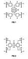
- the 1 shows the basic drive of a chassis with its individual wheels 1.
- the single wheels 1 are driven by coupling means 2 by a synchronous motor 3, preferably a permanent magnet synchronous motor.
- the electrical supply of the synchronous motors 3 of axially adjacent individual wheels 1 takes place in each case via a pulse inverter 4.
- the synchronous motors 3 can be located on the cross members of the chassis or on longitudinal members, not shown.
- two individual wheels 1, which are located behind one another in the direction of travel, are each assigned to a synchronous motor 3, which directly drives these individual wheels via a mechanical coupling device 2.
- FIG 3 shows by way of example a further embodiment of FIG 2 in which the drive of the individual wheels 1 is not directly, but via a gear 5.
- coupling means 2 angular and axial compliant couplings are provided in the described embodiments, e.g. Lugs, curved tooth or wedge pack couplings.
- angular and axial compliant couplings radially and axially compliant couplings, e.g. Parallel crank and Drewirlenkerkuppl12. be used.
- FIG 4 shows an embodiment in which one behind the other single wheels 1 are mechanically rigidly coupled.
- This coupling device 2 can also take place via a gear 5.
- a coupling device 2 the embodiments described in FIG 3 are also suitable.
- the two synchronous motors 3 of a chassis are electrically connected in parallel and are fed by a common pulse inverter.
- the synchronous drives are provided as internal rotor motors or as external rotor motors.
- the electromagnetic wheel set shaft formed according to the invention also functions in the event of failure or disconnection of the pulse inverter and pure coasting of the vehicle due to the permanent excitation of the synchronous motors 3.
- the electromagnetic wheelset shaft furthermore requires no software or commissioning effort. It reduces the wear on wheels and rails, leads to increased ride comfort, and reduced by the electrical parallel connection of the traction motors, in particular permanent-magnet synchronous motors 3, the number of required power inverters.
Abstract
Description
Die Erfindung betrifft ein angetriebenes Fahrwerk für Schienenfahrzeuge ohne Radsätze.The invention relates to a powered chassis for rail vehicles without wheelsets.
Bei Schienenfahrzeugen wird in der Regel ein gesamter Radsatz durch einen Motor angetrieben. Die Niederflurigkeit, insbesondere moderner Straßenbahnen erzwingt die Auflösung des Radsatzes und führt zu Einzelrädern oder über je einen Längsmotor mechanisch gekoppelten seitlichen Radpaaren.In rail vehicles, an entire wheelset is usually driven by a motor. The low-floor, especially modern trams enforces the resolution of the wheelset and leads to single wheels or via a longitudinal motor mechanically coupled side pairs of wheels.
So ist ein einzelner Radantrieb für ein elektrisches Fahrzeug bei dem ein Motor mit seinem Stator an einem ersten Fahrwerk befestigt ist und bei dem sich das erste Fahrwerksteil über eine Primärfederung in einen ungefederten zweiten Fahrwerksteil abstützt auf dem das Einzelrad drehbar gelagert ist, bekannt. Dabei überträgt der Rotor des Motors sein Drehmoment über eine Kupplungseinrichtung deren radiale Beweglichkeit größer ist als der Federweg der Primärfederung. Dieser Einzelradantrieb, der insbesondere für elektrisch angetriebene Schienenfahrzeuge geeignet ist, hat den Vorteil, dass der Anteil an ungefederten Massen gering ist.Thus, a single wheel drive for an electric vehicle in which a motor with its stator is attached to a first chassis and in which the first chassis part is supported via a primary suspension in an unsprung second chassis part on which the single wheel is rotatably supported known. In this case, the rotor of the motor transmits its torque via a coupling device whose radial mobility is greater than the travel of the primary suspension. This single-wheel drive, which is particularly suitable for electrically powered rail vehicles, has the advantage that the proportion of unsprung masses is low.
Eine mechanische Kopplung seitlicher Radpaare ist aus der DE 44 46 043 C1 bekannt, bei der ein Fahrwerk mit zwei parallelen Längsträgern, die durch wenigstens einen Querträger miteinander verbunden sind, und zwei Radpaaren aus jeweils zwei Einzelrädern, wobei wenigstens zwei axial gegenüberliegende Einzelräder von jeweils einem Motor mit Getriebe angetrieben sind und jedes Einzelrad in einer Radschiene drehbar gelagert ist, wobei die Radschienen jeweils parallel zur Fahrwerkslängsachse an beiden Enden von parallelen Fahrwerksteilen angeordnet und um ein Gelenk vertikal auslenkbar sind, und die Motoren mit ihren Längsachsen parallel zu den Längsträgern,angeordnet und die Radschienen als Getriebegehäuse ausgebildet sind. Derartige Anordnungen sind ebenso durch die WO 93/22152 bekannt geworden.A mechanical coupling lateral pairs of wheels is known from DE 44 46 043 C1, in which a chassis with two parallel side members, which are interconnected by at least one cross member, and two pairs of wheels each consisting of two individual wheels, wherein at least two axially opposed single wheels of one Motor are driven with gear and each single wheel is rotatably mounted in a wheel rail, wherein the wheel rails are arranged parallel to the chassis longitudinal axis at both ends of parallel chassis parts and vertically deflectable about a joint, and the motors with their longitudinal axes parallel to the longitudinal beams, respectively and the wheel rails are formed as a transmission housing. Such arrangements have also become known through WO 93/22152.
Bei diesem Stand der Technik werden die Einzelräder oder die Einzelradpaare von je einem Asynchronfahrmotor angetrieben, die an einem gemeinsamen Pulswechselrichter elektrisch parallelgeschaltet sind. Dadurch sind sie über eine elektrische Schlupfkupplung gekoppelt und nicht drehzahlstarr gekoppelt. Nachteilig dabei ist, dass durch die Elimination der Radsatzwelle die eigenstabile Spurführung des Radsatzes, d.h. des Sinuswellenlaufes, verloren geht, was zu erhöhtem Verschleiß an Rädern und Schienen führt. Außerdem führt die bekannte Lösung zu einem schlechten Geradeauslauf bei Schienenfahrzeugen ohne Radsätze.In this prior art, the individual wheels or the Einzelradpaare are driven by a respective Asynchronfahrmotor, which are electrically connected in parallel to a common pulse inverter. As a result, they are coupled via an electric slip clutch and not coupled speed-locked. The disadvantage here is that the self-stable tracking of the wheelset, i. of the sine wave, is lost, resulting in increased wear on wheels and rails. In addition, the known solution leads to poor directional stability in rail vehicles without wheelsets.
Ausgehend davon, liegt der Erfindung die Aufgabe zugrunde, ein Fahrwerk eines Schienenfahrzeugs zu schaffen, das die oben genannten Nachteile vermeidet und ein wirtschaftliches Antriebskonzept eines derartigen Fahrwerks ermöglicht.Proceeding from this, the invention has the object to provide a chassis of a rail vehicle, which avoids the above-mentioned disadvantages and enables an economical drive concept of such a chassis.
Die Lösung der gestellten Aufgabe gelingt durch ein Triebfahrwerk nach Anspruch 1 oder Anspruch 4.The solution of the problem is achieved by a traction drive according to claim 1 or claim 4.
Erfindungsgemäß ist durch die Ausführung eine Kopplung der beiden einzeln angetriebenen Einzelräder oder Einzelradpaare über eine elektromagnetische Drehfeder geschaffen. Dies führt zu einem deutlich verbesserten Geradeauslauf der Schienenfahrzeuge gegenüber Schienenfahrzeugen mit Asynchronfahrmotoren ohne Radsätze. Damit wird der Verschleiß an Rädern und Schienen reduziert. Dies führt u.a. zu einem erhöhten Fahrkomfort der Fahrgäste.According to the invention a coupling of the two individually driven single wheels or Einzelradpaare is created by an electromagnetic torsion spring by the execution. This leads to a significantly improved straight-line stability of rail vehicles compared to rail vehicles with asynchronous motors without wheelsets. This reduces the wear on wheels and rails. This leads u.a. to an increased driving comfort of the passengers.
Es ist somit eine elektromagnetische Radsatzwelle geschaffen, die wie eine mechanische Radsatzwelle keinerlei zusätzlichen Software- oder Inbetriebnahmeaufwand erfordert. Die elektromagnetische Radsatzwelle funktioniert auch bei Ausfall oder Abschalten eines die permanentmagneterregten Synchronmotoren speisenden Umrichters, insbesondere Pulswechselrichters und bei reinem Rollen des Fahrzeugs durch permanente Erregung der Synchronmotoren. Durch Verwendung permanenterregter Synchronmotoren erhöht sich der Antriebswirkungsgrad, und außerdem werden elektrische Geräusche und Pendelmomente der Fahrmotoren gegenüber Asynchronmotoren verringert.It is thus an electromagnetic axle set created that requires no additional software or commissioning effort like a mechanical axle. The electromagnetic wheelset also works in case of failure or shutdown of a permanent magnet synchronous motors feeding converter, in particular pulse inverter and in pure rolling of the vehicle by permanent excitation of the synchronous motors. By using permanent-magnet synchronous motors, the drive efficiency increases, and also electrical noise and pendulum moments of the traction motors are reduced compared to asynchronous motors.
Die Synchronmotoren treiben die Einzelräder entweder direkt an oder sind über Getriebe mit den Einzelrädern oder Einzelradpaaren mechanisch gekoppelt.The synchronous motors drive the single wheels either directly or are mechanically coupled via gears with the single wheels or Einzelradpaaren.
Die Verwendung eines derartigen Antriebssystems ist insbesondere bei Niederflurstraßenbahnen ohne Radsätze vorteilhaft.The use of such a drive system is particularly advantageous in low-floor trams without wheelsets.
Die Erfindung sowie weitere vorteilhafte Ausgestaltungen der Erfindung gemäß Merkmalen der Unteransprüche werden im folgenden anhand schematisch dargestellter Ausführungsbeispiele in der Zeichnung näher erläutert, darin zeigen:
- FIG 1
- den prinzipiellen Einzelradantrieb eines Fahrwerks,
- FIG 2
- den prinzipiellen Einzelradpaarantrieb eines Fahrwerks,
- FIG 3
- den prinzipiellen Einzelradpaarantrieb mit Getriebe eines Fahrwerks,
- FIG 4
- einen weiteren Einzelradpaarantrieb mit Getriebe.
- FIG. 1
- the principle independent wheel drive of a chassis,
- FIG. 2
- the principle single wheel pair drive of a chassis,
- FIG. 3
- the principle of single-wheel-pair drive with gearbox of a chassis,
- FIG. 4
- another Einzelradpaarantrieb with gear.
FIG 1 zeigt den prinzipiellen Antrieb eines Fahrwerks mit seinen Einzelrädern 1. Die Einzelräder 1 werden über Kupplungseinrichtungen 2 von einem Synchronmotor 3, vorzugsweise einem permanentmagneterregten Synchronmotor, angetrieben. Die elektrische Versorgung der Synchronmotoren 3 von axial nebeneinander liegenden Einzelrädern 1 erfolgt jeweils über einen Pulswechselrichter 4. Dabei können die Synchronmotoren 3 sich an den Querträgern des Fahrwerks oder an nicht näher dargestellten Längsträgern befinden.1 shows the basic drive of a chassis with its individual wheels 1. The single wheels 1 are driven by coupling means 2 by a
In einer weiteren Ausführungsform sind zwei Einzelräder 1, die sich in Fahrtrichtung hintereinander befinden, jeweils einem Synchronmotor 3 zugeordnet, der diese Einzelräder über eine mechanische Kupplungseinrichtung 2 direkt antreibt.In a further embodiment, two individual wheels 1, which are located behind one another in the direction of travel, are each assigned to a
FIG 3 zeigt beispielhaft eine weitere Ausführungsform der FIG 2 bei der der Antrieb der Einzelräder 1 nicht direkt, sondern über ein Getriebe 5 erfolgt. Als Kupplungseinrichtung 2 sind bei den beschriebenen Ausführungsformen winkel- und axialnachgiebige Kupplungen vorgesehen, wie z.B. Laschen, Bogenzahn- oder Keilpaketkupplungen. Anstelle von winkel- und axial nachgiebigen Kupplungen können auch radial- und axial nachgiebigen Kupplungen, z.B. Parallelkurbel- und Dreiringlenkerkupplungen eingesetzt werden.3 shows by way of example a further embodiment of FIG 2 in which the drive of the individual wheels 1 is not directly, but via a
FIG 4 zeigt eine Ausführung, bei der hintereinanderliegende Einzelräder 1 mechanisch starr gekoppelt sind. Diese Kupplungseinrichtung 2 kann auch über ein Getriebe 5 erfolgen. Als Kupplungseinrichtung 2 eignen sich auch die unter FIG 3 beschriebenen Ausführungsformen. Es werden somit zwei Einzelräder 1 über einen Synchronmotor 3 angetrieben. Die beiden Synchronmotoren 3 eines Fahrwerks sind elektrisch parallel geschaltet und werden von einem gemeinsamen Pulswechselrichter gespeist.4 shows an embodiment in which one behind the other single wheels 1 are mechanically rigidly coupled. This
Bei Ausführung der Einzelradantriebe nach FIG 1 sind die Synchronantriebe als Innenläufer- oder auch als Außenläufermotor vorgesehen.In the embodiment of the individual wheel drives according to FIG. 1, the synchronous drives are provided as internal rotor motors or as external rotor motors.
Die erfindungsgemäß gebildete elektromagnetische Radsatzwelle funktioniert auch bei Ausfall oder Abschalten des Pulswechselrichters und reinem Ausrollen des Fahrzeugs aufgrund der Permanenterregung der Synchronmotoren 3. Die elektromagnetische Radsatzwelle erfordert weiterhin keinerlei Software- oder Inbetriebnahmeaufwand. Sie reduziert den Verschleiß an Rädern und Schienen, führt zu einem erhöhten Fahrkomfort, und reduziert durch die elektrische Parallelschaltung der Fahrmotoren, insbesondere permanenterregte Synchronmotoren 3, die Anzahl der erforderlichen Pulwechselrichter.The electromagnetic wheel set shaft formed according to the invention also functions in the event of failure or disconnection of the pulse inverter and pure coasting of the vehicle due to the permanent excitation of the
Claims (6)
- Motor bogie of a rail vehicle having the following features:- individual wheels (1) which are each driven by permanently excited synchronous motors (3),- an electrical coupling of the two opposing individual wheels (1) by parallel connection and by supplying power to both synchronous motors (3) via a common converter, in particular a pulse inverter (4).
- Motor bogie according to claim 1, characterised in that the synchronous motors (3) drive the individual wheels (1) directly.
- Motor bogie according to claim 1, characterised in that the synchronous motors (3) drive the individual wheels (1) via a gear unit (3).
- Motor bogie with individual wheels (1), wherein two individual wheels (1) are in each case mechanically rigidly coupled in series and are driven via a common synchronous motor (3), wherein the two synchronous motors (3) assigned to a bogie are electrically connected in parallel and are supplied with power by a common converter, in particular a pulse inverter (4).
- Motor bogie according to claim 4, characterised in that the mechanically rigidly coupled individual wheels (1) are driven by the synchronous motor (3) via a gear unit (5).
- Use of a motor bogie according to one or more of the preceding claims, in particular in the case of low-floor trams.
Applications Claiming Priority (2)
| Application Number | Priority Date | Filing Date | Title |
|---|---|---|---|
| DE10117031 | 2001-04-05 | ||
| DE10117031A DE10117031A1 (en) | 2001-04-05 | 2001-04-05 | Power train for rail vehicles |
Publications (3)
| Publication Number | Publication Date |
|---|---|
| EP1247713A2 EP1247713A2 (en) | 2002-10-09 |
| EP1247713A3 EP1247713A3 (en) | 2003-04-16 |
| EP1247713B1 true EP1247713B1 (en) | 2006-12-20 |
Family
ID=7680531
Family Applications (1)
| Application Number | Title | Priority Date | Filing Date |
|---|---|---|---|
| EP02006809A Expired - Fee Related EP1247713B1 (en) | 2001-04-05 | 2002-03-25 | Driven running gear without wheelsets for railway vehicles |
Country Status (3)
| Country | Link |
|---|---|
| EP (1) | EP1247713B1 (en) |
| AT (1) | ATE348741T1 (en) |
| DE (2) | DE10117031A1 (en) |
Cited By (2)
| Publication number | Priority date | Publication date | Assignee | Title |
|---|---|---|---|---|
| EP2557014A2 (en) | 2011-08-12 | 2013-02-13 | Traktionssysteme Austria GmbH | Methods for regulating a drive unit for rail vehicles and drive unit for rail vehicles |
| US8978563B2 (en) | 2007-04-05 | 2015-03-17 | Alstom Transport Sa | Motor-driven bogie for a streetcar |
Families Citing this family (9)
| Publication number | Priority date | Publication date | Assignee | Title |
|---|---|---|---|---|
| DE10239853A1 (en) * | 2002-08-29 | 2004-03-18 | Siemens Ag | motor bogie |
| CZ303294B6 (en) * | 2007-05-29 | 2012-07-18 | ŠKODA TRANSPORTATION a.s. | Driving bogie of rail vehicles with direct drive of wheels |
| DE102009042870A1 (en) * | 2009-09-24 | 2011-03-31 | Siemens Aktiengesellschaft | Rail vehicle with single wheel drives |
| DE102013204232B4 (en) * | 2013-03-12 | 2014-11-20 | Siemens Aktiengesellschaft | Asymmetric drive of a rail vehicle with longitudinal gear sets |
| CN103381837A (en) * | 2013-06-28 | 2013-11-06 | 长春轨道客车股份有限公司 | Synchronous driving mechanism with two motors and two wheels for power bogie of 100% low-floor individual wheel |
| EP3016833B1 (en) | 2013-07-05 | 2019-12-25 | Vanderlande Industries B.V. | Vehicle, method for moving such a vehicle, and transport system for objects such as items of luggage |
| CN103723151B (en) * | 2013-12-30 | 2016-05-11 | 淮北阳光工矿机车制造有限责任公司 | Mine anti-explosion permanent magnet type synchronous motor one-level driving motor car |
| CN103723152A (en) * | 2013-12-30 | 2014-04-16 | 淮北阳光工矿机车制造有限责任公司 | Primary transmission walking device for mining explosion-proof type permanent magnetic electric locomotive |
| DE102017208157A1 (en) * | 2017-05-15 | 2018-11-15 | Siemens Aktiengesellschaft | Method and device for monitoring a drive system |
Family Cites Families (8)
| Publication number | Priority date | Publication date | Assignee | Title |
|---|---|---|---|---|
| DE3326948A1 (en) * | 1983-07-22 | 1985-01-31 | Licentia Patent-Verwaltungs-Gmbh, 6000 Frankfurt | Method and circuit arrangement for operating an electrical traction unit with a plurality of drive motors which operate in parallel on an invertor |
| JPH0623121Y2 (en) * | 1986-08-05 | 1994-06-15 | 昌煕 金 | Electric drive propulsion device for automobile |
| AT400699B (en) * | 1992-04-27 | 1996-02-26 | Elin Energieanwendung | DRIVE ARRANGEMENT FOR A RAIL VEHICLE |
| DE4223633A1 (en) * | 1992-07-17 | 1994-01-20 | Siemens Ag | Drive motor |
| DE4446043C1 (en) | 1994-12-22 | 1996-03-07 | Siemens Ag | Electric rail vehicle running chassis |
| DE19714789B4 (en) * | 1997-04-10 | 2010-08-12 | Dwa Deutsche Waggonbau Gmbh | Drive design in traction vehicles for low-floor vehicles, in particular for trams in urban transport |
| FR2778612B1 (en) * | 1998-05-14 | 2000-08-04 | Technicatome | METHOD FOR SUPPLYING THE MOTORS OF THE FRONT AND REAR AXLES OF THE SAME VEHICLE |
| CZ286660B6 (en) * | 1998-09-22 | 2000-05-17 | Čkd Dopravní Systémy, A. S. | Bogie of low-floor railway vehicle with longitudinally mounted independent driving units |
-
2001
- 2001-04-05 DE DE10117031A patent/DE10117031A1/en not_active Withdrawn
-
2002
- 2002-03-25 EP EP02006809A patent/EP1247713B1/en not_active Expired - Fee Related
- 2002-03-25 AT AT02006809T patent/ATE348741T1/en active
- 2002-03-25 DE DE50208981T patent/DE50208981D1/en not_active Expired - Lifetime
Cited By (2)
| Publication number | Priority date | Publication date | Assignee | Title |
|---|---|---|---|---|
| US8978563B2 (en) | 2007-04-05 | 2015-03-17 | Alstom Transport Sa | Motor-driven bogie for a streetcar |
| EP2557014A2 (en) | 2011-08-12 | 2013-02-13 | Traktionssysteme Austria GmbH | Methods for regulating a drive unit for rail vehicles and drive unit for rail vehicles |
Also Published As
| Publication number | Publication date |
|---|---|
| DE10117031A1 (en) | 2002-11-07 |
| DE50208981D1 (en) | 2007-02-01 |
| EP1247713A2 (en) | 2002-10-09 |
| EP1247713A3 (en) | 2003-04-16 |
| ATE348741T1 (en) | 2007-01-15 |
Similar Documents
| Publication | Publication Date | Title |
|---|---|---|
| EP1717090B1 (en) | All-wheel-drive motor vehicle | |
| EP1247713B1 (en) | Driven running gear without wheelsets for railway vehicles | |
| EP1872025B1 (en) | Friction clutch for at least one running wheel of a track-bound traction vehicle | |
| EP0698540A1 (en) | Driven running gear for railway vehicles | |
| DE4445407C1 (en) | Single-wheel drive for electric rail vehicle | |
| WO2005053134A1 (en) | Stator of an electric drive | |
| EP1685014B2 (en) | Driven chassis for rail vehicles in particular bogies for low-floor vehicles | |
| EP0758602A2 (en) | Independent axle drive of electric traction vehicles | |
| EP2692607B1 (en) | Suspension system for a railway vehicle with releasable rigid connection between the wheels | |
| EP0542171A1 (en) | Power unit for railway traction units | |
| EP0077290B1 (en) | Longitudinal tandem drive unit for an electric rail vehicle | |
| EP0760305A2 (en) | Single wheel drive for an electrically driven vehicle | |
| EP3150420A1 (en) | Group drive for vehicles | |
| EP0052244A1 (en) | Bogie for rail vehicles like trams | |
| WO2009153150A1 (en) | Device for generating and transmitting drive torque | |
| DE19860618C1 (en) | Electric drive machine unit for direct vehicle drive has compensating gearbox unit connected between rotor and driven shafts integrated into housing contg. rotor(s) and stator unit | |
| EP1393950B1 (en) | Driven running gear for railway vehicles | |
| DE2644414A1 (en) | ELECTRIC TRAVEL MOTOR FOR RAIL-MOUNTED TRAIN VEHICLES | |
| EP0878368B1 (en) | Drive unit for railway vehicles | |
| EP3450784B1 (en) | Plug coupling for drives | |
| EP3380380B1 (en) | Dual axle drive | |
| DE102015215576A1 (en) | Traction drive with mechanical decoupling | |
| EP3736192B1 (en) | Hybrid drive for a rail vehicle | |
| DE19922648A1 (en) | Electric wheel drive for vehicles, preferably for rail vehicles has electric motor on wheel with winding on carrier connected rigidly with vehicle carrier part so that winding is inside wheel | |
| DE390134C (en) | Device for the electric drive of vehicles |
Legal Events
| Date | Code | Title | Description |
|---|---|---|---|
| PUAI | Public reference made under article 153(3) epc to a published international application that has entered the european phase |
Free format text: ORIGINAL CODE: 0009012 |
|
| AK | Designated contracting states |
Kind code of ref document: A2 Designated state(s): AT BE CH CY DE DK ES FI FR GB GR IE IT LI LU MC NL PT SE TR |
|
| AX | Request for extension of the european patent |
Free format text: AL;LT;LV;MK;RO;SI |
|
| PUAL | Search report despatched |
Free format text: ORIGINAL CODE: 0009013 |
|
| AK | Designated contracting states |
Designated state(s): AT BE CH CY DE DK ES FI FR GB GR IE IT LI LU MC NL PT SE TR |
|
| AX | Request for extension of the european patent |
Extension state: AL LT LV MK RO SI |
|
| 17P | Request for examination filed |
Effective date: 20030519 |
|
| AKX | Designation fees paid |
Designated state(s): AT DE FR GB |
|
| GRAP | Despatch of communication of intention to grant a patent |
Free format text: ORIGINAL CODE: EPIDOSNIGR1 |
|
| GRAS | Grant fee paid |
Free format text: ORIGINAL CODE: EPIDOSNIGR3 |
|
| GRAA | (expected) grant |
Free format text: ORIGINAL CODE: 0009210 |
|
| AK | Designated contracting states |
Kind code of ref document: B1 Designated state(s): AT DE FR GB |
|
| REG | Reference to a national code |
Ref country code: GB Ref legal event code: FG4D Free format text: NOT ENGLISH |
|
| GBT | Gb: translation of ep patent filed (gb section 77(6)(a)/1977) |
Effective date: 20061220 |
|
| REF | Corresponds to: |
Ref document number: 50208981 Country of ref document: DE Date of ref document: 20070201 Kind code of ref document: P |
|
| ET | Fr: translation filed | ||
| PLBE | No opposition filed within time limit |
Free format text: ORIGINAL CODE: 0009261 |
|
| STAA | Information on the status of an ep patent application or granted ep patent |
Free format text: STATUS: NO OPPOSITION FILED WITHIN TIME LIMIT |
|
| 26N | No opposition filed |
Effective date: 20070921 |
|
| PG25 | Lapsed in a contracting state [announced via postgrant information from national office to epo] |
Ref country code: DE Free format text: LAPSE BECAUSE OF NON-PAYMENT OF DUE FEES Effective date: 20111001 |
|
| PGFP | Annual fee paid to national office [announced via postgrant information from national office to epo] |
Ref country code: FR Payment date: 20120327 Year of fee payment: 11 |
|
| PGFP | Annual fee paid to national office [announced via postgrant information from national office to epo] |
Ref country code: GB Payment date: 20120312 Year of fee payment: 11 |
|
| PGFP | Annual fee paid to national office [announced via postgrant information from national office to epo] |
Ref country code: DE Payment date: 20120518 Year of fee payment: 11 |
|
| PGFP | Annual fee paid to national office [announced via postgrant information from national office to epo] |
Ref country code: AT Payment date: 20120207 Year of fee payment: 11 |
|
| REG | Reference to a national code |
Ref country code: AT Ref legal event code: MM01 Ref document number: 348741 Country of ref document: AT Kind code of ref document: T Effective date: 20130325 |
|
| GBPC | Gb: european patent ceased through non-payment of renewal fee |
Effective date: 20130325 |
|
| REG | Reference to a national code |
Ref country code: FR Ref legal event code: ST Effective date: 20131129 |
|
| REG | Reference to a national code |
Ref country code: DE Ref legal event code: R119 Ref document number: 50208981 Country of ref document: DE Effective date: 20131001 |
|
| PG25 | Lapsed in a contracting state [announced via postgrant information from national office to epo] |
Ref country code: GB Free format text: LAPSE BECAUSE OF NON-PAYMENT OF DUE FEES Effective date: 20130325 Ref country code: AT Free format text: LAPSE BECAUSE OF NON-PAYMENT OF DUE FEES Effective date: 20130325 Ref country code: FR Free format text: LAPSE BECAUSE OF NON-PAYMENT OF DUE FEES Effective date: 20130402 |
|
| PG25 | Lapsed in a contracting state [announced via postgrant information from national office to epo] |
Ref country code: DE Free format text: LAPSE BECAUSE OF NON-PAYMENT OF DUE FEES Effective date: 20131001 |