EP3199201A1 - Systeme pour champ electrique et/ou traitement de l'onychomycose assistee par plasma - Google Patents
Systeme pour champ electrique et/ou traitement de l'onychomycose assistee par plasma Download PDFInfo
- Publication number
- EP3199201A1 EP3199201A1 EP17158902.1A EP17158902A EP3199201A1 EP 3199201 A1 EP3199201 A1 EP 3199201A1 EP 17158902 A EP17158902 A EP 17158902A EP 3199201 A1 EP3199201 A1 EP 3199201A1
- Authority
- EP
- European Patent Office
- Prior art keywords
- plasma
- electrode
- interest
- seconds
- nail
- Prior art date
- Legal status (The legal status is an assumption and is not a legal conclusion. Google has not performed a legal analysis and makes no representation as to the accuracy of the status listed.)
- Withdrawn
Links
- 230000005684 electric field Effects 0.000 title claims abstract description 80
- 238000011282 treatment Methods 0.000 title claims description 135
- 208000010195 Onychomycosis Diseases 0.000 title description 17
- 201000005882 tinea unguium Diseases 0.000 title description 17
- 210000003484 anatomy Anatomy 0.000 claims abstract description 86
- 239000004020 conductor Substances 0.000 claims abstract description 44
- 238000004891 communication Methods 0.000 claims abstract description 16
- 230000003213 activating effect Effects 0.000 claims abstract description 4
- 210000000282 nail Anatomy 0.000 claims description 144
- 239000000463 material Substances 0.000 claims description 76
- 239000003795 chemical substances by application Substances 0.000 claims description 28
- 230000009286 beneficial effect Effects 0.000 claims description 27
- XLYOFNOQVPJJNP-UHFFFAOYSA-N water Chemical compound O XLYOFNOQVPJJNP-UHFFFAOYSA-N 0.000 claims description 27
- 230000015572 biosynthetic process Effects 0.000 claims description 25
- 238000009832 plasma treatment Methods 0.000 claims description 22
- 239000011368 organic material Substances 0.000 claims description 12
- FAPWRFPIFSIZLT-UHFFFAOYSA-M Sodium chloride Chemical compound [Na+].[Cl-] FAPWRFPIFSIZLT-UHFFFAOYSA-M 0.000 claims description 11
- 239000011780 sodium chloride Substances 0.000 claims description 11
- 239000008367 deionised water Substances 0.000 claims description 10
- 229910021641 deionized water Inorganic materials 0.000 claims description 10
- 150000001413 amino acids Chemical class 0.000 claims description 8
- LOKCTEFSRHRXRJ-UHFFFAOYSA-I dipotassium trisodium dihydrogen phosphate hydrogen phosphate dichloride Chemical compound P(=O)(O)(O)[O-].[K+].P(=O)(O)([O-])[O-].[Na+].[Na+].[Cl-].[K+].[Cl-].[Na+] LOKCTEFSRHRXRJ-UHFFFAOYSA-I 0.000 claims description 8
- 239000002953 phosphate buffered saline Substances 0.000 claims description 8
- 239000011344 liquid material Substances 0.000 claims description 7
- 210000004906 toe nail Anatomy 0.000 claims description 7
- 230000004044 response Effects 0.000 claims description 5
- 230000008021 deposition Effects 0.000 claims description 3
- 239000012858 resilient material Substances 0.000 claims description 3
- 210000002381 plasma Anatomy 0.000 description 295
- 238000000034 method Methods 0.000 description 122
- 210000001519 tissue Anatomy 0.000 description 113
- 239000007789 gas Substances 0.000 description 47
- 239000010410 layer Substances 0.000 description 33
- 208000015181 infectious disease Diseases 0.000 description 28
- 208000037265 diseases, disorders, signs and symptoms Diseases 0.000 description 20
- 210000004904 fingernail bed Anatomy 0.000 description 20
- 208000035475 disorder Diseases 0.000 description 19
- 239000012530 fluid Substances 0.000 description 19
- 230000001235 sensitizing effect Effects 0.000 description 19
- 206010017533 Fungal infection Diseases 0.000 description 18
- 208000031888 Mycoses Diseases 0.000 description 18
- 239000011810 insulating material Substances 0.000 description 17
- 239000011148 porous material Substances 0.000 description 17
- 239000000499 gel Substances 0.000 description 14
- 238000010438 heat treatment Methods 0.000 description 13
- 230000004888 barrier function Effects 0.000 description 12
- 239000013626 chemical specie Substances 0.000 description 11
- 230000006870 function Effects 0.000 description 11
- 230000002147 killing effect Effects 0.000 description 11
- 241000223229 Trichophyton rubrum Species 0.000 description 10
- 230000008901 benefit Effects 0.000 description 10
- 150000002500 ions Chemical class 0.000 description 10
- 239000003570 air Substances 0.000 description 9
- 230000015556 catabolic process Effects 0.000 description 9
- 238000004590 computer program Methods 0.000 description 9
- 201000004681 Psoriasis Diseases 0.000 description 8
- 230000000903 blocking effect Effects 0.000 description 8
- 238000001228 spectrum Methods 0.000 description 8
- 241000233866 Fungi Species 0.000 description 7
- 235000001014 amino acid Nutrition 0.000 description 7
- 238000006243 chemical reaction Methods 0.000 description 7
- 230000002538 fungal effect Effects 0.000 description 7
- 238000009616 inductively coupled plasma Methods 0.000 description 7
- 230000008569 process Effects 0.000 description 7
- 239000004065 semiconductor Substances 0.000 description 7
- 241001465754 Metazoa Species 0.000 description 6
- 230000008859 change Effects 0.000 description 6
- 229940079593 drug Drugs 0.000 description 6
- 239000003814 drug Substances 0.000 description 6
- 230000000694 effects Effects 0.000 description 6
- 239000011521 glass Substances 0.000 description 6
- 244000005700 microbiome Species 0.000 description 6
- 239000000203 mixture Substances 0.000 description 6
- 244000052769 pathogen Species 0.000 description 6
- ZCCUUQDIBDJBTK-UHFFFAOYSA-N psoralen Chemical compound C1=C2OC(=O)C=CC2=CC2=C1OC=C2 ZCCUUQDIBDJBTK-UHFFFAOYSA-N 0.000 description 6
- 125000006850 spacer group Chemical group 0.000 description 6
- 241000894007 species Species 0.000 description 6
- 229920001817 Agar Polymers 0.000 description 5
- 239000008272 agar Substances 0.000 description 5
- 239000003792 electrolyte Substances 0.000 description 5
- 229920001296 polysiloxane Polymers 0.000 description 5
- 230000005855 radiation Effects 0.000 description 5
- 238000012360 testing method Methods 0.000 description 5
- 230000000007 visual effect Effects 0.000 description 5
- MWUXSHHQAYIFBG-UHFFFAOYSA-N Nitric oxide Chemical compound O=[N] MWUXSHHQAYIFBG-UHFFFAOYSA-N 0.000 description 4
- GQPLMRYTRLFLPF-UHFFFAOYSA-N Nitrous Oxide Chemical compound [O-][N+]#N GQPLMRYTRLFLPF-UHFFFAOYSA-N 0.000 description 4
- 239000000853 adhesive Substances 0.000 description 4
- 230000001070 adhesive effect Effects 0.000 description 4
- 239000003963 antioxidant agent Substances 0.000 description 4
- 235000006708 antioxidants Nutrition 0.000 description 4
- 230000017531 blood circulation Effects 0.000 description 4
- 239000002800 charge carrier Substances 0.000 description 4
- 150000001875 compounds Chemical class 0.000 description 4
- 238000010276 construction Methods 0.000 description 4
- 239000006071 cream Substances 0.000 description 4
- 230000006378 damage Effects 0.000 description 4
- 230000005686 electrostatic field Effects 0.000 description 4
- 239000006260 foam Substances 0.000 description 4
- 238000000338 in vitro Methods 0.000 description 4
- 230000004048 modification Effects 0.000 description 4
- 238000012986 modification Methods 0.000 description 4
- 230000003287 optical effect Effects 0.000 description 4
- 230000001717 pathogenic effect Effects 0.000 description 4
- 230000009885 systemic effect Effects 0.000 description 4
- 230000000699 topical effect Effects 0.000 description 4
- VXGRJERITKFWPL-UHFFFAOYSA-N 4',5'-Dihydropsoralen Natural products C1=C2OC(=O)C=CC2=CC2=C1OCC2 VXGRJERITKFWPL-UHFFFAOYSA-N 0.000 description 3
- 206010015150 Erythema Diseases 0.000 description 3
- KFZMGEQAYNKOFK-UHFFFAOYSA-N Isopropanol Chemical compound CC(C)O KFZMGEQAYNKOFK-UHFFFAOYSA-N 0.000 description 3
- 102000011782 Keratins Human genes 0.000 description 3
- 108010076876 Keratins Proteins 0.000 description 3
- CBENFWSGALASAD-UHFFFAOYSA-N Ozone Chemical compound [O-][O+]=O CBENFWSGALASAD-UHFFFAOYSA-N 0.000 description 3
- 239000004698 Polyethylene Substances 0.000 description 3
- 206010047642 Vitiligo Diseases 0.000 description 3
- 230000002378 acidificating effect Effects 0.000 description 3
- 238000001816 cooling Methods 0.000 description 3
- 239000003989 dielectric material Substances 0.000 description 3
- 231100000321 erythema Toxicity 0.000 description 3
- 230000005284 excitation Effects 0.000 description 3
- 238000002474 experimental method Methods 0.000 description 3
- 239000007788 liquid Substances 0.000 description 3
- 238000000465 moulding Methods 0.000 description 3
- -1 polyethylene Polymers 0.000 description 3
- 229920000573 polyethylene Polymers 0.000 description 3
- 229920002635 polyurethane Polymers 0.000 description 3
- 239000004814 polyurethane Substances 0.000 description 3
- 238000012545 processing Methods 0.000 description 3
- 230000004224 protection Effects 0.000 description 3
- 239000007845 reactive nitrogen species Substances 0.000 description 3
- 239000003642 reactive oxygen metabolite Substances 0.000 description 3
- 239000000243 solution Substances 0.000 description 3
- 239000000126 substance Substances 0.000 description 3
- 230000003746 surface roughness Effects 0.000 description 3
- 239000003106 tissue adhesive Substances 0.000 description 3
- 230000001052 transient effect Effects 0.000 description 3
- 241000894006 Bacteria Species 0.000 description 2
- RYGMFSIKBFXOCR-UHFFFAOYSA-N Copper Chemical compound [Cu] RYGMFSIKBFXOCR-UHFFFAOYSA-N 0.000 description 2
- 239000004593 Epoxy Substances 0.000 description 2
- LFQSCWFLJHTTHZ-UHFFFAOYSA-N Ethanol Chemical compound CCO LFQSCWFLJHTTHZ-UHFFFAOYSA-N 0.000 description 2
- PEDCQBHIVMGVHV-UHFFFAOYSA-N Glycerine Chemical compound OCC(O)CO PEDCQBHIVMGVHV-UHFFFAOYSA-N 0.000 description 2
- MHAJPDPJQMAIIY-UHFFFAOYSA-N Hydrogen peroxide Chemical compound OO MHAJPDPJQMAIIY-UHFFFAOYSA-N 0.000 description 2
- 206010061218 Inflammation Diseases 0.000 description 2
- PWKSKIMOESPYIA-BYPYZUCNSA-N L-N-acetyl-Cysteine Chemical compound CC(=O)N[C@@H](CS)C(O)=O PWKSKIMOESPYIA-BYPYZUCNSA-N 0.000 description 2
- 239000002033 PVDF binder Substances 0.000 description 2
- 229960004308 acetylcysteine Drugs 0.000 description 2
- 230000009471 action Effects 0.000 description 2
- 230000004913 activation Effects 0.000 description 2
- 239000012790 adhesive layer Substances 0.000 description 2
- PNEYBMLMFCGWSK-UHFFFAOYSA-N aluminium oxide Inorganic materials [O-2].[O-2].[O-2].[Al+3].[Al+3] PNEYBMLMFCGWSK-UHFFFAOYSA-N 0.000 description 2
- QVGXLLKOCUKJST-UHFFFAOYSA-N atomic oxygen Chemical compound [O] QVGXLLKOCUKJST-UHFFFAOYSA-N 0.000 description 2
- 230000005540 biological transmission Effects 0.000 description 2
- 230000033077 cellular process Effects 0.000 description 2
- 229910052802 copper Inorganic materials 0.000 description 2
- 239000010949 copper Substances 0.000 description 2
- 238000009826 distribution Methods 0.000 description 2
- 241001233061 earthworms Species 0.000 description 2
- 229920001971 elastomer Polymers 0.000 description 2
- 238000004520 electroporation Methods 0.000 description 2
- 238000005516 engineering process Methods 0.000 description 2
- 239000004744 fabric Substances 0.000 description 2
- 239000003574 free electron Substances 0.000 description 2
- 230000005484 gravity Effects 0.000 description 2
- AMGQUBHHOARCQH-UHFFFAOYSA-N indium;oxotin Chemical compound [In].[Sn]=O AMGQUBHHOARCQH-UHFFFAOYSA-N 0.000 description 2
- 230000004054 inflammatory process Effects 0.000 description 2
- 230000007794 irritation Effects 0.000 description 2
- 238000003475 lamination Methods 0.000 description 2
- 230000033001 locomotion Effects 0.000 description 2
- 230000007246 mechanism Effects 0.000 description 2
- 239000001272 nitrous oxide Substances 0.000 description 2
- 239000002674 ointment Substances 0.000 description 2
- 150000002894 organic compounds Chemical class 0.000 description 2
- 239000001301 oxygen Substances 0.000 description 2
- 229910052760 oxygen Inorganic materials 0.000 description 2
- 230000035515 penetration Effects 0.000 description 2
- 239000004033 plastic Substances 0.000 description 2
- 229920003023 plastic Polymers 0.000 description 2
- 229920002981 polyvinylidene fluoride Polymers 0.000 description 2
- 230000001737 promoting effect Effects 0.000 description 2
- 239000010453 quartz Substances 0.000 description 2
- 230000009467 reduction Effects 0.000 description 2
- 239000005060 rubber Substances 0.000 description 2
- 239000000523 sample Substances 0.000 description 2
- 238000000926 separation method Methods 0.000 description 2
- VYPSYNLAJGMNEJ-UHFFFAOYSA-N silicon dioxide Inorganic materials O=[Si]=O VYPSYNLAJGMNEJ-UHFFFAOYSA-N 0.000 description 2
- 239000007921 spray Substances 0.000 description 2
- 238000005507 spraying Methods 0.000 description 2
- 230000001954 sterilising effect Effects 0.000 description 2
- 238000004659 sterilization and disinfection Methods 0.000 description 2
- 239000011885 synergistic combination Substances 0.000 description 2
- 229960002722 terbinafine Drugs 0.000 description 2
- DOMXUEMWDBAQBQ-WEVVVXLNSA-N terbinafine Chemical compound C1=CC=C2C(CN(C\C=C\C#CC(C)(C)C)C)=CC=CC2=C1 DOMXUEMWDBAQBQ-WEVVVXLNSA-N 0.000 description 2
- 230000001225 therapeutic effect Effects 0.000 description 2
- 229940075469 tissue adhesives Drugs 0.000 description 2
- 238000012800 visualization Methods 0.000 description 2
- 239000011850 water-based material Substances 0.000 description 2
- MQHLMHIZUIDKOO-OKZBNKHCSA-N (2R,6S)-2,6-dimethyl-4-[(2S)-2-methyl-3-[4-(2-methylbutan-2-yl)phenyl]propyl]morpholine Chemical compound C1=CC(C(C)(C)CC)=CC=C1C[C@H](C)CN1C[C@@H](C)O[C@@H](C)C1 MQHLMHIZUIDKOO-OKZBNKHCSA-N 0.000 description 1
- VHVPQPYKVGDNFY-DFMJLFEVSA-N 2-[(2r)-butan-2-yl]-4-[4-[4-[4-[[(2r,4s)-2-(2,4-dichlorophenyl)-2-(1,2,4-triazol-1-ylmethyl)-1,3-dioxolan-4-yl]methoxy]phenyl]piperazin-1-yl]phenyl]-1,2,4-triazol-3-one Chemical compound O=C1N([C@H](C)CC)N=CN1C1=CC=C(N2CCN(CC2)C=2C=CC(OC[C@@H]3O[C@](CN4N=CN=C4)(OC3)C=3C(=CC(Cl)=CC=3)Cl)=CC=2)C=C1 VHVPQPYKVGDNFY-DFMJLFEVSA-N 0.000 description 1
- 208000035143 Bacterial infection Diseases 0.000 description 1
- 230000005778 DNA damage Effects 0.000 description 1
- 231100000277 DNA damage Toxicity 0.000 description 1
- 230000033616 DNA repair Effects 0.000 description 1
- 241000196324 Embryophyta Species 0.000 description 1
- WQZGKKKJIJFFOK-GASJEMHNSA-N Glucose Natural products OC[C@H]1OC(O)[C@H](O)[C@@H](O)[C@@H]1O WQZGKKKJIJFFOK-GASJEMHNSA-N 0.000 description 1
- 206010019663 Hepatic failure Diseases 0.000 description 1
- 208000030852 Parasitic disease Diseases 0.000 description 1
- 239000004642 Polyimide Substances 0.000 description 1
- 239000004743 Polypropylene Substances 0.000 description 1
- 229910052581 Si3N4 Inorganic materials 0.000 description 1
- 208000000453 Skin Neoplasms Diseases 0.000 description 1
- OUUQCZGPVNCOIJ-UHFFFAOYSA-M Superoxide Chemical compound [O-][O] OUUQCZGPVNCOIJ-UHFFFAOYSA-M 0.000 description 1
- 239000004809 Teflon Substances 0.000 description 1
- 229920006362 Teflon® Polymers 0.000 description 1
- 208000036142 Viral infection Diseases 0.000 description 1
- 208000027418 Wounds and injury Diseases 0.000 description 1
- 239000011358 absorbing material Substances 0.000 description 1
- 238000004026 adhesive bonding Methods 0.000 description 1
- 230000002411 adverse Effects 0.000 description 1
- WYTGDNHDOZPMIW-RCBQFDQVSA-N alstonine Natural products C1=CC2=C3C=CC=CC3=NC2=C2N1C[C@H]1[C@H](C)OC=C(C(=O)OC)[C@H]1C2 WYTGDNHDOZPMIW-RCBQFDQVSA-N 0.000 description 1
- 229910052782 aluminium Inorganic materials 0.000 description 1
- XAGFODPZIPBFFR-UHFFFAOYSA-N aluminium Chemical compound [Al] XAGFODPZIPBFFR-UHFFFAOYSA-N 0.000 description 1
- 239000012080 ambient air Substances 0.000 description 1
- 229960003204 amorolfine Drugs 0.000 description 1
- 238000007743 anodising Methods 0.000 description 1
- 230000000843 anti-fungal effect Effects 0.000 description 1
- 238000013459 approach Methods 0.000 description 1
- 238000003491 array Methods 0.000 description 1
- 230000001580 bacterial effect Effects 0.000 description 1
- 208000022362 bacterial infectious disease Diseases 0.000 description 1
- 230000023555 blood coagulation Effects 0.000 description 1
- 238000005219 brazing Methods 0.000 description 1
- 239000006229 carbon black Substances 0.000 description 1
- 238000005266 casting Methods 0.000 description 1
- 230000005779 cell damage Effects 0.000 description 1
- 230000001413 cellular effect Effects 0.000 description 1
- 238000012993 chemical processing Methods 0.000 description 1
- 229960003749 ciclopirox Drugs 0.000 description 1
- SCKYRAXSEDYPSA-UHFFFAOYSA-N ciclopirox Chemical compound ON1C(=O)C=C(C)C=C1C1CCCCC1 SCKYRAXSEDYPSA-UHFFFAOYSA-N 0.000 description 1
- 238000000576 coating method Methods 0.000 description 1
- 239000002772 conduction electron Substances 0.000 description 1
- 230000008094 contradictory effect Effects 0.000 description 1
- 239000013068 control sample Substances 0.000 description 1
- 235000018417 cysteine Nutrition 0.000 description 1
- XUJNEKJLAYXESH-UHFFFAOYSA-N cysteine Natural products SCC(N)C(O)=O XUJNEKJLAYXESH-UHFFFAOYSA-N 0.000 description 1
- 230000003247 decreasing effect Effects 0.000 description 1
- 238000013461 design Methods 0.000 description 1
- 239000008121 dextrose Substances 0.000 description 1
- 201000010099 disease Diseases 0.000 description 1
- 238000006073 displacement reaction Methods 0.000 description 1
- 210000004905 finger nail Anatomy 0.000 description 1
- 238000007667 floating Methods 0.000 description 1
- 235000011187 glycerol Nutrition 0.000 description 1
- 230000020169 heat generation Effects 0.000 description 1
- 239000000017 hydrogel Substances 0.000 description 1
- 230000002209 hydrophobic effect Effects 0.000 description 1
- 238000002847 impedance measurement Methods 0.000 description 1
- 230000001976 improved effect Effects 0.000 description 1
- 230000006872 improvement Effects 0.000 description 1
- 239000012535 impurity Substances 0.000 description 1
- 238000011065 in-situ storage Methods 0.000 description 1
- 238000010348 incorporation Methods 0.000 description 1
- 238000011534 incubation Methods 0.000 description 1
- 230000002458 infectious effect Effects 0.000 description 1
- 230000005764 inhibitory process Effects 0.000 description 1
- 238000002347 injection Methods 0.000 description 1
- 239000007924 injection Substances 0.000 description 1
- 238000001746 injection moulding Methods 0.000 description 1
- 208000014674 injury Diseases 0.000 description 1
- 238000011081 inoculation Methods 0.000 description 1
- 230000001788 irregular Effects 0.000 description 1
- 238000002955 isolation Methods 0.000 description 1
- 229960004130 itraconazole Drugs 0.000 description 1
- 238000005304 joining Methods 0.000 description 1
- 238000010030 laminating Methods 0.000 description 1
- 230000000670 limiting effect Effects 0.000 description 1
- 208000007903 liver failure Diseases 0.000 description 1
- 231100000835 liver failure Toxicity 0.000 description 1
- 230000007774 longterm Effects 0.000 description 1
- 239000006210 lotion Substances 0.000 description 1
- 238000001646 magnetic resonance method Methods 0.000 description 1
- 238000012423 maintenance Methods 0.000 description 1
- 239000011159 matrix material Substances 0.000 description 1
- 238000000691 measurement method Methods 0.000 description 1
- 229910052751 metal Inorganic materials 0.000 description 1
- 239000002184 metal Substances 0.000 description 1
- 244000000010 microbial pathogen Species 0.000 description 1
- 238000012544 monitoring process Methods 0.000 description 1
- 208000026721 nail disease Diseases 0.000 description 1
- 230000007935 neutral effect Effects 0.000 description 1
- 239000012811 non-conductive material Substances 0.000 description 1
- 239000003921 oil Substances 0.000 description 1
- 230000010355 oscillation Effects 0.000 description 1
- 230000003534 oscillatory effect Effects 0.000 description 1
- 230000003647 oxidation Effects 0.000 description 1
- 238000007254 oxidation reaction Methods 0.000 description 1
- 239000003973 paint Substances 0.000 description 1
- 230000036961 partial effect Effects 0.000 description 1
- 230000037361 pathway Effects 0.000 description 1
- 230000000149 penetrating effect Effects 0.000 description 1
- 239000012994 photoredox catalyst Substances 0.000 description 1
- 239000006187 pill Substances 0.000 description 1
- 239000004417 polycarbonate Substances 0.000 description 1
- 229920001721 polyimide Polymers 0.000 description 1
- 229920001343 polytetrafluoroethylene Polymers 0.000 description 1
- 239000004810 polytetrafluoroethylene Substances 0.000 description 1
- 229920000915 polyvinyl chloride Polymers 0.000 description 1
- 230000036316 preload Effects 0.000 description 1
- 239000011241 protective layer Substances 0.000 description 1
- 230000010349 pulsation Effects 0.000 description 1
- 230000002787 reinforcement Effects 0.000 description 1
- 230000008439 repair process Effects 0.000 description 1
- 230000000630 rising effect Effects 0.000 description 1
- 230000037390 scarring Effects 0.000 description 1
- 238000012216 screening Methods 0.000 description 1
- HQVNEWCFYHHQES-UHFFFAOYSA-N silicon nitride Chemical compound N12[Si]34N5[Si]62N3[Si]51N64 HQVNEWCFYHHQES-UHFFFAOYSA-N 0.000 description 1
- 201000000849 skin cancer Diseases 0.000 description 1
- 208000017520 skin disease Diseases 0.000 description 1
- 239000002689 soil Substances 0.000 description 1
- 238000005476 soldering Methods 0.000 description 1
- 239000007787 solid Substances 0.000 description 1
- 230000002459 sustained effect Effects 0.000 description 1
- 230000008961 swelling Effects 0.000 description 1
- 208000024891 symptom Diseases 0.000 description 1
- 229920003051 synthetic elastomer Polymers 0.000 description 1
- 239000005061 synthetic rubber Substances 0.000 description 1
- 230000008685 targeting Effects 0.000 description 1
- 238000002560 therapeutic procedure Methods 0.000 description 1
- 238000007751 thermal spraying Methods 0.000 description 1
- 239000010409 thin film Substances 0.000 description 1
- 201000004647 tinea pedis Diseases 0.000 description 1
- 230000005641 tunneling Effects 0.000 description 1
- 229920000785 ultra high molecular weight polyethylene Polymers 0.000 description 1
- 230000003612 virological effect Effects 0.000 description 1
- 238000003466 welding Methods 0.000 description 1
- 229910052724 xenon Inorganic materials 0.000 description 1
- FHNFHKCVQCLJFQ-UHFFFAOYSA-N xenon atom Chemical compound [Xe] FHNFHKCVQCLJFQ-UHFFFAOYSA-N 0.000 description 1
Images

Classifications
-
- A—HUMAN NECESSITIES
- A61—MEDICAL OR VETERINARY SCIENCE; HYGIENE
- A61N—ELECTROTHERAPY; MAGNETOTHERAPY; RADIATION THERAPY; ULTRASOUND THERAPY
- A61N1/00—Electrotherapy; Circuits therefor
- A61N1/02—Details
- A61N1/04—Electrodes
- A61N1/06—Electrodes for high-frequency therapy
-
- H—ELECTRICITY
- H05—ELECTRIC TECHNIQUES NOT OTHERWISE PROVIDED FOR
- H05H—PLASMA TECHNIQUE; PRODUCTION OF ACCELERATED ELECTRICALLY-CHARGED PARTICLES OR OF NEUTRONS; PRODUCTION OR ACCELERATION OF NEUTRAL MOLECULAR OR ATOMIC BEAMS
- H05H1/00—Generating plasma; Handling plasma
- H05H1/24—Generating plasma
- H05H1/2406—Generating plasma using dielectric barrier discharges, i.e. with a dielectric interposed between the electrodes
-
- A—HUMAN NECESSITIES
- A61—MEDICAL OR VETERINARY SCIENCE; HYGIENE
- A61N—ELECTROTHERAPY; MAGNETOTHERAPY; RADIATION THERAPY; ULTRASOUND THERAPY
- A61N1/00—Electrotherapy; Circuits therefor
- A61N1/18—Applying electric currents by contact electrodes
- A61N1/32—Applying electric currents by contact electrodes alternating or intermittent currents
-
- A—HUMAN NECESSITIES
- A61—MEDICAL OR VETERINARY SCIENCE; HYGIENE
- A61N—ELECTROTHERAPY; MAGNETOTHERAPY; RADIATION THERAPY; ULTRASOUND THERAPY
- A61N1/00—Electrotherapy; Circuits therefor
- A61N1/40—Applying electric fields by inductive or capacitive coupling ; Applying radio-frequency signals
-
- A—HUMAN NECESSITIES
- A61—MEDICAL OR VETERINARY SCIENCE; HYGIENE
- A61N—ELECTROTHERAPY; MAGNETOTHERAPY; RADIATION THERAPY; ULTRASOUND THERAPY
- A61N1/00—Electrotherapy; Circuits therefor
- A61N1/44—Applying ionised fluids
-
- A—HUMAN NECESSITIES
- A61—MEDICAL OR VETERINARY SCIENCE; HYGIENE
- A61N—ELECTROTHERAPY; MAGNETOTHERAPY; RADIATION THERAPY; ULTRASOUND THERAPY
- A61N5/00—Radiation therapy
- A61N5/06—Radiation therapy using light
- A61N5/0613—Apparatus adapted for a specific treatment
- A61N5/0624—Apparatus adapted for a specific treatment for eliminating microbes, germs, bacteria on or in the body
-
- H—ELECTRICITY
- H05—ELECTRIC TECHNIQUES NOT OTHERWISE PROVIDED FOR
- H05H—PLASMA TECHNIQUE; PRODUCTION OF ACCELERATED ELECTRICALLY-CHARGED PARTICLES OR OF NEUTRONS; PRODUCTION OR ACCELERATION OF NEUTRAL MOLECULAR OR ATOMIC BEAMS
- H05H1/00—Generating plasma; Handling plasma
- H05H1/24—Generating plasma
- H05H1/2406—Generating plasma using dielectric barrier discharges, i.e. with a dielectric interposed between the electrodes
- H05H1/2418—Generating plasma using dielectric barrier discharges, i.e. with a dielectric interposed between the electrodes the electrodes being embedded in the dielectric
-
- A—HUMAN NECESSITIES
- A61—MEDICAL OR VETERINARY SCIENCE; HYGIENE
- A61N—ELECTROTHERAPY; MAGNETOTHERAPY; RADIATION THERAPY; ULTRASOUND THERAPY
- A61N5/00—Radiation therapy
- A61N5/06—Radiation therapy using light
- A61N2005/0635—Radiation therapy using light characterised by the body area to be irradiated
- A61N2005/0643—Applicators, probes irradiating specific body areas in close proximity
-
- A—HUMAN NECESSITIES
- A61—MEDICAL OR VETERINARY SCIENCE; HYGIENE
- A61N—ELECTROTHERAPY; MAGNETOTHERAPY; RADIATION THERAPY; ULTRASOUND THERAPY
- A61N5/00—Radiation therapy
- A61N5/06—Radiation therapy using light
- A61N2005/0658—Radiation therapy using light characterised by the wavelength of light used
- A61N2005/0659—Radiation therapy using light characterised by the wavelength of light used infrared
-
- A—HUMAN NECESSITIES
- A61—MEDICAL OR VETERINARY SCIENCE; HYGIENE
- A61N—ELECTROTHERAPY; MAGNETOTHERAPY; RADIATION THERAPY; ULTRASOUND THERAPY
- A61N5/00—Radiation therapy
- A61N5/06—Radiation therapy using light
- A61N2005/0658—Radiation therapy using light characterised by the wavelength of light used
- A61N2005/0661—Radiation therapy using light characterised by the wavelength of light used ultraviolet
Definitions
- the present disclosure relates to methods and systems for treating onychomycosis and other pathogenic infections of the nail. Particularly, the present disclosure is directed to the treatment of onychomycosis and other pathogenic infections of the nail in a manner that is assisted and/or enhanced by use of plasma and/or the application of strong electric fields.
- Onychomycosis is a particularly difficult condition to treat due to the fact that the fungus often lives underneath or within the nail.
- the nail is mainly comprised of hard keratin, which makes it difficult to penetrate.
- a variety of techniques are known in the art for treating onychomycosis. These include topical drugs, systemic drugs, electrical heating, light-based heating, and ultraviolet light. Each of these treatments suffers from one or more shortcomings as described below:
- the disclosure includes a variety of nail treatment methods that have been developed using the application of plasma and/or the application of electric fields.
- the infected nail and nail bed are porous structures. The pores are primarily created by the pathogenic micro-organisms that consume the nail (keratin) and nail bed material, creating microchannels similar to how earthworms burrow through soil.
- a high electric field is created within the nail and nail bed. When the electric field exceeds the air/gas breakdown field, plasma will be created within the pores of the nail bed and nail. Applicant also believes that the application of a high electric field in and of itself is of significant therapeutic benefit.
- the plasma within pores of the nail and nail bed can be sustained in the same way as the plasma in dielectric barrier discharges by pulsing or otherwise time varying the electric field.
- the electric field and the plasma created within the pores of the nail bed and the nail are two of the key agents that kill or slow down the growth of the infecting micro-organisms directly or indirectly by generating various chemically active species within micro-organism bodies and in the medium surrounding them.
- the direct effect of electric field on micro-organisms can include the effect of electroporation. Electroporation can inactivate (kill or slow the growth) of various micro-organisms including bacteria and fungi. Plasma can also affect micro-organism directly through the presence of charges, plasma generated electric field or through short penetration UV radiation generated in plasma.
- Estimated treatment time during which electric field and/or plasma within the nail and the nail bed occurs is preferably at least a tenth of a second and preferably no more than 1 hour, and in any desired time increment therebetween in increments of minutes, seconds or fractions of a second (e.g., 0.1, 0.01, 0.01, 0.001 seconds), as desired.
- An electric field that may or may not (as desired) cause generation of plasma within the pores of the nail and nail bed can, in turn, be created by a multitude of different embodiments by applying high voltage to the surface of the nail.
- a highly polarizable material can be positioned between one or more high voltage electrodes and the nail surface.
- This highly polarizable material can be polarizable fluid like water, gel, thin film of electrically conducting paint or epoxy, or even ionized gas (plasma).
- the polarizable material will cover the surface of the nail in a conformal fashion in order to create the electric field within the nail and the nail bed uniformly under the surface of the nail.
- the polarizable material may cover a portion of the entire nail.
- the polarizable material may also cover one nail or multiple nails simultaneously.
- this plasma can be formed proximate to the outer surface of the nail in a variety of ways.
- this plasma can include a corona discharge plasma, a dielectric barrier discharge plasma, plasma "jets" of various kinds where generation of plasma on the outer surface of the nail is assisted by a flow of gas toward the nail, an inductively coupled plasma, a microwave induced plasma and/or capacitively coupled radio frequency induced plasma.
- Tissue under the nail can be effectively connected through the body to a second electrode during the plasma generation on the surface of the nail or it may by electrically disconnected from any electrodes and remain at a floating potential whose value is determined by a variety of factors including tissue properties, body size, quality of plasma above the surface of the nail and others.
- Creating a strong electric field within nail bed and within the nail may be accomplished via pulsation of the voltage applied to the polarizing fluid covering the outer surface of the nail. This is due to the fact that the nail bed tissue and possibly the nail contain a certain amount of electrolyte having electrical conductivity on the order of 1 S/m. It is known that any electrically conducting medium including electrolytes found in tissues can sustain electric field for only a limited amount of time before sufficient separation of electrical charges in the tissue electrolytes screens the electric field from within the tissue bulk bringing the net field magnitude there to zero.
- the actual electric field penetration time can vary from 1 to 1000 ns depending on the actual conductivity of the nail and nail bed that is likely to be below 1 Siemens per meter.
- it is important to repeat voltage pulses whose duration can be varied from about 1 ns to 1000 ns, several times per second. Frequency of such pulses may also be varied from only a few Hertz to several thousand Hertz.
- the techniques disclosed herein can be used in combination with the application of heating (via conduction, infrared light, plasma, or other electrical) or cooling.
- heating is also applied to the tissue being treated.
- plasma can be applied in addition to the heating, such that the tissue is being exposed to heat, reactive ion species generated by the plasma, light emission from the plasma, and electric field generated within the plasma.
- the heat can be generated in whole or in part by the plasma or in combination with a second heating source.
- most or all of the heat can be provided from a source in addition to the plasma.
- a source of heat can included a resistive heater, convective heater (forced air), infrared LED's, heating lamps, and the like.
- Estimated treatment time is preferably at least a tenth of a second and preferably no more than 1 hour, and in any desired time increment therebetween in increments of one minute or a multiple of minutes or in increments of one second or multiple seconds, as desired.
- a system for applying a plasma discharge includes an electrode adapted to be placed proximate an anatomical region of interest, a power supply in electrical communication with the electrode, the power supply being adapted and configured to apply power to the electrode to generate a plasma proximate the electrode.
- the electrode can be flexible and/or resilient.
- the electrode can be shaped like a stylus having an insulating tip (e.g., of silicone) to permit plasma to form along the surface of the tip, and along the surface of the nail being treated.
- the power supply can be adapted and configured to apply a pulsed voltage waveform to the electrode to generate a plasma proximate the electrode.
- the pulsed voltage waveform can have pulses with durations that are shorter or longer than the time required for the formation of microdischarges between the electrode and the anatomical region of interest. If desired, the electrode can be substantially inflexible.
- the pulse duration of the waveform can be between at least one of (i) about 0.000000010 seconds and about 0.00000010 seconds, (ii) about 0.0000000010 seconds and about 0.000000010 seconds, (iii) about 0.00000000010 seconds and about 0.0000000010 seconds, (iv) about 0.000000001 seconds and about 0.001 seconds, and (v) about 0.000001 seconds and about 0.001 seconds.
- the flexible electrode can include a layer of conductive material. If desired, the system can further include a flexible dielectric layer substantially surrounding the flexible electrode, the flexible dielectric layer being adapted and configured to be disposed against the anatomical region of interest.
- the layer of conductive material can be a continuous layer or an interrupted layer. The interrupted layer can be etched and/or a mesh, or be in a predetermined pattern. In some embodiments, at least a portion of the layer of conductive material can be transparent, and if desired, include indium tin oxide (ITO).
- ITO indium tin oxide
- the layer of conductive material can be a conductive fluid disposed within the dielectric layer.
- the dielectric layer and conductive fluid can be formed into a shape matching the tissue (e.g., nail plate).
- the dielectric layer can include an adhesive layer for placement against the region of interest to hold the flexible electrode against the tissue (e.g., nail).
- the system can further include a removable protective layer disposed on the adhesive layer.
- the electrode can have a single curved dielectric layer or a plurality of curved bumps such that the curvature(s) is (are) opposite the curvature of the nail plate (i.e. defining small area(s) or point(s) of contact between the nail plate and dielectric-covered electrode.
- the electric field and resulting plasma in some instances
- some plasma will usually form around the periphery of the curved dielectric layer(s) in use and conduct to the surface of the nail plate.
- This plasma is helpful for killing any fungus, bacteria, or other infectious microorganisms that may be present on the surface of the nail. In this fashion, the infection may be killed within the nail plate and on top of the nail plate simultaneously.
- Such methods include serpentine, spiral, or random path scanning or step-and-repeat stationary exposures in an array across the entire area such as by using an electrode having an array of conductors that can be selectively activated and deactivated to help establish desired treatment goals.
- a conducting pad can be placed near the anatomical region of interest (e.g., under the toe(s) of the patient) and the current passing through the conducting pad can be measured constantly by a controller of the system that adjusts the amount of applied voltage to establish a desired electric field and/or magnitude of plasma formation in the treatment area.
- An additional benefit from using a curved electrode or array of curved bumps on the electrode is that the distance between the dielectric layer and the nail plate will necessarily vary. It is possible to maintain a variable distance also with a flat electrode, so long as the nail plate is sufficiently curved. This variable distance generally makes it more difficult for plasma to form microdischarges (or "sparks") that self-organize and create strong local current flows. Such strong local current flows can lead to excessive local heat generation and pain.
- the system can further include a gas supply in operable communication with the electrode, wherein the gas supply can be adapted and configured to supply gas to the anatomical region of interest.
- the system can further include a fastener for holding the flexible region against the anatomical region of interest.
- the fastener can include at least one of (i) a hook and loop fastener, (ii) adhesive and (iii) an elastic strap, as desired.
- the system can further include an exposure indicator.
- the exposure indicator can be adapted to indicate the amount of exposure of the anatomical region of interest to the plasma.
- the exposure indicator can include at least one compound that reacts to the exposure from plasma.
- the exposure indicator can provide a visual indication of exposure to plasma.
- the exposure indicator can change color when exposed to plasma.
- the exposure indicator can include an optical sensor in operable communication with a processor adapted and configured to control the power supply.
- the exposure indicator can include an electrical sensor in operable communication with a processor adapted and configured to control the power supply.
- the system can further include a controller for controlling the power supply.
- the controller can be adapted and configured to receive operational data indicative of the operation of the system, to process the operational data, to determine at least one action to take in response to the processed data, and to implement the at least one action.
- the electrode can include a continuity sensor to determine if the electrode is in adequate physical contact with the anatomical region of interest.
- the continuity sensor can be adapted and configured to measure the impedance of tissue which the sensor is in contact with.
- the operational data can relate to at least one of (i) a tissue impedance measurement, (ii) gas temperature, (iii) tissue temperature, (iv) light emission of the plasma, and (v) electrical current flowing into the tissue.
- the conditions sustaining the plasma can be modulated in response to the operational data.
- the conditions that are modulated can include at least one of (i) a change in the pulse shape of a waveform applied to the electrode, (ii) the frequency of the applied waveform, (iii) the voltage of the applied waveform and (iv) flowrate of a gas used to help sustain the plasma.
- the system can further include a ground pad for providing a ground to prevent injury to tissue in the anatomical region of interest.
- the ground pad can be integrated into the electrode.
- the ground pad can be embedded into the electrode, or can be formed about a periphery of the electrode.
- the ground pad can alternatively be separate from the electrode.
- the flexible electrode can be adapted to be applied to the anatomical region of interest without an intervening dielectric layer.
- the disclosure further provides a system for applying a plasma discharge.
- the system includes a flexible electrode adapted to be placed proximate an anatomical region of interest, and a power supply in electrical communication with the flexible electrode, the power supply being adapted and configured to deliver power to the electrode to generate a plasma between the electrode and the anatomical region of interest.
- the plasma can be a corona discharge plasma, a dielectric barrier discharge plasma, a microdischarge plasma, an inductively coupled plasma, a microwave induced plasma, or a capacitively coupled radio frequency induced plasma.
- the flexible electrode can include a layer of conductive material.
- the system can further include a flexible dielectric layer substantially surrounding the flexible electrode, the dielectric layer being adapted and configured to be disposed against the anatomical region of interest.
- the layer of conductive material can be a continuous layer or an interrupted layer. The interrupted layer can be etched, and/or be a mesh.
- the layer of conductive material may be, transparent, and may include indium tin oxide (ITO), as desired.
- the disclosure further provides a method of generating a plasma discharge.
- the method includes providing an electrode adapted to be placed proximate an anatomical region of interest, and applying a pulsed voltage waveform to the electrode to generate a plasma proximate the electrode, the pulsed voltage waveform having pulses with durations that are shorter than the time required for the formation of microdischarges between the electrode and the anatomical region of interest.
- the waveform can have a pulse duration between at least one of (i) about 0.000000010 seconds and about 0.00000010 seconds, (ii) about 0.0000000010 seconds and about 0.000000010 seconds, and (iii) about 0.00000000010 seconds and about 0.0000000010 seconds.
- the electrode can be flexible.
- the power deposited by the plasma on the anatomical region of interest can be between about 1.0 milliwatts per square centimeter and about 10.0 watts per square centimeter.
- the power deposited by the plasma on the anatomical region of interest can be between about 10.0 milliwatts per square centimeter and about 1.0 watts per square centimeter.
- the power deposited by the plasma on the anatomical region of interest can be between about 100.0 milliwatts per square centimeter and about 0.5 watts per square centimeter.
- the anatomical region of interest can be exposed to the plasma for between about one tenth of a second and about one hour.
- the anatomical region of interest can be exposed to the plasma for between about five seconds and about fifteen minutes.
- the anatomical region of interest can be exposed to the plasma for between about thirty seconds and about ten minutes.
- the anatomical region of interest can be exposed to the plasma for between about three minutes and about seven minutes.
- the disclosure provides a method of treating a disorder in a treatment area.
- the method includes generating a plasma proximate the treatment area, and causing reactive ion species in the plasma to interact with tissue in the treatment area including the disorder, such as an infectious disorder, such as onychomycosis and/or some other nail disease such as psoriasis or other infection.
- the disorder can be on or in an animal or human.
- the plasma can be a corona discharge plasma, a dielectric barrier discharge plasma, a microdischarge plasma, an inductively coupled plasma, a microwave induced plasma, a plasma jet, or a capacitively coupled radio frequency induced plasma.
- the method can further include controllably flowing a gas proximate the treatment area.
- the gas composition and flowrate can be selected to accomplish at least one of (i) exposing the treatment area to a desired wavelength spectrum of light, (ii) heating the treatment area, (iii) directing electrical current through the treatment area and (iv) delivering chemical species to the treatment area.
- Reactive oxygen chemical species are delivered to the treatment area in accordance with any embodiment herein.
- the wavelength spectrum and the intensity of the light can be selected to stimulate blood flow to the treatment area. At least some of the light can be in (i) the near-infrared range, (ii) the infrared range, (iii) the ultraviolet range and (iv) the visible range.
- At least some of the light can be in the UVA range, and the method can further include applying psoralen to the treatment area.
- Reactive nitrogen species can be present in the plasma.
- At least some of the light can be in the UVB range, and the tissue (e.g., nail) disorder can be psoriasis or vitiligo.
- the methods can further include applying a sensitizing material to the treatment area prior to application of the plasma to the treatment area.
- the methods can include applying a blocking material to tissue proximate the treatment area to protect the tissue from plasma.
- the power deposited by the plasma on tissue in the treatment area including the disorder can be between about 10.0 milliwatts per square centimeter and about 1.0 watts per square centimeter.
- the power deposited by the plasma on the tissue in the treatment area including the disorder can be between about 100.0 milliwatts per square centimeter and about 0.5 watts per square centimeter.
- the tissue in the treatment area including the disorder can be exposed to the plasma for between about thirty seconds and about ten minutes in any desired time increment of one second. For example, the tissue in the treatment area including the disorder can be exposed to the plasma for between about three minutes and about seven minutes.
- the disclosure further provides a method of treating an infection (e.g., a fungal based infection) in a treatment area.
- the method includes generating a plasma proximate the treatment area, and causing reactive ion species in the plasma to interact with infected tissue in the treatment area.
- the infection can be on or in an animal or human.
- the infection can be a bacterial, fungal, viral, or parasitic infection.
- the plasma can be a corona discharge plasma, a dielectric barrier discharge plasma, a microdischarge plasma, an inductively coupled plasma, a microwave induced plasma, a plasma jet, or a capacitively coupled radio frequency induced plasma.
- the method can further include controllably flowing a gas proximate the treatment area.
- the gas composition and flowrate can be selected to accomplish at least one of (i) exposing the treatment area to a desired wavelength spectrum of light, (ii) heating the treatment area, (iii) directing electrical current through the treatment area, (iv) delivering chemical species to the treatment area.
- Reactive oxygen chemical species can be delivered to the treatment area.
- the wavelength spectrum and the intensity of the light can be selected to stimulate blood flow to the treatment area. At least some of the light can be in (i) the near-infrared range, (ii) the infrared range, (iii) the ultraviolet range and (iv) the visible range.
- the method can further include applying a sensitizing material to the treatment area prior to application of the plasma to the treatment area, and or applying a blocking material to tissue proximate the treatment area to protect the tissue from plasma.
- the power deposited by the plasma on tissue in the treatment area including the disorder can be between about 10.0 milliwatts per square centimeter and about 1.0 watts per square centimeter.
- the power deposited by the plasma on the tissue in the treatment area including the disorder can be between about 100.0 milliwatts per square centimeter and about 0.5 watts per square centimeter.
- the tissue in the treatment area including the disorder can is exposed to the plasma for between about thirty seconds and about ten minutes.
- the tissue in the treatment area including the disorder can be exposed to the plasma for between about three minutes and about seven minutes
- the method can further include providing an exposure indicator, the exposure indicator being adapted to indicate the amount of exposure of the tissue to be treated to the plasma, and detecting the exposure of the tissue to the plasma.
- the exposure indicator can include at least one compound that reacts to the exposure from plasma.
- the exposure indicator can provide a visual indication of exposure to plasma.
- the method can further include applying a sensitizing material to the tissue to be treated prior to application of the plasma and/or applying a blocking material to tissue proximate the treatment area to protect the tissue proximate the treatment area from plasma.
- the disclosure further provides a processor-readable computer program stored on a tangible non-transient medium for operating a plasma treatment device including a controller, a power source operably coupled and controlled by the controller, and an electrode in operable communication with the power source and controller.
- the program includes instructions to cause the controller to operate the power source to induce a plasma between the electrode and a treatment area, or any other method step or aspect of any system recited in this disclosure.
- the plasma treatment device can further include a controllable gas delivery system for directing gas to the treatment area
- the computer program can further include instructions for controlling the flow of gas to the treatment area.
- a method of treating an infection such as a fungal infection, includes providing an electrode adapted to be placed proximate an anatomical region of interest having a fungal infection, and applying an electric field to the region of interest to kill the fungal infection.
- the method can alternatively include providing an electrode adapted to be placed proximate an anatomical region of interest having a fungal infection, and applying a plasma to the region of interest to kill the fungal infection.
- the fungal infection can include onychomycosis, psoriasis and the like.
- the method can include applying a pulsed voltage waveform to the electrode to generate a plasma proximate the electrode, the pulsed voltage waveform having pulses with durations that are shorter than the time required for the formation of microdischarges between the electrode and the anatomical region of interest.
- the waveform ca have a pulse duration between at least one of (i) about 0.000000010 seconds and about 0.00000010 seconds, (ii) about 0.0000000010 seconds and about 0.000000010 seconds, and (iii) about 0.00000000010 seconds and about 0.0000000010 seconds.
- the electrode can be flexible and/or resilient.
- the power deposited by the plasma on the anatomical region of interest can be between about 1.0 milliwatts per square centimeter and about 10.0 watts per square centimeter, between about 10.0 milliwatts per square centimeter and about 1.0 watts per square centimeter, or between about 100.0 milliwatts per square centimeter and about 0.5 watts per square centimeter, among others.
- the anatomical region of interest can be exposed to the plasma for between about one tenth of a second and about one hour, between about five seconds and about fifteen minutes, between about thirty seconds and about ten minutes, and between about three minutes and about seven minutes, among others.
- the anatomical region of interest can be wetted with a beneficial agent during the treatment or not wetted with a beneficial agent.
- the anatomical region of interest can be wetted with a beneficial agent prior to applying plasma or an electric field to the region of interest.
- the beneficial agent can be water, and/or one or more materials selected from the group including organic materials, gaseous materials, gelatinous materials, liquid materials amino acids, saline, deionized water, and phosphate buffered saline. If desired, a plasma and/or an electric field can be applied to the region of interest before being wetted and after being wetted.
- the plasma and/or electric field can be applied to the region of interest more than once when the region of interest is wetted.
- the infection being treated can be in and/or on an animal or a human or other location where the infection is present.
- a fungal or other infection could be present on a plant, building surface or other object to be disinfected.
- the plasma can be a corona discharge plasma, a dielectric barrier discharge plasma, a microdischarge plasma, an inductively coupled plasma, a microwave induced plasma, a plasma jet, or a capacitively coupled radio frequency induced plasma.
- the method can further include controllably flowing a gas proximate the region of interest.
- the gas composition and flowrate can be selected to accomplish at least one of (i) exposing the region of interest to a desired wavelength spectrum of light, (ii) heating the region of interest, (iii) directing electrical current through the region of interest, (iv) delivering chemical species to the region of interest.
- reactive ion chemical species can be delivered to a desired location, or region of interest, and/or such reactive ion chemical species can be created in situ, such as by application of an electric field, although the presence of an electric field on its own independent of the presence of plasma formation is believed by Applicant to have therapeutic benefit.
- the wavelength spectrum and the intensity of the light can be selected to stimulate blood flow to the region of interest. At least some of the light can be in (i) the near-infrared range, (ii) the infrared range, (iii) the ultraviolet range and/or (iv) the visible range. Some of the light can be in the UVA range, and the method can further include applying psoralen to the region of interest.
- reactive oxygen species and/or reactive nitrogen species can be delivered to the region of interest.
- at least some of the light can be in the UVB range, and the infection can include psoriasis or vitiligo.
- the method can further include applying a sensitizing material to the region of interest prior to application of plasma to the region of interest.
- a blocking material can be applied to tissue proximate the region of interest to protect the tissue from plasma.
- Tissue in the region of interest including the disorder can be exposed to the plasma for between about thirty seconds and about ten minutes.
- Tissue in the region of interest including the disorder can be exposed to the plasma for between about three minutes and about seven minutes.
- the disclosure still further provides a processor-readable computer program stored on a tangible non-transient medium for operating a plasma treatment device or device adapted to administer an electric field to a region of interest, including a controller, a power source operably coupled and controlled by the controller, and an electrode in operable communication with the power source and controller, wherein the program includes instructions to cause the controller to operate the power source to induce a plasma and/or apply an electric field between the electrode and the region of interest.
- the plasma treatment device can further include a controllable gas delivery system for directing gas to the region of interest, and the computer program can further include instructions for controlling the flow of gas to the region of interest.
- the disclosure further provides a system for applying a plasma discharge and/or electric field.
- the system includes a controller, an electrode in operable communication with the controller, the electrode being adapted to be placed proximate an anatomical region of interest, the electrode having an array of conductors adapted and configured to be selectively activated and deactivated by the controller.
- the system further includes a power supply in electrical communication with the electrode and controller, the power supply being adapted and configured to apply power to the electrode to generate a moving plasma over time in the anatomical region of interest by activating a plurality of conductors in the array of conductors.
- the electrode can be made from material that is resilient and/or flexible.
- the power supply can be adapted and configured to apply a pulsed voltage waveform to the electrode to generate a plasma proximate the electrode.
- the pulsed voltage waveform can have pulses with durations that are shorter than the time required for the formation of microdischarges between the electrode and the anatomical region of interest, if desired. If desired, the electrode can be substantially inflexible.
- the waveform can have a pulse duration between at least one of (i) about 0.000000010 seconds and about 0.00000010 seconds, (ii) about 0.0000000010 seconds and about 0.000000010 seconds, (iii) about 0.00000000010 seconds and about 0.0000000010 seconds, (iv) about 0.000000001 seconds and about 0.001 seconds, and (v) about 0.000001 seconds and about 0.001 seconds.
- the system can further include a conducting pad adapted to be disposed at a location remote from the electrode in electrical communication with the electrode through the anatomical region of interest.
- the controller can be adapted and configured to adjust the applied voltage in response to a signal received from the conducting pad to maintain a controlled and substantially uniform power deposition in the anatomical region of interest.
- the electrode can have a distal tip made from a resilient material, wherein the distal tip can have a rounded distal tip to facilitate formation of a surface plasma thereon.
- a kit including a beneficial agent as described herein in a dispenser and a treatment tip for a plasma treatment device.
- the dispenser can be adapted and configured to dispense beneficial agent onto a nail plate.
- the beneficial agent can include a conductive gel for application to a nail plate.
- the beneficial agent can include a material selected from the group consisting of organic materials, gaseous materials, gelatinous materials, liquid materials amino acids, saline, deionized water, and phosphate buffered saline.
- the disclosure further provides a method of treatment, including providing an electrode adapted to be placed proximate an anatomical region of interest to be treated, and applying an electric field to the region of interest to treat the anatomical region of interest.
- the treatment can be performed to treat an infection.
- the infection can include a fungal or other infection. Illustrative fungal infections in clued onychomycosis and psoriasis.
- the method can further include applying a pulsed voltage waveform to the electrode to generate a time varying electric field over the anatomical region of interest, the pulsed voltage waveform having pulses with durations that are shorter than the time required for electrical charges in electrolytes in the tissue to screen the electric field.
- the pulsed waveform can have a pulse duration between at least one of (i) about 0.000000010 seconds and about 0.00000010 seconds, (ii) about 0.0000000010 seconds and about 0.000000010 seconds, and (iii) about 0.00000000010 seconds and about 0.0000000010 seconds.
- the electrode can be flexible and/or resilient, or may not be flexible or resilient.
- the power deposited by the electric field in the anatomical region of interest can be between about 1.0 milliwatts per square centimeter and about 10.0 watts per square centimeter, between about 10.0 milliwatts per square centimeter and about 1.0 watts per square centimeter, or between about 100.0 milliwatts per square centimeter and about 0.5 watts per square centimeter, among others.
- the anatomical region of interest can be exposed to the electric field for between about one tenth of a second and about one hour.
- the anatomical region of interest can be exposed to the electric field for between about five seconds and about fifteen minutes, between about thirty seconds and about ten minutes, or between about three minutes and about seven minutes, among others.
- the anatomical region of interest may or may not be wetted with a beneficial agent during the treatment.
- the anatomical region of interest can be wetted with a beneficial agent prior to applying the electric field.
- the beneficial agent can be water, and/or organic materials, gaseous materials, gelatinous materials, liquid materials amino acids, saline, deionized water, and phosphate buffered saline.
- the electric field can be applied before being wetted and/or after being wetted.
- the electric field can be applied more than once when the region of interest is wetted.
- the anatomical region of interest can be on or in an animal, a human, or other living tissue or inanimate object to be disinfected.
- the electric field can have a strength between about 3,oooV/mm and 20,000 V/mm, among others.
- the electric field may not result in substantial formation of plasma in the anatomical region of interest.
- the electric field may result in no detectable plasma formation in or on the anatomical region of interest.
- plasma typically includes partially and/or fully ionized gas molecules and can be produced and directed in a variety of ways and geometries. More specifically, a plasma can be thought of as a gas having molecules that can be partially or fully ionized and electrons that have kinetic energy sufficient to strip at least one electron from at least one of the gas molecules through collisions, such that the resulting plasma includes a mixture of positively charged ions in a sea of free electrons that may or may not also include neutral species mixed therewith. Plasmas can be used for a variety of purposes, including sterilization, blood coagulation, ozone generation, chemical processing, light sources, ion sources (for propulsion) and heat sources, among others.
- Plasma is most often generated in some region of gas when the electric field in this region exceeds a certain breakdown value.
- This breakdown value may depend on a number of factors including gas pressure, the type of gas, and the size of the region.
- gas pressure when the size of the plasma generation region exceeds several times the mean free path, the break down field is about 3,000 Volts per millimeter.
- the size of the region where this field needs to be exceeded to generate plasma is on the order of few micrometers. For smaller regions, it may not be possible to generate plasma within them unless the electric field is substantially larger.
- the pores within the nail and the nail bed are larger than few micrometers (1-2 micrometers), it should be possible to generate plasma within these pores using electric fields in the range of about 3,000-20,000 Volts per millimeter in increments, for example, of one volt/mm (e.g., 3001 V/mm, 3002V/mm).
- larger (e.g., 20,000-50,000 V/mm) or smaller (e.g., 100V/mm-3,000V/mm) electric fields can be used, as desired, as the present disclosure can provide merely applying electric field irrespective of whether plasma is created as a result of the applied electric field. Since the electric field in the nail and the nail bed can be generated remotely, without necessarily direct contact with conducting electrode, plasma in the pores of the nail and the nail bed can also be generated remotely from any current conducting electrode.
- Atmospheric plasmas are typically considered to be those plasmas that can exist in a room environment at standard conditions or conditions that vary slightly therefrom (e.g. at standard temperature and pressure "STP").
- the plasma can be a corona, dielectric barrier discharge, microdischarge; inductively coupled plasma, microwave induced plasma, or capacitively coupled radio frequency induced plasma.
- the plasma can also be induced as the result of a laser exposure.
- plasma is created within the nail for a duration of at least one tenth of a second and no more than one hour, or any duration therebetween in increments of minutes, seconds, or tenths of seconds, as desired. Other embodiments are also presented.
- the plasma produces reactive chemical species such as hydroxyl radicals (OH), nitrous oxide (NO 2 ), nitric oxide (NO), ozone (O 3 ), superoxide (O 2 - ) that kill the pathogens responsible for the onychomycosis.
- the plasma can also emit light of a variety of wavelengths, can generate heat, ions, and electrons. The combination of these species and energy emissions can react with or cause reactions within the tissue that can affect the local cellular makeup, inflammation or other cellular processes and thereby alleviate the symptoms of various conditions.
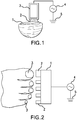
- Figure 1 shows a schematic of an exemplary treatment electrode and nail treatment method in accordance with the disclosure.
- a nail fingernail or toenail
- the treatment electrode 3, which can include a conductor that is encapsulated by a dielectric layer, is placed in contact with the conductive media, 2.
- the treatment electrode is connected to a high-voltage power supply and control system, 4, which is connected to an electrical ground, 5.
- Figure 2 shows a schematic of an electrode structure that can treat multiple nails at one time.
- the electrode support structure, 1, has multiple treatment heads, 2, which are placed and sized appropriately to address individual nails, 3.
- the electrode support structure, 1, is connected to a high voltage power supply and control system, 4, which is connected to ground, 5.
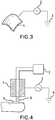
- Figure 3 shows a schematic of a flexible or semi-flexible treatment electrode. This flexible or semi-flexible treatment electrode, 1, can be bent to conform to the shape of the target nail structure (not shown).
- the treatment electrode, 1, is connected to a high voltage power supply and control system , 2, which is connected to an electrical ground, 3.
- Figure 4 shows a schematic of a plasma jet device.
- the treatment electrode, 1, is connected to a gas supply, 2, which provides a stream of gaseous media that is excited into a plasma state when the high voltage power supply and control system, 3, is activated.
- the high voltage power supply and control system, 3, is connected to an electrical ground, 4. Note that in this case, no external conductive media is needed to be applied to the nail, 5, because the gas supply (which becomes a plasma, 6) provides this conductive function.
- the treatment electrode may include multiple materials and have multiple shapes and surface finishes.
- Some example materials include aluminum or other conductor and alumina (Al 2 O 3 ) dielectric, copper or other conductor and silicon nitride dielectric, conductor and quartz dielectric, conductor with rubber or plastic dielectrics (such as a metal conductor with silicone or epoxy with or without glass reinforcement), and conductor with a foam dielectric (such as silicone, polyurethane, or polyethylene foam).
- Al 2 O 3 aluminum or other conductor and alumina dielectric
- copper or other conductor and silicon nitride dielectric copper or other conductor and silicon nitride dielectric, conductor and quartz dielectric
- conductor with rubber or plastic dielectrics such as a metal conductor with silicone or epoxy with or without glass reinforcement
- conductor with a foam dielectric such as silicone, polyurethane, or polyethylene foam.
- the choice of the dielectric material is based on the dielectric breakdown strength, dielectric constant, and the intended duration of usage.
- the pores of the foam are designed such that a microdischarge may form in each of a plurality of pores. These microdischarges are sufficiently numerous such that no individual microdischarge has sufficient energy to cause damage, pain, erythema, or irritation.
- the dielectric layers have a minimum thickness of about 10 microns and are attached to the conductor, for example, by molding, laminating, bonding, brazing, welding, mechanical joining. Alternatively, the dielectric layer may be applied via a coating process, such as anodizing or thermal spraying or by an oxidation process.
- the shape of the conductor may be flat or curved, which will affect the distribution, location and intensity of the plasma created.
- the treatment electrode may have the same size or substantially the same size as the desired treatment area, in which case the operator can apply the electrode in contact with the desired treatment area and maintain its position for the duration of treatment.
- the connection of the treatment electrodes to the electrical support structure may be rigid or adjustable.
- one or more of the following exemplary techniques can be used:
- small openings or holes can be defined in the dielectric layer. These holes can change the nature of the plasma discharge.
- the characteristic dimension of the microdischarges is on the order of 100 to 200 microns (diameter).
- the hole diameter is significantly smaller than the microdischarge diameter, the amount of current that can be passed through the hole to the electrode can be significantly restricted permitting generation of non-thermal plasma possibly even without AC voltage waveform typical of a dielectric barrier discharge.
- the pulse duration can use any suitable voltage and be between about 0.010 seconds and about 0.10 seconds. In accordance with another embodiment, the pulse duration is between about 0.0010 seconds and about 0.010 seconds. In accordance with still another embodiment, the pulse duration is between about 0.00010 seconds and about 0.0010 seconds. In accordance with yet another embodiment, the pulse duration is between about 0.000010 seconds and about 0.00010 seconds. In accordance with another embodiment, the pulse duration is between about 0.0000010 seconds and about 0.000010 seconds. In accordance with still another embodiment, the pulse duration is between about 0.00000010 seconds and about 0.0000010 seconds.
- the pulse duration is between about 0.000000010 seconds and about 0.00000010 seconds. In accordance with still a further embodiment, the pulse duration is between about 0.0000000010 seconds and about 0.000000010 seconds. In accordance with yet a further embodiment, the pulse duration is between about 0.00000000010 seconds and about 0.0000000010 seconds. In accordance with another embodiment, a waveform is provided with a combination of pulses selected from the durations set forth above. Use of pulses of such short duration are believed to result in decreased streamer (microdischarge) formation on the basis that the pulse is too short for the plasma to organize itself in a manner in which it can form a streamer (microdischarge).
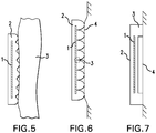
- the disclosure provides systems and methods for generating surface plasmas and techniques for applying surface plasmas to a patient's tissue (e.g., nail).
- tissue e.g., nail
- the treatment device includes a handle (not shown) and a treatment electrode including a conductor 1 surrounded at least in part by an insulating material 2 defining an outer surface that may be placed in direct contact with a patient's tissue (e.g., nail) 3.
- the treatment device is used in this embodiment by applying a voltage to the conductor 1 such that a surface plasma is generated along the surface of the insulating material and between the surface of the insulating material 2 and patient's nail in areas where they are not in direct physical contact, and a gap is defined between the nail and the insulating material.
- the behavior of surface plasma is affected by a variety of variables, including the type and overall shape of insulating material 2 used, as well as the characteristics of surface of the insulating material 2.
- the insulating material can be rigid or flexible. If flexible, insulating material 2 can be, for example, a silicone compound, synthetic rubber, polyurethane, or polyethylene. These can be applied to the conductor via lamination or the conductor can be plated or otherwise sprayed onto the base insulating material. If rigid, insulating material can be a moldable material, such as PTFE, PVDF, PC, PP and the like, and can be molded such as by injection molding. As will be appreciated, the texturing of the surface will have a surface finish that can be a result of the molding process or other processing.
- a mold having a surface finish in accordance with SPI/SPE A1, A2, A3, B1, B2, B3, C1, C2, C3, D1, D2 or D3 can be used.
- the mold can have a first, rougher, surface finish in one region, and a second, smoother surface finish in another region.
- the resulting surface of material 2 facing and/or contacting the tissue (e.g., nail) of the patient/user can be provided with a surface having a region with a mean surface roughness Ra between about 0.01-2000 microinches, 0.1-1000 microinches, 1-100 microinches, 5-50 microinches, 20-40 microinches, 100-200 microinches, 75-125 microinches, 1-4 microinches, 4-8 microinches, 8-12 microinches, 12-20 microinches, 20-30 microinches, 30-40 microinches, 40-50 microinches, 50-60 microinches, 70-80 microinches, 80-90 microinches, 90-100 microinches, or the like.
- the surface of insulating material 2 that faces and/or contacts a user's/patient's tissue can be provided with one or more bumps, ridges or undulations 78 that are distinct and on a generally larger scale than the surface finish, having an average height of about 0.01mm-5mm, 0.1-0.5 mm, 0.5-1.0mm, 1.0-1.5mm, 1.5-2.0mm, 2.0-2.5mm, 2.5-3.0mm, 3.0-3.5mm, 3.5-4.0mm, 4.0-4.5mm, or 4.5-5.0mm, among others.
- Distances between adjacent bumps, ridges or undulations for the foregoing examples can be between 0.01mm-5mm, 0.1-0.5 mm, 0.5-1.0mm, 1.0-1.5mm, 1.5-2.0mm, 2.0-2.5mm, 2.5-3.0mm, 3.0-3.5mm, 3.5-4.0mm, 4.0-4.5mm, or 4.5-5.0mm, among others.
- the material of the dielectric can also be provided with pores. These pores can serve as microcavities for a plasma microdischarge. These pores may be connected to one another or be separate and distinct. Such pores could be regular, as in a capillary array, or irregular in distribution.
- the shape of the pores may be spherical, cylindrical, or other.
- the pores have a characteristic dimension of 0.001 to 0.100 mm, 0.100 to 0.5 mm, 0.5 to 1.0 mm, 1.0-1.5 mm, 1.5-2.0 mm, 2.0-2.5mm, 2.5-3.0mm, 3.0-3.5mm, 3.5-4.0mm, 4.0-4.5mm, or 4.5-5.0mm, among others.
- insulating material can be a semiconductor material. Concentration of charge carriers (consisting of valence and conduction electrons) in semiconductors can be modulated in a variety of ways including changes in temperature, incident light and electric field inside the material. The semiconducting material properties at different locations can also be controlled through incorporation of impurities that create either excess of conduction or excess of valence electrons. Modulating charge carrier density within the semiconducting material permits to exercise control over current being delivered into the plasma. Charge carrier density within the semiconductor may also change its electron emission capabilities and the manner in which insulating material acts as an electron emitter. Furthermore, charge carrier density within the semiconducting material may result in changes of surface breakdown enabling control over surface plasma discharge on semiconductor surface.
- insulating material 2 can have a variety of different dielectric breakdown strengths, such as rubber (450 - 700 V/mil), Teflon (1500 V/mil), glass (2000 - 3000 V/mil), alumina (300 - 500 V/mil), polyimide (12000 - 18000 V/mil), PVDF (1700 V/mil), PVC, polyurethane, UHMW polyethylene, etc.
- rubber 450 - 700 V/mil
- Teflon 1500 V/mil
- glass 2000 - 3000 V/mil
- alumina 300 - 500 V/mil
- polyimide (12000 - 18000 V/mil
- PVDF 1700 V/mil
- PVC polyurethane
- UHMW polyethylene etc.
- air has a dielectric breakdown strength of approximately 20 V/mil.
- the choice of the dielectric thickness is determined by the magnitude of the applied voltage, the gap between the dielectric and the tissue (or the profile of the dielectric, in the case of a surface discharge), the thickness of the nail plate, and the local surface profile of the tissue (which includes tissue surface roughness and topographical variations due to swelling, scarring, or gross curvature of the body).
- a typical thickness of approximately 0.010 to 4 mm for the dielectric layer is suitable to account for the variations in the applied voltage, electrode-tissue separation, tissue surface profile, etc.
- the smaller the gap the smaller the dielectric thickness that is required.
- the minimum gap between the dielectric and the tissue can be determined according to the Paschen curve, which shows the relationship between the breakdown voltage of a gas as a function of its pressure times the characteristic distance.
- the characteristic distance is the air gap between the dielectric and the tissue.
- the Paschen curve provides that minimum voltages of approximately 400 to 6000 volts are useful to generate a breakdown for gaps of approximately 0.01 to 1 mm, respectively.
- significantly higher voltages are useful for generating plasma while overcoming the variations induced by the tissue surface roughness, tissue impedance variations, and local topographical variation of the tissue.
- Such voltages range, for example, from about 500 to about 1000 volts, about 1000 - about10000 volts, and about 10000 - about 50000 volts.
- additional features are provided to facilitate the use of plasma treatment devices by lightly trained or untrained operators.
- the tissue e.g., nail
- a spacer made from a non-conductive material can be used to set the distance between the plasma treatment electrode and the tissue, as shown in Figure 7 , for example.
- the spacer/spacing means can be provided around the periphery of the treatment electrode, in which case it can also surround or encapsulate the local gas. By surrounding the local gas, the structure can facilitate concentration of the heat and reactive species in the desired treatment area.
- Such a border can also incorporate an ozone-absorbing material, such as carbon black, to absorb the ozone that is commonly generated by the dielectric barrier discharge.
- an ozone-absorbing material such as carbon black
- a line, group of lines, a polygon or polygons, a post or a plurality of posts, such as in the form of an array, or other geometries at or around the central portion of the treatment area can be included in the electrode insulating material to prevent the tissue from rising up inside the region defined by the spacer, which would adversely affect the maintenance of a constant gap between the treatment electrode and the body.
- the spacer itself can be mounted on a spring or other resilient member that provides a defined preload contact force between the plasma treatment electrode and the tissue.
- an overload protection interlock such as a contact or proximity switch or sensor
- the size of the microcavities is preferably small enough such that the spacing between the tissue and the plasma treatment electrodes can be controlled without additional spacing means, springs, or other mechanisms, as desired.
- the electrical output is delivered by a power supply and affects the nature of the plasma that is emitted.
- Thermal and non-thermal plasmas may be used.
- the power supply can be connected to a control system that provides control means (e.g., a controller) that controls turning the device on an off, and may be used to control the dose (or intensity) of the plasma, which can in turn be controlled by adjusting the gas flow rate, applied voltage and hence applied current, and the like.
- control means e.g., a controller
- the dose (or intensity) of the plasma which can in turn be controlled by adjusting the gas flow rate, applied voltage and hence applied current, and the like.
- a variety of controls are preferably employed.
- a temperature sensor thermocouple or infrared sensor, for example
- the electrode can contain a fuse or fast circuit breaker to ensure that the current does not increase dramatically as a result of electrode damage, which can cause significant pain to the patient. This fuse or circuit breaker can also be mounted within the power supply.
- the controller can control a second set of conductors proximate the plasma emitters to provide a magnetic field proximate the plasma to help influence the direction of flow of the plasma as well as its density, particularly the density of free electrons within a given volume containing the tissue to be treated.
- Electromagnets and/or permanent magnets can be used, for example, to apply a dipole magnetic field across the tissue, thus providing magnetic field lines that are substantially oblique to the nail, thus influencing the motion of reactive species across the tissue being treated.
- the electrodes that are used to generate the plasma are optionally configured to deliver the electrical energy simultaneously or sequentially.
- the entire plasma emitter may be excited at one time or sequentially in lines, or sub-regions may be excited sequentially (or at the same time or substantially the same time, if desired).
- the control system further provides the means (by way of software or hard-wired) to excite the electrodes in the desired sequence.
- the electrodes or sets of electrodes are individually addressable by the control system.
- the control system provides the means to vary the intensity and duration of the exposure to the plasma. This variation is applied spatially, allowing the user to deliver different plasma exposure doses to different regions of the target nail or nails.
- the gas delivery from a gas supply can be controlled by a valve or set of valves.
- the operator opens the valve to provide continuous gas flow.
- the valve or series of valves is electrically controlled via the control system.
- the electrodes are then used to excite the surrounding ambient air to generate the plasma.
- a spacing means/spacer is used to ensure that sufficient air is available to generate the plasma that is to be directed at the nail.
- the spacing means can be a number of cavities, microcavities, microchannels, or other depressions having negative skewness.
- the spacing means can have positive skewness, such as posts, pillars, raised lines, or other structures that extend above the main surface of the device.
- the spacing means also provides isolation of the electrodes from the nail.
- a flexible electrode is applied directly to the nail.
- a conductive gel is optionally applied prior to application of the flexible electrode.
- Such conductive gel may be integrated into an adhesive patch thereby enabling simultaneous application of the electrode and the gel.
- sensitizing and/or blocking materials can be used to provide differential dosing for different sections of the nail.
- sensitizing materials can include water-based creams, ointments, lotions, sprays, gels, or other fluids. They can also include hydrophilic materials, such as glycerin, which can be used to attract water and water-based materials. These fluids are preferably applied topically.
- the sensitizing materials can act in a variety of ways. These ways include promoting the generation of higher concentrations of specific reactive species, promoting emission of particular light wavelengths, modulating the electric field strength and direction, or other.
- fluids such as hydrogen peroxide, saline, antioxidants such as N-acetyl cysteine (NAC) and others can react with the plasma to generate a variety of reactive species.
- suitable fluids are described, for example, in International Patent Application No. PCT/US2011/046382, filed August 3, 2011 which is incorporated by reference herein in its entirety for any purpose whatsoever. These fluids may also become highly acidic, continue to penetrate the nails post-treatment, and thereby enhance the pathogen killing efficacy.
- the sensitizing material can include organic materials, as well as being in a gaseous, gelatinous or liquid state.
- the sensitizing material may likewise include an amino acid such as Cysteine.
- the sensitizing material is dissolved in a liquid. Suitable liquids include saline, deionized water, phosphate buffered saline, or a combination thereof.
- the amount of organic material in the sensitizing material may vary. In certain embodiments, the organic material in the is at a concentration of at least about 2.5 mM. In other embodiments, the organic material in the sensitizing material is at a concentration of at least about 5 mM. In still other embodiments, the organic material in the sensitizing material, or composition, is at a concentration of at least about 10 mM.
- the blocking materials can include anhydrous (such as oil-based) creams, ointments, gels, or other fluids. They can also include hydrophobic materials which are used to repel water and water-based materials.
- An exemplary illustrative method can have the following steps:
- heat, ultraviolet light, and/or infrared radiation can be applied in concert with the plasma in order to further accelerate the killing of pathogens.
- topical and/or systemic drugs can be used in synergistic combination with the plasma treatment in order to further increase the effectiveness and speed of killing the pathogens. If thermal plasma or heat enhancements such as infrared radiation are employed, it may be desirable to cool the tissue surrounding the nail for greater patient comfort. The tissue may be cooled by flowing or spraying water or cryogen at it.
- a plasma sensitizer can also be used.
- the sensitizer can act as a conductive fluid to direct the plasma in a desired direction, such as toward the nail.
- the sensitizer can additionally or alternatively provide chemicals that react with the plasma, thereby enabling other reactions with the nail to occur. This can result in faster reactions at the nail.
- Suitable materials to be used as sensitizers can include, for example, water, saline, deionized water, or any fluid containing organic compounds, as well as materials including antioxidants.
- a layer containing an exposure indicator is applied to the plasma treatment electrode.
- the exposure indicator can contain one or more compounds that react to the exposure from plasma such that the exposure can be detected and/or metered upon removal from the tissue.
- the indicator may change color or otherwise provide a visual indication of exposure. This change may occur immediately or after exposure to a developer or other chemical.
- An example of an exposure indicator is a photosensitive material that responds to the light emitted by the plasma.
- Another example of an exposure indicator is a material that changes color upon exposure to different pH levels or other chemical species, such as litmus paper. A combination of different materials may be employed to indicate different exposure levels. Such materials can be provided in sheet form, and can be replaced with each subsequent use of the treatment device if the device is otherwise intended to or capable of being reusable.
- the exposure level is monitored automatically using optical sensors, electronic sensors, or a combination thereof.
- the optical sensors for example, can detect visible, ultraviolet, or infrared emissions from the plasma.
- the electrical sensors can detect current flow or electrical field variation and the like as generated by the plasma emission.
- the information from these sensors can then be delivered to the power supply and control system to enable closed loop control of the exposure dose and intensity.
- closed loop control may be desirable to account for patient-specific anatomical or disease variations that affect the plasma intensity, for example.
- the gas delivery from the gas supply can be controlled by a valve or set of valves. In one embodiment, the operator opens the valve to provide continuous gas flow. In an alternate embodiment, the valve or series of valves is electrically controlled via the control system.
- the power supply and control system are connected to the electrode by a high-voltage cable.
- This cable preferably has sufficient length to enable targeting any single portion of the body or multiple areas of the body.
- the electrode dimensions and weight are set so to enable comfortable hand gripping while a plastic or other insulating material shields the operator from any high-voltage exposure.
- the electrode may be curved (i.e. to match or nearly match the curvature of the desired treatment) and/or flexible (as shown in Figure 7 ).
- a treatment electrode can have a variety of shapes, including squares, circles, rectangles, and the like that enable it to conform to the desired treatment area while maintaining the desired gap or surface discharge configuration as appropriate.
- the shape may be standardized for all patients or custom-made based on casting, molding, optical scanning or other measurement methods to create an electrode that more precisely conforms to the anatomy of the specific patient to be treated.
- the electrode, power supply and control system can be integrated into a single handheld unit. This unit optionally contains batteries and/or a cable port to connect to a wall outlet.
- heat, ultraviolet light, visible light, and/or infrared radiation can be applied in concert with or in alternating fashion with the plasma in order to further accelerate the killing of pathogens, alleviation of inflammation, and/or activation of other cellular processes and chemistry.
- topical and/or systemic drugs can be used in synergistic combination with the plasma treatment in order to further increase the effectiveness and speed of killing and/or other reactions.
- the electrode itself is heated and thereby provide conductive heating of the tissue, which can combine with the non-thermal plasma to enhance the effectiveness and speed of killing and/or other reactions.
- tissue surrounding the treatment area may be cooled by flowing or spraying water or cryogen at it.
- the electrode when it is in contact with the tissue being treated, it can be cooled and thereby provide conductive cooling to the local tissue region being treated.
- after-care creams, gels, or other materials may be applied to the treated tissue to help alleviate or repair pain, irritation, erythema, or other unwanted effects, such as cellular or DNA damage.
- anti-oxidants may be used to help reduce post-treatment levels of reactive oxygen species and promote DNA repair.
- a plasma sensitizer can also be used.
- the sensitizer can act as a conductive fluid to direct the plasma in a desired direction, such as toward the tissue (e.g., nail).
- the sensitizer can additionally or alternatively provide chemicals that react with the plasma, thereby enabling other reactions with the tissue to occur. This can result in faster reactions at the tissue.
- Suitable materials to be used as sensitizers can include, for example, water, saline, deionized water, or any fluid containing organic compounds, as well as materials including antioxidants.
- the plasma sensitizing fluid can also be delivered to the tissue as part of the device construction.
- the device can contain a spray, sponge or vapor (aerosolized fluid) jet that has the sensitizing fluid and controllably releases said fluid as desired by the user or automatically upon contact by the electrode to the tissue.
- a moistened fabric may be placed between the electrode and the tissue. In this case, the discharge will occur within the cloth and excessive streamer formation will also be avoided.
- a grounding (dispersive) pad proximately located to the plasma emitter.
- Such pads are commonly used in conjunction with electrosurgical devices.
- the current density As the current transmission increases, there is a higher risk of burning the tissue. The risk of creating tissue burns depends on the amount of current divided by the area over which it is distributed, which is also known as the current density. Nominally, the current density at the ground pad is defined by the area of the pad.
- remote monitoring of the pad attachment can be employed as follows. First, two or more pads or pad sections can be attached to the body in close proximity to one another. These pads can have matching connectors and a cable or cables that run back to the power supply and control system. Prior to and during treatment, the power supply and control system can send a small amount of current via one of the conductive pathways to one of the ground pads. It then measures the return current that is conducted by the second ground pad to determine the overall impedance of the system. If the measured impedance deviates from the nominal value, then the power supply and control system prevents the treatment from starting and/or interrupts the treatment. An indicator means (visual, audible, etc.) is provided on the power supply and control system to inform the operator that the grounding pad(s) are not fully attached to the body.
- the grounding pad(s) may be integrated with the plasma emitter. Such a construction may provide advantages in ease of application to the body, convenience, and/or lower cost.
- the grounding pad can be provided within the plasma emitter, for example, by providing a grounding conductor that is mounted around the periphery or other non-treatment areas of the plasma emitter. This grounding conductor is optionally mounted to the tissue via a conductive tissue adhesive or gel. This conductor can be connected to the power supply through a separate connector. As in the previous discussion, it is possible to monitor the connection (and thereby the overall current density) of the patch by sending a small current to the grounding pad(s) and measuring the return current to determine the overall impedance.
- the plasma emitter can be connected to the power supply by a variety of techniques. For example, short wires having an external connector may be laminated, glued, soldered, or crimped onto the conductive layer of the flexible plasma emitter. Alternatively, a variety of connectors may be mounted (via soldering, lamination, or gluing) on the conductor of the plasma emitter. These can include, for example, snap connectors, surface mount connectors, pin holes, crimp or clamps connectors, among others. Finally, the conductor of the flexible plasma emitter can be formed into one half of a connector, such as a conductive tab or pin.
- the plasma emitter can be attached to the treatment area through a variety of fasteners/attachment techniques, including hook and loop fastener, straps, and tissue adhesives.
- the tissue adhesives may be single-use or multi-use, such as in the case of hydrogels.
- Applicant recently demonstrated the ability of cold atmospheric pressure plasma to kill T. rubrum, the fungus most frequently associated with onychomycosis, in vitro in a simulated nail model.
- 0.7 x 0.7 cm sections of 317.5 micron thick shim stock were cut and double washed in ethanol for 10 minutes.
- 1 ml of stock T. rubrum was homogenized with 4 ml of sterile SDM (Sabouraud Dextrose media).
- the sterile shim stock was placed in 5 ml solution of T. rubrum and inoculated for 2 hours. After removing the shim stock from solution, it was plasma treated for varying time and frequency settings: 1.5 or 3 kHz, 30 seconds or 3 minutes. The treated shim stock was then placed on an SDA (agar) plate to grow overnight.
- SDA agar
- T. rubrum and other organisms can often infect the nail bed or infect sections within the nail plate. Like earthworms tunneling through dirt, these fungi can consume the keratin within the nail plate, leaving microscopic pockets within the nail plate. Accordingly, Applicant conducted tests to demonstrate whether atmospheric pressure plasma could be generated within microscopic air gaps of a similar size to those found within nail plates.
- Figures 8a-b respectively illustrate side and top views of an experimental assembly to test generation of plasma within small gaps ranging in size from 12 to 50 microns.
- the gaps were created using shim stock and glass slides, which were then embedded in gel (to avoid generation of plasma along the periphery).
- the mesh was connected to ground and used as a transparent electrode to enable visualization of plasma formation within the gap.
- two glass slides were epoxied together, separated by two pieces of shim stock having thicknesses of 50, 25 and 12.5 microns. In each case, a high voltage electrode was brought into contact with one side of the glass slides and a mesh was placed on the other side and connected to ground. The entire construction was then embedded in a gel. The mesh was used to enable visualization of the plasma through the glass slide.
- Figure 9 presents photographic evidence of plasma discharge formation within the small gaps at varying thicknesses from about 12.5 to about 50 microns. Applicant notes that the discharge is likely non-uniform due to small differences in the gaps, surface effects or other variations that could cause local concentrations of electric field. These non-uniformities can be easily overcome through appropriate design of the electrodes and power supplies. As shown in Figure 2 , plasma was successfully generated within each of the gaps, evidencing that plasmas can by analogy be generated in nail structures that are infected with T. rubrum and/or other organisms.
- nail plates were harvested from human volunteers. Control samples were taken, sliced into 50 micron thick slices with a cryotome and cultured, confirming infection throughout the nail plate with T. rubrum. The remaining samples were treated with a pulsed dielectric barrier discharge at a frequency of approximately 200 - 300 Hz and a voltage of 20 kV for a duration of 5 minutes. The nail plates were treated three times for this duration. The first time, the nail plate was treated face up and then face down. The third time, the nail plate was embedded in a gel in order to enable generation of plasma within gaps in the nail plate. In all cases, the nail clippings were treated in their "dry" state.
- the samples were frozen and then sliced into 50 micron thick slices with a cryotome. The slices were then placed on agar and incubated as before. Table 2 below shows the number of days that elapsed until growth was seen on each slice. As shown, nearly all slices in the control sample grew by day 2, whereas the treated samples took an average of 7 days to grow. It is known that vegetative T. rubrum populations will double on average every 4.5 hours. Accordingly, this delay in growth represents approximately 4 - 5 log reduction in the fungal population.
- Table 2 Days to observable growth for- control (untreated) and plasma-treated nail clippings (clinically infected with T. rubrum. The experiment was monitored for 13 days. The 'X' denotes that no growth was observed after 13 days. The average growth is computed for all samples. The adjusted average growth is calculated based on the assumption that all remaining samples grew on Day 14.
- this fungus is estimated to double in population every 4.5 hours. So, if nothing grew after about 7-8 days, this corresponds to at least 6 log reduction.
- Applicant has developed a technology to deliver atmospheric DBD plasma to toenails with a convenient disposable electrode.
- the Plasma PinTM device is applied to the tissue (e.g., nail) and connected to a high voltage power supply and control system, as shown in Figure 10 .
- This power supply generates the electric field characteristics within the patch that are necessary to initiate the formation of non-thermal DBD plasma proximate to the nail and within the nail.
- the control system has settings to enable the user to vary the intensity of the plasma as desired.
- plasma forms as a result of the electric field generated between the pin and the nail plate or nail bed below the contact point. It forms along the surface of the dielectric (silicone in this embodiment) and travels down towards the nail plate. Based on laboratory studies, Applicant believes that the plasma also forms within air pockets that may be within the nail plate or nail bed.
- the plasma serves as a conductor, but at relatively low current is much lower ( ⁇ 1 milliamp) and, as described above, this non-thermal plasma can be operated in a regime where no damage to tissue (e.g., nail) is observed even over treatment times as long as 20 minutes. Moreover, this current is distributed over a large area (e.g., about 27 sq. mm). By virtue of this moderate local current density, it is expected that the intensity and severity of any side effects will be moderate to the extent that they occur.
- treatment steps for applying the plasma to a subject it is contemplated that the following steps can be used: 1. Clean the target treatment site (e.g., nail) for treatment with isopropyl alcohol and allow to dry. 2. Connect the plasma emitter device to its power supply. 3. Connect a Grounding Pad (if provided) to the Ground wire of the Power Supply. 4. Apply the Grounding Pad to skin next to the tissue (e.g., toenail) to be treated. 5. Apply "Dry" Treatment:
- dry and wet treatments can be applied exclusively from the other, or in any desired succession. It will be further appreciated that an electric field alone and/or in combination with plasma can be applied to treat the onychomycosis.
- Applicant performed in vitro testing on nail clippings using wet and dry techniques to gage their relative efficacy. Two nail control clippings were set aside and then three 3 samples each were treated for 5 minutes per sample using the a power supply at two different pulse repetition frequencies (approx. 400, 800 Hz) and using the same applied voltage (20kV). All of these treatments were done dry (i.e., without adding additional water). Then the experiment was repeated (3 samples each, 2 frequencies) with wet nail samples.
- MOETM Integrated Multimedia Extensions
- database configuration and/or relational model database configuration and/or relational model, data type, data transmission and/or network framework, syntax structure, and/or the like
- various embodiments of the MOETM may be implemented that enable a great deal of flexibility and customization.
- any element expressed as a means for performing a specified function is intended to encompass any way of performing that function including, for example, a) a combination of circuit elements and associated hardware which perform that function or b) software in any form, including, therefore, firmware, microcode or the like as set forth herein, combined with appropriate circuitry for executing that software to perform the function. Applicant thus regard any means which can provide those functionalities as equivalent to those shown herein.
Landscapes
- Engineering & Computer Science (AREA)
- Health & Medical Sciences (AREA)
- Biomedical Technology (AREA)
- Plasma & Fusion (AREA)
- Physics & Mathematics (AREA)
- Life Sciences & Earth Sciences (AREA)
- Nuclear Medicine, Radiotherapy & Molecular Imaging (AREA)
- Radiology & Medical Imaging (AREA)
- Animal Behavior & Ethology (AREA)
- General Health & Medical Sciences (AREA)
- Public Health (AREA)
- Veterinary Medicine (AREA)
- Spectroscopy & Molecular Physics (AREA)
- Pathology (AREA)
- Medicines That Contain Protein Lipid Enzymes And Other Medicines (AREA)
- Electrotherapy Devices (AREA)
- Plasma Technology (AREA)
Applications Claiming Priority (4)
| Application Number | Priority Date | Filing Date | Title |
|---|---|---|---|
| US201161535986P | 2011-09-17 | 2011-09-17 | |
| US201261584399P | 2012-01-09 | 2012-01-09 | |
| PCT/US2012/031923 WO2012106735A2 (fr) | 2011-02-01 | 2012-04-02 | Traitement de la peau assisté par plasma |
| EP12831818.5A EP2760536A4 (fr) | 2011-09-17 | 2012-09-17 | Systèmes, procédés et programmes lisibles par machine pour le traitement des onychomycoses assisté par champ électrique et / ou par plasma |
Related Parent Applications (1)
| Application Number | Title | Priority Date | Filing Date |
|---|---|---|---|
| EP12831818.5A Division EP2760536A4 (fr) | 2011-09-17 | 2012-09-17 | Systèmes, procédés et programmes lisibles par machine pour le traitement des onychomycoses assisté par champ électrique et / ou par plasma |
Publications (1)
| Publication Number | Publication Date |
|---|---|
| EP3199201A1 true EP3199201A1 (fr) | 2017-08-02 |
Family
ID=47883822
Family Applications (2)
| Application Number | Title | Priority Date | Filing Date |
|---|---|---|---|
| EP12831818.5A Withdrawn EP2760536A4 (fr) | 2011-09-17 | 2012-09-17 | Systèmes, procédés et programmes lisibles par machine pour le traitement des onychomycoses assisté par champ électrique et / ou par plasma |
| EP17158902.1A Withdrawn EP3199201A1 (fr) | 2011-09-17 | 2012-09-17 | Systeme pour champ electrique et/ou traitement de l'onychomycose assistee par plasma |
Family Applications Before (1)
| Application Number | Title | Priority Date | Filing Date |
|---|---|---|---|
| EP12831818.5A Withdrawn EP2760536A4 (fr) | 2011-09-17 | 2012-09-17 | Systèmes, procédés et programmes lisibles par machine pour le traitement des onychomycoses assisté par champ électrique et / ou par plasma |
Country Status (3)
| Country | Link |
|---|---|
| EP (2) | EP2760536A4 (fr) |
| JP (1) | JP6124361B2 (fr) |
| WO (1) | WO2013040542A1 (fr) |
Cited By (2)
| Publication number | Priority date | Publication date | Assignee | Title |
|---|---|---|---|---|
| WO2020144486A1 (fr) * | 2019-01-11 | 2020-07-16 | Synergotron D.O.O. | Dispositif de traitement non invasif de maladies et d'affections d'organismes vivants |
| US11013100B2 (en) | 2016-10-10 | 2021-05-18 | University Of Strathclyde | Plasma accelerator |
Families Citing this family (25)
| Publication number | Priority date | Publication date | Assignee | Title |
|---|---|---|---|---|
| US9351790B2 (en) | 2011-09-17 | 2016-05-31 | M.O.E. Medical Devices Llc | Electrode geometries and method for applying electric field treatment to parts of the body |
| JP6317927B2 (ja) | 2012-01-09 | 2018-04-25 | ムー・メディカル・デバイスズ・エルエルシーMoe Medical Devices Llc | プラズマ補助皮膚処置 |
| EP3086838A4 (fr) * | 2013-12-27 | 2017-08-23 | Moe Medical Devices LLC | Application de traitement par champ électrique sur des parties du corps |
| CN103920237B (zh) * | 2014-04-29 | 2016-11-16 | 方墨希 | 一种修复dna氧化损害的装置 |
| US11358002B2 (en) | 2014-05-29 | 2022-06-14 | Raymond R. Blanche | Method and apparatus for non-thermal nail, foot, and hand fungus treatment |
| US9555262B2 (en) | 2014-05-29 | 2017-01-31 | New Skin Therapies, LLC | Method and apparatus for non-thermal nail, foot, and hand fungus treatment |
| GB2528921A (en) * | 2014-08-05 | 2016-02-10 | Linde Ag | Plasma treatment of an infected nail or infected skin |
| DE102014220488A1 (de) * | 2014-10-09 | 2016-04-14 | Inp Greifswald E.V. | Vorrichtung zum Erzeugen eines kalten Atmosphärenplasmas |
| EP3229900A4 (fr) * | 2014-12-10 | 2018-11-14 | Devicefarm Inc. | Appareil et procédé de traitement de l'onychomycose |
| US20180140824A1 (en) * | 2015-05-19 | 2018-05-24 | Plasmacure B.V. | Non-thermal plasma device |
| DE102015117715A1 (de) * | 2015-10-19 | 2017-04-20 | Cinogy Gmbh | Elektrodenanordnung für eine dielektrisch behinderte Plasmabehandlung |
| EP3423152B1 (fr) * | 2016-03-04 | 2021-12-22 | Accure Medical, LLC | 4systèmes de traitement des champignons |
| MX2018011371A (es) * | 2016-03-22 | 2019-02-13 | Koninklijke Philips Nv | Dispositivo de plasma frio para tratar la piel. |
| DE102016108450B4 (de) * | 2016-05-06 | 2020-01-02 | Cinogy Gmbh | Behandlungsanordnung und Verfahren zur Herstellung einer Behandlungsanordnung |
| US10765850B2 (en) | 2016-05-12 | 2020-09-08 | Gojo Industries, Inc. | Methods and systems for trans-tissue substance delivery using plasmaporation |
| IT201600080827A1 (it) | 2016-08-01 | 2018-02-01 | Mcc Sistemi S R L | Apparato e metodo per il trattamento terapeutico di lesioni tissutali. |
| KR101851389B1 (ko) * | 2016-11-07 | 2018-04-23 | 주식회사 현대메디텍 | 휴대용 피부 관리를 위한 플라즈마 이온 발생기 |
| WO2018089577A1 (fr) | 2016-11-10 | 2018-05-17 | EP Technologies LLC | Procédés et systèmes pour la génération de liquide activé par plasma |
| KR101915381B1 (ko) * | 2017-02-10 | 2018-11-05 | 광운대학교 산학협력단 | 피부 밀착형 플라즈마 피부치료 장치 |
| DE102017104852A1 (de) * | 2017-03-08 | 2018-09-13 | Cinogy Gmbh | Flächige flexible Elektrodenanordnung für eine dielektrisch behinderte Plasmaentladung |
| DE102017106570A1 (de) | 2017-03-28 | 2018-10-04 | Cinogy Gmbh | Flächige flexible Auflageanordnung |
| CN108815709A (zh) * | 2017-12-29 | 2018-11-16 | 重庆半岛医疗科技有限公司 | 一种等离子治疗手柄组件和等离子治疗装置 |
| EP3858115A1 (fr) * | 2018-09-26 | 2021-08-04 | L'oreal | Dispositif de génération de plasma froid comprenant des électrodes et des diélectriques |
| JP7269597B2 (ja) * | 2019-01-31 | 2023-05-09 | シャープ株式会社 | 腫瘍治療装置 |
| CN109731226B (zh) * | 2019-03-07 | 2021-03-02 | 华中科技大学 | 一种等离子体灰指甲治疗装置 |
Citations (6)
| Publication number | Priority date | Publication date | Assignee | Title |
|---|---|---|---|---|
| US20060189976A1 (en) * | 2005-01-18 | 2006-08-24 | Alma Lasers International | System and method for treating biological tissue with a plasma gas discharge |
| WO2007022403A2 (fr) * | 2005-08-15 | 2007-02-22 | The Board Of Trustees Of The Leland Stanford Junior University | Therapie genique oculaire utilisant la transfection mediee par avalanche |
| US20080045879A1 (en) * | 2004-05-28 | 2008-02-21 | Georgia Tech Research Corporation | Methods and Devices for Thermal Treatment |
| US20100145253A1 (en) * | 2005-04-25 | 2010-06-10 | Drexel University | Methods for non-thermal application of gas plasma to living tissue |
| US7758537B1 (en) * | 1995-11-22 | 2010-07-20 | Arthrocare Corporation | Systems and methods for electrosurgical removal of the stratum corneum |
| US20100261994A1 (en) * | 2009-04-09 | 2010-10-14 | Rafael Davalos | Integration of very short electric pulses for minimally to noninvasive electroporation |
Family Cites Families (8)
| Publication number | Priority date | Publication date | Assignee | Title |
|---|---|---|---|---|
| JPH10286316A (ja) * | 1997-04-15 | 1998-10-27 | Mecs:Kk | プラズマ化したガスを照射する皮膚組織改善装置 |
| GB0425765D0 (en) * | 2004-11-23 | 2004-12-22 | Gyrus Medical Ltd | Tissue resurfacing |
| US6780178B2 (en) * | 2002-05-03 | 2004-08-24 | The Board Of Trustees Of The Leland Stanford Junior University | Method and apparatus for plasma-mediated thermo-electrical ablation |
| EP1648556A1 (fr) * | 2003-07-14 | 2006-04-26 | Power Paper Ltd. | Procede, appareil et kit de traitement de l'onychomycose au moyen d'un transport electrocinetique de substances |
| JP2005263695A (ja) * | 2004-03-18 | 2005-09-29 | Suiko Giken Kk | 水虫治療薬 |
| NZ544247A (en) * | 2004-12-22 | 2007-06-29 | Omj Ireland Ltd | Phototherapy using psoralen derivatives and a UVB absorber |
| WO2009065046A1 (fr) * | 2007-11-15 | 2009-05-22 | University Of Southern California | Sonde de traitement au plasma |
| EP2223704A1 (fr) * | 2009-02-17 | 2010-09-01 | Max-Planck-Gesellschaft zur Förderung der Wissenschaften e.V. | Dispositif de traitement d'une partie du corps d'un patient avec un plasma non thermique |
-
2012
- 2012-09-17 WO PCT/US2012/055726 patent/WO2013040542A1/fr active Application Filing
- 2012-09-17 JP JP2014530922A patent/JP6124361B2/ja active Active
- 2012-09-17 EP EP12831818.5A patent/EP2760536A4/fr not_active Withdrawn
- 2012-09-17 EP EP17158902.1A patent/EP3199201A1/fr not_active Withdrawn
Patent Citations (6)
| Publication number | Priority date | Publication date | Assignee | Title |
|---|---|---|---|---|
| US7758537B1 (en) * | 1995-11-22 | 2010-07-20 | Arthrocare Corporation | Systems and methods for electrosurgical removal of the stratum corneum |
| US20080045879A1 (en) * | 2004-05-28 | 2008-02-21 | Georgia Tech Research Corporation | Methods and Devices for Thermal Treatment |
| US20060189976A1 (en) * | 2005-01-18 | 2006-08-24 | Alma Lasers International | System and method for treating biological tissue with a plasma gas discharge |
| US20100145253A1 (en) * | 2005-04-25 | 2010-06-10 | Drexel University | Methods for non-thermal application of gas plasma to living tissue |
| WO2007022403A2 (fr) * | 2005-08-15 | 2007-02-22 | The Board Of Trustees Of The Leland Stanford Junior University | Therapie genique oculaire utilisant la transfection mediee par avalanche |
| US20100261994A1 (en) * | 2009-04-09 | 2010-10-14 | Rafael Davalos | Integration of very short electric pulses for minimally to noninvasive electroporation |
Non-Patent Citations (2)
| Title |
|---|
| AYAN H ET AL: "Application of nanosecond-pulsed dielectric barrier discharge for biomedical treatment of topographically non-uniform surfaces; Application of nanosecond-pulsed DBD for biomedical treatment of topographically non-uniform surfaces", JOURNAL OF PHYSICS D: APPLIED PHYSICS, INSTITUTE OF PHYSICS PUBLISHING LTD, GB, vol. 42, no. 12, 21 June 2009 (2009-06-21), pages 125202, XP020158376, ISSN: 0022-3727 * |
| KUCHENBECKER M ET AL: "Characterization of DBD plasma source for biomedical applications", JOURNAL OF PHYSICS D: APPLIED PHYSICS, INSTITUTE OF PHYSICS PUBLISHING LTD, GB, vol. 42, no. 4, 21 February 2009 (2009-02-21), pages 45212, XP020149191, ISSN: 0022-3727, DOI: 10.1088/0022-3727/42/4/045212 * |
Cited By (2)
| Publication number | Priority date | Publication date | Assignee | Title |
|---|---|---|---|---|
| US11013100B2 (en) | 2016-10-10 | 2021-05-18 | University Of Strathclyde | Plasma accelerator |
| WO2020144486A1 (fr) * | 2019-01-11 | 2020-07-16 | Synergotron D.O.O. | Dispositif de traitement non invasif de maladies et d'affections d'organismes vivants |
Also Published As
| Publication number | Publication date |
|---|---|
| EP2760536A4 (fr) | 2015-05-06 |
| JP6124361B2 (ja) | 2017-05-10 |
| WO2013040542A1 (fr) | 2013-03-21 |
| JP2014530046A (ja) | 2014-11-17 |
| EP2760536A1 (fr) | 2014-08-06 |
Similar Documents
| Publication | Publication Date | Title |
|---|---|---|
| US20190321091A1 (en) | Systems and methods for treatment of topical conditions | |
| EP3199201A1 (fr) | Systeme pour champ electrique et/ou traitement de l'onychomycose assistee par plasma | |
| US20140200506A1 (en) | Systems, methods and machine readable programs for electric field and/or plasma-assisted onychomycosis treatment | |
| EP2670477B1 (fr) | Traitement de la peau assisté par plasma | |
| US11724078B2 (en) | Methods and systems for trans-tissue substance delivery using plasmaporation | |
| US20180103991A1 (en) | Device and method for tissue treatment by combination of energy and plasma | |
| JP5319709B2 (ja) | 電気穿孔された細胞を選択的に治療するプラズマ機器 | |
| US20150157870A1 (en) | Shape conforming flexible dielectric barrier discharge plasma generators | |
| US20170246468A1 (en) | Methods and systems for controlling or tuning the electric field generated in skin or tissue during cold plasma skin treatments | |
| Nuccitelli et al. | Nanoelectroablation therapy for murine basal cell carcinoma | |
| US20150151135A1 (en) | Transdermal delivery of dna vaccines using non-thermal plasma | |
| WO2011063798A2 (fr) | Dispositif et procédé servant à produire un plasma pulsé anisotherme sous pression atmosphérique | |
| KR20230114329A (ko) | 비접촉식 전기천공 전극 및 방법 | |
| WO2015116970A1 (fr) | Procédé et appareil pour l'administration intracellulaire et intercellulaire de cellules, médicaments, vaccins et analogues | |
| CN112823035A (zh) | 通过施加非热能治疗皮腺 | |
| ITUB20159823A1 (it) | Apparecchiatura elettromedicale per il trattamento del corpo umano e procedimento di trattamento mediante detta apparecchiatura | |
| KR102409168B1 (ko) | 석션형 고주파 미용기기 | |
| US20180021080A1 (en) | Apparatus for treating skin blemishes with cold plasma | |
| US20150112300A1 (en) | Method for enhanced trans-tissue delivery of therapeutic substances | |
| CN108652966A (zh) | 一种冷等离子体射流针灸装置 | |
| KR20130077135A (ko) | 피부 조직의 치료를 위한 자극 장치 | |
| Babaeva et al. | Dynamics of dielectric barrier discharges over wounded skin | |
| WO2014020584A1 (fr) | Système et procédé de traitement d'un tissu | |
| Chutsirimongkol et al. | Non-thermal atmospheric dielectric barrier discharge plasma, medical application studies in Thailand | |
| CN110101449A (zh) | 大气压低温等离子体痤疮治疗装置 |
Legal Events
| Date | Code | Title | Description |
|---|---|---|---|
| PUAI | Public reference made under article 153(3) epc to a published international application that has entered the european phase |
Free format text: ORIGINAL CODE: 0009012 |
|
| AC | Divisional application: reference to earlier application |
Ref document number: 2760536 Country of ref document: EP Kind code of ref document: P |
|
| AK | Designated contracting states |
Kind code of ref document: A1 Designated state(s): AL AT BE BG CH CY CZ DE DK EE ES FI FR GB GR HR HU IE IS IT LI LT LU LV MC MK MT NL NO PL PT RO RS SE SI SK SM TR |
|
| AX | Request for extension of the european patent |
Extension state: BA ME |
|
| 17P | Request for examination filed |
Effective date: 20180129 |
|
| RBV | Designated contracting states (corrected) |
Designated state(s): AL AT BE BG CH CY CZ DE DK EE ES FI FR GB GR HR HU IE IS IT LI LT LU LV MC MK MT NL NO PL PT RO RS SE SI SK SM TR |
|
| 17Q | First examination report despatched |
Effective date: 20180912 |
|
| GRAP | Despatch of communication of intention to grant a patent |
Free format text: ORIGINAL CODE: EPIDOSNIGR1 |
|
| RIC1 | Information provided on ipc code assigned before grant |
Ipc: A61N 1/18 20060101AFI20191129BHEP Ipc: A61N 1/06 20060101ALI20191129BHEP Ipc: H05H 1/24 20060101ALI20191129BHEP Ipc: A61N 1/44 20060101ALI20191129BHEP Ipc: A61N 5/06 20060101ALI20191129BHEP Ipc: A61N 1/04 20060101ALI20191129BHEP Ipc: A61N 1/40 20060101ALI20191129BHEP Ipc: A61B 18/04 20060101ALI20191129BHEP Ipc: A61N 1/32 20060101ALI20191129BHEP |
|
| INTG | Intention to grant announced |
Effective date: 20200102 |
|
| STAA | Information on the status of an ep patent application or granted ep patent |
Free format text: STATUS: THE APPLICATION IS DEEMED TO BE WITHDRAWN |
|
| 18D | Application deemed to be withdrawn |
Effective date: 20200603 |