EP3198707B1 - Transducteur électrodynamique - Google Patents
Transducteur électrodynamique Download PDFInfo
- Publication number
- EP3198707B1 EP3198707B1 EP15787442.1A EP15787442A EP3198707B1 EP 3198707 B1 EP3198707 B1 EP 3198707B1 EP 15787442 A EP15787442 A EP 15787442A EP 3198707 B1 EP3198707 B1 EP 3198707B1
- Authority
- EP
- European Patent Office
- Prior art keywords
- disc
- magnetic
- claw
- rotatable
- flux
- Prior art date
- Legal status (The legal status is an assumption and is not a legal conclusion. Google has not performed a legal analysis and makes no representation as to the accuracy of the status listed.)
- Active
Links
- 230000005520 electrodynamics Effects 0.000 title claims description 39
- 210000000078 claw Anatomy 0.000 claims description 98
- 230000004907 flux Effects 0.000 claims description 53
- 238000010276 construction Methods 0.000 claims description 7
- 239000007779 soft material Substances 0.000 claims 2
- 239000000696 magnetic material Substances 0.000 description 5
- 238000006243 chemical reaction Methods 0.000 description 3
- 238000004519 manufacturing process Methods 0.000 description 3
- 238000003860 storage Methods 0.000 description 3
- XEEYBQQBJWHFJM-UHFFFAOYSA-N Iron Chemical compound [Fe] XEEYBQQBJWHFJM-UHFFFAOYSA-N 0.000 description 2
- 230000008901 benefit Effects 0.000 description 2
- 230000008859 change Effects 0.000 description 2
- 238000005192 partition Methods 0.000 description 2
- 230000001360 synchronised effect Effects 0.000 description 2
- 230000002411 adverse Effects 0.000 description 1
- 230000000712 assembly Effects 0.000 description 1
- 238000000429 assembly Methods 0.000 description 1
- 230000002457 bidirectional effect Effects 0.000 description 1
- 230000005540 biological transmission Effects 0.000 description 1
- 230000001419 dependent effect Effects 0.000 description 1
- 238000009826 distribution Methods 0.000 description 1
- 230000000694 effects Effects 0.000 description 1
- 230000008030 elimination Effects 0.000 description 1
- 238000003379 elimination reaction Methods 0.000 description 1
- 238000003306 harvesting Methods 0.000 description 1
- 230000006698 induction Effects 0.000 description 1
- 229910052742 iron Inorganic materials 0.000 description 1
- 239000000463 material Substances 0.000 description 1
- 230000006855 networking Effects 0.000 description 1
- 238000005457 optimization Methods 0.000 description 1
- 238000004804 winding Methods 0.000 description 1
Images


Classifications
-
- H—ELECTRICITY
- H02—GENERATION; CONVERSION OR DISTRIBUTION OF ELECTRIC POWER
- H02K—DYNAMO-ELECTRIC MACHINES
- H02K19/00—Synchronous motors or generators
- H02K19/16—Synchronous generators
- H02K19/22—Synchronous generators having windings each turn of which co-operates alternately with poles of opposite polarity, e.g. heteropolar generators
- H02K19/24—Synchronous generators having windings each turn of which co-operates alternately with poles of opposite polarity, e.g. heteropolar generators with variable-reluctance soft-iron rotors without winding
-
- H—ELECTRICITY
- H02—GENERATION; CONVERSION OR DISTRIBUTION OF ELECTRIC POWER
- H02K—DYNAMO-ELECTRIC MACHINES
- H02K1/00—Details of the magnetic circuit
- H02K1/06—Details of the magnetic circuit characterised by the shape, form or construction
- H02K1/22—Rotating parts of the magnetic circuit
- H02K1/24—Rotor cores with salient poles ; Variable reluctance rotors
- H02K1/246—Variable reluctance rotors
-
- H—ELECTRICITY
- H02—GENERATION; CONVERSION OR DISTRIBUTION OF ELECTRIC POWER
- H02K—DYNAMO-ELECTRIC MACHINES
- H02K21/00—Synchronous motors having permanent magnets; Synchronous generators having permanent magnets
- H02K21/02—Details
- H02K21/04—Windings on magnets for additional excitation ; Windings and magnets for additional excitation
- H02K21/042—Windings on magnets for additional excitation ; Windings and magnets for additional excitation with permanent magnets and field winding both rotating
- H02K21/044—Rotor of the claw pole type
-
- H—ELECTRICITY
- H02—GENERATION; CONVERSION OR DISTRIBUTION OF ELECTRIC POWER
- H02K—DYNAMO-ELECTRIC MACHINES
- H02K21/00—Synchronous motors having permanent magnets; Synchronous generators having permanent magnets
- H02K21/12—Synchronous motors having permanent magnets; Synchronous generators having permanent magnets with stationary armatures and rotating magnets
- H02K21/125—Synchronous motors having permanent magnets; Synchronous generators having permanent magnets with stationary armatures and rotating magnets having an annular armature coil
-
- H—ELECTRICITY
- H02—GENERATION; CONVERSION OR DISTRIBUTION OF ELECTRIC POWER
- H02K—DYNAMO-ELECTRIC MACHINES
- H02K21/00—Synchronous motors having permanent magnets; Synchronous generators having permanent magnets
- H02K21/38—Synchronous motors having permanent magnets; Synchronous generators having permanent magnets with rotating flux distributors, and armatures and magnets both stationary
- H02K21/44—Synchronous motors having permanent magnets; Synchronous generators having permanent magnets with rotating flux distributors, and armatures and magnets both stationary with armature windings wound upon the magnets
-
- H—ELECTRICITY
- H02—GENERATION; CONVERSION OR DISTRIBUTION OF ELECTRIC POWER
- H02K—DYNAMO-ELECTRIC MACHINES
- H02K1/00—Details of the magnetic circuit
- H02K1/06—Details of the magnetic circuit characterised by the shape, form or construction
- H02K1/22—Rotating parts of the magnetic circuit
- H02K1/27—Rotor cores with permanent magnets
- H02K1/2706—Inner rotors
- H02K1/272—Inner rotors the magnetisation axis of the magnets being perpendicular to the rotor axis
- H02K1/2726—Inner rotors the magnetisation axis of the magnets being perpendicular to the rotor axis the rotor consisting of a single magnet or two or more axially juxtaposed single magnets
Definitions
- the invention relates to an electrodynamic converter.
- transversal flux machines the distribution of which is low outside the alternators in the automobile.
- the biggest problem with transversal flux machines is their structure, which usually makes the production uneconomically expensive. This is due in particular to the required complicated geometry of the flux-conducting parts.
- Claw pole generators are a special type of transversal flux machines.
- the claw pole generator has been used for some time as an alternator in large numbers (cf., for example DE 10 2007 016 558 and DE 10 2004 032 684 ).
- claw pole generators are in the documents DE 101 06 519 and DE 102 29 198 and a slip-ring claw pole generator in DE 39 17 343 described.
- DE 10 2012 001 114 the embodiment of a stator for a Transversalhne is disclosed.
- a miniaturized claw pole generator is in the document DE 102 17 285 disclosed.
- WO 2013/13575 A1 discloses a motor in which a rotor is formed with a partition wall disposed between a first magnetic body and a second magnetic body. Projections of the partition block gaps between projecting poles of the first magnetic body and projecting poles of the second magnetic body, which are arranged facing each other in the axial direction of a rotary shaft, to prevent air flow in the axial direction. Notches are formed outside the gaps to reduce the volume of the bulkhead to reduce its inertia.
- the document DE 27 27 450 A1 discloses a synchronous motor with at least two coaxial stator, which are each provided with at least one annular coil, said annular coil is enclosed by a magnetic circuit of weichferromagneticianm material, which is formed on the one hand by a rotor with teeth and on the other hand by the annular coil surrounding the stator which terminates in two systems arranged in a circular shape stator teeth, which cooperate with said rotor toothings via air gaps and are shifted with respect to the cooperating rotor toothings over half a tooth pitch distance from each other.
- the document US 4 127 802 A relates to a bidirectional stepping motor comprising toothed rotor and stator arrangements with pole pieces having annular permanent magnets and solenoid coils.
- the object of the invention is to provide an electrodynamic transducer with improved operating characteristics.
- a claw washer is associated with a spool and disposed on one side of the spool.
- the claw disc has a disc member rotatable about an axis of rotation and a disc member fixed relative thereto, the rotatable and fixed disc members having mutually associated claws which alternately occupy magnetic flux closing and non-magnetic flux closing relative positions as the rotatable disc claw member is rotated.
- Another claw washer is associated with the spool and disposed on an opposite side of the spool and has a disc member rotatable about the rotational axis and a disc member fixed relative thereto, the rotatable and stationary disc members having mutually associated claws alternately occupying a magnetic flux closing and a non-magnetic flux closing relative position upon rotation of the rotatable disc member for the further claw disc.
- the electrodynamic transducer has magnetic flux components that have oppositely magnetized magnetic devices and magnetic flux elements of soft magnetic material.
- the electrodynamic converter has a simple and inexpensive to manufacture structure. Miniaturization of the structure is readily possible.
- the axis of rotation is provided by a component which may, for example, be a shaft, in particular a rotor shaft.
- the rotatable disc components can rotate with the shaft.
- the claws are also referred to as tooth elements or teeth, so that then a Zahnelement- or toothed disc is formed.
- the electrodynamic converter may comprise a housing.
- the fixed disc components may be arranged on the housing.
- the housing may be rotatably mounted. In operation, the rotatable disc components can then rotate with the housing.
- the spool can be rotatably mounted about the axis of rotation.
- the coil may be fixed relative to the axis of rotation, for example on the housing.
- the oppositely magnetized magnetic components may have permanent magnets.
- the permanent magnets may be included in the magnetic flux circuit through the claw disk and / or the further magnetic flux circuit through the further claw disk.
- the oppositely magnetized magnetic components may have electrical magnets.
- Electric magnets can be formed for example by means of one or more coils.
- one or more housing parts may be formed as magnetic flux elements of soft magnetic material.
- the housing parts formed from soft magnetic material may include, for example, one or both sides arranged lid.
- a storage device for a shaft may be at least partially formed of a soft magnetic material.
- Claw assemblies formed in the same embodiment on the rotatable disc member of the claw disc and on the rotatable disc member of the further claw disc may be angularly offset from each other.
- the same embodiment of the jaw arrangements can be formed at least with regard to the number and shape of the claws. Alternatively, it may be formed with angular offset between the stationary disc components. In operation, the relative position of the angular offset with each other arranged disc components is fixed.
- the rotatable disc member may be formed as an inboard disc member and the stationary disc member as an outboard disc member.
- mutually associated jaws may oppose each other at least in the magnetic flux closing relative position and be separated by an air gap.
- Claws on the rotatable disc member and the stationary disc member may be formed with circular arc portion-shaped claws. Side edges of the jaws may be parallel to each other.
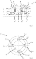
- the claw plate 7 has a rotatable disc component 7 a, which is arranged on the rotor shaft 2.
- a fixed disc member 7b of the claw plate 7 is disposed on the housing 6.
- the further claw plate 8 has a rotatable disc component 8a and a stationary disc component 8b.
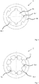
- the Fig. 2 and 3 4 and 5 show possible embodiments for the claw washer 7 and the further claw washer 8.
- the rotatable disk member 7a, 8a is designed as an internal disk component in this embodiment, whereas the stationary disk component 7b, 8b is formed on the outside.
- the disc members 7a, 8a may be fixed and the disc members 7b, 8b may be rotatable (not shown).
- Rotatable and fixed disk component 7a, 7b; 8a, 8b have respective claws 7a.1, 7b.1; 8a.1, 8b.1, which are arranged externally or internally.
- the claws 7a.1, 7b.1; 8a.1, 8b.1 are referred to as teeth or tooth elements.
- a compensation of the cogging torque is achieved in particular in this embodiment by using two mutually offset claw plates 7, 8. If the first is closed, the second is opened. Rotation of the rotor shaft relative to the housing results in closing of the open jaw disc while the closed one is opened.
- the cogging torque results from the lever arm and the reluctance force. The latter is due to the change in the magnetic resistance.
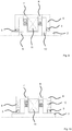
- FIGS. 9 and 10 show axially oppositely magnetized permanent magnets, which are formed as part of the housing 6.
- the oppositely magnetized magnetic elements 9, 10 may also be arranged in the cover 4, 5 or on the rotor shaft 2, which in the FIGS. 9 and 10 is shown.
- the claw plate 7 and the further claw plate 8 are arranged on opposite sides of a coil 11 which is designed as a cylindrical coil in the exemplary embodiment shown.
- the coil 11 When running in the Fig. 1 . 6 . 7 and 9 to 12, the coil 11 is accommodated on the housing 6.
- the coil In the Fig. 1 the coil is firmly connected to the housing. This can be useful if the housing 6 is stationary and the rotor shaft 2 is rotated, since the leads can be easily led out.
- the housing to be rotated it may be advantageous to accommodate the coil 11 on the rotor shaft 2, which Fig. 8 shows. Since the housing 2 is located farther out, it usually has a higher moment of inertia than the rotor shaft 2. This can be rotated while the rotor shaft 2 is fixed, therefore, can have advantages if a large amount of energy to be stored in the rotating part or high Requirements for a smooth running exist.
- the respective magnetic flux represented by arrows A1, A2, B1, B2 runs as a function of the rotational position of the claw disc 7 and the further claw disc 8, through the claw disc 7 (cf. Fig. 7 ) and the further claw plate 8 (see. Fig. 6 ).
- the further claw washer 8 this is just the opposite, which is the result of an angular offset of the magnetic flux closing relative positions for the claw washer 7 on the one hand and the other claw washer 8 on the other.
- the magnetic flux is guided here via the bearing device 3.
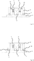
- Fig. 11 shows a schematic representation of an electrodynamic transducer in section, in which magnetic elements by means of electric coils 12, 13 are formed.
- Fig. 12 shows a schematic representation of an electrodynamic transducer in section, in which magnetic elements 3a, 3b of soft magnetic material, the bearing means 3 are provided bridging the magnetic flux.
- the storage device 3 is bridged. This can be useful if the bearings have too high a magnetic resistance or cause eddy currents in the bearing cages to a braking torque.
- Fig. 13 shows a schematic representation of a star-shaped housing cover 20 with coils 21, four of which are shown, for magnetic flux generation for an electrodynamic converter in one of the embodiments explained.
- Fig. 14 shows a perspective view of an electrodynamic transducer.
- Fig. 14 shows a perspective view of an electrodynamic transducer.
- the air gaps between two flux-guiding soft iron components can lie in the different embodiments. These can be manufactured with high precision without increased complexity, whereby the air gap can be set very accurately. This may be another advantage over other concepts in which the permanent magnets co-determine the air gap. These typically have a tolerance of +/- 0.1 mm, which is why the air gap also has large tolerances. This has two adverse effects. On the one hand, the magnetic flux and thus the output power of the generator scatter quite strongly. Also, air gaps deviating from the calculation or over the circumference can disturb the compensation of the cogging torque and thus significantly increase it.
- the magnetic flux from the magnetic elements each selects the path of least magnetic resistance. If a claw disc is closed, almost the entire river runs through it. If the rotor shaft 2 is rotated relative to the housing 6, the two claw disks 7, 8 are offset relative to one another, so that the coil 11 is penetrated by an alternating flow. This leads to the induction of the generator voltage in the coil 11.
- the magnetic flux can also be generated without permanent magnets by two or more coils 12, 13, 21. These can in turn with the housing 6 (see Fig. 11 and 13 ) or the rotor shaft 2 may be connected.
- the electrodynamic transducer it may be useful to wind one or more coils directly on the rotor shaft 2, so as to ensure the manufacturability, without providing a division of the shaft for pushing the coil between the claw plates 7, 8.
- the number and width of the jaws or tooth elements is variable and can be adapted for optimization. Furthermore, the claw shape can be changed by rounding the edges or skew along the longitudinal axis in order to achieve an improved magnetic flux guide at low cogging torques.
- the electrodynamic converter can be used in its various configurations with suitable energization as a motor when at least two units are connected to a shaft or otherwise with each other.
Landscapes
- Engineering & Computer Science (AREA)
- Power Engineering (AREA)
- Reciprocating, Oscillating Or Vibrating Motors (AREA)
- Permanent Field Magnets Of Synchronous Machinery (AREA)
- Electromagnets (AREA)
Claims (12)
- Transducteur électrodynamique (1), avec- une bobine (11),- un disque à griffes (7) attribué à la bobine (11), qui est disposé sur un côté de la bobine (11) et comporte un composant de disque (7a) pouvant tourner autour d'un axe de rotation et un composant de disque (7b) relativement fixe à cet effet, le composant de disque pouvant tourner et le composant de disque fixe (7a, 7b) comportant des griffes attribuées l'un à l'autre, qui adoptent en alternance une position relative fermant le flux magnétique et une position relative ne fermant pas le flux magnétique lors de la rotation du composant de disque pouvant tourner (7a) pour la disque à griffes (7),- un autre disque à griffes (8) attribué à la bobine (11), qui est placé sur un côté opposé de la bobine (11) et comporte un composant de disque (8a) pouvant tourner autour de l'axe de rotation et un composant de disque relativement fixe à cet effet (8b), le composant de disque (8a) pouvant tourner et le composant de disque fixe (8b) comportant des griffes attribuées l'un à l'autre, qui prennent en alternance une position relative fermant le flux magnétique et ne fermant pas le flux magnétique lors de la rotation du composant de disque pouvant tourner (8a) pour l'autre disque à griffes (8), et- des composant à flux magnétique, qui comportent des composants magnétiques axialement opposés, magnétisés de façon contraire (9, 10 ; 12, 13) et des éléments à flux magnétiques dans un matériau magnétique doux, dont, en fonctionnement, au moins une partie est respectivement attribuée à un flux magnétique par le disque à griffes (7) ou à un autre flux magnétique par l'autre disque à griffes (8), qui se constituent en alternance lors de la rotation du composant de disque pouvant tourner (7a) du disque à griffes (7) et du composant de disque pouvant tourner (8a) de l'autre disque à griffes (8),les positions relatives fermant le flux magnétique pour le disque à griffes (7) et l'autre disque à griffes (8) étant formées avec un déport angulaire l'un par rapport à l'autre, tout comme également les positions relatives ne fermant pas le flux magnétique.
- Transducteur électrodynamique selon la revendication 1, caractérisé en ce que les composants magnétiques magnétisés de façon contraire comportent des aimants permanents (9, 10).
- Transducteur électrodynamique (1) selon la revendication 1 ou 2, caractérisé en ce que les composants magnétiques magnétisés de façon contraire comportent des aimants électriques (12, 13).
- Transducteur électrodynamique (1) selon au moins l'une quelconque des revendications précédentes, caractérisé en ce que les composants magnétiques magnétisés de façon contraire comportent des composants magnétiques axialement et/ou radialement magnétisés par rapport à l'axe de rotation.
- Transducteur électrodynamique (5) selon au moins l'une quelconque des revendications précédentes, caractérisé par un boîtier (6), une ou plusieurs parties de boîtier du boîtier (6) étant formées comme des éléments à flux magnétique faits d'un matériau magnétique doux.
- Transducteur électrodynamique (1) selon au moins l'une quelconque des revendications précédentes caractérisé en ce que les éléments à flux magnétique (3a, 3b) sont formés pontant un dispositif de support (3) d'un arbre (2) tournant autour de l'axe de rotation et fermant de ce fait le flux magnétique.
- Transducteur électrodynamique (1) selon au moins l'une quelconque des revendications précédentes, caractérisé en ce que le disque à griffes (7) et l'autre disque à griffes (8) comportent respectivement plusieurs positions relatives fermant le flux magnétique.
- Transducteur électrodynamique (1) selon au moins l'une quelconque des revendications précédentes, caractérisé en ce que des systèmes de griffes, qui sont formés dans la même exécution sur le composant de disque pouvant tourner (7a) du disque à griffes (7) et sur le composant de disque pouvant tourner (8a) de l'autre disque à griffes (8), sont disposés avec un déport angulaire l'un par rapport à l'autre.
- Transducteur électrodynamique (1) selon au moins l'une quelconque des revendications précédentes, caractérisé en ce que pour le disque à griffes (7) et/ou l'autre disque à griffes (8), le composant de disque pouvant tourner (7a ; 8a) est formé comme un composant de disque situé à l'intérieur et le composant de disque fixe (7b ; 8b) comme un composant de disque situé à l'extérieur.
- Transducteur électrodynamique selon au moins l'une quelconque des revendications précédentes, caractérisé en ce que sur le composant de disque pouvant tourner (7a ; 8a) et sur le composant de disque fixe (7b ; 8b) des griffes sont formées avec des griffes en forme de section d'arc de cercle.
- Transducteur électrodynamique selon au moins l'une quelconque des revendications précédentes, caractérisé en ce que dans la position relative fermant le flux magnétique, un interstice est formé dans la direction radiale étant essentiellement constamment large, entre des bords opposés l'un à l'autre des griffes attribuées, qui sont formés sur le composant de disque pouvant tourner et le composant de disque fixe (7a ; 8a ; 7b ; 8b).
- Transducteur électrodynamique selon au moins l'une quelconque des revendications précédentes, caractérisé en ce que la bobine (11) est placé sur un arbre de rotor (2) et peut tourner conjointement avec celui-ci.
Applications Claiming Priority (2)
| Application Number | Priority Date | Filing Date | Title |
|---|---|---|---|
| DE102014113648.9A DE102014113648B4 (de) | 2014-09-22 | 2014-09-22 | Elektrodynamischer Wandler |
| PCT/DE2015/100399 WO2016045663A1 (fr) | 2014-09-22 | 2015-09-22 | Transformateur électrodynamique |
Publications (2)
| Publication Number | Publication Date |
|---|---|
| EP3198707A1 EP3198707A1 (fr) | 2017-08-02 |
| EP3198707B1 true EP3198707B1 (fr) | 2019-07-10 |
Family
ID=54364948
Family Applications (1)
| Application Number | Title | Priority Date | Filing Date |
|---|---|---|---|
| EP15787442.1A Active EP3198707B1 (fr) | 2014-09-22 | 2015-09-22 | Transducteur électrodynamique |
Country Status (5)
| Country | Link |
|---|---|
| US (1) | US10756608B2 (fr) |
| EP (1) | EP3198707B1 (fr) |
| CN (1) | CN107112871B (fr) |
| DE (1) | DE102014113648B4 (fr) |
| WO (1) | WO2016045663A1 (fr) |
Citations (3)
| Publication number | Priority date | Publication date | Assignee | Title |
|---|---|---|---|---|
| US2760093A (en) * | 1953-05-07 | 1956-08-21 | Nat Pneumatic Co Inc | Electric generator |
| DE2727450A1 (de) * | 1976-07-05 | 1978-01-12 | Philips Nv | Synchronmotor |
| US4127802A (en) * | 1977-04-06 | 1978-11-28 | Johnson Milton H | High torque stepping motor |
Family Cites Families (11)
| Publication number | Priority date | Publication date | Assignee | Title |
|---|---|---|---|---|
| DE165101C (fr) * | ||||
| DE3917343C2 (de) * | 1989-05-27 | 2002-08-29 | Bosch Gmbh Robert | Schleifringloser Klauenpol-Generator |
| JPH10513035A (ja) * | 1994-12-21 | 1998-12-08 | ヒル,ヴォルフガング | 横断磁束機械 |
| DE10106519A1 (de) | 2001-02-13 | 2002-08-22 | Bosch Gmbh Robert | Elektrische Maschine |
| DE10217285A1 (de) | 2002-04-12 | 2003-11-06 | Coreta Gmbh | Elektromechanischer Energiewandler |
| DE10229198A1 (de) * | 2002-06-28 | 2004-01-22 | Robert Bosch Gmbh | Elektrische Maschine, insbesondere Drehstromgenerator |
| US20050006972A1 (en) * | 2003-07-07 | 2005-01-13 | Bradfield Michael D. | Twin coil claw pole rotor with segmented stator winding for electrical machine |
| JP2007282420A (ja) | 2006-04-10 | 2007-10-25 | Denso Corp | 車両用交流発電機 |
| DE102012001114B4 (de) * | 2012-01-23 | 2023-03-30 | Sew-Eurodrive Gmbh & Co Kg | Elektromaschine |
| JP5557971B2 (ja) | 2012-04-10 | 2014-07-23 | 三菱電機株式会社 | 電動機 |
| AR089679A1 (es) * | 2013-01-04 | 2014-09-10 | Ricardo Rucci Hugo | Maquina electrica sin colector, con elevado coeficiente de rendimiento |
-
2014
- 2014-09-22 DE DE102014113648.9A patent/DE102014113648B4/de not_active Expired - Fee Related
-
2015
- 2015-09-22 EP EP15787442.1A patent/EP3198707B1/fr active Active
- 2015-09-22 WO PCT/DE2015/100399 patent/WO2016045663A1/fr active Application Filing
- 2015-09-22 US US15/513,063 patent/US10756608B2/en active Active
- 2015-09-22 CN CN201580051101.4A patent/CN107112871B/zh active Active
Patent Citations (3)
| Publication number | Priority date | Publication date | Assignee | Title |
|---|---|---|---|---|
| US2760093A (en) * | 1953-05-07 | 1956-08-21 | Nat Pneumatic Co Inc | Electric generator |
| DE2727450A1 (de) * | 1976-07-05 | 1978-01-12 | Philips Nv | Synchronmotor |
| US4127802A (en) * | 1977-04-06 | 1978-11-28 | Johnson Milton H | High torque stepping motor |
Also Published As
| Publication number | Publication date |
|---|---|
| WO2016045663A1 (fr) | 2016-03-31 |
| DE102014113648B4 (de) | 2017-09-21 |
| US20170331354A1 (en) | 2017-11-16 |
| DE102014113648A1 (de) | 2016-04-07 |
| CN107112871A (zh) | 2017-08-29 |
| CN107112871B (zh) | 2019-12-13 |
| US10756608B2 (en) | 2020-08-25 |
| EP3198707A1 (fr) | 2017-08-02 |
Similar Documents
| Publication | Publication Date | Title |
|---|---|---|
| EP0221228B1 (fr) | Entraînement électrique | |
| DE112006002546B4 (de) | Elektromotor mit asymmetrischen Polen | |
| DE29816561U1 (de) | Doppelseitiger bürstenloser Gleichstrommotor mit NE-Kern und axialem Magnetfeld des Dauermagnettyps | |
| DE112005000091T5 (de) | Elektrische Maschine | |
| DE102021102807A1 (de) | Magneten, Polschuhe und Schlitzöffnungen eines Axialflussmotors | |
| EP0286905A1 (fr) | Moteur à courant continu à commutation électronique | |
| DE102010004887A1 (de) | Spulenkörper zur Montage an einem Magnetkern, Magnetkern für Reluktanzresolver und Verfahren zur Herstellung | |
| DE102017202925B4 (de) | Rotierende elektrische Maschine | |
| EP2770616A1 (fr) | Machine électrique avec stator séparé | |
| DE102017204072A1 (de) | Elektrische Maschine | |
| DE102004025660A1 (de) | Motor unter Verwendung eines Permanentmagneten | |
| DE4310226A1 (de) | Mittels Permanentmagneten erregter elektrischer Motor | |
| EP0940000B1 (fr) | Machine a reluctance diphasee commutee electroniquement | |
| DE102017121410A1 (de) | Drehaktuator | |
| DE102008062025A1 (de) | Schrittmotorvorrichtung | |
| DE102008022209A1 (de) | Wechselstrommotor | |
| DE112019001628T5 (de) | Motor | |
| EP3198707B1 (fr) | Transducteur électrodynamique | |
| DE102020129142A1 (de) | Läufer für eine rotierende elektrische Maschine | |
| EP2149963B1 (fr) | Moteur à spin magnétique | |
| DE102019004428A1 (de) | Elektronisch kommutierter Elektromotor | |
| DE102018101227A1 (de) | Bürsten-Gleichstrommaschine | |
| WO2009121444A1 (fr) | Moteur à pôles à griffes | |
| DE102016208780B4 (de) | Elektromotor | |
| DE102016201094A1 (de) | Elektrische Maschine |
Legal Events
| Date | Code | Title | Description |
|---|---|---|---|
| STAA | Information on the status of an ep patent application or granted ep patent |
Free format text: STATUS: THE INTERNATIONAL PUBLICATION HAS BEEN MADE |
|
| PUAI | Public reference made under article 153(3) epc to a published international application that has entered the european phase |
Free format text: ORIGINAL CODE: 0009012 |
|
| STAA | Information on the status of an ep patent application or granted ep patent |
Free format text: STATUS: REQUEST FOR EXAMINATION WAS MADE |
|
| 17P | Request for examination filed |
Effective date: 20170405 |
|
| AK | Designated contracting states |
Kind code of ref document: A1 Designated state(s): AL AT BE BG CH CY CZ DE DK EE ES FI FR GB GR HR HU IE IS IT LI LT LU LV MC MK MT NL NO PL PT RO RS SE SI SK SM TR |
|
| AX | Request for extension of the european patent |
Extension state: BA ME |
|
| RIN1 | Information on inventor provided before grant (corrected) |
Inventor name: DREYER, ROBERT Inventor name: KELP, MARTIN Inventor name: MOENNICH, OLIVER |
|
| DAV | Request for validation of the european patent (deleted) | ||
| DAX | Request for extension of the european patent (deleted) | ||
| STAA | Information on the status of an ep patent application or granted ep patent |
Free format text: STATUS: EXAMINATION IS IN PROGRESS |
|
| 17Q | First examination report despatched |
Effective date: 20180518 |
|
| GRAP | Despatch of communication of intention to grant a patent |
Free format text: ORIGINAL CODE: EPIDOSNIGR1 |
|
| STAA | Information on the status of an ep patent application or granted ep patent |
Free format text: STATUS: GRANT OF PATENT IS INTENDED |
|
| INTG | Intention to grant announced |
Effective date: 20190130 |
|
| GRAS | Grant fee paid |
Free format text: ORIGINAL CODE: EPIDOSNIGR3 |
|
| GRAA | (expected) grant |
Free format text: ORIGINAL CODE: 0009210 |
|
| STAA | Information on the status of an ep patent application or granted ep patent |
Free format text: STATUS: THE PATENT HAS BEEN GRANTED |
|
| AK | Designated contracting states |
Kind code of ref document: B1 Designated state(s): AL AT BE BG CH CY CZ DE DK EE ES FI FR GB GR HR HU IE IS IT LI LT LU LV MC MK MT NL NO PL PT RO RS SE SI SK SM TR |
|
| REG | Reference to a national code |
Ref country code: GB Ref legal event code: FG4D Free format text: NOT ENGLISH |
|
| REG | Reference to a national code |
Ref country code: CH Ref legal event code: EP Ref country code: AT Ref legal event code: REF Ref document number: 1154544 Country of ref document: AT Kind code of ref document: T Effective date: 20190715 |
|
| REG | Reference to a national code |
Ref country code: DE Ref legal event code: R096 Ref document number: 502015009628 Country of ref document: DE |
|
| REG | Reference to a national code |
Ref country code: IE Ref legal event code: FG4D Free format text: LANGUAGE OF EP DOCUMENT: GERMAN |
|
| REG | Reference to a national code |
Ref country code: NL Ref legal event code: MP Effective date: 20190710 |
|
| REG | Reference to a national code |
Ref country code: LT Ref legal event code: MG4D |
|
| PG25 | Lapsed in a contracting state [announced via postgrant information from national office to epo] |
Ref country code: LT Free format text: LAPSE BECAUSE OF FAILURE TO SUBMIT A TRANSLATION OF THE DESCRIPTION OR TO PAY THE FEE WITHIN THE PRESCRIBED TIME-LIMIT Effective date: 20190710 Ref country code: HR Free format text: LAPSE BECAUSE OF FAILURE TO SUBMIT A TRANSLATION OF THE DESCRIPTION OR TO PAY THE FEE WITHIN THE PRESCRIBED TIME-LIMIT Effective date: 20190710 Ref country code: PT Free format text: LAPSE BECAUSE OF FAILURE TO SUBMIT A TRANSLATION OF THE DESCRIPTION OR TO PAY THE FEE WITHIN THE PRESCRIBED TIME-LIMIT Effective date: 20191111 Ref country code: NL Free format text: LAPSE BECAUSE OF FAILURE TO SUBMIT A TRANSLATION OF THE DESCRIPTION OR TO PAY THE FEE WITHIN THE PRESCRIBED TIME-LIMIT Effective date: 20190710 Ref country code: NO Free format text: LAPSE BECAUSE OF FAILURE TO SUBMIT A TRANSLATION OF THE DESCRIPTION OR TO PAY THE FEE WITHIN THE PRESCRIBED TIME-LIMIT Effective date: 20191010 Ref country code: SE Free format text: LAPSE BECAUSE OF FAILURE TO SUBMIT A TRANSLATION OF THE DESCRIPTION OR TO PAY THE FEE WITHIN THE PRESCRIBED TIME-LIMIT Effective date: 20190710 Ref country code: BG Free format text: LAPSE BECAUSE OF FAILURE TO SUBMIT A TRANSLATION OF THE DESCRIPTION OR TO PAY THE FEE WITHIN THE PRESCRIBED TIME-LIMIT Effective date: 20191010 Ref country code: FI Free format text: LAPSE BECAUSE OF FAILURE TO SUBMIT A TRANSLATION OF THE DESCRIPTION OR TO PAY THE FEE WITHIN THE PRESCRIBED TIME-LIMIT Effective date: 20190710 |
|
| PG25 | Lapsed in a contracting state [announced via postgrant information from national office to epo] |
Ref country code: IS Free format text: LAPSE BECAUSE OF FAILURE TO SUBMIT A TRANSLATION OF THE DESCRIPTION OR TO PAY THE FEE WITHIN THE PRESCRIBED TIME-LIMIT Effective date: 20191110 Ref country code: GR Free format text: LAPSE BECAUSE OF FAILURE TO SUBMIT A TRANSLATION OF THE DESCRIPTION OR TO PAY THE FEE WITHIN THE PRESCRIBED TIME-LIMIT Effective date: 20191011 Ref country code: ES Free format text: LAPSE BECAUSE OF FAILURE TO SUBMIT A TRANSLATION OF THE DESCRIPTION OR TO PAY THE FEE WITHIN THE PRESCRIBED TIME-LIMIT Effective date: 20190710 Ref country code: RS Free format text: LAPSE BECAUSE OF FAILURE TO SUBMIT A TRANSLATION OF THE DESCRIPTION OR TO PAY THE FEE WITHIN THE PRESCRIBED TIME-LIMIT Effective date: 20190710 Ref country code: AL Free format text: LAPSE BECAUSE OF FAILURE TO SUBMIT A TRANSLATION OF THE DESCRIPTION OR TO PAY THE FEE WITHIN THE PRESCRIBED TIME-LIMIT Effective date: 20190710 Ref country code: LV Free format text: LAPSE BECAUSE OF FAILURE TO SUBMIT A TRANSLATION OF THE DESCRIPTION OR TO PAY THE FEE WITHIN THE PRESCRIBED TIME-LIMIT Effective date: 20190710 |
|
| PG25 | Lapsed in a contracting state [announced via postgrant information from national office to epo] |
Ref country code: TR Free format text: LAPSE BECAUSE OF FAILURE TO SUBMIT A TRANSLATION OF THE DESCRIPTION OR TO PAY THE FEE WITHIN THE PRESCRIBED TIME-LIMIT Effective date: 20190710 |
|
| PG25 | Lapsed in a contracting state [announced via postgrant information from national office to epo] |
Ref country code: EE Free format text: LAPSE BECAUSE OF FAILURE TO SUBMIT A TRANSLATION OF THE DESCRIPTION OR TO PAY THE FEE WITHIN THE PRESCRIBED TIME-LIMIT Effective date: 20190710 Ref country code: PL Free format text: LAPSE BECAUSE OF FAILURE TO SUBMIT A TRANSLATION OF THE DESCRIPTION OR TO PAY THE FEE WITHIN THE PRESCRIBED TIME-LIMIT Effective date: 20190710 Ref country code: RO Free format text: LAPSE BECAUSE OF FAILURE TO SUBMIT A TRANSLATION OF THE DESCRIPTION OR TO PAY THE FEE WITHIN THE PRESCRIBED TIME-LIMIT Effective date: 20190710 Ref country code: IT Free format text: LAPSE BECAUSE OF FAILURE TO SUBMIT A TRANSLATION OF THE DESCRIPTION OR TO PAY THE FEE WITHIN THE PRESCRIBED TIME-LIMIT Effective date: 20190710 Ref country code: DK Free format text: LAPSE BECAUSE OF FAILURE TO SUBMIT A TRANSLATION OF THE DESCRIPTION OR TO PAY THE FEE WITHIN THE PRESCRIBED TIME-LIMIT Effective date: 20190710 |
|
| PG25 | Lapsed in a contracting state [announced via postgrant information from national office to epo] |
Ref country code: SK Free format text: LAPSE BECAUSE OF FAILURE TO SUBMIT A TRANSLATION OF THE DESCRIPTION OR TO PAY THE FEE WITHIN THE PRESCRIBED TIME-LIMIT Effective date: 20190710 Ref country code: IS Free format text: LAPSE BECAUSE OF FAILURE TO SUBMIT A TRANSLATION OF THE DESCRIPTION OR TO PAY THE FEE WITHIN THE PRESCRIBED TIME-LIMIT Effective date: 20200224 Ref country code: MC Free format text: LAPSE BECAUSE OF FAILURE TO SUBMIT A TRANSLATION OF THE DESCRIPTION OR TO PAY THE FEE WITHIN THE PRESCRIBED TIME-LIMIT Effective date: 20190710 Ref country code: SM Free format text: LAPSE BECAUSE OF FAILURE TO SUBMIT A TRANSLATION OF THE DESCRIPTION OR TO PAY THE FEE WITHIN THE PRESCRIBED TIME-LIMIT Effective date: 20190710 Ref country code: CZ Free format text: LAPSE BECAUSE OF FAILURE TO SUBMIT A TRANSLATION OF THE DESCRIPTION OR TO PAY THE FEE WITHIN THE PRESCRIBED TIME-LIMIT Effective date: 20190710 |
|
| REG | Reference to a national code |
Ref country code: DE Ref legal event code: R097 Ref document number: 502015009628 Country of ref document: DE |
|
| PLBE | No opposition filed within time limit |
Free format text: ORIGINAL CODE: 0009261 |
|
| STAA | Information on the status of an ep patent application or granted ep patent |
Free format text: STATUS: NO OPPOSITION FILED WITHIN TIME LIMIT |
|
| PG2D | Information on lapse in contracting state deleted |
Ref country code: IS |
|
| PG25 | Lapsed in a contracting state [announced via postgrant information from national office to epo] |
Ref country code: IE Free format text: LAPSE BECAUSE OF NON-PAYMENT OF DUE FEES Effective date: 20190922 Ref country code: LU Free format text: LAPSE BECAUSE OF NON-PAYMENT OF DUE FEES Effective date: 20190922 |
|
| 26N | No opposition filed |
Effective date: 20200603 |
|
| REG | Reference to a national code |
Ref country code: BE Ref legal event code: MM Effective date: 20190930 |
|
| PG25 | Lapsed in a contracting state [announced via postgrant information from national office to epo] |
Ref country code: SI Free format text: LAPSE BECAUSE OF FAILURE TO SUBMIT A TRANSLATION OF THE DESCRIPTION OR TO PAY THE FEE WITHIN THE PRESCRIBED TIME-LIMIT Effective date: 20190710 Ref country code: BE Free format text: LAPSE BECAUSE OF NON-PAYMENT OF DUE FEES Effective date: 20190930 |
|
| PG25 | Lapsed in a contracting state [announced via postgrant information from national office to epo] |
Ref country code: CY Free format text: LAPSE BECAUSE OF FAILURE TO SUBMIT A TRANSLATION OF THE DESCRIPTION OR TO PAY THE FEE WITHIN THE PRESCRIBED TIME-LIMIT Effective date: 20190710 |
|
| PG25 | Lapsed in a contracting state [announced via postgrant information from national office to epo] |
Ref country code: HU Free format text: LAPSE BECAUSE OF FAILURE TO SUBMIT A TRANSLATION OF THE DESCRIPTION OR TO PAY THE FEE WITHIN THE PRESCRIBED TIME-LIMIT; INVALID AB INITIO Effective date: 20150922 Ref country code: MT Free format text: LAPSE BECAUSE OF FAILURE TO SUBMIT A TRANSLATION OF THE DESCRIPTION OR TO PAY THE FEE WITHIN THE PRESCRIBED TIME-LIMIT Effective date: 20190710 |
|
| PG25 | Lapsed in a contracting state [announced via postgrant information from national office to epo] |
Ref country code: MK Free format text: LAPSE BECAUSE OF FAILURE TO SUBMIT A TRANSLATION OF THE DESCRIPTION OR TO PAY THE FEE WITHIN THE PRESCRIBED TIME-LIMIT Effective date: 20190710 |
|
| PGFP | Annual fee paid to national office [announced via postgrant information from national office to epo] |
Ref country code: AT Payment date: 20230915 Year of fee payment: 9 |
|
| PGFP | Annual fee paid to national office [announced via postgrant information from national office to epo] |
Ref country code: CH Payment date: 20231001 Year of fee payment: 9 |
|
| PGFP | Annual fee paid to national office [announced via postgrant information from national office to epo] |
Ref country code: DE Payment date: 20240919 Year of fee payment: 10 |
|
| PGFP | Annual fee paid to national office [announced via postgrant information from national office to epo] |
Ref country code: GB Payment date: 20240923 Year of fee payment: 10 |
|
| PGFP | Annual fee paid to national office [announced via postgrant information from national office to epo] |
Ref country code: FR Payment date: 20240930 Year of fee payment: 10 |
|
| PGFP | Annual fee paid to national office [announced via postgrant information from national office to epo] |
Ref country code: AT Payment date: 20240918 Year of fee payment: 10 |