EP3198707B1 - Electrodynamic transducer - Google Patents
Electrodynamic transducer Download PDFInfo
- Publication number
- EP3198707B1 EP3198707B1 EP15787442.1A EP15787442A EP3198707B1 EP 3198707 B1 EP3198707 B1 EP 3198707B1 EP 15787442 A EP15787442 A EP 15787442A EP 3198707 B1 EP3198707 B1 EP 3198707B1
- Authority
- EP
- European Patent Office
- Prior art keywords
- disc
- magnetic
- claw
- rotatable
- flux
- Prior art date
- Legal status (The legal status is an assumption and is not a legal conclusion. Google has not performed a legal analysis and makes no representation as to the accuracy of the status listed.)
- Active
Links
- 230000005520 electrodynamics Effects 0.000 title claims description 39
- 210000000078 claw Anatomy 0.000 claims description 98
- 230000004907 flux Effects 0.000 claims description 53
- 238000010276 construction Methods 0.000 claims description 7
- 239000007779 soft material Substances 0.000 claims 2
- 239000000696 magnetic material Substances 0.000 description 5
- 238000006243 chemical reaction Methods 0.000 description 3
- 238000004519 manufacturing process Methods 0.000 description 3
- 238000003860 storage Methods 0.000 description 3
- XEEYBQQBJWHFJM-UHFFFAOYSA-N Iron Chemical compound [Fe] XEEYBQQBJWHFJM-UHFFFAOYSA-N 0.000 description 2
- 230000008901 benefit Effects 0.000 description 2
- 230000008859 change Effects 0.000 description 2
- 238000005192 partition Methods 0.000 description 2
- 230000001360 synchronised effect Effects 0.000 description 2
- 230000002411 adverse Effects 0.000 description 1
- 230000000712 assembly Effects 0.000 description 1
- 238000000429 assembly Methods 0.000 description 1
- 230000002457 bidirectional effect Effects 0.000 description 1
- 230000005540 biological transmission Effects 0.000 description 1
- 230000001419 dependent effect Effects 0.000 description 1
- 238000009826 distribution Methods 0.000 description 1
- 230000000694 effects Effects 0.000 description 1
- 230000008030 elimination Effects 0.000 description 1
- 238000003379 elimination reaction Methods 0.000 description 1
- 238000003306 harvesting Methods 0.000 description 1
- 230000006698 induction Effects 0.000 description 1
- 229910052742 iron Inorganic materials 0.000 description 1
- 239000000463 material Substances 0.000 description 1
- 230000006855 networking Effects 0.000 description 1
- 238000005457 optimization Methods 0.000 description 1
- 238000004804 winding Methods 0.000 description 1
Images


Classifications
-
- H—ELECTRICITY
- H02—GENERATION; CONVERSION OR DISTRIBUTION OF ELECTRIC POWER
- H02K—DYNAMO-ELECTRIC MACHINES
- H02K19/00—Synchronous motors or generators
- H02K19/16—Synchronous generators
- H02K19/22—Synchronous generators having windings each turn of which co-operates alternately with poles of opposite polarity, e.g. heteropolar generators
- H02K19/24—Synchronous generators having windings each turn of which co-operates alternately with poles of opposite polarity, e.g. heteropolar generators with variable-reluctance soft-iron rotors without winding
-
- H—ELECTRICITY
- H02—GENERATION; CONVERSION OR DISTRIBUTION OF ELECTRIC POWER
- H02K—DYNAMO-ELECTRIC MACHINES
- H02K1/00—Details of the magnetic circuit
- H02K1/06—Details of the magnetic circuit characterised by the shape, form or construction
- H02K1/22—Rotating parts of the magnetic circuit
- H02K1/24—Rotor cores with salient poles ; Variable reluctance rotors
- H02K1/246—Variable reluctance rotors
-
- H—ELECTRICITY
- H02—GENERATION; CONVERSION OR DISTRIBUTION OF ELECTRIC POWER
- H02K—DYNAMO-ELECTRIC MACHINES
- H02K21/00—Synchronous motors having permanent magnets; Synchronous generators having permanent magnets
- H02K21/02—Details
- H02K21/04—Windings on magnets for additional excitation ; Windings and magnets for additional excitation
- H02K21/042—Windings on magnets for additional excitation ; Windings and magnets for additional excitation with permanent magnets and field winding both rotating
- H02K21/044—Rotor of the claw pole type
-
- H—ELECTRICITY
- H02—GENERATION; CONVERSION OR DISTRIBUTION OF ELECTRIC POWER
- H02K—DYNAMO-ELECTRIC MACHINES
- H02K21/00—Synchronous motors having permanent magnets; Synchronous generators having permanent magnets
- H02K21/12—Synchronous motors having permanent magnets; Synchronous generators having permanent magnets with stationary armatures and rotating magnets
- H02K21/125—Synchronous motors having permanent magnets; Synchronous generators having permanent magnets with stationary armatures and rotating magnets having an annular armature coil
-
- H—ELECTRICITY
- H02—GENERATION; CONVERSION OR DISTRIBUTION OF ELECTRIC POWER
- H02K—DYNAMO-ELECTRIC MACHINES
- H02K21/00—Synchronous motors having permanent magnets; Synchronous generators having permanent magnets
- H02K21/38—Synchronous motors having permanent magnets; Synchronous generators having permanent magnets with rotating flux distributors, and armatures and magnets both stationary
- H02K21/44—Synchronous motors having permanent magnets; Synchronous generators having permanent magnets with rotating flux distributors, and armatures and magnets both stationary with armature windings wound upon the magnets
-
- H—ELECTRICITY
- H02—GENERATION; CONVERSION OR DISTRIBUTION OF ELECTRIC POWER
- H02K—DYNAMO-ELECTRIC MACHINES
- H02K1/00—Details of the magnetic circuit
- H02K1/06—Details of the magnetic circuit characterised by the shape, form or construction
- H02K1/22—Rotating parts of the magnetic circuit
- H02K1/27—Rotor cores with permanent magnets
- H02K1/2706—Inner rotors
- H02K1/272—Inner rotors the magnetisation axis of the magnets being perpendicular to the rotor axis
- H02K1/2726—Inner rotors the magnetisation axis of the magnets being perpendicular to the rotor axis the rotor consisting of a single magnet or two or more axially juxtaposed single magnets
Definitions
- the invention relates to an electrodynamic converter.
- transversal flux machines the distribution of which is low outside the alternators in the automobile.
- the biggest problem with transversal flux machines is their structure, which usually makes the production uneconomically expensive. This is due in particular to the required complicated geometry of the flux-conducting parts.
- Claw pole generators are a special type of transversal flux machines.
- the claw pole generator has been used for some time as an alternator in large numbers (cf., for example DE 10 2007 016 558 and DE 10 2004 032 684 ).
- claw pole generators are in the documents DE 101 06 519 and DE 102 29 198 and a slip-ring claw pole generator in DE 39 17 343 described.
- DE 10 2012 001 114 the embodiment of a stator for a Transversalhne is disclosed.
- a miniaturized claw pole generator is in the document DE 102 17 285 disclosed.
- WO 2013/13575 A1 discloses a motor in which a rotor is formed with a partition wall disposed between a first magnetic body and a second magnetic body. Projections of the partition block gaps between projecting poles of the first magnetic body and projecting poles of the second magnetic body, which are arranged facing each other in the axial direction of a rotary shaft, to prevent air flow in the axial direction. Notches are formed outside the gaps to reduce the volume of the bulkhead to reduce its inertia.
- the document DE 27 27 450 A1 discloses a synchronous motor with at least two coaxial stator, which are each provided with at least one annular coil, said annular coil is enclosed by a magnetic circuit of weichferromagneticianm material, which is formed on the one hand by a rotor with teeth and on the other hand by the annular coil surrounding the stator which terminates in two systems arranged in a circular shape stator teeth, which cooperate with said rotor toothings via air gaps and are shifted with respect to the cooperating rotor toothings over half a tooth pitch distance from each other.
- the document US 4 127 802 A relates to a bidirectional stepping motor comprising toothed rotor and stator arrangements with pole pieces having annular permanent magnets and solenoid coils.
- the object of the invention is to provide an electrodynamic transducer with improved operating characteristics.
- a claw washer is associated with a spool and disposed on one side of the spool.
- the claw disc has a disc member rotatable about an axis of rotation and a disc member fixed relative thereto, the rotatable and fixed disc members having mutually associated claws which alternately occupy magnetic flux closing and non-magnetic flux closing relative positions as the rotatable disc claw member is rotated.
- Another claw washer is associated with the spool and disposed on an opposite side of the spool and has a disc member rotatable about the rotational axis and a disc member fixed relative thereto, the rotatable and stationary disc members having mutually associated claws alternately occupying a magnetic flux closing and a non-magnetic flux closing relative position upon rotation of the rotatable disc member for the further claw disc.
- the electrodynamic transducer has magnetic flux components that have oppositely magnetized magnetic devices and magnetic flux elements of soft magnetic material.
- the electrodynamic converter has a simple and inexpensive to manufacture structure. Miniaturization of the structure is readily possible.
- the axis of rotation is provided by a component which may, for example, be a shaft, in particular a rotor shaft.
- the rotatable disc components can rotate with the shaft.
- the claws are also referred to as tooth elements or teeth, so that then a Zahnelement- or toothed disc is formed.
- the electrodynamic converter may comprise a housing.
- the fixed disc components may be arranged on the housing.
- the housing may be rotatably mounted. In operation, the rotatable disc components can then rotate with the housing.
- the spool can be rotatably mounted about the axis of rotation.
- the coil may be fixed relative to the axis of rotation, for example on the housing.
- the oppositely magnetized magnetic components may have permanent magnets.
- the permanent magnets may be included in the magnetic flux circuit through the claw disk and / or the further magnetic flux circuit through the further claw disk.
- the oppositely magnetized magnetic components may have electrical magnets.
- Electric magnets can be formed for example by means of one or more coils.
- one or more housing parts may be formed as magnetic flux elements of soft magnetic material.
- the housing parts formed from soft magnetic material may include, for example, one or both sides arranged lid.
- a storage device for a shaft may be at least partially formed of a soft magnetic material.
- Claw assemblies formed in the same embodiment on the rotatable disc member of the claw disc and on the rotatable disc member of the further claw disc may be angularly offset from each other.
- the same embodiment of the jaw arrangements can be formed at least with regard to the number and shape of the claws. Alternatively, it may be formed with angular offset between the stationary disc components. In operation, the relative position of the angular offset with each other arranged disc components is fixed.
- the rotatable disc member may be formed as an inboard disc member and the stationary disc member as an outboard disc member.
- mutually associated jaws may oppose each other at least in the magnetic flux closing relative position and be separated by an air gap.
- Claws on the rotatable disc member and the stationary disc member may be formed with circular arc portion-shaped claws. Side edges of the jaws may be parallel to each other.
- the claw plate 7 has a rotatable disc component 7 a, which is arranged on the rotor shaft 2.
- a fixed disc member 7b of the claw plate 7 is disposed on the housing 6.
- the further claw plate 8 has a rotatable disc component 8a and a stationary disc component 8b.
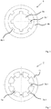
- the Fig. 2 and 3 4 and 5 show possible embodiments for the claw washer 7 and the further claw washer 8.
- the rotatable disk member 7a, 8a is designed as an internal disk component in this embodiment, whereas the stationary disk component 7b, 8b is formed on the outside.
- the disc members 7a, 8a may be fixed and the disc members 7b, 8b may be rotatable (not shown).
- Rotatable and fixed disk component 7a, 7b; 8a, 8b have respective claws 7a.1, 7b.1; 8a.1, 8b.1, which are arranged externally or internally.
- the claws 7a.1, 7b.1; 8a.1, 8b.1 are referred to as teeth or tooth elements.
- a compensation of the cogging torque is achieved in particular in this embodiment by using two mutually offset claw plates 7, 8. If the first is closed, the second is opened. Rotation of the rotor shaft relative to the housing results in closing of the open jaw disc while the closed one is opened.
- the cogging torque results from the lever arm and the reluctance force. The latter is due to the change in the magnetic resistance.
- FIGS. 9 and 10 show axially oppositely magnetized permanent magnets, which are formed as part of the housing 6.
- the oppositely magnetized magnetic elements 9, 10 may also be arranged in the cover 4, 5 or on the rotor shaft 2, which in the FIGS. 9 and 10 is shown.
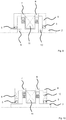
- the claw plate 7 and the further claw plate 8 are arranged on opposite sides of a coil 11 which is designed as a cylindrical coil in the exemplary embodiment shown.
- the coil 11 When running in the Fig. 1 . 6 . 7 and 9 to 12, the coil 11 is accommodated on the housing 6.
- the coil In the Fig. 1 the coil is firmly connected to the housing. This can be useful if the housing 6 is stationary and the rotor shaft 2 is rotated, since the leads can be easily led out.
- the housing to be rotated it may be advantageous to accommodate the coil 11 on the rotor shaft 2, which Fig. 8 shows. Since the housing 2 is located farther out, it usually has a higher moment of inertia than the rotor shaft 2. This can be rotated while the rotor shaft 2 is fixed, therefore, can have advantages if a large amount of energy to be stored in the rotating part or high Requirements for a smooth running exist.
- the respective magnetic flux represented by arrows A1, A2, B1, B2 runs as a function of the rotational position of the claw disc 7 and the further claw disc 8, through the claw disc 7 (cf. Fig. 7 ) and the further claw plate 8 (see. Fig. 6 ).
- the further claw washer 8 this is just the opposite, which is the result of an angular offset of the magnetic flux closing relative positions for the claw washer 7 on the one hand and the other claw washer 8 on the other.
- the magnetic flux is guided here via the bearing device 3.
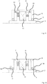
- Fig. 11 shows a schematic representation of an electrodynamic transducer in section, in which magnetic elements by means of electric coils 12, 13 are formed.
- Fig. 12 shows a schematic representation of an electrodynamic transducer in section, in which magnetic elements 3a, 3b of soft magnetic material, the bearing means 3 are provided bridging the magnetic flux.
- the storage device 3 is bridged. This can be useful if the bearings have too high a magnetic resistance or cause eddy currents in the bearing cages to a braking torque.
- Fig. 13 shows a schematic representation of a star-shaped housing cover 20 with coils 21, four of which are shown, for magnetic flux generation for an electrodynamic converter in one of the embodiments explained.
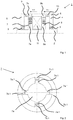
- Fig. 14 shows a perspective view of an electrodynamic transducer.
- Fig. 14 shows a perspective view of an electrodynamic transducer.
- the air gaps between two flux-guiding soft iron components can lie in the different embodiments. These can be manufactured with high precision without increased complexity, whereby the air gap can be set very accurately. This may be another advantage over other concepts in which the permanent magnets co-determine the air gap. These typically have a tolerance of +/- 0.1 mm, which is why the air gap also has large tolerances. This has two adverse effects. On the one hand, the magnetic flux and thus the output power of the generator scatter quite strongly. Also, air gaps deviating from the calculation or over the circumference can disturb the compensation of the cogging torque and thus significantly increase it.
- the magnetic flux from the magnetic elements each selects the path of least magnetic resistance. If a claw disc is closed, almost the entire river runs through it. If the rotor shaft 2 is rotated relative to the housing 6, the two claw disks 7, 8 are offset relative to one another, so that the coil 11 is penetrated by an alternating flow. This leads to the induction of the generator voltage in the coil 11.
- the magnetic flux can also be generated without permanent magnets by two or more coils 12, 13, 21. These can in turn with the housing 6 (see Fig. 11 and 13 ) or the rotor shaft 2 may be connected.
- the electrodynamic transducer it may be useful to wind one or more coils directly on the rotor shaft 2, so as to ensure the manufacturability, without providing a division of the shaft for pushing the coil between the claw plates 7, 8.
- the number and width of the jaws or tooth elements is variable and can be adapted for optimization. Furthermore, the claw shape can be changed by rounding the edges or skew along the longitudinal axis in order to achieve an improved magnetic flux guide at low cogging torques.
- the electrodynamic converter can be used in its various configurations with suitable energization as a motor when at least two units are connected to a shaft or otherwise with each other.
Landscapes
- Engineering & Computer Science (AREA)
- Power Engineering (AREA)
- Reciprocating, Oscillating Or Vibrating Motors (AREA)
- Permanent Field Magnets Of Synchronous Machinery (AREA)
- Electromagnets (AREA)
Description
Die Erfindung betrifft einen elektrodynamischen Wandler.The invention relates to an electrodynamic converter.
Zur Wandlung von mechanischer in elektrische Energie stehen unterschiedliche Generatorprinzipien zur Verfügung. Je nach Baugröße sind die Ausführungsformen der Funktionskomponenten verschiedenartig gestaltet. Bei sehr großen Generatoren werden zur Erzeugung des magnetischen Feldes typischerweise Spulen genutzt, um teure Permanentmagnete zu vermeiden. Die Erzeugung des Magnetfeldes durch einen elektrischen Strom ist jedoch immer mit Verlusten verbunden, die den Wirkungsgrad verschlechtern. Bei kleineren und mittelgroßen Generatoren ist daher der Ensatz von Permanentmagneten üblich. Häufig erfolgt die Energieumwandlung mittels die Umkehrung des Gleichstrom- oder Synchronmotorprinzips, seltener durch die des Asynchronmotors.For the conversion of mechanical into electrical energy different generator principles are available. Depending on the size of the embodiments of the functional components are designed differently. In the case of very large generators, coils are typically used to generate the magnetic field in order to avoid expensive permanent magnets. However, the generation of the magnetic field by an electric current is always associated with losses that deteriorate the efficiency. For smaller and medium-sized generators therefore the use of permanent magnets is common. Frequently, the energy conversion by means of the reversal of the DC or synchronous motor principle, more rarely by the asynchronous motor.
Daneben existieren noch so genannte Transversalflussmaschinen, deren Verbreitung außerhalb der Lichtmaschinen im Automobil jedoch gering ist. Das größte Problem bei Transversalflussmaschinen ist deren Aufbau, der üblicherweise die Fertigung unwirtschaftlich teuer macht. Dies liegt insbesondere an der erforderlichen komplizierten Geometrie der flussführenden Teile. Klauenpolgeneratoren sind eine Sonderbauform der Transversalflussmaschinen. Im Kraftfahrzeugbereich wird der Klauenpolgenerator seit einiger Zeit als Lichtmaschine in großen Stückzahlen genutzt (vgl. zum Beispiel
Ein miniaturisierter Klauenpolgenerator ist im Dokument
Größter Nachteil von üblichen Klauenpolmaschinen ist ihr hohes Rastmoment. Dieses lässt sich zwar durch eine geeignete Gestaltung der Klauen etwas reduzieren. Einer Elimination ist aber bauartbedingt bei allen bisherigen Ausführungsformen eine Grenze gesetzt.The biggest disadvantage of conventional claw-pole machines is their high cogging torque. Although this can be reduced somewhat by a suitable design of the claws. However, an elimination is set by design in all previous embodiments, a limit.
Zur elektrischen Versorgung von kleinen Verbrauchern ist in den letzten Jahren die Nachfrage nach miniaturisierten Generatoren stark angestiegen. Ziel ist es, Geräte autark mit Energie zu versorgen, um neue Funktionen bereitzustellen. Häufig ist dies die Erfassung und drahtlose Weitergabe von Sensordaten. Die benötigten Leistungen sind häufig gering, so dass auch andere Wandlungsprinzipien als elektromagnetische Generatoren erforscht werden, beispielsweise Piezogeneratoren. Deren Leistungsabgabe ist jedoch wesentlich geringer, so dass sie nur für spezielle Anwendungen geeignet sind. Dieses Gebiet wird mit dem englischen Begriff "Energy harvesting" bezeichnet. Mit der zunehmenden Vernetzung von Sensoren im industriellen Umfeld und Verbraucherelektronik jeder Art wird das Interesse an miniaturisierten Generatoren in Zukunft weiter zunehmen.For the electrical supply of small consumers, the demand for miniaturized generators has risen sharply in recent years. The goal is to supply devices with energy autonomously in order to provide new functions. Often this is the capture and wireless transmission of sensor data. The required services are often low, so that other conversion principles are explored as electromagnetic generators, such as piezo generators. However, their power output is much lower, so they are only suitable for specific applications. This area is referred to by the English term " energy harvesting ". With the increasing networking of sensors in the industrial environment and consumer electronics of every kind, interest in miniaturized generators will continue to increase in the future.
Das Dokument
Im Dokument
Das Dokument
Das Dokument
Aufgabe der Erfindung ist es, einen elektrodynamischen Wandler mit verbesserten Betriebseigenschaften zu schaffen.The object of the invention is to provide an electrodynamic transducer with improved operating characteristics.
Diese Aufgabe wird gelöst durch einen elektrodynamischen Wandler nach dem unabhängigen Anspruch 1. Ausgestaltungen sind Gegenstand von abhängigen Unteransprüchen.This object is achieved by an electrodynamic transducer according to
Es ist ein elektrodynamischer Wandler vorgeschlagen. Eine Klauenscheibe ist einer Spule zugeordnet und auf einer Seite der Spule angeordnet. Die Klauenscheibe weist ein um eine Drehachse drehbares Scheibenbauteil und ein relativ hierzu feststehendes Scheibenbauteil auf, wobei das drehbare und das feststehende Scheibenbauteil über einander zugeordnete Klauen verfügen, die beim Drehen des drehbaren Scheibenbauteils für die Klauenscheibe abwechselnd eine magnetflussschließende und eine nicht magnetflussschließende Relativstellung einnehmen. Eine weitere Klauenscheibe ist der Spule zugeordnet und auf einer gegenüberliegenden Seite der Spule angeordnet und weist ein um die Drehachse drehbares Scheibenbauteil und ein relativ hierzu feststehendes Scheibenbauteil auf, wobei das drehbare und das feststehende Scheibenbauteil einander zugeordnete Klauen aufweisen, die beim Drehen des drehbaren Scheibenbauteils für die weitere Klauenscheibe abwechselnd eine magnetflussschließende und eine nicht magnetflussschließende Relativstellung einnehmen. Der elektrodynamische Wandler verfügt über Magnetfluss-Bauelemente, die gegensätzlich magnetisierte Magnetbauelemente und Magnetflusselemente aus weich magnetischem Material aufweisen. Von den Magnetfluss-Bauteilen ist im Betrieb jeweils wenigstens ein Teil einem magnetischem Fluss durch die Klauenscheibe oder einem weiteren magnetischen Fluss durch die weitere Klauenscheibe zugeordnet, die sich beim Drehendes drehbaren Scheibenbauteils der Klauenscheibe und des drehbaren Scheibenbauteils der weiteren Klauenscheibe abwechselnd ausbilden abwechselnd ausbilden. Für die Klauenscheibe und die weitere Klauenscheibe sind die magnetflussschließenden Relativstellungen mit einem Winkelversatz zueinander gebildet, wie auch die nicht magnetflussschließenden Relativstellungen.It is proposed an electrodynamic converter. A claw washer is associated with a spool and disposed on one side of the spool. The claw disc has a disc member rotatable about an axis of rotation and a disc member fixed relative thereto, the rotatable and fixed disc members having mutually associated claws which alternately occupy magnetic flux closing and non-magnetic flux closing relative positions as the rotatable disc claw member is rotated. Another claw washer is associated with the spool and disposed on an opposite side of the spool and has a disc member rotatable about the rotational axis and a disc member fixed relative thereto, the rotatable and stationary disc members having mutually associated claws alternately occupying a magnetic flux closing and a non-magnetic flux closing relative position upon rotation of the rotatable disc member for the further claw disc. The electrodynamic transducer has magnetic flux components that have oppositely magnetized magnetic devices and magnetic flux elements of soft magnetic material. In operation, at least one of the magnetic flux components is at least partially associated with a magnetic flux through the claw disk or another magnetic flux through the further claw disk alternately forming as the rotatable disk member of the claw disk and the rotatable disk member of the further claw disk alternately rotate. For the claw washer and the further claw plate, the magnetic flux-closing relative positions are formed with an angular offset from each other, as well as the non-magnetic flux closing relative positions.
Der elektrodynamische Wandler weist einen einfachen und kostengünstig herzustellenden Aufbau auf. Eine Miniaturisierung des Aufbaus ist ohne weiteres ermöglicht.The electrodynamic converter has a simple and inexpensive to manufacture structure. Miniaturization of the structure is readily possible.
Die Drehachse ist von einem Bauteil bereitgestellt, bei dem es sich zum Beispiel um eine Welle handeln kann, insbesondere eine Rotorwelle. Die drehbaren Scheibenbauteile können sich mit der Welle drehen.The axis of rotation is provided by a component which may, for example, be a shaft, in particular a rotor shaft. The rotatable disc components can rotate with the shaft.
Die drehbaren Scheibenbauteile sind zumindest im Betrieb in ihrer Relativlage zueinander fixiert, so dass ein feststehender Winkelversatz ausgebildet ist. Gleiches gilt für die feststehenden Scheibenbauteile von Klauenscheibe und weiterer Klauenscheibe. Der magnetische Fluss in dem elektrodynamischen Wandler verläuft beim Drehen der drehbaren Scheibenbauteile abwechselnd durch die Klauenscheibe und die weitere Klauenscheibe. Magnetflusselemente können sowohl an dem Magnetflusskreis durch die Klauenscheibe wie auch an dem Magnetflusskreis durch die weitere Klauenscheibe oder auch nur an einem der Magnetflusskreise beteiigt sein.The rotatable disc components are fixed relative to each other at least during operation in their relative position, so that a fixed angular offset is formed. The same applies to the fixed disc components of the claw washer and further claw washer. The magnetic flux in the electrodynamic transducer alternately passes through the claw washer and the other claw washer as the rotatable disc components rotate. Magnetic flux elements may be involved both in the magnetic flux circuit through the claw disk and in the magnetic flux circuit through the further claw disk or else only on one of the magnetic circuit circuits.
Die Klauen werden auch als Zahnelemente oder Zähne bezeichnet, so dass dann eine Zahnelement- oder Zahnscheibe gebildet ist.The claws are also referred to as tooth elements or teeth, so that then a Zahnelement- or toothed disc is formed.
Der elektrodynamische Wandler kann ein Gehäuse aufweisen. Bei dieser Ausgestaltung können die feststehenden Scheibenbauteile am Gehäuse angeordnet sein. Alternativ kann das Gehäuse drehbar gelagert sein. Im Betrieb können sich dann die drehbaren Scheibenbauteile mit dem Gehäuse drehen.The electrodynamic converter may comprise a housing. In this embodiment, the fixed disc components may be arranged on the housing. Alternatively, the housing may be rotatably mounted. In operation, the rotatable disc components can then rotate with the housing.
Die Spule kann drehbar um die Drehachse gelagert sein. Alternativ kann die Spule relativ zur Drehachse fixiert sein, zum Beispiel am Gehäuse.The spool can be rotatably mounted about the axis of rotation. Alternatively, the coil may be fixed relative to the axis of rotation, for example on the housing.
Die gegensätzlich magnetisierten Magnetbauelemente können Permanentmagnete aufweisen. Die Permanentmagnete können im Betrieb in den Magnetflusskreis durch die Klauenscheibe und / oder den weiteren Magnetflusskreis durch die weitere Klauenscheibe einbezogen sein.The oppositely magnetized magnetic components may have permanent magnets. During operation, the permanent magnets may be included in the magnetic flux circuit through the claw disk and / or the further magnetic flux circuit through the further claw disk.
Die gegensätzlich magnetisierten Magnetbauelemente können elektrische Magnete aufweisen. Elektrische Magnete können beispielsweise mittels einer oder mehrere Spulen gebildet sein.The oppositely magnetized magnetic components may have electrical magnets. Electric magnets can be formed for example by means of one or more coils.
Die gegensätzlich magnetisierten Magnetbauelemente können in Bezug auf die Drehachse axial und / oder radial magnetisierte Magnetbauelemente aufweisen. Ist eine Welle vorgesehen, zum Beispiel eine Rotorwelle, können gegensätzlich magnetisierte Magnetbauelemente hieran angeordnet sein, insbesondere auch als Teil der Welle ausgebildet sein.The oppositely magnetized magnetic components may have axially and / or radially magnetized magnetic components with respect to the axis of rotation. If a shaft is provided, for example a rotor shaft, oppositely magnetized magnetic components can be arranged thereon, in particular also be designed as part of the shaft.
Bei dem Gehäuse können ein oder mehrere Gehäuseteile als Magnetflusselemente aus weichmagnetischem Material gebildet sein. Zu dem aus weichmagnetischem Material gebildeten Gehäuseteilen können zum Beispiel ein oder beidseitig angeordnete Deckel gehören. Auch eine Lagerungseinrichtung für eine Welle kann zumindest teilweise aus einem weichmagnetischen Material gebildet sein.In the housing, one or more housing parts may be formed as magnetic flux elements of soft magnetic material. To the housing parts formed from soft magnetic material may include, for example, one or both sides arranged lid. Also, a storage device for a shaft may be at least partially formed of a soft magnetic material.
Die Magnetflusselemente können eine Lagereinrichtung einer die Drehachse bereitstellenden Welle überbrückend und hierdurch magnetflussschließend gebildet sein. Die Magnetflusselemente können als Bauteile um die Lagereinrichtung herum geführt sein, sei es mit einem oder mehreren Spalten oder spaltfrei, um so den Magnetfluss um die Lagereinrichtung herumzuführen.The magnetic flux elements can be bridging a bearing device of a shaft providing the axis of rotation and thereby formed magnetic flux-closing. The magnetic flux elements can be guided around the bearing device as components, be it with one or more gaps or gap-free, so as to guide the magnetic flux around the bearing device.
Die Klauenscheibe und die weitere Klauenscheibe können mehrere magnetflussschließende Relativstellungen aufweisen, zum Beispiel wenigstens vier. Eine Ausführung mit acht magnetflussschließenden Relativstellungen, die beim relativen Verdrehen von drehbaren und feststehenden Scheibenbauteil erreicht werden, kann vorgesehen sein.The claw washer and the further claw disk may have a plurality of magnetic flux-closing relative positions, for example at least four. An embodiment with eight magnetic flux closing relative positions, which are achieved in the relative rotation of rotatable and stationary disc component can be provided.
Klauenanordnungen, die in derselben Ausführung an dem drehbaren Scheibenbauteil der Klauenscheibe und an dem drehbaren Scheibenbauteil der weiteren Klauenscheibe gebildet sind, können mit Winkelversatz zueinander angeordnet sein. Dieselbe Ausführung der Klauenanordnungen kann zumindest hinsichtlich der Anzahl und Formgebung der Klauen gebildet sein. Alternativ kann der mit Winkelversatz zwischen den feststehenden Scheibenbauteilen gebildet sein. Im Betrieb ist die Relativstellung der mit Winkelversatz zueinander angeordneten Scheibenbauteile fixiert.Claw assemblies formed in the same embodiment on the rotatable disc member of the claw disc and on the rotatable disc member of the further claw disc may be angularly offset from each other. The same embodiment of the jaw arrangements can be formed at least with regard to the number and shape of the claws. Alternatively, it may be formed with angular offset between the stationary disc components. In operation, the relative position of the angular offset with each other arranged disc components is fixed.
Bei der Klauenscheibe und / oder bei der weiteren Klauenscheibe können das drehbare Scheibenbauteil als ein innenliegendes Scheibenbauteil und das feststehende Scheibenbauteil als ein außenliegendes Scheibenbauteil gebildet sein. Bei dieser oder anderen Ausführungsformen können sich einander zugeordnete Klauen zumindest in der magnetflussschließenden Relativstellung gegenüberliegen und durch einen Luftspalt getrennt sein.In the claw plate and / or the other claw plate, the rotatable disc member may be formed as an inboard disc member and the stationary disc member as an outboard disc member. In this or other embodiments, mutually associated jaws may oppose each other at least in the magnetic flux closing relative position and be separated by an air gap.
Klauen an dem drehbaren Scheibenbauteil und dem feststehenden Scheibenbauteil können mit kreisbogenabschnittförmigen Klauen gebildet sein. Seitenkanten der Klauen können zueinander parallel verlaufen.Claws on the rotatable disc member and the stationary disc member may be formed with circular arc portion-shaped claws. Side edges of the jaws may be parallel to each other.
In der magnetflussschließenden Relativstellung kann ein Spalt zwischen einander gegenüberliegenden Rändern von zugeordneten Klauen, die an dem drehbaren und dem feststehenden Scheibenbauteil gebildet sind, in radialer Richtung im Wesentlichen gleichbleibend breit gebildet sein.In the magnetic flux-closing relative position, a gap between opposing edges of respective jaws formed on the rotatable and fixed disk members may be formed to be substantially uniformly wide in the radial direction.
Im Folgenden werden weitere Ausführungsbeispiele unter Bezugnahme auf Figuren einer Zeichnung erläutert. Hierbei zeigen:
- Fig. 1
- eine schematische Darstellung eines elektrodynamischen Wandlers im Querschnitt,
- Fig. 2
- eine schematische Darstellung einer Klauenscheibe mit innenliegendem Scheibenbauteil und außenliegendem Scheibenbauteil in einer magnetflussschließenden Relativstellung im Schnitt entlang der Linie A-A in
Fig. 1 , - Fig. 3
- eine schematische Darstellung der Klauenscheibe aus
Fig. 2 in einer nicht magnetflussschließenden Relativstellung im Schnitt entlang der Linie B-B inFig. 1 , - Fig. 4
- eine schematische Darstellung einer anderen Klauenscheibe mit innenliegendem Scheibenbauteil und außenliegendem Scheibenbauteil in einer magnetflussschließenden Relativstellung,
- Fig. 5
- eine schematische Darstellung der Klauenscheibe aus
Fig. 4 in nicht magnetflussschließender Relativstellung, - Fig. 6
- eine schematische Darstellung eines elektrodynamischen Wandlers im Schnitt, bei dem ein magnetischer Fluss durch eine rechtsseitig angeordnete Klauenscheibe verläuft,
- Fig. 7
- eine schematische Darstellung des elektrodynamischen Wandlers aus
Fig. 6 , wobei der magnetische Fluss nun durch eine linksseitig angeordnete Klauenscheibe verläuft, - Fig. 8
- eine schematische Darstellung eines elektrodynamischen Wandlers im Schnitt, bei dem eine Spule auf einer Rotorwelle angeordnet ist,
- Fig. 9
- eine schematische Darstellung eines elektrodynamischen Wandlers im Schnitt, bei dem als Permanentmagnete ausgeführte Magnetelemente als Teil einer Rotorwelle gebildet sind,
- Fig. 10
- eine schematische Darstellung eines elektrodynamischen Wandlers im Schnitt, bei dem als Permanentmagnete ausgeführte Magnetelemente als Teil eines Gehäusedeckels gebildet sind,
- Fig. 11
- eine schematische Darstellung eine elektrodynamischen Wandlers im Schnitt, bei dem Magnetelemente mittels Spulen gebildet sind,
- Fig. 12
- eine schematische Darstellung eines elektrodynamischen Wandlers im Schnitt, bei dem Magnetflusselemente eine Lagerung magnetflusskreisschließend gebildet sind,
- Fig. 13
- eine schematische Darstellung eines sternförmigen Deckels mit Spulen zur Flusserzeugung für einen elektrodynamischen Wandler und
- Fig. 14
- eine perspektivische Darstellung einer Ausführung eines elektrodynamischen Wandlers.
- Fig. 1
- a schematic representation of an electrodynamic transducer in cross section,
- Fig. 2
- a schematic representation of a claw plate with internal disc component and external disc component in a magnetic flux closing relative position in section along the line AA in
Fig. 1 . - Fig. 3
- a schematic representation of the claw disk
Fig. 2 in a non-magnetic flux closing relative position in section along the line BB inFig. 1 . - Fig. 4
- a schematic representation of another claw disc with internal disc component and external disc component in a magnetic flux closing relative position,
- Fig. 5
- a schematic representation of the claw disk
Fig. 4 in non-magnetic flux closing relative position, - Fig. 6
- a schematic representation of an electrodynamic transducer in section, in which a magnetic flux passes through a claw plate arranged on the right side,
- Fig. 7
- a schematic representation of the electrodynamic transducer
Fig. 6 , wherein the magnetic flux now passes through a claw washer arranged on the left side, - Fig. 8
- a schematic representation of an electrodynamic transducer in section, in which a coil is arranged on a rotor shaft,
- Fig. 9
- FIG. 2 a schematic representation of an electrodynamic transducer in section, in which magnetic elements embodied as permanent magnets are formed as part of a rotor shaft, FIG.
- Fig. 10
- FIG. 2 a schematic representation of an electrodynamic transducer in section, in which magnetic elements designed as permanent magnets are formed as part of a housing cover, FIG.
- Fig. 11
- a schematic representation of an electrodynamic transducer in section, in which magnetic elements are formed by means of coils,
- Fig. 12
- a schematic representation of an electrodynamic transducer in section, are formed in the magnetic flux elements storage magnetic flux circuit,
- Fig. 13
- a schematic representation of a star-shaped lid with coils for flow generation for an electrodynamic converter and
- Fig. 14
- a perspective view of an embodiment of an electrodynamic transducer.
Im Gehäuse 6 sind eine Klauenscheibe 7 sowie eine weitere Klauenscheibe 8 aufgenommen. Die Klauenscheibe 7 weist ein drehbares Scheibenbauteil 7a auf, welches an der Rotorwelle 2 angeordnet ist. Ein feststehendes Scheibenbauteil 7b der Klauenscheibe 7 ist am Gehäuse 6 angeordnet. In vergleichbarer Weise weist die weitere Klauenscheibe 8 ein drehbares Scheibenbauteil 8a sowie ein feststehendes Scheibenbauteil 8b auf.In the
Die
Wird im Betrieb mittels Drehen der Rotorwelle 2 das jeweilige drehbare Scheibenbauteil 7a, 8a gedreht und somit in unterschiedliche Relativstellungen zum jeweiligen feststehenden Scheibenbauteil 7b, 8b gebracht, so stellen sich für die Klauenscheibe 7 sowie die weitere Klauenscheibe 8 magnetflussschließende Relativstellungen (Drehstellungen) (vgl.
Die dargestellten Ausführungsformen in den
Im Gehäuse 6 sind die Klauenscheibe 7 sowie die weitere Klauenscheibe 8 auf gegenüberliegenden Seiten einer im gezeigten Ausführungsbeispiel als Zylinderspule ausgeführten Spule 11 angeordnet sind.In the
Bei der Ausführung in den
Bei den Darstellungen in den
Gegenüber bekannten elektrodynamischen Wandlern mit Klauen- oder Zahnelementscheibe ergibt sich ein vereinfachter Aufbau, insbesondere dadurch, dass zum Beispiel zwei durchgängig in eine Richtung axial magnetisierte Magnete verwendet werden, anstatt von Einzelmagneten oder alternierend magnetisierten Magneten. Einzelmagnete sind aufwendiger zu montieren und neigen zum Verrutschen. Alternierend magnetisierte Permanentmagnete sind dagegen aufwendig in der Herstellung. Beides erhöht die Kosten und steht einem kommerziellen Einsatz entgegen. Axial magnetisierte Magnete sind jedoch leicht zu erhalten oder können auch in Sondergrößen vergleichsweise preiswert von verschiedenen Anbietern nach Kundenwunsch geliefert werden.Compared with known electrodynamic transducers with claw or toothed disc element results in a simplified structure, in particular by the fact that, for example, two axially in one direction axially magnetized magnets are used, instead of individual magnets or alternately magnetized magnet. Single magnets are more expensive to assemble and tend to slip. Alternately magnetized permanent magnets, however, are expensive to manufacture. Both increase the costs and preclude commercial use. Axially magnetized magnets, however, are easy to obtain or can be supplied in special sizes comparatively inexpensive by different suppliers according to customer requirements.
Bei dem vorgeschlagenen Aufbau können in den verschiedenen Ausführungen die Luftspalte zwischen zwei flussführenden Weicheisen-Bauteilen liegen. Diese lassen sich ohne erhöhten Aufwand mit hoher Präzision fertigen, wodurch sich der Luftspalt sehr genau einstellen lässt. Hierin kann ein weiterer Vorteil gegenüber anderen Konzepten liegen, bei denen die Permanentmagnete den Luftspalt mitbestimmen. Diese weisen typischerweise eine Toleranz von +/- 0,1 mm auf, weswegen der Luftspalt ebenfalls große Toleranzen besitzt. Dies hat zwei nachteilige Effekte. Einerseits streuen der magnetische Fluss und damit die Ausgangsleistung des Generators recht stark. Auch können von der Berechnung oder über den Umfang abweichende Luftspalte die Kompensation des Rastmoments stören und dieses somit signifikant erhöhen.In the proposed construction, the air gaps between two flux-guiding soft iron components can lie in the different embodiments. These can be manufactured with high precision without increased complexity, whereby the air gap can be set very accurately. This may be another advantage over other concepts in which the permanent magnets co-determine the air gap. These typically have a tolerance of +/- 0.1 mm, which is why the air gap also has large tolerances. This has two adverse effects. On the one hand, the magnetic flux and thus the output power of the generator scatter quite strongly. Also, air gaps deviating from the calculation or over the circumference can disturb the compensation of the cogging torque and thus significantly increase it.
Der magnetische Fluss von den Magnetelementen, sei es in Form der Permanentmagnete oder auf Basis der Spulen, wählt jeweils den Weg des geringsten magnetischen Widerstands. Ist eine Klauenscheibe geschlossen, verläuft fast der gesamte Fluss durch diese. Wird die Rotorwelle 2 gegenüber dem Gehäuse 6 gedreht, so werden zueinander versetzt die beiden Klauenscheiben 7, 8 geschlossen, so dass die Spule 11 von einem wechselnden Fluss durchsetzt wird. Dies führt zur Induktion der Generatorspannung in der Spule 11.The magnetic flux from the magnetic elements, be it in the form of permanent magnets or based on the coils, each selects the path of least magnetic resistance. If a claw disc is closed, almost the entire river runs through it. If the
Der magnetische Fluss kann auch ohne Permanentmagnete durch zwei oder mehr Spulen 12, 13, 21 erzeugt werden. Diese können wiederum mit dem Gehäuse 6 (siehe
Je nach Aufbau des elektrodynamischen Wandlers kann es sinnvoll sein, eine oder mehrere Spulen direkt auf die Rotorwelle 2 zu wickeln, um so die Fertigbarkeit zu gewährleisten, ohne eine Teilung der Welle zum Aufschieben der Spule zwischen die Klauenscheiben 7, 8 vorzusehen.Depending on the structure of the electrodynamic transducer, it may be useful to wind one or more coils directly on the
Die Anzahl und Breite der Klauen oder Zahnelemente ist variabel und lässt sich zur Optimierung anpassen. Weiterhin kann auch die Klauenform durch Abrunden der Kanten oder Schrägung entlang der Längsachse verändert werden, um eine verbesserte Magnetflussführung bei geringen Rastmomenten zu erzielen.The number and width of the jaws or tooth elements is variable and can be adapted for optimization. Furthermore, the claw shape can be changed by rounding the edges or skew along the longitudinal axis in order to achieve an improved magnetic flux guide at low cogging torques.
Der elektrodynamische Wandler kann in seinen verschiedenen Ausgestaltungen bei geeigneter Bestromung auch als Motor verwendet werden, wenn mindestens zwei Einheiten auf einer Welle oder anderweitig miteinander verbunden werden.The electrodynamic converter can be used in its various configurations with suitable energization as a motor when at least two units are connected to a shaft or otherwise with each other.
Die in der vorstehenden Beschreibung, den Ansprüchen sowie der Zeichnung offenbarten Merkmale können sowohl einzeln als auch in beliebiger Kombination für die Verwirklichung der verschiedenen Ausführungen von Bedeutung sein.The features disclosed in the above description, the claims and the drawings may be important both individually and in any combination for the realization of the various embodiments.
Claims (12)
- An electrodynamic transducer (1) comprising- a coil (11),- a claw disc (7) assigned to the coil (11) which is arranged on one side of the coil (11) and which comprises a disc component (7a) which is rotatable about a rotary axis and a disc component (7b) which is stationary in relation thereto, wherein the rotatable and the stationary disc component (7a, 7b) comprise claws assigned to each other, which during rotation of the rotatable disc component (7a) for the claw disc (7) alternate between assuming a magnetic-flux-closing relative position and a not-magnetic-flux-closing relative position,- a further claw disc (8) assigned to the coil (11) which is arranged on an opposite side of the coil (11) and which comprises a disc component (8a) which is rotatable about the rotary axis and a disc component (8b) stationary in relation thereto, wherein the rotatable and the stationary disc component (8a, 8b) comprise claws assigned to each other, which during rotation of the rotatable disc component (8a) for the further claw disc (8) alternate between assuming a magnetic-flux-closing relative position and a not-magnetic-flux-closing relative position, and- magnetic flux construction elements, which comprise axially opposing, oppositely magnetised magnetic construction elements (9, 10; 12, 13) and magnetic flux elements of a magnetically soft material, of which in operation at least a part is assigned to a magnetic flux through the claw disc (7) or to a further magnetic flux through the further claw disc (8), respectively, which alternate in forming during rotation of the rotatable disc component (7a) of the claw disc (7) and during rotation of the rotatable disc component (8a) of the further claw disc (8),wherein the magnetic-flux-closing relative positions for the claw disc (7) and the further claw disc (8), as well as the not-magnetic-flux-closing relative positions, are formed with an angular offset to each other.
- The electrodynamic transducer according to claim 1, characterised in that the oppositely magnetised magnetic construction elements comprise permanent magnets (9, 10).
- The electrodynamic transducer (1) according to claim 1 or 2, characterised in that the oppositely magnetised magnetic construction elements comprise electric magnets (12, 13).
- The electrodynamic transducer (1) according to at least one of the preceding claims, characterised in that the oppositely magnetised magnetic construction elements, relative to the rotary axis, comprise axially and/or radially magnetised magnetic construction elements.
- The electrodynamic transducer (1) according to at least one of the preceding claims, characterised by a housing (6), wherein one or more housing parts of the housing (6) are formed as magnetic flux elements from a magnetically soft material.
- The electrodynamic transducer (1) according to at least one of the preceding claims, characterised in that magnetic flux elements (3a, 3b) are formed bridging a bearing device (3) of a shaft (2) rotating about the rotary axis and, as a result, are formed so as to be magnetic-flux-closing.
- The electrodynamic transducer (1) according to at least one of the preceding claims, characterised in that the claw disc (7) and the further claw disc (8) each comprise multiple magnetic-flux-closing relative positions.
- The electrodynamic transducer (1) according to at least one of the preceding claims, characterised in that claw arrangements of identical design formed on the rotatable disc component (7a) of the claw disc (7) and on the rotatable disc component (8a) of the further claw disc (8) are arranged at an angular offset to each other.
- The electrodynamic transducer (1) according to at least one of the preceding claims, characterised in that with the claw disc (7) and/or with the further claw disc (8) the rotatable disc component (7a; 8a) is formed as an inside disc component and the stationary disc component (7b; 8b) is formed as an outside disc component.
- The electrodynamic transducer according to at least one of the preceding claims, characterised in that claws on the rotatable disc component (7a; 8a) and claws on the stationary disc component (7b; 8b) are formed with claws shaped as circular arc sections.
- The electrodynamic transducer according to at least one of the preceding claims, characterised in that in the magnetic-flux-closing relative position, a gap is formed between opposite edges of associated claws formed on the rotatable and on the stationary disc component (7a; 8a, 7b; 8b), which gap is of substantially consistent width in radial direction.
- The electrodynamic transducer according to at least one of the preceding claims, characterised in that the coil (11) is arranged on a rotor shaft (2) and is rotatable in conjunction therewith.
Applications Claiming Priority (2)
| Application Number | Priority Date | Filing Date | Title |
|---|---|---|---|
| DE102014113648.9A DE102014113648B4 (en) | 2014-09-22 | 2014-09-22 | Electrodynamic transducer |
| PCT/DE2015/100399 WO2016045663A1 (en) | 2014-09-22 | 2015-09-22 | Electrodynamic converter |
Publications (2)
| Publication Number | Publication Date |
|---|---|
| EP3198707A1 EP3198707A1 (en) | 2017-08-02 |
| EP3198707B1 true EP3198707B1 (en) | 2019-07-10 |
Family
ID=54364948
Family Applications (1)
| Application Number | Title | Priority Date | Filing Date |
|---|---|---|---|
| EP15787442.1A Active EP3198707B1 (en) | 2014-09-22 | 2015-09-22 | Electrodynamic transducer |
Country Status (5)
| Country | Link |
|---|---|
| US (1) | US10756608B2 (en) |
| EP (1) | EP3198707B1 (en) |
| CN (1) | CN107112871B (en) |
| DE (1) | DE102014113648B4 (en) |
| WO (1) | WO2016045663A1 (en) |
Citations (3)
| Publication number | Priority date | Publication date | Assignee | Title |
|---|---|---|---|---|
| US2760093A (en) * | 1953-05-07 | 1956-08-21 | Nat Pneumatic Co Inc | Electric generator |
| DE2727450A1 (en) * | 1976-07-05 | 1978-01-12 | Philips Nv | SYNCHRONOUS MOTOR |
| US4127802A (en) * | 1977-04-06 | 1978-11-28 | Johnson Milton H | High torque stepping motor |
Family Cites Families (11)
| Publication number | Priority date | Publication date | Assignee | Title |
|---|---|---|---|---|
| DE165101C (en) * | ||||
| DE3917343C2 (en) | 1989-05-27 | 2002-08-29 | Bosch Gmbh Robert | Claw pole generator without slip ring |
| DE19547159A1 (en) * | 1994-12-21 | 1996-06-27 | Wolfgang Hill | Transverse flux machine with rotor parts within soft magnetic body |
| DE10106519A1 (en) | 2001-02-13 | 2002-08-22 | Bosch Gmbh Robert | Electrical machine |
| DE10217285A1 (en) | 2002-04-12 | 2003-11-06 | Coreta Gmbh | Electromechanical energy converter |
| DE10229198A1 (en) | 2002-06-28 | 2004-01-22 | Robert Bosch Gmbh | Electric machine, especially polyphase generator, has magnetically neutral distance holder arranged between pole fingers of two claw poles to fix fingers relative to each other in peripheral direction |
| US20050006972A1 (en) | 2003-07-07 | 2005-01-13 | Bradfield Michael D. | Twin coil claw pole rotor with segmented stator winding for electrical machine |
| JP2007282420A (en) | 2006-04-10 | 2007-10-25 | Denso Corp | Vehicle ac power generator |
| DE102012001114B4 (en) | 2012-01-23 | 2023-03-30 | Sew-Eurodrive Gmbh & Co Kg | electric machine |
| WO2013153575A1 (en) * | 2012-04-10 | 2013-10-17 | 三菱電機株式会社 | Electric motor |
| AR089679A1 (en) * | 2013-01-04 | 2014-09-10 | Ricardo Rucci Hugo | ELECTRIC MACHINE WITHOUT COLLECTOR, WITH HIGH COEFFICIENT PERFORMANCE |
-
2014
- 2014-09-22 DE DE102014113648.9A patent/DE102014113648B4/en not_active Expired - Fee Related
-
2015
- 2015-09-22 WO PCT/DE2015/100399 patent/WO2016045663A1/en active Application Filing
- 2015-09-22 US US15/513,063 patent/US10756608B2/en active Active
- 2015-09-22 CN CN201580051101.4A patent/CN107112871B/en active Active
- 2015-09-22 EP EP15787442.1A patent/EP3198707B1/en active Active
Patent Citations (3)
| Publication number | Priority date | Publication date | Assignee | Title |
|---|---|---|---|---|
| US2760093A (en) * | 1953-05-07 | 1956-08-21 | Nat Pneumatic Co Inc | Electric generator |
| DE2727450A1 (en) * | 1976-07-05 | 1978-01-12 | Philips Nv | SYNCHRONOUS MOTOR |
| US4127802A (en) * | 1977-04-06 | 1978-11-28 | Johnson Milton H | High torque stepping motor |
Also Published As
| Publication number | Publication date |
|---|---|
| US10756608B2 (en) | 2020-08-25 |
| DE102014113648B4 (en) | 2017-09-21 |
| CN107112871B (en) | 2019-12-13 |
| DE102014113648A1 (en) | 2016-04-07 |
| WO2016045663A1 (en) | 2016-03-31 |
| CN107112871A (en) | 2017-08-29 |
| EP3198707A1 (en) | 2017-08-02 |
| US20170331354A1 (en) | 2017-11-16 |
Similar Documents
| Publication | Publication Date | Title |
|---|---|---|
| DE60204965T2 (en) | BRUSHLESS VERNIEREFFEKTMOTOR | |
| EP0221228B1 (en) | Electric drive | |
| DE112006002546B4 (en) | Electric motor with asymmetric poles | |
| DE112005000091T5 (en) | Electric machine | |
| EP0286905A1 (en) | Electronically commutated brushless DC motor | |
| DE112011100218T5 (en) | Rotating electric machine | |
| DE102010004887A1 (en) | Spool for mounting on a magnetic core, magnetic core for reluctance resolver and method of manufacture | |
| DE102017202925B4 (en) | Rotating electrical machine | |
| EP2770616A1 (en) | Electrical machine with split stator | |
| DE102021102807A1 (en) | Magnets, pole pieces and slot openings of an axial flux motor | |
| DE102004025660A1 (en) | Linear motor structure using permanent magnet, with N-magnet pole width increased at one side of magnetic yoke, with increased distance from stator, with S-magnet pole width increased at one side of S-pole magnetic yoke | |
| DE4310226A1 (en) | Electric motor excited by permanent magnets | |
| DE102017204072A1 (en) | Electric machine | |
| EP0940000B1 (en) | Electronically switched two phases reluctance machine | |
| DE102008062025A1 (en) | Stepper motor device | |
| EP0614263A1 (en) | Single-phase reluctance motor capable of starting in a desired rotational direction | |
| DE102008022209A1 (en) | AC motor | |
| DE112019001628T5 (en) | ENGINE | |
| EP3198707B1 (en) | Electrodynamic transducer | |
| DE102020129142A1 (en) | Rotor for a rotating electrical machine | |
| EP2149963B1 (en) | Magnet spin motor | |
| DE102019004428A1 (en) | Electronically commutated electric motor | |
| WO2009121444A1 (en) | Claw pole motor | |
| DE102016208780B4 (en) | electric motor | |
| DE102016201094A1 (en) | Electric machine |
Legal Events
| Date | Code | Title | Description |
|---|---|---|---|
| STAA | Information on the status of an ep patent application or granted ep patent |
Free format text: STATUS: THE INTERNATIONAL PUBLICATION HAS BEEN MADE |
|
| PUAI | Public reference made under article 153(3) epc to a published international application that has entered the european phase |
Free format text: ORIGINAL CODE: 0009012 |
|
| STAA | Information on the status of an ep patent application or granted ep patent |
Free format text: STATUS: REQUEST FOR EXAMINATION WAS MADE |
|
| 17P | Request for examination filed |
Effective date: 20170405 |
|
| AK | Designated contracting states |
Kind code of ref document: A1 Designated state(s): AL AT BE BG CH CY CZ DE DK EE ES FI FR GB GR HR HU IE IS IT LI LT LU LV MC MK MT NL NO PL PT RO RS SE SI SK SM TR |
|
| AX | Request for extension of the european patent |
Extension state: BA ME |
|
| RIN1 | Information on inventor provided before grant (corrected) |
Inventor name: DREYER, ROBERT Inventor name: KELP, MARTIN Inventor name: MOENNICH, OLIVER |
|
| DAV | Request for validation of the european patent (deleted) | ||
| DAX | Request for extension of the european patent (deleted) | ||
| STAA | Information on the status of an ep patent application or granted ep patent |
Free format text: STATUS: EXAMINATION IS IN PROGRESS |
|
| 17Q | First examination report despatched |
Effective date: 20180518 |
|
| GRAP | Despatch of communication of intention to grant a patent |
Free format text: ORIGINAL CODE: EPIDOSNIGR1 |
|
| STAA | Information on the status of an ep patent application or granted ep patent |
Free format text: STATUS: GRANT OF PATENT IS INTENDED |
|
| INTG | Intention to grant announced |
Effective date: 20190130 |
|
| GRAS | Grant fee paid |
Free format text: ORIGINAL CODE: EPIDOSNIGR3 |
|
| GRAA | (expected) grant |
Free format text: ORIGINAL CODE: 0009210 |
|
| STAA | Information on the status of an ep patent application or granted ep patent |
Free format text: STATUS: THE PATENT HAS BEEN GRANTED |
|
| AK | Designated contracting states |
Kind code of ref document: B1 Designated state(s): AL AT BE BG CH CY CZ DE DK EE ES FI FR GB GR HR HU IE IS IT LI LT LU LV MC MK MT NL NO PL PT RO RS SE SI SK SM TR |
|
| REG | Reference to a national code |
Ref country code: GB Ref legal event code: FG4D Free format text: NOT ENGLISH |
|
| REG | Reference to a national code |
Ref country code: CH Ref legal event code: EP Ref country code: AT Ref legal event code: REF Ref document number: 1154544 Country of ref document: AT Kind code of ref document: T Effective date: 20190715 |
|
| REG | Reference to a national code |
Ref country code: DE Ref legal event code: R096 Ref document number: 502015009628 Country of ref document: DE |
|
| REG | Reference to a national code |
Ref country code: IE Ref legal event code: FG4D Free format text: LANGUAGE OF EP DOCUMENT: GERMAN |
|
| REG | Reference to a national code |
Ref country code: NL Ref legal event code: MP Effective date: 20190710 |
|
| REG | Reference to a national code |
Ref country code: LT Ref legal event code: MG4D |
|
| PG25 | Lapsed in a contracting state [announced via postgrant information from national office to epo] |
Ref country code: LT Free format text: LAPSE BECAUSE OF FAILURE TO SUBMIT A TRANSLATION OF THE DESCRIPTION OR TO PAY THE FEE WITHIN THE PRESCRIBED TIME-LIMIT Effective date: 20190710 Ref country code: HR Free format text: LAPSE BECAUSE OF FAILURE TO SUBMIT A TRANSLATION OF THE DESCRIPTION OR TO PAY THE FEE WITHIN THE PRESCRIBED TIME-LIMIT Effective date: 20190710 Ref country code: PT Free format text: LAPSE BECAUSE OF FAILURE TO SUBMIT A TRANSLATION OF THE DESCRIPTION OR TO PAY THE FEE WITHIN THE PRESCRIBED TIME-LIMIT Effective date: 20191111 Ref country code: NL Free format text: LAPSE BECAUSE OF FAILURE TO SUBMIT A TRANSLATION OF THE DESCRIPTION OR TO PAY THE FEE WITHIN THE PRESCRIBED TIME-LIMIT Effective date: 20190710 Ref country code: NO Free format text: LAPSE BECAUSE OF FAILURE TO SUBMIT A TRANSLATION OF THE DESCRIPTION OR TO PAY THE FEE WITHIN THE PRESCRIBED TIME-LIMIT Effective date: 20191010 Ref country code: SE Free format text: LAPSE BECAUSE OF FAILURE TO SUBMIT A TRANSLATION OF THE DESCRIPTION OR TO PAY THE FEE WITHIN THE PRESCRIBED TIME-LIMIT Effective date: 20190710 Ref country code: BG Free format text: LAPSE BECAUSE OF FAILURE TO SUBMIT A TRANSLATION OF THE DESCRIPTION OR TO PAY THE FEE WITHIN THE PRESCRIBED TIME-LIMIT Effective date: 20191010 Ref country code: FI Free format text: LAPSE BECAUSE OF FAILURE TO SUBMIT A TRANSLATION OF THE DESCRIPTION OR TO PAY THE FEE WITHIN THE PRESCRIBED TIME-LIMIT Effective date: 20190710 |
|
| PG25 | Lapsed in a contracting state [announced via postgrant information from national office to epo] |
Ref country code: IS Free format text: LAPSE BECAUSE OF FAILURE TO SUBMIT A TRANSLATION OF THE DESCRIPTION OR TO PAY THE FEE WITHIN THE PRESCRIBED TIME-LIMIT Effective date: 20191110 Ref country code: GR Free format text: LAPSE BECAUSE OF FAILURE TO SUBMIT A TRANSLATION OF THE DESCRIPTION OR TO PAY THE FEE WITHIN THE PRESCRIBED TIME-LIMIT Effective date: 20191011 Ref country code: ES Free format text: LAPSE BECAUSE OF FAILURE TO SUBMIT A TRANSLATION OF THE DESCRIPTION OR TO PAY THE FEE WITHIN THE PRESCRIBED TIME-LIMIT Effective date: 20190710 Ref country code: RS Free format text: LAPSE BECAUSE OF FAILURE TO SUBMIT A TRANSLATION OF THE DESCRIPTION OR TO PAY THE FEE WITHIN THE PRESCRIBED TIME-LIMIT Effective date: 20190710 Ref country code: AL Free format text: LAPSE BECAUSE OF FAILURE TO SUBMIT A TRANSLATION OF THE DESCRIPTION OR TO PAY THE FEE WITHIN THE PRESCRIBED TIME-LIMIT Effective date: 20190710 Ref country code: LV Free format text: LAPSE BECAUSE OF FAILURE TO SUBMIT A TRANSLATION OF THE DESCRIPTION OR TO PAY THE FEE WITHIN THE PRESCRIBED TIME-LIMIT Effective date: 20190710 |
|
| PG25 | Lapsed in a contracting state [announced via postgrant information from national office to epo] |
Ref country code: TR Free format text: LAPSE BECAUSE OF FAILURE TO SUBMIT A TRANSLATION OF THE DESCRIPTION OR TO PAY THE FEE WITHIN THE PRESCRIBED TIME-LIMIT Effective date: 20190710 |
|
| PG25 | Lapsed in a contracting state [announced via postgrant information from national office to epo] |
Ref country code: EE Free format text: LAPSE BECAUSE OF FAILURE TO SUBMIT A TRANSLATION OF THE DESCRIPTION OR TO PAY THE FEE WITHIN THE PRESCRIBED TIME-LIMIT Effective date: 20190710 Ref country code: PL Free format text: LAPSE BECAUSE OF FAILURE TO SUBMIT A TRANSLATION OF THE DESCRIPTION OR TO PAY THE FEE WITHIN THE PRESCRIBED TIME-LIMIT Effective date: 20190710 Ref country code: RO Free format text: LAPSE BECAUSE OF FAILURE TO SUBMIT A TRANSLATION OF THE DESCRIPTION OR TO PAY THE FEE WITHIN THE PRESCRIBED TIME-LIMIT Effective date: 20190710 Ref country code: IT Free format text: LAPSE BECAUSE OF FAILURE TO SUBMIT A TRANSLATION OF THE DESCRIPTION OR TO PAY THE FEE WITHIN THE PRESCRIBED TIME-LIMIT Effective date: 20190710 Ref country code: DK Free format text: LAPSE BECAUSE OF FAILURE TO SUBMIT A TRANSLATION OF THE DESCRIPTION OR TO PAY THE FEE WITHIN THE PRESCRIBED TIME-LIMIT Effective date: 20190710 |
|
| PG25 | Lapsed in a contracting state [announced via postgrant information from national office to epo] |
Ref country code: SK Free format text: LAPSE BECAUSE OF FAILURE TO SUBMIT A TRANSLATION OF THE DESCRIPTION OR TO PAY THE FEE WITHIN THE PRESCRIBED TIME-LIMIT Effective date: 20190710 Ref country code: IS Free format text: LAPSE BECAUSE OF FAILURE TO SUBMIT A TRANSLATION OF THE DESCRIPTION OR TO PAY THE FEE WITHIN THE PRESCRIBED TIME-LIMIT Effective date: 20200224 Ref country code: MC Free format text: LAPSE BECAUSE OF FAILURE TO SUBMIT A TRANSLATION OF THE DESCRIPTION OR TO PAY THE FEE WITHIN THE PRESCRIBED TIME-LIMIT Effective date: 20190710 Ref country code: SM Free format text: LAPSE BECAUSE OF FAILURE TO SUBMIT A TRANSLATION OF THE DESCRIPTION OR TO PAY THE FEE WITHIN THE PRESCRIBED TIME-LIMIT Effective date: 20190710 Ref country code: CZ Free format text: LAPSE BECAUSE OF FAILURE TO SUBMIT A TRANSLATION OF THE DESCRIPTION OR TO PAY THE FEE WITHIN THE PRESCRIBED TIME-LIMIT Effective date: 20190710 |
|
| REG | Reference to a national code |
Ref country code: DE Ref legal event code: R097 Ref document number: 502015009628 Country of ref document: DE |
|
| PLBE | No opposition filed within time limit |
Free format text: ORIGINAL CODE: 0009261 |
|
| STAA | Information on the status of an ep patent application or granted ep patent |
Free format text: STATUS: NO OPPOSITION FILED WITHIN TIME LIMIT |
|
| PG2D | Information on lapse in contracting state deleted |
Ref country code: IS |
|
| PG25 | Lapsed in a contracting state [announced via postgrant information from national office to epo] |
Ref country code: IE Free format text: LAPSE BECAUSE OF NON-PAYMENT OF DUE FEES Effective date: 20190922 Ref country code: LU Free format text: LAPSE BECAUSE OF NON-PAYMENT OF DUE FEES Effective date: 20190922 |
|
| 26N | No opposition filed |
Effective date: 20200603 |
|
| REG | Reference to a national code |
Ref country code: BE Ref legal event code: MM Effective date: 20190930 |
|
| PG25 | Lapsed in a contracting state [announced via postgrant information from national office to epo] |
Ref country code: SI Free format text: LAPSE BECAUSE OF FAILURE TO SUBMIT A TRANSLATION OF THE DESCRIPTION OR TO PAY THE FEE WITHIN THE PRESCRIBED TIME-LIMIT Effective date: 20190710 Ref country code: BE Free format text: LAPSE BECAUSE OF NON-PAYMENT OF DUE FEES Effective date: 20190930 |
|
| PG25 | Lapsed in a contracting state [announced via postgrant information from national office to epo] |
Ref country code: CY Free format text: LAPSE BECAUSE OF FAILURE TO SUBMIT A TRANSLATION OF THE DESCRIPTION OR TO PAY THE FEE WITHIN THE PRESCRIBED TIME-LIMIT Effective date: 20190710 |
|
| PG25 | Lapsed in a contracting state [announced via postgrant information from national office to epo] |
Ref country code: HU Free format text: LAPSE BECAUSE OF FAILURE TO SUBMIT A TRANSLATION OF THE DESCRIPTION OR TO PAY THE FEE WITHIN THE PRESCRIBED TIME-LIMIT; INVALID AB INITIO Effective date: 20150922 Ref country code: MT Free format text: LAPSE BECAUSE OF FAILURE TO SUBMIT A TRANSLATION OF THE DESCRIPTION OR TO PAY THE FEE WITHIN THE PRESCRIBED TIME-LIMIT Effective date: 20190710 |
|
| PG25 | Lapsed in a contracting state [announced via postgrant information from national office to epo] |
Ref country code: MK Free format text: LAPSE BECAUSE OF FAILURE TO SUBMIT A TRANSLATION OF THE DESCRIPTION OR TO PAY THE FEE WITHIN THE PRESCRIBED TIME-LIMIT Effective date: 20190710 |
|
| PGFP | Annual fee paid to national office [announced via postgrant information from national office to epo] |
Ref country code: GB Payment date: 20230921 Year of fee payment: 9 Ref country code: AT Payment date: 20230915 Year of fee payment: 9 |
|
| PGFP | Annual fee paid to national office [announced via postgrant information from national office to epo] |
Ref country code: FR Payment date: 20230918 Year of fee payment: 9 Ref country code: DE Payment date: 20230919 Year of fee payment: 9 |
|
| PGFP | Annual fee paid to national office [announced via postgrant information from national office to epo] |
Ref country code: CH Payment date: 20231001 Year of fee payment: 9 |