EP3198668B1 - Verfahren zur beschichtung von trennfolien von lithiumbatterien und beschichtete separatorfolie - Google Patents
Verfahren zur beschichtung von trennfolien von lithiumbatterien und beschichtete separatorfolie Download PDFInfo
- Publication number
- EP3198668B1 EP3198668B1 EP15845097.3A EP15845097A EP3198668B1 EP 3198668 B1 EP3198668 B1 EP 3198668B1 EP 15845097 A EP15845097 A EP 15845097A EP 3198668 B1 EP3198668 B1 EP 3198668B1
- Authority
- EP
- European Patent Office
- Prior art keywords
- coating
- polymer film
- inorganic
- porous
- porosity
- Prior art date
- Legal status (The legal status is an assumption and is not a legal conclusion. Google has not performed a legal analysis and makes no representation as to the accuracy of the status listed.)
- Active
Links
Images

Classifications
-
- H—ELECTRICITY
- H01—ELECTRIC ELEMENTS
- H01M—PROCESSES OR MEANS, e.g. BATTERIES, FOR THE DIRECT CONVERSION OF CHEMICAL ENERGY INTO ELECTRICAL ENERGY
- H01M10/00—Secondary cells; Manufacture thereof
- H01M10/05—Accumulators with non-aqueous electrolyte
- H01M10/052—Li-accumulators
-
- H—ELECTRICITY
- H01—ELECTRIC ELEMENTS
- H01M—PROCESSES OR MEANS, e.g. BATTERIES, FOR THE DIRECT CONVERSION OF CHEMICAL ENERGY INTO ELECTRICAL ENERGY
- H01M50/00—Constructional details or processes of manufacture of the non-active parts of electrochemical cells other than fuel cells, e.g. hybrid cells
- H01M50/40—Separators; Membranes; Diaphragms; Spacing elements inside cells
- H01M50/403—Manufacturing processes of separators, membranes or diaphragms
-
- C—CHEMISTRY; METALLURGY
- C23—COATING METALLIC MATERIAL; COATING MATERIAL WITH METALLIC MATERIAL; CHEMICAL SURFACE TREATMENT; DIFFUSION TREATMENT OF METALLIC MATERIAL; COATING BY VACUUM EVAPORATION, BY SPUTTERING, BY ION IMPLANTATION OR BY CHEMICAL VAPOUR DEPOSITION, IN GENERAL; INHIBITING CORROSION OF METALLIC MATERIAL OR INCRUSTATION IN GENERAL
- C23C—COATING METALLIC MATERIAL; COATING MATERIAL WITH METALLIC MATERIAL; SURFACE TREATMENT OF METALLIC MATERIAL BY DIFFUSION INTO THE SURFACE, BY CHEMICAL CONVERSION OR SUBSTITUTION; COATING BY VACUUM EVAPORATION, BY SPUTTERING, BY ION IMPLANTATION OR BY CHEMICAL VAPOUR DEPOSITION, IN GENERAL
- C23C14/00—Coating by vacuum evaporation, by sputtering or by ion implantation of the coating forming material
- C23C14/22—Coating by vacuum evaporation, by sputtering or by ion implantation of the coating forming material characterised by the process of coating
- C23C14/24—Vacuum evaporation
- C23C14/28—Vacuum evaporation by wave energy or particle radiation
-
- C—CHEMISTRY; METALLURGY
- C23—COATING METALLIC MATERIAL; COATING MATERIAL WITH METALLIC MATERIAL; CHEMICAL SURFACE TREATMENT; DIFFUSION TREATMENT OF METALLIC MATERIAL; COATING BY VACUUM EVAPORATION, BY SPUTTERING, BY ION IMPLANTATION OR BY CHEMICAL VAPOUR DEPOSITION, IN GENERAL; INHIBITING CORROSION OF METALLIC MATERIAL OR INCRUSTATION IN GENERAL
- C23C—COATING METALLIC MATERIAL; COATING MATERIAL WITH METALLIC MATERIAL; SURFACE TREATMENT OF METALLIC MATERIAL BY DIFFUSION INTO THE SURFACE, BY CHEMICAL CONVERSION OR SUBSTITUTION; COATING BY VACUUM EVAPORATION, BY SPUTTERING, BY ION IMPLANTATION OR BY CHEMICAL VAPOUR DEPOSITION, IN GENERAL
- C23C14/00—Coating by vacuum evaporation, by sputtering or by ion implantation of the coating forming material
- C23C14/06—Coating by vacuum evaporation, by sputtering or by ion implantation of the coating forming material characterised by the coating material
- C23C14/08—Oxides
- C23C14/081—Oxides of aluminium, magnesium or beryllium
-
- C—CHEMISTRY; METALLURGY
- C23—COATING METALLIC MATERIAL; COATING MATERIAL WITH METALLIC MATERIAL; CHEMICAL SURFACE TREATMENT; DIFFUSION TREATMENT OF METALLIC MATERIAL; COATING BY VACUUM EVAPORATION, BY SPUTTERING, BY ION IMPLANTATION OR BY CHEMICAL VAPOUR DEPOSITION, IN GENERAL; INHIBITING CORROSION OF METALLIC MATERIAL OR INCRUSTATION IN GENERAL
- C23C—COATING METALLIC MATERIAL; COATING MATERIAL WITH METALLIC MATERIAL; SURFACE TREATMENT OF METALLIC MATERIAL BY DIFFUSION INTO THE SURFACE, BY CHEMICAL CONVERSION OR SUBSTITUTION; COATING BY VACUUM EVAPORATION, BY SPUTTERING, BY ION IMPLANTATION OR BY CHEMICAL VAPOUR DEPOSITION, IN GENERAL
- C23C14/00—Coating by vacuum evaporation, by sputtering or by ion implantation of the coating forming material
- C23C14/06—Coating by vacuum evaporation, by sputtering or by ion implantation of the coating forming material characterised by the coating material
- C23C14/10—Glass or silica
-
- C—CHEMISTRY; METALLURGY
- C23—COATING METALLIC MATERIAL; COATING MATERIAL WITH METALLIC MATERIAL; CHEMICAL SURFACE TREATMENT; DIFFUSION TREATMENT OF METALLIC MATERIAL; COATING BY VACUUM EVAPORATION, BY SPUTTERING, BY ION IMPLANTATION OR BY CHEMICAL VAPOUR DEPOSITION, IN GENERAL; INHIBITING CORROSION OF METALLIC MATERIAL OR INCRUSTATION IN GENERAL
- C23C—COATING METALLIC MATERIAL; COATING MATERIAL WITH METALLIC MATERIAL; SURFACE TREATMENT OF METALLIC MATERIAL BY DIFFUSION INTO THE SURFACE, BY CHEMICAL CONVERSION OR SUBSTITUTION; COATING BY VACUUM EVAPORATION, BY SPUTTERING, BY ION IMPLANTATION OR BY CHEMICAL VAPOUR DEPOSITION, IN GENERAL
- C23C14/00—Coating by vacuum evaporation, by sputtering or by ion implantation of the coating forming material
- C23C14/22—Coating by vacuum evaporation, by sputtering or by ion implantation of the coating forming material characterised by the process of coating
- C23C14/24—Vacuum evaporation
-
- C—CHEMISTRY; METALLURGY
- C23—COATING METALLIC MATERIAL; COATING MATERIAL WITH METALLIC MATERIAL; CHEMICAL SURFACE TREATMENT; DIFFUSION TREATMENT OF METALLIC MATERIAL; COATING BY VACUUM EVAPORATION, BY SPUTTERING, BY ION IMPLANTATION OR BY CHEMICAL VAPOUR DEPOSITION, IN GENERAL; INHIBITING CORROSION OF METALLIC MATERIAL OR INCRUSTATION IN GENERAL
- C23C—COATING METALLIC MATERIAL; COATING MATERIAL WITH METALLIC MATERIAL; SURFACE TREATMENT OF METALLIC MATERIAL BY DIFFUSION INTO THE SURFACE, BY CHEMICAL CONVERSION OR SUBSTITUTION; COATING BY VACUUM EVAPORATION, BY SPUTTERING, BY ION IMPLANTATION OR BY CHEMICAL VAPOUR DEPOSITION, IN GENERAL
- C23C14/00—Coating by vacuum evaporation, by sputtering or by ion implantation of the coating forming material
- C23C14/22—Coating by vacuum evaporation, by sputtering or by ion implantation of the coating forming material characterised by the process of coating
- C23C14/34—Sputtering
- C23C14/3485—Sputtering using pulsed power to the target
-
- C—CHEMISTRY; METALLURGY
- C23—COATING METALLIC MATERIAL; COATING MATERIAL WITH METALLIC MATERIAL; CHEMICAL SURFACE TREATMENT; DIFFUSION TREATMENT OF METALLIC MATERIAL; COATING BY VACUUM EVAPORATION, BY SPUTTERING, BY ION IMPLANTATION OR BY CHEMICAL VAPOUR DEPOSITION, IN GENERAL; INHIBITING CORROSION OF METALLIC MATERIAL OR INCRUSTATION IN GENERAL
- C23C—COATING METALLIC MATERIAL; COATING MATERIAL WITH METALLIC MATERIAL; SURFACE TREATMENT OF METALLIC MATERIAL BY DIFFUSION INTO THE SURFACE, BY CHEMICAL CONVERSION OR SUBSTITUTION; COATING BY VACUUM EVAPORATION, BY SPUTTERING, BY ION IMPLANTATION OR BY CHEMICAL VAPOUR DEPOSITION, IN GENERAL
- C23C14/00—Coating by vacuum evaporation, by sputtering or by ion implantation of the coating forming material
- C23C14/22—Coating by vacuum evaporation, by sputtering or by ion implantation of the coating forming material characterised by the process of coating
- C23C14/56—Apparatus specially adapted for continuous coating; Arrangements for maintaining the vacuum, e.g. vacuum locks
- C23C14/562—Apparatus specially adapted for continuous coating; Arrangements for maintaining the vacuum, e.g. vacuum locks for coating elongated substrates
-
- H—ELECTRICITY
- H01—ELECTRIC ELEMENTS
- H01M—PROCESSES OR MEANS, e.g. BATTERIES, FOR THE DIRECT CONVERSION OF CHEMICAL ENERGY INTO ELECTRICAL ENERGY
- H01M10/00—Secondary cells; Manufacture thereof
- H01M10/05—Accumulators with non-aqueous electrolyte
- H01M10/058—Construction or manufacture
-
- H—ELECTRICITY
- H01—ELECTRIC ELEMENTS
- H01M—PROCESSES OR MEANS, e.g. BATTERIES, FOR THE DIRECT CONVERSION OF CHEMICAL ENERGY INTO ELECTRICAL ENERGY
- H01M50/00—Constructional details or processes of manufacture of the non-active parts of electrochemical cells other than fuel cells, e.g. hybrid cells
- H01M50/40—Separators; Membranes; Diaphragms; Spacing elements inside cells
- H01M50/409—Separators, membranes or diaphragms characterised by the material
- H01M50/431—Inorganic material
- H01M50/434—Ceramics
-
- H—ELECTRICITY
- H01—ELECTRIC ELEMENTS
- H01M—PROCESSES OR MEANS, e.g. BATTERIES, FOR THE DIRECT CONVERSION OF CHEMICAL ENERGY INTO ELECTRICAL ENERGY
- H01M50/00—Constructional details or processes of manufacture of the non-active parts of electrochemical cells other than fuel cells, e.g. hybrid cells
- H01M50/40—Separators; Membranes; Diaphragms; Spacing elements inside cells
- H01M50/409—Separators, membranes or diaphragms characterised by the material
- H01M50/449—Separators, membranes or diaphragms characterised by the material having a layered structure
- H01M50/451—Separators, membranes or diaphragms characterised by the material having a layered structure comprising layers of only organic material and layers containing inorganic material
-
- H—ELECTRICITY
- H01—ELECTRIC ELEMENTS
- H01M—PROCESSES OR MEANS, e.g. BATTERIES, FOR THE DIRECT CONVERSION OF CHEMICAL ENERGY INTO ELECTRICAL ENERGY
- H01M50/00—Constructional details or processes of manufacture of the non-active parts of electrochemical cells other than fuel cells, e.g. hybrid cells
- H01M50/40—Separators; Membranes; Diaphragms; Spacing elements inside cells
- H01M50/409—Separators, membranes or diaphragms characterised by the material
- H01M50/449—Separators, membranes or diaphragms characterised by the material having a layered structure
- H01M50/457—Separators, membranes or diaphragms characterised by the material having a layered structure comprising three or more layers
-
- H—ELECTRICITY
- H01—ELECTRIC ELEMENTS
- H01M—PROCESSES OR MEANS, e.g. BATTERIES, FOR THE DIRECT CONVERSION OF CHEMICAL ENERGY INTO ELECTRICAL ENERGY
- H01M50/00—Constructional details or processes of manufacture of the non-active parts of electrochemical cells other than fuel cells, e.g. hybrid cells
- H01M50/40—Separators; Membranes; Diaphragms; Spacing elements inside cells
- H01M50/489—Separators, membranes, diaphragms or spacing elements inside the cells, characterised by their physical properties, e.g. swelling degree, hydrophilicity or shut down properties
- H01M50/491—Porosity
-
- Y—GENERAL TAGGING OF NEW TECHNOLOGICAL DEVELOPMENTS; GENERAL TAGGING OF CROSS-SECTIONAL TECHNOLOGIES SPANNING OVER SEVERAL SECTIONS OF THE IPC; TECHNICAL SUBJECTS COVERED BY FORMER USPC CROSS-REFERENCE ART COLLECTIONS [XRACs] AND DIGESTS
- Y02—TECHNOLOGIES OR APPLICATIONS FOR MITIGATION OR ADAPTATION AGAINST CLIMATE CHANGE
- Y02E—REDUCTION OF GREENHOUSE GAS [GHG] EMISSIONS, RELATED TO ENERGY GENERATION, TRANSMISSION OR DISTRIBUTION
- Y02E60/00—Enabling technologies; Technologies with a potential or indirect contribution to GHG emissions mitigation
- Y02E60/10—Energy storage using batteries
-
- Y—GENERAL TAGGING OF NEW TECHNOLOGICAL DEVELOPMENTS; GENERAL TAGGING OF CROSS-SECTIONAL TECHNOLOGIES SPANNING OVER SEVERAL SECTIONS OF THE IPC; TECHNICAL SUBJECTS COVERED BY FORMER USPC CROSS-REFERENCE ART COLLECTIONS [XRACs] AND DIGESTS
- Y02—TECHNOLOGIES OR APPLICATIONS FOR MITIGATION OR ADAPTATION AGAINST CLIMATE CHANGE
- Y02P—CLIMATE CHANGE MITIGATION TECHNOLOGIES IN THE PRODUCTION OR PROCESSING OF GOODS
- Y02P70/00—Climate change mitigation technologies in the production process for final industrial or consumer products
- Y02P70/50—Manufacturing or production processes characterised by the final manufactured product
Definitions
- the invention relates especially to lithium batteries, and to a separator film belonging to their structure.
- the invention further relates to the coating of the said separator films by using a so-called laser ablation method.
- Lithium batteries have done well in very many applications, especially due to good energy density and recharging possibilities, compared e.g. to traditional Ni-Cd and Ni-Mn batteries.
- the lithium battery technology is based on a positive cathode, in which the active material is, for example, transition metal oxide, and on a carbon-based negative anode.
- Microporous polymer separator is used between the anode and cathode to prevent the contact of the anode and cathode, but nevertheless allowing the movement of ions through the separator film.
- the separator film also has to have good mechanical strength and long-term resistance against heat and chemicals.
- a problem with the use of polymer-based microporous films is their temperature resistance, which may be limited to below 150°, in which case a high temperature can cause a short circuit and the electrolyte to flare up and generate a fire in problem situations.
- Safety is important in all operating conditions, including abnormal conditions, such as crashes. It is also in this case important to try to keep the reliability of the operation of batteries as good as possible.
- shrinking of polymeric films during the use e.g. as the temperature rises, chemical stability and the ability of the films to bind liquid electrolyte may restrict the use of polymer membranes. It has been tried to improve the characteristics of polymer films with many different methods, examples of which are disclosed next.
- the characteristics of a separator film can be boosted by coating the surface of the electrode with a combination of polymer and inorganic material, i.e. micro composite material.
- the manufacture is carried out by mixing an inorganic filler with polymer and solvent, by coating an electrode with this solution and by letting the solvent to exit so that a microporous mixture of polymer and inorganic material is obtained. Because the separator is not entirely made of inorganic material, its insulating capacity does not necessarily correspond to a uniform layer of inorganic material.
- CN 103137930 discloses polymer separator membrane surface modification by organic polymer layer prepared by a physical vapor deposition (PVD) method. Furthermore, it comprises preferably a solid electrolyte layer on the polymer separator membrane where the solid electrolyte layer is prepared by a PVD method as well. It also discusses a continuous R2R (roll-to-roll) manufacturing method, vacuum chambers, and pretreatment means. Pulsed laser deposition (i.e. PLD) has been listed as one applicable method among various PVD methods, for coating with an organic polymer layer on the surface of the substrate. However, the resulting coating is dense.
- PLD physical vapor deposition
- US 2012/040233 discusses diffusion barriers, i.e. layers preventing the migration of ionic species or gases, in thin film lithium batteries.
- US 2013/273407 discloses an electrochemical cell where both the anode and the cathode comprise a conductive layer and an active layer applied to the conductive layer. Furthermore, there is a heat-resistant coating on an active layer, the coating comprising a ceramic material. The heat-resistant coating may be porous. Pulsed laser deposition (PLD) is not used in this method for manufacturing an electrochemical cell.
- PLD Pulsed laser deposition
- US 6,110,291 discloses a thin film forming apparatus using a laser source, a plurality of targets, a chamber having evacuating means, and where targets may be rotated. This is a general arrangement applying PLD, with various different alignment angles and placements between the laser source, the targets and the substrate.
- US 2014/217992 discloses coating separator films of Li-ion batteries with metal oxides and sulphur compounds. This results in a Li-S type of battery.
- PLD is listed as one possible option among a group of various manufacturing techniques. The main purpose is to create a coating for Li-S batteries, where complex oxides comprising lithium and vanadium pentoxide are used for decreasing or at least slowing down electrochemical harmful reactions in the battery. Thus, doping material is used in the coating, which is not suitable for general Li-ion batteries and their operability.
- US 2004/0106037 discloses a lithium battery comprising a separator film. It is an inorganic protective film which may be formed by several different available methods, among which laser ablation is mentioned as one. It does not involve the porousness of the inorganic protective film (the coating). Indeed, only the separator film as such is mentioned as porous.
- US 2012/154982 is about a capacitor, and its manufacturing method. It discloses a formation of aluminum layer onto a resin surface in the following way (see par. 0068-0071, in the gas phase method): "In the laser ablation method, for example, Al is molten and vaporized by irradiation with a laser to deposit the Al onto the resin surface of the resin body 1f having the continuous pores, whereby the AI layer 2 can be formed.” (end of par. 0071). So the Al layer is dense, but locating on a porous layer of resin. Furthermore, the reference mentions "ablation" in par. 0091, where "an electrode 12 may be formed by a gas phase method wherein the AI porous body 11 is used as a substrate in an Ar atmosphere.
- the gas phase method may be ... a laser ablation method .
- a solid electrolyte layer 30 can be made by laser ablation, but also "pressing a powder of a solid electrolyte to be hardened” is mentioned in the next sentence.
- Fig. 1b of D13 "11" is aluminum porous body, and "12" is electrode material in a film-form.
- layer 12 can be manufactured on top of 11 by laser ablation in the final (5th and 6th) references of the "laser ablation” in the description of this reference. It is notable that the aluminum structure forms large "pores" in this reference (Figs. 1b-c).
- US 2012/154982 does not build a porous coating on top of another porous material by PLD, where certain PLD parameters are specified, and the result would be a separator film in batteries. Also US 2012/154982 is about capacitors. It applies laser ablation in many steps there, but not in any sense of manufacturing a separator film with a porous coating.
- the present invention discloses a method for coating a porous polymer film for use as a separator film in Li batteries with a porous coating.
- the method comprises the following steps. First laser pulses of a duration of 0,5 - 1000 ps are applied to the target. As a consequence, inorganic material is detached from the target (e.g. as atoms and particles) by laser ablation. After this in the method, detached inorganic material is directed to at least one surface or part of the surface of the polymer film, as a consequence of which a porous coating is produced on at least one surface or part of the surface of the polymer film, as the inorganic material attaches to the said surface of the polymer film. Then, the porosity of the inorganic coating is principally thorough, which makes possible that an electrolyte moistens the polymer film. Finally, the porosity of the inorganic porous coating is between 20 - 70 volumetric percentages.
- the thickness of the thin film produced onto the surface of the polymer film is at least 50 nm.
- the inorganic material used in the coating is oxide, nitride or boride.
- the material for the polymer film is polyethylene or polypropylene.
- the porosity of the inorganic coating is between 20 - 70 volumetric percentages.
- the polymer film moves from a first roll to a second roll and the material flux to be detached from the target with the help of laser pulses is simultaneously directed to at least one surface or part of the surface of the polymer film and a coating comprising inorganic material is thus formed.
- laser pulses are directed to rotating mirrors, in which there is formed a fan-shaped distribution of laser beams, which is guided to a telecentric lens used for essentially forming a front of concurrent laser pulses, which is further directed to the target for detaching the material.
- the laser ablation and coating occur in a vacuum chamber, vacuum or background gas, and at a controlled pressure of 10 -8 - 1000 mbar.
- the inorganic material is aluminium oxide, silicon oxide, or it consists of several different ceramic materials.
- the inorganic coated material layer consists of two or several material layers, which are made by using at least two different target materials.
- the coating process there is first prepared a tight inorganic coating on the porous polymer film so that, the thickness of the tight inorganic coating is at most 100 nm, after which a further coating is conducted either on the prepared tight inorganic coating or on the opposite side of the porous polymer film according to the main inventive concept above so that the porosity of the further coating is bigger than 30 %.
- in the coating process there is first prepared an inorganic coating with a porosity of less than 30 % on the porous polymer film according to the main inventive concept above so that the thickness of the inorganic coating is at most 100 nm, after which a further coating is conducted either on the prepared inorganic coating or on the opposite side of the porous polymer film according to the main inventive concept above so that the porosity of the further coating is bigger than 30 %.
- the inventive idea of the invention also comprises the final product manufactured with the method, i.e. a separator film for use in Li batteries.
- the characteristic features of the separator film are that it comprises a porous polymer film and a porous coating, which is made of inorganic material, and in which the attachment of the porous coating on the surface of the porous polymer film is carried out by means of laser ablation.
- the laser ablation is arranged by focusing laser pulses of a duration of 0,5 - 1000 ps to a target comprising inorganic material, thus detaching inorganic material from the target, by directing detached inorganic material to at least one surface or part of the surface of the polymer film, and by producing a porous coating on at least one surface or part of the surface of the polymer film, the inorganic material attaching to the said surface of the polymer film, wherein the porosity of the inorganic coating is principally thorough, which makes possible that an electrolyte moistens the polymer film, and the porosity of the inorganic porous coating is between 20 - 70 volumetric percentages.
- a composite separator film is prepared, in which a porous coating of an inorganic material, such as metal oxide or a compound of several oxides is prepared on the one or both surfaces or part of the surface of a microporous polymer film (i.e. polymer membrane).
- the coating can thus be either an appropriately chosen oxide or alternatively it can also be a desired nitride or boride.
- the coating is prepared by making the target material to come off by laser ablation using temporally very short laser pulses directed to the target material, forming in this way particles and the generating material is directed to the surface of the polymeric base material.
- the ablation is not necessarily a complete atomization of the material, but the material coming off from the target material may also contain so-called droplets, material broken off from the target material and partly particles or particle groups generated in the plasma after ablation.
- the manner how the material detaches from the target material can be used for controlling the generated microstructure and pore distribution of the coating and the thermal stress developing in the polymeric base material.
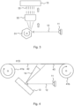
- the laser light source 11 functions as the energy source for the ablation process, laser light being applied as short pulses 12 towards the target material 13.
- the laser pulses 12 cause in the surface of the target material 13 local detachment of the material from the target as particles or other respective parts mentioned above. This way particle material flow 14 is generated, which is directed towards the material 15 to be coated.
- the correct orientation can be realised by positioning the direction of the plane of the target material surface 13 in an appropriately bevelled manner in relation to the direction of the arriving laser pulses 12 so that the direction of the motion energy releasing in the form of plasma is towards the material 15 to be coated.
- the laser source 11 can naturally be transferred in relation to the target 13, or the angle of direction of the laser beams in relation to the surface of the target 13 can be varied.
- a separate arrangement can be placed between the laser source 11 and the target 13, with which the front of laser pulses hitting the target can be made rectilinear. There is a separate Figure 4 of this arrangement.
- the plasma and particle material flow 14 in Figure 1 can be fan-shaped so that a wider area can be coated on the area of the surface 15 to be coated by using one angle of direction of the laser pulses; assuming that the material to be coated is not moved in lateral direction (seen from the Figure).
- the material to be coated can be moved, and a separate Figure 3 illustrates this embodiment.
- the detachment of the material of the target surface and the formation of particles and the transfer of material from the target to the polymer film is achieved by laser pulses applied to the target, in which the temporal duration of an individual laser pulse may be between 0.5 - 1000 ps.
- laser pulses can be produced on a repetition frequency, which is between 100 kHz - 100 MHz.
- the material for the used polymer film can be, for example, polyethylene or polypropylene.
- Thermal stress caused by the material detached by laser ablation must not cause melting or damaging of the polymer film or closing of micropores.
- Thermal stress is controlled by adjusting the ablation occurring by means of laser pulses and other detachment of material so that the thermal stress coming to the polymer film through the kinetic energy transferring from the target material and partly through thermal energy does not exceed the thermal stress of the permitted maximum temperature.
- PVD Physical Vapor Deposition
- CVD Chemical Vapor Deposition
- the film formed by the material transferring from the target material to the base material by laser ablation and as particles has to build a reliable bond with the polymer film. This can be achieved by sufficient kinetic energy of the particles, which makes possible sufficient energy to form an attachment between the inorganic coating and polymer film.
- the porosity of the forming coating has to be sufficient to make possible the diffusion of ions through the coating and film.
- FIG 2 there is shown an exemplary structural view of a separator film for lithium batteries functioning as an embodiment of the invention after it has been coated using the method of the invention.
- the separator film 22 typically used in battery applications is polymer-based and it has a microporous 23 structure, as has been stated above.
- the pores 23 of the polymer film can be of variable sizes.
- the coating 21 formed of inorganic material is of a porous structure.
- the porosity of microporous polymer films is typically between 30-50 volumetric percentages and the objective is that the porosity of the inorganic coating would be at least 30 volumetric percentages.
- the porous material is obtained by detaching material by laser ablation and by creating circumstances, in which nanoparticles typically of 10 - 100 nm or particle groups formed by these are established as detached material. As these particles and particle groups accumulate on the surface of the polymer film, they form a porous coating.
- detachment of material carried out by laser ablation occurs entirely or partly through molten particles or particles coming off from the target material, which form a coating of inorganic material on the surface of the polymer film.
- the previous mechanism produces a finer particle distribution so that also the pore distribution becomes finer.
- the coating is often generated with both mechanisms, which is additionally complemented by the plasma generated as the result of laser ablation.
- the thickness of the thin film to be produced on the surface of a polymer film is at least 50 nm. In another example the thickness of the thin film to be produced on the surface of the polymer film is at most 4000 nm.
- the inorganic material for the coating or thin film can be aluminium oxide, silicon oxide, or it consists of several different ceramic materials.
- the porosity of the polymer film can be between 20-70 volumetric percentages.
- the porosity of the inorganic coating can be between 20-70 volumetric percentages, and in a second embodiment 30-55 volumetric percentages can be selected as the parameter interval for the porosity in question.
- 30-55 volumetric percentages can be selected as the parameter interval for the porosity in question.
- the properties of the gas form one central process parameter.
- the laser ablation and the coating occur in a vacuum chamber, vacuum or background gas, to which a controlled pressure can be applied.
- a controlled pressure can be applied.
- One option is to set the pressure between 10 -8 - 1000 mbar.
- this can be carried out by disintegrating the laser pulses by rotating mirrors into a laser pulse front in the same plane.
- This arrangement is illustrated in Figure 3 .
- the laser pulses 12 of the laser source 11 are thus directed to the rotating mirrors 31.
- This type of a mirror structure can be, for example, a hexagonal and rotatable mirror surface.
- the laser pulses 12 are reflected from the rotating mirrors 31 into a fan-shaped laser pulse formation (or laser beam distribution), and the said reflected pulses are guided to a telecentric lens 32.
- the laser pulse front can be aligned essentially as a rectilinear laser pulse front 33 so that the laser pulses hit the target material 13 in the same angle. In the example of this figure the said angle is 90°.
- the separator film is well suited for coating so that material is reeled off from a roll to be coated to the desired width in the coating chamber.
- a principle figure of this application option is illustrated in Figure 4 .
- Material is targeted to the desired coating width from one or several coating sources so that material is continuously reeled off from the roll for coating, and after the material has passed the coating zone, it is reassembled to the roll.
- This method can be called a roll-to-roll principle.
- the separator film 42 to be coated is originally found around the roll 41a.
- the ablation apparatus with laser sources 11 and target material 13 is included as has been described above.
- the laser pulses 12 make the material to come off as the particle flow 14 (in other words in the form of a material flux) towards the material 42 to be coated, and as a result of adhesion the coated polymer film 43 is produced.
- the coated polymer film 43 is allowed to rotate around the second roll 41b, the direction of motion of the film being from left to right in the situation in Figure 4 .
- the roll structures 41a, 41b can be controlled by motors.
- the separator film to be coated can be the whole area of the surface or only part of the surface seen from the direction of depth in the Figure. Likewise in the direction of motion of the film a desired part (length) of the film can be selected to be coated, or alternatively, the whole roll can be processed from the beginning to the end so that the entire roll becomes coated.
- An inorganic coated material layer can thus consist of two or several material layers, which are prepared by using at least two different target materials.
- the coating can be made in at least two stages so that in the coating process a tight inorganic coating is first made on a porous polymer film so that the thickness of this coating is at most 100 nm. After this a further coating is applied either on the prepared coating or on the opposite surface of the porous polymer film so that the porosity of the further coating is bigger than 30%.
- the percentage share of the porosity of the coating layer refers to the share of empty volume (openings) from the whole volume defined by the edge surfaces of the coating.
- the porous coating can be made first and after this the said thin tight coating either on the porous coating or on the opposite side of the polymer film.
- an inorganic coating with a porosity of less than 30% is first applied on the porous polymer film so that the thickness of the coating is at most 100 nm. After this a further coating is applied either on the prepared coating or on the opposite surface of the porous polymer film so that the porosity of the further coating is bigger than 30%.
- the more porous coating can be prepared first and after this the said less porous coating can be applied on the more porous coating or on the opposite side of the polymer film.
- the porosity of the coating is chosen as 0% in the method so that the coating becomes tight, and further in the method the thickness of the coating produced is at most 100 nm.
- Porosity can thus be varied between different stages of the coating, and when needed, the porosity parameter can be selected as zero so that the layer in question is practically non-porous, i.e. a fully tight material layer.
- the inventive idea of the invention also includes the manufactured product, i.e. separator film in addition to the manufacturing method.
- the separator film comprises a porous polymer film, a porous coating of inorganic material, and in the separator film the attachment of the porous coating on the surface of the porous polymer film has been carried out by means of laser ablation.
Landscapes
- Chemical & Material Sciences (AREA)
- Chemical Kinetics & Catalysis (AREA)
- Engineering & Computer Science (AREA)
- General Chemical & Material Sciences (AREA)
- Electrochemistry (AREA)
- Metallurgy (AREA)
- Materials Engineering (AREA)
- Mechanical Engineering (AREA)
- Organic Chemistry (AREA)
- Manufacturing & Machinery (AREA)
- Inorganic Chemistry (AREA)
- Health & Medical Sciences (AREA)
- Toxicology (AREA)
- Ceramic Engineering (AREA)
- Cell Separators (AREA)
- Physical Vapour Deposition (AREA)
Claims (13)
- Verfahren zum Beschichten einer porösen Polymerfolie (15, 22, 42) zur Verwendung als Trennfolie in Li-Batterien mit einer porösen Beschichtung (21), dadurch gekennzeichnet, dass das Verfahren die folgenden Schritte umfasst:- Laserpulse (12) mit einer Dauer von 0,5 - 1000 ps werden auf ein Target (13) angewendet,- anorganisches Material (14) wird durch Laserablation vom Target (13) abgelöst,- abgelöstes anorganisches Material (14) wird auf mindestens eine Oberfläche oder einen Teil der Oberfläche (15, 22, 42) der Polymerfolie gerichtet,- eine poröse Beschichtung (21) wird auf mindestens einer Oberfläche oder einem Teil der Oberfläche (15, 22, 42) der Polymerfolie erzeugt, wobei das anorganische Material (14) an der Oberfläche der Polymerfolie haftet,- die Porosität der anorganischen Beschichtung (21) ist grundsätzlich durchgängig, was es ermöglicht, dass ein Elektrolyt die Polymerfolie (15, 22, 42) befeuchtet, und- die Porosität der anorganischen porösen Beschichtung (21) liegt zwischen 20 - 70 Volumenprozent.
- Verfahren nach Anspruch 1, dadurch gekennzeichnet, dass die auf die Oberfläche der Polymerfolie (15, 22, 42) aufzubringende poröse Beschichtung (21) eine dünne Folie ist und ihre Dicke mindestens 50 nm beträgt.
- Verfahren nach Anspruch 1, dadurch gekennzeichnet, dass das in der Beschichtung verwendete anorganische Material ein Oxid, Nitrid oder Borid ist.
- Verfahren nach irgendeinem der vorhergehenden Ansprüche 1 - 3, dadurch gekennzeichnet, dass das Material der Polymerfolie (15, 22, 42) Polyethylen oder Polypropylen ist.
- Verfahren nach irgendeinem der vorhergehenden Ansprüche 1 - 4, dadurch gekennzeichnet, dass die Porosität der Polymerfolie (15, 22, 42) zwischen 20 - 70 Volumenprozent liegt.
- Verfahren nach irgendeinem der vorhergehenden Ansprüche 1 - 5, dadurch gekennzeichnet, dass bei dem Beschichtungsverfahren sich die Polymerfolie (15, 22, 42) von einer ersten Walze (41a) zu einer zweiten Walze (41b) bewegt und der mittels Laserpulsen (12) vom Target (13) abzulösende Materialfluss (14) simultan auf mindestens eine Oberfläche oder einen Teil der Oberfläche (15, 22, 42) der Polymerfolie geführt wird, wodurch eine anorganisches Material umfassende Beschichtung gebildet wird.
- Verfahren nach irgendeinem der vorhergehenden Ansprüche 1 - 6, dadurch gekennzeichnet, dass die Laserpulse (12) auf rotierende Spiegel (31) geführt werden, in denen eine fächerförmige Laserstrahlverteilung gebildet wird, die auf eine telezentrische Linse (32) gerichtet wird, wobei die Linse verwendet wird, um eine im Wesentlichen geradlinige Front (33) von Laserpulsen zu bilden, die weiter auf das Target (13) gerichtet wird, um das Material abzulösen.
- Verfahren nach irgendeinem der vorhergehenden Ansprüche 1 - 7, dadurch gekennzeichnet, dass die Laserablation und die Beschichtung in einer Vakuumkammer, im Vakuum oder im Hintergrundgas und bei einem kontrollierten Druck von 10-8 - 1000 mbar erfolgen.
- Verfahren nach Anspruch 1, dadurch gekennzeichnet, dass das anorganische Material (14) Aluminiumoxid, Siliciumoxid ist oder es aus mehreren unterschiedlichen keramischen Materialien besteht.
- Verfahren nach irgendeinem der vorhergehenden Ansprüche 1 - 9, dadurch gekennzeichnet, dass die poröse Beschichtung (21) aus zwei oder mehreren Materialschichten besteht, die unter Verwendung von mindestens zwei unterschiedlichen Targetmaterialien (13) hergestellt werden.
- Verfahren nach irgendeinem der vorhergehenden Ansprüche 1 - 10, dadurch gekennzeichnet, dass beim Beschichtungsprozess zunächst eine dichte anorganische Beschichtung auf der porösen Polymerfolie (15, 22, 42) hergestellt wird, sodass die Dicke der dichten anorganischen Beschichtung höchstens 100 nm beträgt, woraufhin eine weitere Beschichtung entweder auf der hergestellten dichten anorganischen Beschichtung oder auf der gegenüberliegenden Seite der porösen Polymerfolie (15, 22, 42) nach dem Verfahren von Anspruch 1 vorgenommen wird, sodass die Porosität der weiteren Beschichtung größer als 30 % ist.
- Verfahren nach irgendeinem der vorhergehenden Ansprüche 1-10, dadurch gekennzeichnet, dass beim Beschichtungsprozess zunächst eine anorganische Beschichtung (21) mit einer Porosität von weniger als 30 % auf der porösen Polymerfolie (15, 22, 42) nach dem Verfahren von Anspruch 1 hergestellt wird, sodass die Dicke der anorganischen Beschichtung (21) höchstens 100 nm beträgt, woraufhin eine weitere Beschichtung entweder auf der hergestellten anorganischen Beschichtung (21) oder auf der gegenüberliegenden Seite der porösen Polymerfolie (15, 22, 42) nach dem Verfahren von Anspruch 1 vorgenommen wird, sodass die Porosität der weiteren Beschichtung größer als 30 % ist.
- Trennfolie (21, 22, 43) zur Verwendung in Li-Batterien, wobei die Trennfolie Folgendes umfasst:- eine poröse Polymerfolie (15, 22, 42),- eine poröse Beschichtung (21) aus anorganischem Material, und bei der- die Anhaftung der porösen Beschichtung (21) auf der Oberfläche der porösen Polymerfolie (15, 22, 42) mittels Laserablation durchgeführt wird, dadurch gekennzeichnet, dass die Laserablation durch Fokussieren von Laserpulsen (12) mit einer Dauer von 0,5 - 1000 ps auf ein anorganisches Material umfassendes Target (13) angeordnet wird, wodurch anorganisches Material (14) vom Target (13) abgelöst wird, durch Richten des abgelösten anorganischen Materials (14) auf mindestens eine Oberfläche oder einen Teil der Oberfläche (15, 22, 42) der Polymerfolie und durch Erzeugen einer porösen Beschichtung (21) auf mindestens einer Oberfläche oder einem Teil der Oberfläche (15, 22, 42) der Polymerfolie, wobei das anorganische Material (14) an der Oberfläche der Polymerfolie haftet, wobei- die Porosität der anorganischen Beschichtung (21) grundsätzlich durchgängig ist, was es ermöglicht, dass ein Elektrolyt die Polymerfolie (15, 22, 42) befeuchtet, und- die Porosität der anorganischen porösen Beschichtung (21) zwischen 20 - 70 Volumenprozent liegt.
Applications Claiming Priority (2)
| Application Number | Priority Date | Filing Date | Title |
|---|---|---|---|
| FI20145837A FI126659B (fi) | 2014-09-24 | 2014-09-24 | Menetelmä Li-akkujen separaattorikalvojen pinnoittamiseksi ja pinnoitettu separaattorikalvo |
| PCT/FI2015/050636 WO2016046452A1 (en) | 2014-09-24 | 2015-09-23 | Method for coating separator films of lithium batteries and a coated separator film |
Publications (3)
| Publication Number | Publication Date |
|---|---|
| EP3198668A1 EP3198668A1 (de) | 2017-08-02 |
| EP3198668A4 EP3198668A4 (de) | 2018-04-11 |
| EP3198668B1 true EP3198668B1 (de) | 2024-03-27 |
Family
ID=55580364
Family Applications (1)
| Application Number | Title | Priority Date | Filing Date |
|---|---|---|---|
| EP15845097.3A Active EP3198668B1 (de) | 2014-09-24 | 2015-09-23 | Verfahren zur beschichtung von trennfolien von lithiumbatterien und beschichtete separatorfolie |
Country Status (9)
| Country | Link |
|---|---|
| US (1) | US10573868B2 (de) |
| EP (1) | EP3198668B1 (de) |
| JP (1) | JP2017533547A (de) |
| KR (1) | KR20170056701A (de) |
| CN (1) | CN107112475A (de) |
| ES (1) | ES2981605T3 (de) |
| FI (1) | FI126659B (de) |
| HU (1) | HUE067498T2 (de) |
| WO (1) | WO2016046452A1 (de) |
Families Citing this family (7)
| Publication number | Priority date | Publication date | Assignee | Title |
|---|---|---|---|---|
| US10367181B2 (en) * | 2015-10-30 | 2019-07-30 | Panasonic Intellectual Property Management Co., Ltd. | Lithium-ion battery |
| KR20190002562A (ko) * | 2016-04-25 | 2019-01-08 | 어플라이드 머티어리얼스, 인코포레이티드 | 배터리 애플리케이션들을 위한 세퍼레이터들의 생산을 위한 방법 및 장치 |
| FI20165852A7 (fi) * | 2016-11-14 | 2018-05-15 | Picodeon Ltd Oy | MENETELMÄ Li-IONIAKKUJEN SEPARAATTORIKALVOJEN JA ELEKTRODIEN PINNOITTAMISEKSI JA PINNOITETTU SEPARAATTORI- TAI ELEKTRODIKALVO |
| US10833296B2 (en) | 2017-09-26 | 2020-11-10 | International Business Machines Corporation | Thin film solid-state microbattery packaging |
| CN112534636A (zh) | 2018-08-21 | 2021-03-19 | 应用材料公司 | 在用于电池的隔板上的超薄陶瓷涂层 |
| WO2023200194A1 (ko) * | 2022-04-15 | 2023-10-19 | 주식회사 엘지에너지솔루션 | 전지셀 추적 장치 |
| CN115275507A (zh) * | 2022-08-09 | 2022-11-01 | 南木纳米科技(北京)有限公司 | 一种干法隔膜涂布机 |
Citations (2)
| Publication number | Priority date | Publication date | Assignee | Title |
|---|---|---|---|---|
| US20120115035A1 (en) * | 2010-05-31 | 2012-05-10 | Sumitomo Electric Toyama Co., Ltd. | Three-dimensional net-like aluminum porous body, electrode using the aluminum porous body, nonaqueous electrolyte battery using the electrode, and nonaqueous electrolyte capacitor using the electrode |
| US20120154982A1 (en) * | 2010-05-31 | 2012-06-21 | Sumitomo Electric Industries, Ltd. | Capacitor, and method for producing the same |
Family Cites Families (19)
| Publication number | Priority date | Publication date | Assignee | Title |
|---|---|---|---|---|
| JP3255469B2 (ja) | 1992-11-30 | 2002-02-12 | 三菱電機株式会社 | レーザ薄膜形成装置 |
| AUPO912797A0 (en) | 1997-09-11 | 1997-10-02 | Australian National University, The | Ultrafast laser deposition method |
| JP2000307215A (ja) * | 1999-04-19 | 2000-11-02 | Nippon Steel Chem Co Ltd | 配線板の加工方法 |
| US6274207B1 (en) * | 1999-05-21 | 2001-08-14 | The Board Of Regents, The University Of Texas System | Method of coating three dimensional objects with molecular sieves |
| KR100467705B1 (ko) * | 2002-11-02 | 2005-01-24 | 삼성에스디아이 주식회사 | 무기 보호막을 갖는 세퍼레이타 및 이를 채용한 리튬 전지 |
| FI20060177A7 (fi) | 2006-02-23 | 2007-08-24 | Picodeon Ltd Oy | Menetelmä tuottaa hyvälaatuisia pintoja ja hyvälaatuisen pinnan omaava tuote |
| FI20060178A7 (fi) * | 2006-02-23 | 2007-08-24 | Picodeon Ltd Oy | Pinnoitusmenetelmä |
| CN104167464A (zh) | 2006-02-23 | 2014-11-26 | 皮克迪昂有限公司 | 太阳能电池以及用于生产太阳能电池的设备和方法 |
| JP4943242B2 (ja) * | 2007-06-20 | 2012-05-30 | ソニー株式会社 | リチウムイオン二次電池 |
| JP5467345B2 (ja) * | 2009-06-05 | 2014-04-09 | パナソニック株式会社 | ディスプレイパネルへの塗布方法およびディスプレイパネルの製造方法 |
| JP2011060668A (ja) * | 2009-09-11 | 2011-03-24 | Fujikura Ltd | レーザー蒸着法による長尺酸化物超電導導体の製造方法 |
| RU2585252C2 (ru) * | 2010-12-03 | 2016-05-27 | Инмэт Глобал, Ллк | Термостойкий слой для неводной и твердотельной батареи и способ его получения |
| US8900743B2 (en) | 2011-10-27 | 2014-12-02 | Sakti3, Inc. | Barrier for thin film lithium batteries made on flexible substrates and related methods |
| CN103137930A (zh) * | 2011-11-24 | 2013-06-05 | 比亚迪股份有限公司 | 一种锂离子电池隔膜及其制备方法、含有该隔膜的锂离子电池 |
| CN103137929A (zh) * | 2011-11-24 | 2013-06-05 | 比亚迪股份有限公司 | 一种锂离子电池隔膜及其制备方法、含有该隔膜的锂离子电池 |
| KR101955061B1 (ko) * | 2012-03-06 | 2019-03-06 | 가부시키가이샤 무라타 세이사쿠쇼 | 세퍼레이터, 전지, 전지 팩, 전자 기기, 전동 차량, 축전 장치 및 전력 시스템 |
| US9209443B2 (en) * | 2013-01-10 | 2015-12-08 | Sabic Global Technologies B.V. | Laser-perforated porous solid-state films and applications thereof |
| US10164231B2 (en) | 2013-02-05 | 2018-12-25 | Hrl Laboratories, Llc | Separators for lithium-sulfur batteries |
| US20140272595A1 (en) * | 2013-03-15 | 2014-09-18 | Basf Se | Compositions for use as protective layers and other components in electrochemical cells |
-
2014
- 2014-09-24 FI FI20145837A patent/FI126659B/fi active IP Right Grant
-
2015
- 2015-09-23 KR KR1020177010953A patent/KR20170056701A/ko not_active Ceased
- 2015-09-23 HU HUE15845097A patent/HUE067498T2/hu unknown
- 2015-09-23 JP JP2017516951A patent/JP2017533547A/ja active Pending
- 2015-09-23 ES ES15845097T patent/ES2981605T3/es active Active
- 2015-09-23 WO PCT/FI2015/050636 patent/WO2016046452A1/en not_active Ceased
- 2015-09-23 CN CN201580058156.8A patent/CN107112475A/zh active Pending
- 2015-09-23 US US15/513,801 patent/US10573868B2/en active Active
- 2015-09-23 EP EP15845097.3A patent/EP3198668B1/de active Active
Patent Citations (2)
| Publication number | Priority date | Publication date | Assignee | Title |
|---|---|---|---|---|
| US20120115035A1 (en) * | 2010-05-31 | 2012-05-10 | Sumitomo Electric Toyama Co., Ltd. | Three-dimensional net-like aluminum porous body, electrode using the aluminum porous body, nonaqueous electrolyte battery using the electrode, and nonaqueous electrolyte capacitor using the electrode |
| US20120154982A1 (en) * | 2010-05-31 | 2012-06-21 | Sumitomo Electric Industries, Ltd. | Capacitor, and method for producing the same |
Also Published As
| Publication number | Publication date |
|---|---|
| HUE067498T2 (hu) | 2024-10-28 |
| US10573868B2 (en) | 2020-02-25 |
| EP3198668A4 (de) | 2018-04-11 |
| FI126659B (fi) | 2017-03-31 |
| EP3198668A1 (de) | 2017-08-02 |
| US20180233729A1 (en) | 2018-08-16 |
| JP2017533547A (ja) | 2017-11-09 |
| KR20170056701A (ko) | 2017-05-23 |
| ES2981605T3 (es) | 2024-10-09 |
| FI20145837A7 (fi) | 2016-03-25 |
| CN107112475A (zh) | 2017-08-29 |
| WO2016046452A1 (en) | 2016-03-31 |
Similar Documents
| Publication | Publication Date | Title |
|---|---|---|
| EP3198668B1 (de) | Verfahren zur beschichtung von trennfolien von lithiumbatterien und beschichtete separatorfolie | |
| CN108140803B (zh) | 使用颗粒的基板涂覆的方法和实施该方法的装置 | |
| KR102514460B1 (ko) | 배터리 세퍼레이터들 상의 리튬 금속 코팅 | |
| KR102357946B1 (ko) | 올레핀 분리기가 없는 Li-이온 배터리 | |
| Lee et al. | Effect of Al2O3 coatings prepared by RF sputtering on polyethylene separators for high-power lithium ion batteries | |
| US9991486B2 (en) | Ion-conducting solid-state separator | |
| FI130187B (fi) | Menetelmä litiumia sisältävän materiaalikerroksen tai monikerrosrakenteen valmistamiseksi laserablaatiopinnoitusta käyttäen | |
| JP2012506130A (ja) | リチウムイオン電池 | |
| US11111576B2 (en) | Method for producing nanostructured layers | |
| WO2018087427A1 (en) | Method for coating separator films and electrodes of li ion batteries and a coated separator or electrode film | |
| WO2018134485A1 (en) | Method for the manufacture of cathode materials for nanostructured li ion batteries utilising short-term laser pulses | |
| US20240136495A1 (en) | Method for manufacturing an electrochemical component comprising a lithium metal anode and an ion-conductive inorganic material layer | |
| Lee et al. | Nano Ceramic Coating on Polypropylene Separator for Safety-Enhanced Lithium Secondary Battery | |
| Gibson et al. | Applications of Pulsed Laser Ablation in Li-Ion Battery Research | |
| JP2025532233A (ja) | 電池電極用集電体 | |
| MX2011011550A (es) | Esquema hibrido in-situ de plasma/laser. |
Legal Events
| Date | Code | Title | Description |
|---|---|---|---|
| STAA | Information on the status of an ep patent application or granted ep patent |
Free format text: STATUS: THE INTERNATIONAL PUBLICATION HAS BEEN MADE |
|
| PUAI | Public reference made under article 153(3) epc to a published international application that has entered the european phase |
Free format text: ORIGINAL CODE: 0009012 |
|
| STAA | Information on the status of an ep patent application or granted ep patent |
Free format text: STATUS: REQUEST FOR EXAMINATION WAS MADE |
|
| 17P | Request for examination filed |
Effective date: 20170406 |
|
| AK | Designated contracting states |
Kind code of ref document: A1 Designated state(s): AL AT BE BG CH CY CZ DE DK EE ES FI FR GB GR HR HU IE IS IT LI LT LU LV MC MK MT NL NO PL PT RO RS SE SI SK SM TR |
|
| AX | Request for extension of the european patent |
Extension state: BA ME |
|
| DAV | Request for validation of the european patent (deleted) | ||
| DAX | Request for extension of the european patent (deleted) | ||
| A4 | Supplementary search report drawn up and despatched |
Effective date: 20180308 |
|
| RIC1 | Information provided on ipc code assigned before grant |
Ipc: H01M 2/14 20060101AFI20180303BHEP Ipc: H01M 2/16 20060101ALI20180303BHEP Ipc: C23C 14/28 20060101ALI20180303BHEP Ipc: H01M 10/052 20100101ALI20180303BHEP |
|
| 19U | Interruption of proceedings before grant |
Effective date: 20180306 |
|
| 19W | Proceedings resumed before grant after interruption of proceedings |
Effective date: 20190502 |
|
| RAP1 | Party data changed (applicant data changed or rights of an application transferred) |
Owner name: PULSEDEON OY |
|
| STAA | Information on the status of an ep patent application or granted ep patent |
Free format text: STATUS: EXAMINATION IS IN PROGRESS |
|
| 17Q | First examination report despatched |
Effective date: 20200703 |
|
| REG | Reference to a national code |
Ref country code: DE Ref legal event code: R079 Free format text: PREVIOUS MAIN CLASS: H01M0002140000 Ipc: H01M0010052000 Ref country code: DE Ref legal event code: R079 Ref document number: 602015088097 Country of ref document: DE Free format text: PREVIOUS MAIN CLASS: H01M0002140000 Ipc: H01M0010052000 |
|
| RIC1 | Information provided on ipc code assigned before grant |
Ipc: C23C 14/08 20060101ALI20230925BHEP Ipc: C23C 14/56 20060101ALI20230925BHEP Ipc: C23C 14/10 20060101ALI20230925BHEP Ipc: H01M 50/491 20210101ALI20230925BHEP Ipc: H01M 50/403 20210101ALI20230925BHEP Ipc: H01M 50/434 20210101ALI20230925BHEP Ipc: H01M 50/451 20210101ALI20230925BHEP Ipc: H01M 50/457 20210101ALI20230925BHEP Ipc: C23C 14/28 20060101ALI20230925BHEP Ipc: H01M 10/052 20100101AFI20230925BHEP |
|
| GRAP | Despatch of communication of intention to grant a patent |
Free format text: ORIGINAL CODE: EPIDOSNIGR1 |
|
| STAA | Information on the status of an ep patent application or granted ep patent |
Free format text: STATUS: GRANT OF PATENT IS INTENDED |
|
| INTG | Intention to grant announced |
Effective date: 20231103 |
|
| RIN1 | Information on inventor provided before grant (corrected) |
Inventor name: ZOLOTUKHIN, ALEKSEY Inventor name: KEKKONEN, VILLE Inventor name: LIIMATAINEN, JARI |
|
| GRAS | Grant fee paid |
Free format text: ORIGINAL CODE: EPIDOSNIGR3 |
|
| GRAA | (expected) grant |
Free format text: ORIGINAL CODE: 0009210 |
|
| STAA | Information on the status of an ep patent application or granted ep patent |
Free format text: STATUS: THE PATENT HAS BEEN GRANTED |
|
| AK | Designated contracting states |
Kind code of ref document: B1 Designated state(s): AL AT BE BG CH CY CZ DE DK EE ES FI FR GB GR HR HU IE IS IT LI LT LU LV MC MK MT NL NO PL PT RO RS SE SI SK SM TR |
|
| REG | Reference to a national code |
Ref country code: GB Ref legal event code: FG4D |
|
| RIN1 | Information on inventor provided before grant (corrected) |
Inventor name: ZOLOTUKHIN, ALEKSEY Inventor name: KEKKONEN, VILLE Inventor name: LIIMATAINEN, JARI |
|
| REG | Reference to a national code |
Ref country code: CH Ref legal event code: EP |
|
| REG | Reference to a national code |
Ref country code: DE Ref legal event code: R096 Ref document number: 602015088097 Country of ref document: DE |
|
| REG | Reference to a national code |
Ref country code: IE Ref legal event code: FG4D |
|
| P01 | Opt-out of the competence of the unified patent court (upc) registered |
Effective date: 20240405 |
|
| PG25 | Lapsed in a contracting state [announced via postgrant information from national office to epo] |
Ref country code: LT Free format text: LAPSE BECAUSE OF FAILURE TO SUBMIT A TRANSLATION OF THE DESCRIPTION OR TO PAY THE FEE WITHIN THE PRESCRIBED TIME-LIMIT Effective date: 20240327 |
|
| REG | Reference to a national code |
Ref country code: LT Ref legal event code: MG9D |
|
| PG25 | Lapsed in a contracting state [announced via postgrant information from national office to epo] |
Ref country code: GR Free format text: LAPSE BECAUSE OF FAILURE TO SUBMIT A TRANSLATION OF THE DESCRIPTION OR TO PAY THE FEE WITHIN THE PRESCRIBED TIME-LIMIT Effective date: 20240628 |
|
| REG | Reference to a national code |
Ref country code: SE Ref legal event code: TRGR |
|
| PG25 | Lapsed in a contracting state [announced via postgrant information from national office to epo] |
Ref country code: RS Free format text: LAPSE BECAUSE OF FAILURE TO SUBMIT A TRANSLATION OF THE DESCRIPTION OR TO PAY THE FEE WITHIN THE PRESCRIBED TIME-LIMIT Effective date: 20240627 Ref country code: HR Free format text: LAPSE BECAUSE OF FAILURE TO SUBMIT A TRANSLATION OF THE DESCRIPTION OR TO PAY THE FEE WITHIN THE PRESCRIBED TIME-LIMIT Effective date: 20240327 |
|
| PG25 | Lapsed in a contracting state [announced via postgrant information from national office to epo] |
Ref country code: RS Free format text: LAPSE BECAUSE OF FAILURE TO SUBMIT A TRANSLATION OF THE DESCRIPTION OR TO PAY THE FEE WITHIN THE PRESCRIBED TIME-LIMIT Effective date: 20240627 Ref country code: NO Free format text: LAPSE BECAUSE OF FAILURE TO SUBMIT A TRANSLATION OF THE DESCRIPTION OR TO PAY THE FEE WITHIN THE PRESCRIBED TIME-LIMIT Effective date: 20240627 Ref country code: LT Free format text: LAPSE BECAUSE OF FAILURE TO SUBMIT A TRANSLATION OF THE DESCRIPTION OR TO PAY THE FEE WITHIN THE PRESCRIBED TIME-LIMIT Effective date: 20240327 Ref country code: HR Free format text: LAPSE BECAUSE OF FAILURE TO SUBMIT A TRANSLATION OF THE DESCRIPTION OR TO PAY THE FEE WITHIN THE PRESCRIBED TIME-LIMIT Effective date: 20240327 Ref country code: GR Free format text: LAPSE BECAUSE OF FAILURE TO SUBMIT A TRANSLATION OF THE DESCRIPTION OR TO PAY THE FEE WITHIN THE PRESCRIBED TIME-LIMIT Effective date: 20240628 Ref country code: FI Free format text: LAPSE BECAUSE OF FAILURE TO SUBMIT A TRANSLATION OF THE DESCRIPTION OR TO PAY THE FEE WITHIN THE PRESCRIBED TIME-LIMIT Effective date: 20240327 Ref country code: BG Free format text: LAPSE BECAUSE OF FAILURE TO SUBMIT A TRANSLATION OF THE DESCRIPTION OR TO PAY THE FEE WITHIN THE PRESCRIBED TIME-LIMIT Effective date: 20240327 |
|
| REG | Reference to a national code |
Ref country code: NL Ref legal event code: MP Effective date: 20240327 |
|
| PG25 | Lapsed in a contracting state [announced via postgrant information from national office to epo] |
Ref country code: LV Free format text: LAPSE BECAUSE OF FAILURE TO SUBMIT A TRANSLATION OF THE DESCRIPTION OR TO PAY THE FEE WITHIN THE PRESCRIBED TIME-LIMIT Effective date: 20240327 |
|
| PG25 | Lapsed in a contracting state [announced via postgrant information from national office to epo] |
Ref country code: NL Free format text: LAPSE BECAUSE OF FAILURE TO SUBMIT A TRANSLATION OF THE DESCRIPTION OR TO PAY THE FEE WITHIN THE PRESCRIBED TIME-LIMIT Effective date: 20240327 |
|
| REG | Reference to a national code |
Ref country code: AT Ref legal event code: MK05 Ref document number: 1670792 Country of ref document: AT Kind code of ref document: T Effective date: 20240327 |
|
| PG25 | Lapsed in a contracting state [announced via postgrant information from national office to epo] |
Ref country code: NL Free format text: LAPSE BECAUSE OF FAILURE TO SUBMIT A TRANSLATION OF THE DESCRIPTION OR TO PAY THE FEE WITHIN THE PRESCRIBED TIME-LIMIT Effective date: 20240327 |
|
| PG25 | Lapsed in a contracting state [announced via postgrant information from national office to epo] |
Ref country code: IS Free format text: LAPSE BECAUSE OF FAILURE TO SUBMIT A TRANSLATION OF THE DESCRIPTION OR TO PAY THE FEE WITHIN THE PRESCRIBED TIME-LIMIT Effective date: 20240727 |
|
| REG | Reference to a national code |
Ref country code: ES Ref legal event code: FG2A Ref document number: 2981605 Country of ref document: ES Kind code of ref document: T3 Effective date: 20241009 |
|
| PG25 | Lapsed in a contracting state [announced via postgrant information from national office to epo] |
Ref country code: SM Free format text: LAPSE BECAUSE OF FAILURE TO SUBMIT A TRANSLATION OF THE DESCRIPTION OR TO PAY THE FEE WITHIN THE PRESCRIBED TIME-LIMIT Effective date: 20240327 Ref country code: PT Free format text: LAPSE BECAUSE OF FAILURE TO SUBMIT A TRANSLATION OF THE DESCRIPTION OR TO PAY THE FEE WITHIN THE PRESCRIBED TIME-LIMIT Effective date: 20240729 |
|
| PG25 | Lapsed in a contracting state [announced via postgrant information from national office to epo] |
Ref country code: CZ Free format text: LAPSE BECAUSE OF FAILURE TO SUBMIT A TRANSLATION OF THE DESCRIPTION OR TO PAY THE FEE WITHIN THE PRESCRIBED TIME-LIMIT Effective date: 20240327 Ref country code: EE Free format text: LAPSE BECAUSE OF FAILURE TO SUBMIT A TRANSLATION OF THE DESCRIPTION OR TO PAY THE FEE WITHIN THE PRESCRIBED TIME-LIMIT Effective date: 20240327 |
|
| PG25 | Lapsed in a contracting state [announced via postgrant information from national office to epo] |
Ref country code: AT Free format text: LAPSE BECAUSE OF FAILURE TO SUBMIT A TRANSLATION OF THE DESCRIPTION OR TO PAY THE FEE WITHIN THE PRESCRIBED TIME-LIMIT Effective date: 20240327 |
|
| PG25 | Lapsed in a contracting state [announced via postgrant information from national office to epo] |
Ref country code: PL Free format text: LAPSE BECAUSE OF FAILURE TO SUBMIT A TRANSLATION OF THE DESCRIPTION OR TO PAY THE FEE WITHIN THE PRESCRIBED TIME-LIMIT Effective date: 20240327 |
|
| REG | Reference to a national code |
Ref country code: HU Ref legal event code: AG4A Ref document number: E067498 Country of ref document: HU |
|
| PG25 | Lapsed in a contracting state [announced via postgrant information from national office to epo] |
Ref country code: SK Free format text: LAPSE BECAUSE OF FAILURE TO SUBMIT A TRANSLATION OF THE DESCRIPTION OR TO PAY THE FEE WITHIN THE PRESCRIBED TIME-LIMIT Effective date: 20240327 |
|
| PG25 | Lapsed in a contracting state [announced via postgrant information from national office to epo] |
Ref country code: SM Free format text: LAPSE BECAUSE OF FAILURE TO SUBMIT A TRANSLATION OF THE DESCRIPTION OR TO PAY THE FEE WITHIN THE PRESCRIBED TIME-LIMIT Effective date: 20240327 Ref country code: SK Free format text: LAPSE BECAUSE OF FAILURE TO SUBMIT A TRANSLATION OF THE DESCRIPTION OR TO PAY THE FEE WITHIN THE PRESCRIBED TIME-LIMIT Effective date: 20240327 Ref country code: RO Free format text: LAPSE BECAUSE OF FAILURE TO SUBMIT A TRANSLATION OF THE DESCRIPTION OR TO PAY THE FEE WITHIN THE PRESCRIBED TIME-LIMIT Effective date: 20240327 Ref country code: PT Free format text: LAPSE BECAUSE OF FAILURE TO SUBMIT A TRANSLATION OF THE DESCRIPTION OR TO PAY THE FEE WITHIN THE PRESCRIBED TIME-LIMIT Effective date: 20240729 Ref country code: PL Free format text: LAPSE BECAUSE OF FAILURE TO SUBMIT A TRANSLATION OF THE DESCRIPTION OR TO PAY THE FEE WITHIN THE PRESCRIBED TIME-LIMIT Effective date: 20240327 Ref country code: IS Free format text: LAPSE BECAUSE OF FAILURE TO SUBMIT A TRANSLATION OF THE DESCRIPTION OR TO PAY THE FEE WITHIN THE PRESCRIBED TIME-LIMIT Effective date: 20240727 Ref country code: EE Free format text: LAPSE BECAUSE OF FAILURE TO SUBMIT A TRANSLATION OF THE DESCRIPTION OR TO PAY THE FEE WITHIN THE PRESCRIBED TIME-LIMIT Effective date: 20240327 Ref country code: CZ Free format text: LAPSE BECAUSE OF FAILURE TO SUBMIT A TRANSLATION OF THE DESCRIPTION OR TO PAY THE FEE WITHIN THE PRESCRIBED TIME-LIMIT Effective date: 20240327 Ref country code: AT Free format text: LAPSE BECAUSE OF FAILURE TO SUBMIT A TRANSLATION OF THE DESCRIPTION OR TO PAY THE FEE WITHIN THE PRESCRIBED TIME-LIMIT Effective date: 20240327 |
|
| REG | Reference to a national code |
Ref country code: DE Ref legal event code: R097 Ref document number: 602015088097 Country of ref document: DE |
|
| PG25 | Lapsed in a contracting state [announced via postgrant information from national office to epo] |
Ref country code: DK Free format text: LAPSE BECAUSE OF FAILURE TO SUBMIT A TRANSLATION OF THE DESCRIPTION OR TO PAY THE FEE WITHIN THE PRESCRIBED TIME-LIMIT Effective date: 20240327 |
|
| PG25 | Lapsed in a contracting state [announced via postgrant information from national office to epo] |
Ref country code: DK Free format text: LAPSE BECAUSE OF FAILURE TO SUBMIT A TRANSLATION OF THE DESCRIPTION OR TO PAY THE FEE WITHIN THE PRESCRIBED TIME-LIMIT Effective date: 20240327 |
|
| PLBE | No opposition filed within time limit |
Free format text: ORIGINAL CODE: 0009261 |
|
| STAA | Information on the status of an ep patent application or granted ep patent |
Free format text: STATUS: NO OPPOSITION FILED WITHIN TIME LIMIT |
|
| 26N | No opposition filed |
Effective date: 20250103 |
|
| PG25 | Lapsed in a contracting state [announced via postgrant information from national office to epo] |
Ref country code: SI Free format text: LAPSE BECAUSE OF FAILURE TO SUBMIT A TRANSLATION OF THE DESCRIPTION OR TO PAY THE FEE WITHIN THE PRESCRIBED TIME-LIMIT Effective date: 20240327 Ref country code: MC Free format text: LAPSE BECAUSE OF FAILURE TO SUBMIT A TRANSLATION OF THE DESCRIPTION OR TO PAY THE FEE WITHIN THE PRESCRIBED TIME-LIMIT Effective date: 20240327 |
|
| PG25 | Lapsed in a contracting state [announced via postgrant information from national office to epo] |
Ref country code: LU Free format text: LAPSE BECAUSE OF NON-PAYMENT OF DUE FEES Effective date: 20240923 |
|
| REG | Reference to a national code |
Ref country code: BE Ref legal event code: MM Effective date: 20240930 |
|
| PG25 | Lapsed in a contracting state [announced via postgrant information from national office to epo] |
Ref country code: BE Free format text: LAPSE BECAUSE OF NON-PAYMENT OF DUE FEES Effective date: 20240930 |
|
| PG25 | Lapsed in a contracting state [announced via postgrant information from national office to epo] |
Ref country code: IE Free format text: LAPSE BECAUSE OF NON-PAYMENT OF DUE FEES Effective date: 20240923 |
|
| REG | Reference to a national code |
Ref country code: CH Ref legal event code: U11 Free format text: ST27 STATUS EVENT CODE: U-0-0-U10-U11 (AS PROVIDED BY THE NATIONAL OFFICE) Effective date: 20251001 |
|
| PGFP | Annual fee paid to national office [announced via postgrant information from national office to epo] |
Ref country code: DE Payment date: 20250901 Year of fee payment: 11 |
|
| PGFP | Annual fee paid to national office [announced via postgrant information from national office to epo] |
Ref country code: HU Payment date: 20250827 Year of fee payment: 11 Ref country code: GB Payment date: 20250905 Year of fee payment: 11 |
|
| PGFP | Annual fee paid to national office [announced via postgrant information from national office to epo] |
Ref country code: FR Payment date: 20250909 Year of fee payment: 11 |
|
| PGFP | Annual fee paid to national office [announced via postgrant information from national office to epo] |
Ref country code: SE Payment date: 20250904 Year of fee payment: 11 |
|
| PGFP | Annual fee paid to national office [announced via postgrant information from national office to epo] |
Ref country code: IT Payment date: 20250901 Year of fee payment: 11 |
|
| PGFP | Annual fee paid to national office [announced via postgrant information from national office to epo] |
Ref country code: CH Payment date: 20251001 Year of fee payment: 11 |
|
| PG25 | Lapsed in a contracting state [announced via postgrant information from national office to epo] |
Ref country code: CY Free format text: LAPSE BECAUSE OF FAILURE TO SUBMIT A TRANSLATION OF THE DESCRIPTION OR TO PAY THE FEE WITHIN THE PRESCRIBED TIME-LIMIT; INVALID AB INITIO Effective date: 20150923 |
|
| PGFP | Annual fee paid to national office [announced via postgrant information from national office to epo] |
Ref country code: ES Payment date: 20251205 Year of fee payment: 11 |