EP3198577B1 - Système de gestion de services - Google Patents
Système de gestion de services Download PDFInfo
- Publication number
- EP3198577B1 EP3198577B1 EP15775824.4A EP15775824A EP3198577B1 EP 3198577 B1 EP3198577 B1 EP 3198577B1 EP 15775824 A EP15775824 A EP 15775824A EP 3198577 B1 EP3198577 B1 EP 3198577B1
- Authority
- EP
- European Patent Office
- Prior art keywords
- user
- gateway
- pressure
- information
- tactile
- Prior art date
- Legal status (The legal status is an assumption and is not a legal conclusion. Google has not performed a legal analysis and makes no representation as to the accuracy of the status listed.)
- Not-in-force
Links
Images


Classifications
-
- G—PHYSICS
- G08—SIGNALLING
- G08C—TRANSMISSION SYSTEMS FOR MEASURED VALUES, CONTROL OR SIMILAR SIGNALS
- G08C17/00—Arrangements for transmitting signals characterised by the use of a wireless electrical link
-
- H—ELECTRICITY
- H04—ELECTRIC COMMUNICATION TECHNIQUE
- H04L—TRANSMISSION OF DIGITAL INFORMATION, e.g. TELEGRAPHIC COMMUNICATION
- H04L12/00—Data switching networks
- H04L12/28—Data switching networks characterised by path configuration, e.g. LAN [Local Area Networks] or WAN [Wide Area Networks]
- H04L12/2803—Home automation networks
- H04L12/2823—Reporting information sensed by appliance or service execution status of appliance services in a home automation network
- H04L12/2827—Reporting to a device within the home network; wherein the reception of the information reported automatically triggers the execution of a home appliance functionality
- H04L12/2829—Reporting to a device within the home network; wherein the reception of the information reported automatically triggers the execution of a home appliance functionality involving user profiles according to which the execution of a home appliance functionality is automatically triggered
-
- H—ELECTRICITY
- H04—ELECTRIC COMMUNICATION TECHNIQUE
- H04L—TRANSMISSION OF DIGITAL INFORMATION, e.g. TELEGRAPHIC COMMUNICATION
- H04L12/00—Data switching networks
- H04L12/28—Data switching networks characterised by path configuration, e.g. LAN [Local Area Networks] or WAN [Wide Area Networks]
- H04L12/2803—Home automation networks
- H04L12/2816—Controlling appliance services of a home automation network by calling their functionalities
- H04L12/282—Controlling appliance services of a home automation network by calling their functionalities based on user interaction within the home
-
- G—PHYSICS
- G08—SIGNALLING
- G08C—TRANSMISSION SYSTEMS FOR MEASURED VALUES, CONTROL OR SIMILAR SIGNALS
- G08C2201/00—Transmission systems of control signals via wireless link
- G08C2201/40—Remote control systems using repeaters, converters, gateways
- G08C2201/41—Remote control of gateways
Definitions
- the instant application relates to the field of management systems and more particularly to managing provided services based on sensor inputs.
- Occupancy or motion sensors have long been used as a lighting control mechanism in office buildings and public areas to save energy.
- a smart home setting turning on/off or just dimming up/down light is not attractive enough for the Internet generation.
- a smarter lighting system that knows habitant's context such as indoor location, identity, activity and even healthiness will be more attractive to the Internet generation.
- Wi-Fi or sound source based localization techniques are known to localize family members in the home.
- the main disadvantages are inaccuracy and the requirements that a user has to carry certain kinds of signal emitters, such as a smart phone.
- Camera or RFID-based approaches are also found in the literature for resident activity recognition. But these solutions are too intrusive to be practical.
- a pressure sensor is a transducer that turns pressure, such as contact force, air or liquid pressure, into electrical signals.
- US patent US 2010/0257938A1 titled "Flat planner pressure transducer” describes a flat planar pressure transducer that comprises a planar insulative substrate of a rectangular configuration. The structure forms a very flat, compact pressure transducer that can be utilized with a very small footprint. Their technology is ideal for the current invention to build the pressure sensor unit.
- US patent US2008/0266112A1 titled "Valentine pillow” discloses a communication device which can receive tactile input including a word, a symbol or a pattern. Such inputs can be used to control light emitting diodes (LEDs) co-located with the pillow.
- LEDs light emitting diodes
- the Valentine pillow requires an explicit user input.
- a system for providing home care based on lighting and pressure/tactile sensors embedded in home comfort objects such as seat cushion, arm supports, shoe pads, mouse pads and neck rests is disclosed.
- Tactile sensors are manufactured to be flexible, thin and stretchable so that they are invisible and intangible to the user.
- Spatially continuous or discrete pressure distribution patterns are used to infer the location, the identity, the posture and the healthiness information regarding at least one resident or user.
- the inferred information is used to produce a light condition in favor of the resident.
- the invention can be used to create lighting condition for individual family members, for children's eye care, and generate alarm messages if a resident stays up too late at night.
- a system for managing home services comprising tactile sensor units that measure a measureable event, such as pressure, heat, blood pressure, etc., distributed about one or more home care objects.
- Information associated with the measured event(s) is provided to a processor, which forms distribution patterns associated with the measured event(s).
- An action is then determined based on the determined distribution pattern wherein conditions surrounding the home care objects (and the user(s)) are altered.
- a system for managing home services may be associated with health care, wherein information associated with tactile sensors that measure blood pressure, for example, may be collected and analyzed. The identity of the user may be determined from the collected data and appropriate actions, e.g., contact doctors, may be taken when the collected information satisfies one or more rules regarding taking the corresponding action.
- a system of managing home services may be associated with office operations, wherein information associated with tactile sensors that measure a pressure of a person working at a desk may be collected and analyzed. The identity of the user may be determined from the collected and analyzed. Appropriate actions, e.g., allow access to computer data, turn on or off lighting, etc., may be taken when the collected information satisfies one or more rules regarding collected information.
- a health status of a user may be determined and monitored.
- Health related information associated with a user may collected from one set of sensors.
- a different set of sensors may be used to determine that the user is positioned correctly and that the health related information is collected from when the user is positioned correctly. Correct positioning (or consistent position) provides consistence among health related information taken at different time.
- a social interaction status of one or more users may be determined based on information received from sensors of different types.
- sensors of a first type may be used to determine a position, location and/or identity of one or more users.
- a proximity graph may be formulated form the locations of the one or more users.
- Sensors of a second type may be used to determine a health condition associated with each of the one or more users wherein the health status is considered in view of the proximity graph.
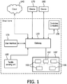
- FIG. 1 illustrates a block diagram of an exemplary system 10 in accordance with the principles of the invention.
- a tactile sensing unit 100 provides information regarding contact information that a user may apply at one or more contact points.
- the contact information may be provided continuously or periodically.
- the tactile sensing unit 100 may provide pressure information when a pressure on the tactile sensing unit 100 is detected.
- a pressure sufficient to active the tactile sensing unit 100 for providing the detected pressure information may be one that exceeds a threshold pressure value or a pressure level that is below the threshold pressure value but is present for a predetermined time.
- a pressure sufficient to exceed a threshold pressure may be one when a full size person is in contact with the tactile sensor unit.
- the pressure may be obtained from a child, having a contact pressure insufficient to exceed the threshold pressure but is in contact with the tactile sensor unit for an extended time (persistence).
- the detected pressure information may then be provided to a gateway unit 110.
- the gateway unit 110 may represent a computer or server that is in direct communication with each of the tactile sensing units.
- the communication may be one or a wired communication or a wireless communication (i.e., BLUETOOTH, WIFI, etc.).
- tactile sensing units 100 may be in communication with the gateway 110 over a large scale network, e.g., Internet, or over a local network (e.g., LAN).
- the networks may be public or private.
- one or more tactile sensing units 100 that may be grouped together or may be distributed about an area 100'.
- the area 100' containing the one or more tactile sensing units 100 may be distributed such that only selected ones of the one or more tactile sensing units 100 may be contacted by a user.
- the selected ones of the one or more tactile sensing units 100 may be in communication with a centralized controller 107 that provides collects, collates and processes the information from the selected ones of the one or more tactile sensing units 100.
- the pressure information detected by each of the one or more tactile sensing units 100 (or a collected value provide by controller 107) may then be provided to gateway 110.
- the information from selected ones of the tactile sensing units may be independently provided to the gateway 110.
- tactile sensing units 100 are described with regard to pressure, it would be appreciated that tactile sensing units 100 may be selected to measure or detect other parameters or characteristics.
- the sensing units 100 may be associated with characteristics, such as heat, temperature, and movement.
- the tactile sensing unit 100 may measure a change in heat from an ambient condition.
- Gateway 110 represents a centralized controller that receives inputs from the tactile sensing units 100 (and/or collector 107) and determines a pattern associated with the received inputs. Gateway 110 may then provide instruction to devices, e.g., controlled luminaires 130, to alter the operating state of the controlled devices (e.g., luminaires, window blinds, etc.) surrounding the user.
- devices e.g., controlled luminaires 130, to alter the operating state of the controlled devices (e.g., luminaires, window blinds, etc.) surrounding the user.
- Gateway 110 may further be in communication with a user interface device 120.
- User interface device 120 allows a user to input information to or receive information from gateway 110.
- user interface device 120 may include a display and a keyboard.
- Gateway 110 may further be in communication with a larger network 140, wherein information from the network 140 may be provided to gateway 110 or information from gateway 110 may be provided to additional devices (not shown) through network 140.
- the sofa seat cushions may include tactile sensing units 100 that detect pressure on the cushions.
- the pressure information may be provided to the gateway 110.
- the gateway 110 may further receive information regarding the status of a television and a time.
- the gateway 110 may then determine at least one characteristic of the user seating on the sofa.
- the characteristic may be one of a height, weight, a fingerprint, an identity, etc.
- the gateway 110 may then access a rules database and determine, based on the received input information, an action to be taken. For example, if the determined characteristic(s) indicates that the information from the tactile sensing unit 100 (or array 100') in the sofa cushions is associated with an adult, then no action may be invoked.
- a command may be sent from the gateway 110 to luminaries within the room associated with the sofa to gently reduce the light level. Additional, commands may be sent to the TV (another controlled device) to turn the TV off, if the TV is determined to be on. In addition, a phone call or a text message may be sent to the parents' cell phone via network 140.
- Figure 1 further illustrates devices 170, 180, which may represent controllable devices that provide inputs to, or receive inputs from, gateway 110.
- Devices 170, 180 may represent overhead lighting, for example, which may be controlled to alter the operating conditions of devices 170, 180 based on the characteristic and the associated rule.
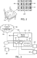
- Figure 2 illustrates an example of a cushion 201 that may include one or more tactile sensor units 100 incorporated into a seat cushion 201.
- tactile sensor units 100 are arranged as an array of sensor units 100 positioned substantially in the center of cushion 210.
- each of the tactile sensor units 100 may be identified by a unique identification.
- the unique identification may be used to determine a position of a tactile sensor unit 100.
- the position may be absolute or relative (i.e., with regard to adjacent tactile sensor units 100).
- the array 100' of tactile sensor units 100 may be identified uniquely identified and a position of an individual tactile sensor unit 100 may be determined based on the position of the array 100'.
- tactile sensor unit 100 may include a GPS (Global Positioning Satellite) system that may be used to determine an absolute location or position of the tactile sensor unit. While other sensor units 100 may have a position relative to one or more sensing units 100 having an absolute location.
- GPS Global Positioning Satellite
- the sensor units 100 may be positioned in an arbitrary manner without altering the scope of the invention.
- the array 100' shown herein is one of being a matrix format (i.e., sensing units 100 in rows and columns), it would be recognized that the term "array” as used herein may refer to a group of sensing units that are in a same local area, regardless of the relationship of one of the sensing units 100 with respect to adjacent sensing units 100.
- the tactile sensing unit 100 In order to make the tactile sensing unit 100 sensitive to contact force while being invisible and non-tangible to the user, the tactile sensing unit 100 has to be manufactured to be flexible, thin, and stretchable and fabricated underneath the surface of cushion or home comfort object (HCO).
- HCO home comfort object
- State-of-art pressure sensing technology proves the feasibility.
- US 2010/0257938A1 discloses a thin flexible pressure sensor, the contents of which are incorporated by reference herein.
- a power source for example, a button battery, may be incorporated into each sensing unit 100.
- the power source provides power to the sensing unit 100 as well as a communication module.
- energy efficient communication protocol may be chosen.
- the communication module may not be powered up until a threshold pressure is detected, for example.
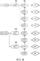
- FIG. 3 illustrates a block diagram of gateway 110 in accordance with the principles of the invention.
- gateway 110 comprises a processor (e.g., a computer or processor) 310 that is in communication with one or more of the tactile sensors 100 and/or an external network 140, as shown in Figure 1 , through a communication module 320.
- communication module 320 is a logical representation of one or more different physical communication devices that operate with one or more suitable protocols.
- communication module 320 may represent BLUETOOTH or WIFI protocols suitable for communication with tactile sensing units 100.
- Communication module 320 may also present a TCP/IP protocol suitable for internet access.
- communication module 320 may represent either wireless or wired devices that operate using the appropriate protocol.
- Processor 310 is further in communication with data base 330.
- Data base 330 includes one or more rules or expressions that determine actions based on an analysis of information received from the one or more tactile sensor units 100. Although data base 330 is shown as being contained within gateway 110, it would be recognized that data base 330 may be external to, and remotely located from, gateway 110. Processor 310 may access data contained in data base 330 through communication module 320 and network 140 without altering the scope and principles of the invention.
- Processor 310 may further be in communication with a second processor 340.
- Second processor 340 may be remotely located from processor 310 (as shown). Or the second processor 340 may be co-located with processor 310.
- Second processor 340 may include a learning module 350, which receives inputs from processors 310, 340 and determines patterns for different users based on characteristics developed from information provided by the tactile sensing units 100.
- the data base 330 may be composed of a plurality of rules that invoke actions in response to the determination of a pattern of characteristics detected or measured by corresponding tactile sensing units 100.
- each rule in the rule database 330 may be described in a "if condition then action " format.
- the rules stored in data base 330 may be stored in order forms (e.g., tables) or in other programming languages. (e.g., SQL, Java, etc.).
- three conditions are specified in the if clause (if either the son or the daughter is on sofa past 10pm) and two actions are defined in the then clause (i.e., flash the living room light and text a message (e.g., SMS, email, etc.) to the specified cell number).
- the above illustrated rules may be formulated such that if at least one child (and not necessarily either a son or daughter) is detected on the sofa, then the appropriate action may be a taken.
- a determination of the person (or persons) located on the sofa (or the HCOs) may be determined based on distribution patterns measured from sensing units 100 positioned within the sofa (or other HCOs).
- the specification of the rules may be manually provided by the user, via the user interface 120 ( FIG. 1 ).
- the user interface 120 may include a display (not shown) that provides a graphic user interface that the user may employ to specify the conditions and the actions to be taken for each determined situation. GUIs are well known in the art and a detailed discussion of the operation of GUIs is not needed.
- commonly-used rules can be defined and published online so that the user may adapt the commonly-used rules for their own settings.
- user interface 120 may be implemented as a mobile application installed on the user's smart phone.
- the graphic user interface may present an interface to the user to calibrate the identity and locate the sensor units 100, to create, update, share and remove rules.
- FIG. 4 illustrates an exemplary system configuration 400 in accordance with the principles of the invention.
- sensing units 100 are incorporated into a plurality of locations in a chair 420 and a desk 430.
- sensor units 100 may be incorporated into the seat 401 of chair 420, as shown in Figure 3 .
- Sensor units 100 may further be incorporated into the back 402 and the arms 403 of chair 420.
- Sensor units 100 incorporated into the seat 401, back 402 and arms 403 may provide information to gateway 110.
- Gateway 110 may then correlate the provided information to determine a profile of a user sitting in chair 420. For example, a pressure on selected ones of the tactile sensing units in seat 401 may distinguish between an adult and a child. Similarly, a pressure on selected ones of the tactile sensing units in back 402 may determine a height of a person sitting in chair 420.
- sensor units 100 incorporated into desk 430.
- Sensor units 100 may be incorporated directly into a top of desk 430 or may be incorporated on a place mat 404, which is positioned on the top of desk 430.
- Sensing units 100 on the top of desk 430 may determine whether the hand or arm location of a user sitting in chair 420. For example, if the user is typing on a keyboard of a laptop computer 440, as illustrated, gateway 110 may determine the position of the hands of a user by a difference in pressure exerted on the sensing units 100 between the laptop computer with hands on the keyboard and without hands on the keyboard.
- gateway 110 receiving inputs from sensing units 100 located in different positions of chair 420 and desk 430 and may determine the position of a person sitting in the chair and adjust the lighting of lamp 450 such that the lighting provided by lamp 450 is suitable for the task being performed.
- lamp 450 is shown as being a desk lamp, it would be appreciated that the lighting control may extend to overhead light (not shown) or control of window coverings (i.e., window blinds) to provide appropriate lighting for the task being perform.
- gateway 110 after determining a task being performed, based on the analyzed sensing unit 100 inputs, may adjust a combination of overhead lighting, local task lighting and window covering positions, such that adequate lighting may be projected onto the working surface (e.g., top of desk 430) while achieving a best energy efficiency.
- Figure 5 illustrates a further exemplary embodiment in accordance with the principles of the invention, wherein a placement (not shown) including sensing units 100 (not shown) may be placed such that a user applies a pressure by the positioning of their feet.
- a placement including sensing units 100 (not shown) may be placed such that a user applies a pressure by the positioning of their feet.
- greater levels of pressure, applied by a foot 500 may result in different distribution patterns (e.g., of pressures).
- Figure 5 illustrates that greater pressure may be measured in areas 520, 530 (shown with a denser degree of hashing) that in areas 540, 550 and 560 for example (shown with less degree of hashing, wherein the density of the hashing indicates a level of pressure).
- a person's identity can be recognized by the pressure the person exerts on a home care object (HCO, e.g., a seat cushion, a blanket, a footpad, etc.).
- HCO home care object
- a pressure distribution pattern e.g., 520, 530
- the pressure distribution pattern may be collected over a period of time, and thus may be used to distinguish one person over another.
- a pressure distribution pattern is the spatial distribution of pressure over multiple contact points or HCOs.
- An example pressure distribution pattern of a foot is shown in Figure 5 , wherein the greater density of hasher (or darker shading) represents greater degree of pressure.
- Figure 5 illustrates five (5) different pressure distribution patterns. However, if would be appreciated that any number of pressure distribution patterns may be formulated.
- a pressure distribution pattern may be formulated by including those points within a known distance from a point (or area) having a maximum pressure.
- a pressure distribution pattern may be formulated to include those points having a pressure greater than a threshold value, wherein the threshold value is measured with respect to the point or area having a maximum pressure (i.e., pressures greater than 75 percent of maximum pressure included in the pressure distribution pattern).
- pressure values within an overlap area of two distribution patterns may be assigned to one or both of the pressure distribution patterns.
- those points within two patterns may be assigned to that distribution pattern to which those points are closer to a maximum pressure of the two patterns.
- the number of distribution patterns may be culled, such that only those patterns satisfying a known criterion may be further processed. For example, if a maximum pressure within a distribution pattern is below a threshold value of a maximum pressure of all the distributions, (e.g., maximum pressure in a distribution pattern is less than 30 per cent of the maximum pressure of all distribution patterns) then the distribution pattern may be discarded.
- a threshold value of a maximum pressure of all the distributions e.g., maximum pressure in a distribution pattern is less than 30 per cent of the maximum pressure of all distribution patterns
- Figure 5 has been described with regard to a pressure and a pressure distribution pattern, it would be recognized that the sensing unit(s) 100 may be associated with other information and, thus, the distributions patterns may be associated with measurable events such as heat, blood pressure, heart rate, galvanic response, etc.).
- Figure 6 illustrates a block diagram of exemplary configuration of a system in accordance with the principles of the invention.
- sensing units 100 may be positioned in a seat 401, a back 402, and an arm 403 in a chair 420 in a study room.
- chairs 620, 620' in a living room may further incorporate arrays 100' in a seat 601 and/or back 602.
- Gateway 110 (not shown) may receive inputs from selected ones of the sensing units 100 in arrays 110'.
- Gateway 110 may determine the identity and position of the persons in each room and/or chair to determine the ambient lighting conditions suitable for the task being performed by the user(s).
- gateway 110 After analysis of the received inputs, accesses data base 330 to determine an appropriate action(s) to be taken.
- a posture and related information of a user can be derived from the distribution pattern. For example, if a person is sitting in front of a computer, laying heavily on the back of the seat and two arms totally resting on the arm rest, his eyes are probably farther away from the screen. In this scenario, depending on the sex and age of the person, which can be derived from his/her identity, a reduced background ambient light may be more desirable. On the other hand, if a person puts his body weight mainly on the front edge of the seat and two arms partially supported by the arm rest, the person is more-likely working with eyes closer to the screen. In this scenario, a different lighting effect can be used. This non-intrusive lighting control mechanism can be pre-defined as rules. It is desirable because users are usually reluctant or simply don't know how to change the lighting to protect his or her eyes.
- a person's health may be inferred from the signals collected by the HCOs that are in contact with a person's back, hands, wrist, neck, etc.
- HCOs may include a mouse pad, an arm rest or a neck rest.
- heart rate variability is associated with a personal's emotion, heart health, stress level and sleep deprivation level.
- more intense white light can be used to reduce sleepiness and increase alertness. If an abnormal heart rate lasts for several nights, alerts may be sent to the person's cell phone about the warning signs of potential very serious health problems.
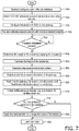
- FIG. 7 illustrates a flowchart 700 of an exemplary processing in accordance with the principles of the invention.
- a set of rules are established in a rules data base at block 710.
- the rules may be preconfigured rules, which are pre-loaded, or may be customization of preconfigured rules, using the user interface, or may be rules that the user creates based on their own conditions.
- the rules may be in the form of "if-then” statements. However, it would be understood that the rules may also be implemented using well known artificial intelligence (AI) techniques (e.g., fuzzy logic) such that actions may be taken even if all the conditions expressed in an "if' statement are not satisfied.
- AI artificial intelligence
- the learning module may weigh the rules such that an appropriate combination of satisfied rules is sufficient to take the corresponding action. For example, in the above example, satisfaction of the three rules (i.e., if conditions) invokes the execution of the two action. In this case, each of the rules is weighted at 100 percent and the intersection of each of the rules is required to satisfy a threshold condition to execute the corresponding actions.
- the rules may be weighted such that the weighted sum of the satisfaction of a plurality of rules (but not all the rules) is sufficient to initiate the corresponding actions.
- the learning module may adapt existing rules based on determined user behavior and/or user inputs to develop additional rules having larger tolerance values, for example.
- sensing units 100 are identified.
- the location and identity of each sensor unit 100 may be determined by a GPS location device and a unique identifier. Or the location of sensing units 100 may be determined based on a relative position with respect to sensing units having a GPS location device.
- each of the identified and located sensing units 100 is configured in the gateway 110, such that the gateway 110 may create a model of the configuration of the sensing units 100 with regard to each HCO.
- the configuration of sensing units 100 is calibrated with regard to individual users.
- a user may provide inputs, using the user interface, regarding their identity, for example. Further information, such as age, weight, height, etc., may be also be inputted to the gateway 110 so that gateway 110 may create a profile containing the user provided information.
- the user provided information may be stored conjunction with information provided by the sensing units 100, as the user is in contact with the sensing units 100 in one or more HCOs.
- the user interface may be interactive, wherein the gateway 110 may enter an interactive mode in which questions are provided to the user. The answers may then be collected with the other user provided information.
- the gateway 110 may first ask a question such as name, and in response to the provided name information, the gateway 100 may ask a second question, such as male or female or age, etc.
- a profile of a user may be formulated that matches identity with distribution patterns.
- information e.g., pressure
- the determination of a pressure being detected may be one of acute (i.e., greater than a threshold) and chronic or persistent (lower than a threshold but persistent for a predetermined time).
- the weight and height of a person activating one or more sensing units 100 may be determined from the information provided by the one or more sensing units 100.
- a distribution pattern of the sensing units 100 providing the detected information is determined.
- the distribution pattern may represent a number of sensing units 100 activated and a pressure (or other characteristic) associated with each of the sensing units 100.
- the determined distribution pattern may then, in one aspect of the invention, be refined to remove sensor information that is not within a mean of the distribution pattern, for example.
- the pressure information and/or distribution pattern may be provided to the gateway 110.
- the gateway 110 may receive individual pressure information of each sensor or from a sensor array 100'. In this case, the gateway 110 may determine the distribution pattern.
- a sensor array 110' may determine the pressure distribution pattern and provide the pressure distribution pattern to the gateway 110.
- the gateway 110 receiving individual measurements and/or distribution pattern collates the received information in order to determine one or more of a location, an identity, a posture and/or a health of a person activating the sensing units 100.
- the measurements and/or distribution pattern received by the gateway 110 may be compared to the inputted data used to create a profile of the users, for example.
- auxiliary devices may comprise lighting, television, radio, window shading, air conditioning, thermostat, etc.
- the information provided by the auxiliary devices may consist of, lighting level, television status or channel, noise level, window shading position, air condition status, room temperature, etc.
- satisfaction of a condition may be probabilistic, wherein a number of features, e.g., weight on HCO, height of resident, distribution pattern(s) may be determined and used to predict a probability of validness of a condition. If the probability is above threshold, e.g., 80%, the condition may be considered valid. In another aspect, an accumulation of conditions that are considered valid may be required to be above a second threshold in order to initiate the corresponding actions.
- learning techniques such as Neural Networks, may be used to assign and adapt the weight of each feature (condition) via a learning mechanism.
- the system may gradually learn new rules based on existing rules and user behavior.
- the actions associated with valid conditions may then be executed when the conditions and/or the accumulated conditions are satisfied.
- new rules may be formulated, or old rules may be altered, as the system iteratively implements actions based on information received from one or more of the sensing units 110.
- a combination of sensing units 100 may be employed in an HCO wherein the sensing units 100 may be one of pressure sensor, an electrode-based sensor, a light or optical based sensor, etc.
- the electrode-based sensors may be selected to provide information regarding measureable events associates with electrocardiograms (EKG), electroencypergrams (ECG), galvanic skin response (GSR) and other similar bio-impedance measurements.
- the light-based sensors may be selected to measure different levels of illumination at a surface, measure different wavelengths, etc.
- the bio-impedance measures may be accumulated and a healthiness of the user may be determined.
- the measurements may be collected and stored.
- an action may further be initiated in response to the bio-impedance measurements considering an identity of a user or resident.
- the specific action may be determined based on at least one rule associated with the user.
- a combination of tactile sensing units 100 and bio-impedance sensing units 100 may be distributed in a HCO, such as a chair or bed.
- the tactile sensors 100 may determine a distribution pattern of a user and based on the distribution pattern may further identify the user, as previously described. Alternatively, the identity of the user may be input to the system. And the distribution pattern used to determine the position of the user.
- the bio-impedance sensing units 100 may collect corresponding information, e.g., heart rate, pulse, that may be used to determine a health of the user.
- information e.g., heart rate, pulse
- the bio-impedance data measurements may be validated in order to determine whether the data measurements are reliable. For example, based on a pressure measured by one or more tactile sensors 100, the bio-impedance measurements may be validated.
- FIG. 8 illustrates an example, system for validating bio-impedance measurement data in accordance with the principles of the invention.
- bio-impedance sensing units 810 and sensing units 100 e.g., tactile sensors
- bio-impedance sensors 840 and sensing units 100 are incorporated into at least one chair arm 825.
- bio-impedance sensors 810 and 840 may be the same or different.
- sensors 810 may be associated with a cardio (e.g., heart rate) measurement
- sensors 840 may be associated with a galvanic measurement.
- sensing units 100 may be used to determine a distribution pattern that may be used to determine a position and/or an identity of a user.
- the bio-impedance sensors 810, 840 may measure corresponding heart rate and galvanic skin response.
- the bio-impedance measures may be compared to expected ranges of measurement and/or previous history information, which has been stored in the user profile.
- the measurements associated with one or more sensing units 100 should exceed a threshold value.
- the position of the user contacting chair back 820 should be substantially the same for each measurement.
- the bio-impedance measurements may be validated.
- a health condition of the user may be determined based on the validated bio-impedance sensor 840 measurements.
- the determined health condition may be compared to expected ranges and/or previously history values associated with the user, to determine an action to be taken.
- a stress condition may be determined. Based on the user identity and the determined stress condition, the lighting surrounding the user may be varied to reduce the determined stress condition. Or calls to doctors or emergency personal may be initiated.
- a threshold e.g., a known percentage
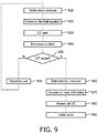
- Figure 9 illustrates a flow chart of an exemplary embodiment of the system configuration shown in Figure 8 .
- measurements from tactile sensing units 100 are collected.
- a distribution pattern based on the measurements associated with the tactile sensing units 100, in each of at least one area, may be determined as previously described.
- An identity of the user may be determined at block 930. The identity of the user may be determined based on the determined distribution pattern or may be input by the user or another person (e.g., a health care professional).
- bio-impedance measurements may be collected.
- a determination may be made whether the distribution pattern in an area corresponding to a desired bio-impedance measurement is valid (e.g., exceeds a threshold value).
- the threshold value may be determined for individuals generally (e.g., male, female, age, etc.), or may be associated with individual users (e.g., stored in a user profile). For example, the threshold values may be determined based on physical characteristics of the user-- height, weight, etc. In one aspect of the invention, the threshold value may be selected differently for distribution pattern areas. The threshold values may be pre-determined based on expected physical characteristics or dynamically determined. The threshold values may be stored in the user profile.
- a current health condition e.g., heart rate variability
- heart rate and heart rate variation data may be collected with an appropriate chose of sensors.
- a distribution pattern may be determined based on a maximum value of the distribution pattern, an average value of the values within the distribution pattern, an average value of the values within the distribution pattern within a known range of the maximum value of the distribution pattern, etc.
- other processes for determining a value for comparing to a threshold value may be formulated without altering the scope of the invention.
- a comparison of the current health condition with at least one of an expected range (based on a characteristic of the identified user, e.g., age, sex) and a previous history data of the identified user is performed.
- a data base is accessed to determine at least one rule associated with the identified user and the determined health condition with regard to the expected ranges and/or previous history data.
- an action associated with the determined rule is performed.
- a generalized rule with regard to the above determined blood pressure may be formulated as:
- a more personalized rule may be formulated as:
- the ID_BLOOD PRESSURE Threshold may be determined based on an age of the user (AGE) or may be determined based on a pass history of similar measurements associated with the identified user. In this latter case, the past history may represent an average value of measurements collected over a known period of time, for example. The threshold value may then be determined based on the average value of the past history values.
- actions resulting from the determined identification and measurements may further include actions such as initiated a new set of measurement data, for example.
- an unacceptable distribution pattern may be determined by comparison of a currently determined distribution pattern with previously collected distribution patterns associated with the user.
- sensing 810, 840, 100 may be incorporated into a bed, wherein validated measurements may be determined when the user is laying on their back and not on their side, for example.
- bio-impedance measurements or other measurements e.g., heart rate, heart rate variation, stress level, etc.
- measurements may be taken when the user is in a correct position to prevent inaccurate measurements from entering the data based.
- a social healthiness of one or more residents may be determined based on information obtained from distributed sensing units 100.
- sensor units 100 incorporated into chairs, sofas, table, etc. may collect data on each of a plurality of residents (or users) sitting on the chairs and sofas, for example.
- distribution patterns based on the sensor information may be determined from each of the plurality of residents.
- an identity of each resident may be determined based on the distribution patterns and a location of each resident may be determined based on the location of the sensor units.
- a proximity graph may then be determined based on the distribution patterns and/or determined locations.
- the proximity graph may then be used to determine a length of time, for example, a pair of identified residents remains in close proximity to each other.
- the length of time may then be used to determine a level of interaction between the pair (or multiple pairs) of identified residents.
- a health status of each of the residents may be monitored during the interaction.
- a determination may be made whether the interaction between the residents is comforting based on collected sensor data associated with heart rate or galvanic response.
- a determination may be made whether the interaction is unsettling based on the collected sensor data.
- tactile sensors such as pressure sensors
- the invention described herein may incorporate multiple sensors that may be used to measure pressure, heat, luminance, etc., in order to provide different types of sensor data that may be used to provide control of the environment surrounding a user or resident.
- the above-described methods according to the present invention can be implemented in hardware, firmware or as software or computer code that can be stored in a recording medium such as a CD ROM, an RAM, a floppy disk, a hard disk, or a magneto-optical disk or computer code downloaded over a network originally stored on a remote recording medium or a non-transitory machine readable medium and to be stored on a local recording medium, so that the methods described herein can be rendered in such software that is stored on the recording medium using a general purpose computer, or a special processor or in programmable or dedicated hardware, such as an ASIC or FPGA.
- a recording medium such as a CD ROM, an RAM, a floppy disk, a hard disk, or a magneto-optical disk or computer code downloaded over a network originally stored on a remote recording medium or a non-transitory machine readable medium and to be stored on a local recording medium, so that the methods described herein can be rendered in such software that is stored on the recording medium using a
- the computer, the processor, microprocessor controller or the programmable hardware include memory components, e.g., RAM, ROM, Flash, etc. that may store or receive software or computer code that when accessed and executed by the computer, processor or hardware implement the processing methods described herein.
- memory components e.g., RAM, ROM, Flash, etc.
- the execution of the code transforms the general purpose computer into a special purpose computer for executing the processing shown herein.
- a computer, a processor and/or dedicated hardware/software are described herein as being capable of performing the processing described herein, and it would be recognized that a computer, a processor and/or dedicated hardware/software are well-known elements in the art of signal processing and, thus, a detailed description of the elements of the processor need not provided in order for one skilled in the art to practice the invention described, herein.
- the terms “comprises”, “comprising”, “includes”, “including”, “has”, “having”, or any other variation thereof, are intended to cover non-exclusive inclusions.
- a process, method, article or apparatus that comprises a list of elements is not necessarily limited to only those elements but may include other elements not expressly listed or inherent to such process, method, article, or apparatus.
- the term “of refers to an inclusive “or” and not to an exclusive “or”.
- a condition A or B is satisfied by any one of the following: A is true (or present) and B is false (or not present); A is false (or not present) and B is true (or present); and both A and B are true (or present).
Landscapes
- Engineering & Computer Science (AREA)
- Computer Networks & Wireless Communication (AREA)
- Automation & Control Theory (AREA)
- Signal Processing (AREA)
- Physics & Mathematics (AREA)
- General Physics & Mathematics (AREA)
- Human Computer Interaction (AREA)
- User Interface Of Digital Computer (AREA)
- Measurement Of The Respiration, Hearing Ability, Form, And Blood Characteristics Of Living Organisms (AREA)
- Circuit Arrangement For Electric Light Sources In General (AREA)
- Measuring And Recording Apparatus For Diagnosis (AREA)
Claims (8)
- Passerelle (110) pour commander au moins un dispositif pouvant être commandé (130), la passerelle (110) étant configurée pour :recevoir des informations en provenance d'au moins une unité de détection tactile (100) incorporée dans au moins un objet de confort domestique, HCO ;formuler un modèle de distribution de pression desdites informations ;identifier un profil d'utilisateur sur la base dudit modèle de distribution de pression ;déterminer une action sur la base dudit profil d'utilisateur identifié et desdites informations reçues, ladite action étant déterminée sur la base de la satisfaction d'au moins une règle parmi une pluralité de règles ; etcommander l'au moins un dispositif pouvant être commandé (130) sur la base de l'action déterminée.
- Système de provisionnement comprenant :au moins une unité de détection tactile (100) incorporée dans l'au moins un objet de confort domestique, HCO ;la passerelle (110) selon la revendication 1 ; etau moins un dispositif pouvant être commandé (130) en réponse à des entrées provenant de ladite passerelle (110), lesdites entrées provenant de ladite passerelle étant déterminées sur la base de l'action déterminée.
- Système selon la revendication 2, dans lequel l'au moins une unité de détection tactile (100) est incorporée dans une surface dudit objet de confort domestique.
- Système selon la revendication 2, dans lequel l'unité de détection tactile (100) est au moins un : d'un capteur tactile, d'un capteur de pression.
- Système selon la revendication 2, dans lequel les informations reçues en provenance des éléments sélectionnés de ladite au moins une unité de détection tactile (100) sont fournies selon l'une : d'une façon continue et d'une façon périodique.
- Système selon la revendication 2, comprenant en outre :
une base de données (330), ladite base de données comprenant ladite pluralité de règles et d'actions associées. - Système selon la revendication 2, dans lequel ledit au moins un dispositif pouvant être commandé (130, 170, 180) comprend au moins l'un : d'un système d'éclairage, d'un dispositif électronique, d'une télévision, d'une radio, d'un obturateur de fenêtre, d'une climatisation et d'un thermostat.
- Système selon la revendication 2, dans lequel la passerelle est en outre configurée pour collationner les informations reçues et pour déterminer une posture et/ou un état de santé d'un utilisateur associé au profil d'utilisateur.
Applications Claiming Priority (2)
| Application Number | Priority Date | Filing Date | Title |
|---|---|---|---|
| US201462055019P | 2014-09-25 | 2014-09-25 | |
| PCT/IB2015/057245 WO2016046718A1 (fr) | 2014-09-25 | 2015-09-21 | Système de gestion de services |
Publications (2)
| Publication Number | Publication Date |
|---|---|
| EP3198577A1 EP3198577A1 (fr) | 2017-08-02 |
| EP3198577B1 true EP3198577B1 (fr) | 2018-07-11 |
Family
ID=54261050
Family Applications (1)
| Application Number | Title | Priority Date | Filing Date |
|---|---|---|---|
| EP15775824.4A Not-in-force EP3198577B1 (fr) | 2014-09-25 | 2015-09-21 | Système de gestion de services |
Country Status (5)
| Country | Link |
|---|---|
| US (1) | US20170230194A1 (fr) |
| EP (1) | EP3198577B1 (fr) |
| JP (1) | JP6679579B2 (fr) |
| CN (1) | CN106716510A (fr) |
| WO (1) | WO2016046718A1 (fr) |
Families Citing this family (10)
| Publication number | Priority date | Publication date | Assignee | Title |
|---|---|---|---|---|
| WO2017216747A1 (fr) | 2016-06-15 | 2017-12-21 | Zyne (Hong Kong) Ltd. | Système d'éclairage à estimation de position et procédé d'estimation de position |
| EP3566548B1 (fr) * | 2017-01-04 | 2020-05-13 | Signify Holding B.V. | Automatisation d'éclairage adaptative |
| RU2654765C1 (ru) * | 2017-06-21 | 2018-05-22 | Акционерное общество "Лётно-исследовательский институт имени М.М. Громова" | Способ определения функционального состояния пилота и система для его осуществления |
| JP7020154B2 (ja) * | 2018-02-02 | 2022-02-16 | 富士フイルムビジネスイノベーション株式会社 | 情報処理システム |
| CN110572895B (zh) * | 2018-06-05 | 2022-12-23 | 松下知识产权经营株式会社 | 子母照明装置、子母照明装置的控制方法及智能照明系统 |
| CN109222934B (zh) * | 2018-10-30 | 2019-06-28 | 北京康加科技有限公司 | 用于生物电阻抗一致性测量的系统及方法 |
| JP7460299B2 (ja) | 2019-04-09 | 2024-04-02 | トヨタホーム株式会社 | 照明設備の制御システム |
| CN112181186A (zh) * | 2019-06-12 | 2021-01-05 | 广东小天才科技有限公司 | 一种基于书写区域辅助补光的方法、智能装置及系统 |
| WO2022164500A1 (fr) * | 2021-01-27 | 2022-08-04 | Karlicek Robert F Jr | Fusion de capteurs destinée à une détection d'occupation à faible puissance |
| CN113598715A (zh) * | 2021-08-18 | 2021-11-05 | 邱超 | 一种智能健康管理设备 |
Family Cites Families (33)
| Publication number | Priority date | Publication date | Assignee | Title |
|---|---|---|---|---|
| JP3340342B2 (ja) * | 1997-02-28 | 2002-11-05 | 株式会社東芝 | テレビジョン選局装置 |
| JP2001061817A (ja) * | 1999-08-27 | 2001-03-13 | Japan Science & Technology Corp | 個人識別方法及び個人識別プログラムを記録した記録媒体 |
| US7552030B2 (en) * | 2002-01-22 | 2009-06-23 | Honeywell International Inc. | System and method for learning patterns of behavior and operating a monitoring and response system based thereon |
| US20060005041A1 (en) * | 2002-09-03 | 2006-01-05 | Koninklijke Philips Electronics N.V. | System for identifying a person |
| JP2009521165A (ja) | 2005-12-22 | 2009-05-28 | コーニンクレッカ フィリップス エレクトロニクス エヌ ヴィ | バレンタイン用の枕状物体 |
| JP2007257088A (ja) * | 2006-03-20 | 2007-10-04 | Univ Of Electro-Communications | ロボット装置及びそのコミュニケーション方法 |
| JP2008257280A (ja) * | 2007-03-30 | 2008-10-23 | Sanyo Electric Co Ltd | 使用者識別装置 |
| JP2008282152A (ja) * | 2007-05-09 | 2008-11-20 | Nippon Telegr & Teleph Corp <Ntt> | 災害予報通報装置および災害予報通報方法 |
| TWI356312B (en) * | 2007-08-22 | 2012-01-11 | Univ Nat Taiwan | Methods and systems for tracking users and providi |
| JP5019603B2 (ja) * | 2007-09-11 | 2012-09-05 | パラマウントベッド株式会社 | 自動照明制御機構 |
| KR20100060457A (ko) * | 2008-11-27 | 2010-06-07 | 삼성전자주식회사 | 이동통신 단말기의 동작모드 제어장치 및 방법 |
| US7882744B2 (en) | 2009-04-14 | 2011-02-08 | Kulite Semiconductor Products, Inc. | Flat planner pressure transducer |
| US8350697B2 (en) * | 2009-05-18 | 2013-01-08 | Alarm.Com Incorporated | Remote device control and energy monitoring by analyzing data and applying rules |
| KR20110050934A (ko) * | 2009-11-09 | 2011-05-17 | 삼성엘이디 주식회사 | 조명 제어 시스템 |
| WO2011115027A1 (fr) * | 2010-03-15 | 2011-09-22 | 日本電気株式会社 | Dispositif de saisie, procédé de saisie et programme |
| US9104211B2 (en) * | 2010-11-19 | 2015-08-11 | Google Inc. | Temperature controller with model-based time to target calculation and display |
| WO2012108834A1 (fr) * | 2011-02-09 | 2012-08-16 | Actatek Pte Ltd | Système et procédé de commande d'appareils électriques |
| WO2012122002A1 (fr) * | 2011-03-04 | 2012-09-13 | Stryker Corporation | Système de détection pour supports de patient |
| JP5908676B2 (ja) * | 2011-03-30 | 2016-04-26 | ソニー株式会社 | 制御装置、制御方法、プログラムおよびシステム |
| DE102011052467B4 (de) * | 2011-08-08 | 2014-12-04 | tado GmbH | Nutzer-zustand und -verhalten basiertes steuerungssystem und -verfahren für gebäudetechnische systeme und komponenten |
| CN102440588B (zh) * | 2011-09-09 | 2013-11-13 | 上海交通大学 | 一种基于坐姿识别的人机交互智能设备的应用 |
| US8964127B2 (en) * | 2012-07-27 | 2015-02-24 | TCL Research America Inc. | User-sensing remote control system and method |
| CN102949051B (zh) * | 2012-11-27 | 2015-10-28 | 北京光华纺织集团有限公司 | 一种智能枕头的用户睡眠信息获得方法及智能枕头 |
| CN103529762B (zh) * | 2013-02-22 | 2016-08-31 | Tcl集团股份有限公司 | 一种基于传感器技术的智能家居控制方法及系统 |
| US9223297B2 (en) * | 2013-02-28 | 2015-12-29 | The Nielsen Company (Us), Llc | Systems and methods for identifying a user of an electronic device |
| CN103202697A (zh) * | 2013-03-18 | 2013-07-17 | 青岛和校生物识别科技有限公司 | 一种可控制的生物信息识别系统 |
| CN203802442U (zh) * | 2013-05-20 | 2014-09-03 | 广东美的制冷设备有限公司 | 检测用户睡眠程度的装置、枕头和空调自适应调节系统 |
| US20150015399A1 (en) * | 2013-07-01 | 2015-01-15 | Geost, Inc. | Providing information related to the posture mode of a user appplying pressure to a seat component |
| US9536056B2 (en) * | 2013-08-30 | 2017-01-03 | Verizon Patent And Licensing Inc. | Method and system of machine-to-machine vertical integration with publisher subscriber architecture |
| CN103544421A (zh) * | 2013-10-16 | 2014-01-29 | 无锡优创生物科技有限公司 | 一种生物特征综合识别系统及方法 |
| WO2015103637A1 (fr) * | 2014-01-06 | 2015-07-09 | Allure Energy, Inc. | Système, dispositif et appareil de coordination d'environnements utilisant des dispositifs de réseau et des informations sensorielles distantes |
| CN103902846A (zh) * | 2014-04-23 | 2014-07-02 | 武汉久乐科技有限公司 | 人体管理服务系统及方法 |
| CN104026921B (zh) * | 2014-05-30 | 2015-09-30 | 南京物联传感技术有限公司 | 具有个人饮用水数据统计的水杯及系统 |
-
2015
- 2015-09-21 US US15/514,603 patent/US20170230194A1/en not_active Abandoned
- 2015-09-21 CN CN201580051954.8A patent/CN106716510A/zh active Pending
- 2015-09-21 WO PCT/IB2015/057245 patent/WO2016046718A1/fr active Application Filing
- 2015-09-21 JP JP2017515887A patent/JP6679579B2/ja not_active Expired - Fee Related
- 2015-09-21 EP EP15775824.4A patent/EP3198577B1/fr not_active Not-in-force
Non-Patent Citations (1)
| Title |
|---|
| None * |
Also Published As
| Publication number | Publication date |
|---|---|
| WO2016046718A1 (fr) | 2016-03-31 |
| CN106716510A (zh) | 2017-05-24 |
| US20170230194A1 (en) | 2017-08-10 |
| JP6679579B2 (ja) | 2020-04-15 |
| EP3198577A1 (fr) | 2017-08-02 |
| JP2017528890A (ja) | 2017-09-28 |
Similar Documents
| Publication | Publication Date | Title |
|---|---|---|
| EP3198577B1 (fr) | Système de gestion de services | |
| US10492721B2 (en) | Method and apparatus for improving and monitoring sleep | |
| US11369321B2 (en) | Monitoring and tracking system, method, article and device | |
| KR102587452B1 (ko) | 생체 정보에 기반하여 장비를 제어하는 기법 | |
| JP7463102B2 (ja) | 人の日常生活動作を監視するためのシステム及び方法 | |
| US11540757B2 (en) | Assessing the functional ability of a person to perform a task | |
| JP2020537263A (ja) | 養護施設及び他の医療施設を運営するための支援技術 | |
| US11116403B2 (en) | Method, apparatus and system for tailoring at least one subsequent communication to a user | |
| JP2019537082A (ja) | ベッド転落を予測及び防止する患者監視のためのデバイス、システム、及び方法 | |
| JP2016101222A (ja) | 入浴システム及びネットワークシステム | |
| JP2017073104A (ja) | 推薦情報を提示する情報処理装置、システム及びプログラム | |
| KR102304877B1 (ko) | 딥러닝 기반의 수면 평가 및 예측을 위한 수면 평가 시스템 | |
| McCullagh et al. | Nocturnal sensing and intervention for assisted living of people with dementia | |
| JP2024500272A (ja) | 病気状態の自動感知用特徴部を有するベッド | |
| CN111726271B (zh) | 起夜情况下的电器配置方法和智能家居系统 | |
| CN110471534B (zh) | 基于情绪识别的信息处理方法及远程医疗管理系统 | |
| KR20190103506A (ko) | 고령자의 건강한 생활 관리를 위한 ai 스피커를 이용한 사물인터넷 기반의 지능형 매트 플랫폼 | |
| CN111008556A (zh) | 智能组合桌椅设备的控制方法 | |
| CN114049928A (zh) | 健康评估方法、健康评估系统及计算机可读存储介质 | |
| WO2023189853A1 (fr) | Procédé et système de détermination d'état de santé | |
| JP7477855B2 (ja) | 情報提供装置、情報提供システム、情報提供方法及び情報提供プログラム | |
| WO2023074283A1 (fr) | Méthode et système de détermination de l'état de santé | |
| WO2023074284A1 (fr) | Procédé de détermination d'état de santé et système de détermination d'état de santé | |
| WO2023217745A1 (fr) | Système et procédé d'évaluation d'un état de santé d'un utilisateur sur la base d'interactions avec des interfaces de commande d'éclairage | |
| CN116072276A (zh) | 医疗设备的参数自适应设置方法及装置、计算机可读存储介质 |
Legal Events
| Date | Code | Title | Description |
|---|---|---|---|
| PUAI | Public reference made under article 153(3) epc to a published international application that has entered the european phase |
Free format text: ORIGINAL CODE: 0009012 |
|
| 17P | Request for examination filed |
Effective date: 20170425 |
|
| AK | Designated contracting states |
Kind code of ref document: A1 Designated state(s): AL AT BE BG CH CY CZ DE DK EE ES FI FR GB GR HR HU IE IS IT LI LT LU LV MC MK MT NL NO PL PT RO RS SE SI SK SM TR |
|
| AX | Request for extension of the european patent |
Extension state: BA ME |
|
| RIN1 | Information on inventor provided before grant (corrected) |
Inventor name: WANG, JIANFENG Inventor name: SHAH, PARIKSHIT Inventor name: WEN, YAO-JUNG Inventor name: NIE, WEIRAN Inventor name: VAN HALTEREN, AART TIJMEN Inventor name: PATEL, MAULIN DAHYABHAI Inventor name: RIISTAMA, JARNO MIKAEL Inventor name: RANGAVAJHALA, SIRISHA |
|
| DAV | Request for validation of the european patent (deleted) | ||
| DAX | Request for extension of the european patent (deleted) | ||
| GRAP | Despatch of communication of intention to grant a patent |
Free format text: ORIGINAL CODE: EPIDOSNIGR1 |
|
| INTG | Intention to grant announced |
Effective date: 20180208 |
|
| GRAS | Grant fee paid |
Free format text: ORIGINAL CODE: EPIDOSNIGR3 |
|
| GRAA | (expected) grant |
Free format text: ORIGINAL CODE: 0009210 |
|
| AK | Designated contracting states |
Kind code of ref document: B1 Designated state(s): AL AT BE BG CH CY CZ DE DK EE ES FI FR GB GR HR HU IE IS IT LI LT LU LV MC MK MT NL NO PL PT RO RS SE SI SK SM TR |
|
| REG | Reference to a national code |
Ref country code: GB Ref legal event code: FG4D |
|
| REG | Reference to a national code |
Ref country code: CH Ref legal event code: EP |
|
| REG | Reference to a national code |
Ref country code: AT Ref legal event code: REF Ref document number: 1017717 Country of ref document: AT Kind code of ref document: T Effective date: 20180715 |
|
| REG | Reference to a national code |
Ref country code: IE Ref legal event code: FG4D |
|
| REG | Reference to a national code |
Ref country code: DE Ref legal event code: R096 Ref document number: 602015013519 Country of ref document: DE |
|
| REG | Reference to a national code |
Ref country code: FR Ref legal event code: PLFP Year of fee payment: 4 |
|
| REG | Reference to a national code |
Ref country code: NL Ref legal event code: MP Effective date: 20180711 |
|
| REG | Reference to a national code |
Ref country code: LT Ref legal event code: MG4D |
|
| RAP2 | Party data changed (patent owner data changed or rights of a patent transferred) |
Owner name: PHILIPS LIGHTING HOLDING B.V. |
|
| REG | Reference to a national code |
Ref country code: AT Ref legal event code: MK05 Ref document number: 1017717 Country of ref document: AT Kind code of ref document: T Effective date: 20180711 |
|
| PG25 | Lapsed in a contracting state [announced via postgrant information from national office to epo] |
Ref country code: NL Free format text: LAPSE BECAUSE OF FAILURE TO SUBMIT A TRANSLATION OF THE DESCRIPTION OR TO PAY THE FEE WITHIN THE PRESCRIBED TIME-LIMIT Effective date: 20180711 |
|
| PG25 | Lapsed in a contracting state [announced via postgrant information from national office to epo] |
Ref country code: GR Free format text: LAPSE BECAUSE OF FAILURE TO SUBMIT A TRANSLATION OF THE DESCRIPTION OR TO PAY THE FEE WITHIN THE PRESCRIBED TIME-LIMIT Effective date: 20181012 Ref country code: AT Free format text: LAPSE BECAUSE OF FAILURE TO SUBMIT A TRANSLATION OF THE DESCRIPTION OR TO PAY THE FEE WITHIN THE PRESCRIBED TIME-LIMIT Effective date: 20180711 Ref country code: NO Free format text: LAPSE BECAUSE OF FAILURE TO SUBMIT A TRANSLATION OF THE DESCRIPTION OR TO PAY THE FEE WITHIN THE PRESCRIBED TIME-LIMIT Effective date: 20181011 Ref country code: IS Free format text: LAPSE BECAUSE OF FAILURE TO SUBMIT A TRANSLATION OF THE DESCRIPTION OR TO PAY THE FEE WITHIN THE PRESCRIBED TIME-LIMIT Effective date: 20181111 Ref country code: PL Free format text: LAPSE BECAUSE OF FAILURE TO SUBMIT A TRANSLATION OF THE DESCRIPTION OR TO PAY THE FEE WITHIN THE PRESCRIBED TIME-LIMIT Effective date: 20180711 Ref country code: RS Free format text: LAPSE BECAUSE OF FAILURE TO SUBMIT A TRANSLATION OF THE DESCRIPTION OR TO PAY THE FEE WITHIN THE PRESCRIBED TIME-LIMIT Effective date: 20180711 Ref country code: FI Free format text: LAPSE BECAUSE OF FAILURE TO SUBMIT A TRANSLATION OF THE DESCRIPTION OR TO PAY THE FEE WITHIN THE PRESCRIBED TIME-LIMIT Effective date: 20180711 Ref country code: SE Free format text: LAPSE BECAUSE OF FAILURE TO SUBMIT A TRANSLATION OF THE DESCRIPTION OR TO PAY THE FEE WITHIN THE PRESCRIBED TIME-LIMIT Effective date: 20180711 Ref country code: LT Free format text: LAPSE BECAUSE OF FAILURE TO SUBMIT A TRANSLATION OF THE DESCRIPTION OR TO PAY THE FEE WITHIN THE PRESCRIBED TIME-LIMIT Effective date: 20180711 Ref country code: BG Free format text: LAPSE BECAUSE OF FAILURE TO SUBMIT A TRANSLATION OF THE DESCRIPTION OR TO PAY THE FEE WITHIN THE PRESCRIBED TIME-LIMIT Effective date: 20181011 |
|
| PG25 | Lapsed in a contracting state [announced via postgrant information from national office to epo] |
Ref country code: LV Free format text: LAPSE BECAUSE OF FAILURE TO SUBMIT A TRANSLATION OF THE DESCRIPTION OR TO PAY THE FEE WITHIN THE PRESCRIBED TIME-LIMIT Effective date: 20180711 Ref country code: AL Free format text: LAPSE BECAUSE OF FAILURE TO SUBMIT A TRANSLATION OF THE DESCRIPTION OR TO PAY THE FEE WITHIN THE PRESCRIBED TIME-LIMIT Effective date: 20180711 Ref country code: HR Free format text: LAPSE BECAUSE OF FAILURE TO SUBMIT A TRANSLATION OF THE DESCRIPTION OR TO PAY THE FEE WITHIN THE PRESCRIBED TIME-LIMIT Effective date: 20180711 |
|
| RAP2 | Party data changed (patent owner data changed or rights of a patent transferred) |
Owner name: SIGNIFY HOLDING B.V. |
|
| REG | Reference to a national code |
Ref country code: DE Ref legal event code: R097 Ref document number: 602015013519 Country of ref document: DE |
|
| PG25 | Lapsed in a contracting state [announced via postgrant information from national office to epo] |
Ref country code: IT Free format text: LAPSE BECAUSE OF FAILURE TO SUBMIT A TRANSLATION OF THE DESCRIPTION OR TO PAY THE FEE WITHIN THE PRESCRIBED TIME-LIMIT Effective date: 20180711 Ref country code: EE Free format text: LAPSE BECAUSE OF FAILURE TO SUBMIT A TRANSLATION OF THE DESCRIPTION OR TO PAY THE FEE WITHIN THE PRESCRIBED TIME-LIMIT Effective date: 20180711 Ref country code: CZ Free format text: LAPSE BECAUSE OF FAILURE TO SUBMIT A TRANSLATION OF THE DESCRIPTION OR TO PAY THE FEE WITHIN THE PRESCRIBED TIME-LIMIT Effective date: 20180711 Ref country code: RO Free format text: LAPSE BECAUSE OF FAILURE TO SUBMIT A TRANSLATION OF THE DESCRIPTION OR TO PAY THE FEE WITHIN THE PRESCRIBED TIME-LIMIT Effective date: 20180711 Ref country code: MC Free format text: LAPSE BECAUSE OF FAILURE TO SUBMIT A TRANSLATION OF THE DESCRIPTION OR TO PAY THE FEE WITHIN THE PRESCRIBED TIME-LIMIT Effective date: 20180711 |
|
| REG | Reference to a national code |
Ref country code: CH Ref legal event code: PL |
|
| PLBE | No opposition filed within time limit |
Free format text: ORIGINAL CODE: 0009261 |
|
| STAA | Information on the status of an ep patent application or granted ep patent |
Free format text: STATUS: NO OPPOSITION FILED WITHIN TIME LIMIT |
|
| PG25 | Lapsed in a contracting state [announced via postgrant information from national office to epo] |
Ref country code: SK Free format text: LAPSE BECAUSE OF FAILURE TO SUBMIT A TRANSLATION OF THE DESCRIPTION OR TO PAY THE FEE WITHIN THE PRESCRIBED TIME-LIMIT Effective date: 20180711 Ref country code: DK Free format text: LAPSE BECAUSE OF FAILURE TO SUBMIT A TRANSLATION OF THE DESCRIPTION OR TO PAY THE FEE WITHIN THE PRESCRIBED TIME-LIMIT Effective date: 20180711 Ref country code: SM Free format text: LAPSE BECAUSE OF FAILURE TO SUBMIT A TRANSLATION OF THE DESCRIPTION OR TO PAY THE FEE WITHIN THE PRESCRIBED TIME-LIMIT Effective date: 20180711 |
|
| REG | Reference to a national code |
Ref country code: BE Ref legal event code: MM Effective date: 20180930 |
|
| 26N | No opposition filed |
Effective date: 20190412 |
|
| REG | Reference to a national code |
Ref country code: IE Ref legal event code: MM4A |
|
| PG25 | Lapsed in a contracting state [announced via postgrant information from national office to epo] |
Ref country code: LU Free format text: LAPSE BECAUSE OF NON-PAYMENT OF DUE FEES Effective date: 20180921 |
|
| PG25 | Lapsed in a contracting state [announced via postgrant information from national office to epo] |
Ref country code: IE Free format text: LAPSE BECAUSE OF NON-PAYMENT OF DUE FEES Effective date: 20180921 Ref country code: ES Free format text: LAPSE BECAUSE OF FAILURE TO SUBMIT A TRANSLATION OF THE DESCRIPTION OR TO PAY THE FEE WITHIN THE PRESCRIBED TIME-LIMIT Effective date: 20180711 |
|
| PG25 | Lapsed in a contracting state [announced via postgrant information from national office to epo] |
Ref country code: CH Free format text: LAPSE BECAUSE OF NON-PAYMENT OF DUE FEES Effective date: 20180930 Ref country code: LI Free format text: LAPSE BECAUSE OF NON-PAYMENT OF DUE FEES Effective date: 20180930 Ref country code: SI Free format text: LAPSE BECAUSE OF FAILURE TO SUBMIT A TRANSLATION OF THE DESCRIPTION OR TO PAY THE FEE WITHIN THE PRESCRIBED TIME-LIMIT Effective date: 20180711 Ref country code: BE Free format text: LAPSE BECAUSE OF NON-PAYMENT OF DUE FEES Effective date: 20180930 |
|
| PG25 | Lapsed in a contracting state [announced via postgrant information from national office to epo] |
Ref country code: MT Free format text: LAPSE BECAUSE OF NON-PAYMENT OF DUE FEES Effective date: 20180921 |
|
| PG25 | Lapsed in a contracting state [announced via postgrant information from national office to epo] |
Ref country code: TR Free format text: LAPSE BECAUSE OF FAILURE TO SUBMIT A TRANSLATION OF THE DESCRIPTION OR TO PAY THE FEE WITHIN THE PRESCRIBED TIME-LIMIT Effective date: 20180711 |
|
| PG25 | Lapsed in a contracting state [announced via postgrant information from national office to epo] |
Ref country code: PT Free format text: LAPSE BECAUSE OF FAILURE TO SUBMIT A TRANSLATION OF THE DESCRIPTION OR TO PAY THE FEE WITHIN THE PRESCRIBED TIME-LIMIT Effective date: 20180711 |
|
| PG25 | Lapsed in a contracting state [announced via postgrant information from national office to epo] |
Ref country code: CY Free format text: LAPSE BECAUSE OF FAILURE TO SUBMIT A TRANSLATION OF THE DESCRIPTION OR TO PAY THE FEE WITHIN THE PRESCRIBED TIME-LIMIT Effective date: 20180711 Ref country code: MK Free format text: LAPSE BECAUSE OF NON-PAYMENT OF DUE FEES Effective date: 20180711 Ref country code: HU Free format text: LAPSE BECAUSE OF FAILURE TO SUBMIT A TRANSLATION OF THE DESCRIPTION OR TO PAY THE FEE WITHIN THE PRESCRIBED TIME-LIMIT; INVALID AB INITIO Effective date: 20150921 |
|
| PGFP | Annual fee paid to national office [announced via postgrant information from national office to epo] |
Ref country code: GB Payment date: 20200925 Year of fee payment: 6 Ref country code: FR Payment date: 20200928 Year of fee payment: 6 Ref country code: DE Payment date: 20200928 Year of fee payment: 6 |
|
| REG | Reference to a national code |
Ref country code: DE Ref legal event code: R119 Ref document number: 602015013519 Country of ref document: DE |
|
| GBPC | Gb: european patent ceased through non-payment of renewal fee |
Effective date: 20210921 |
|
| PG25 | Lapsed in a contracting state [announced via postgrant information from national office to epo] |
Ref country code: GB Free format text: LAPSE BECAUSE OF NON-PAYMENT OF DUE FEES Effective date: 20210921 Ref country code: FR Free format text: LAPSE BECAUSE OF NON-PAYMENT OF DUE FEES Effective date: 20210930 Ref country code: DE Free format text: LAPSE BECAUSE OF NON-PAYMENT OF DUE FEES Effective date: 20220401 |