EP3198044B1 - Controlled deformations in metallic pieces - Google Patents
Controlled deformations in metallic pieces Download PDFInfo
- Publication number
- EP3198044B1 EP3198044B1 EP15777633.7A EP15777633A EP3198044B1 EP 3198044 B1 EP3198044 B1 EP 3198044B1 EP 15777633 A EP15777633 A EP 15777633A EP 3198044 B1 EP3198044 B1 EP 3198044B1
- Authority
- EP
- European Patent Office
- Prior art keywords
- mechanical strength
- piece
- edge
- area
- low mechanical
- Prior art date
- Legal status (The legal status is an assumption and is not a legal conclusion. Google has not performed a legal analysis and makes no representation as to the accuracy of the status listed.)
- Active
Links
- 239000002184 metal Substances 0.000 claims description 42
- 230000000737 periodic effect Effects 0.000 claims description 12
- 238000000034 method Methods 0.000 claims description 9
- 238000004519 manufacturing process Methods 0.000 claims description 3
- 230000008878 coupling Effects 0.000 description 11
- 238000010168 coupling process Methods 0.000 description 11
- 238000005859 coupling reaction Methods 0.000 description 11
- 238000009826 distribution Methods 0.000 description 8
- 229910000734 martensite Inorganic materials 0.000 description 5
- 230000009102 absorption Effects 0.000 description 4
- 238000010521 absorption reaction Methods 0.000 description 4
- 230000008859 change Effects 0.000 description 4
- 238000006073 displacement reaction Methods 0.000 description 4
- 230000035939 shock Effects 0.000 description 4
- 230000007704 transition Effects 0.000 description 4
- 238000011282 treatment Methods 0.000 description 4
- 238000006243 chemical reaction Methods 0.000 description 3
- 230000000052 comparative effect Effects 0.000 description 3
- 230000001276 controlling effect Effects 0.000 description 3
- 238000001816 cooling Methods 0.000 description 3
- 239000000835 fiber Substances 0.000 description 3
- 238000010438 heat treatment Methods 0.000 description 3
- 239000000463 material Substances 0.000 description 3
- 239000013307 optical fiber Substances 0.000 description 3
- 230000001105 regulatory effect Effects 0.000 description 3
- 238000012360 testing method Methods 0.000 description 3
- 230000008901 benefit Effects 0.000 description 2
- 230000006698 induction Effects 0.000 description 2
- 239000000203 mixture Substances 0.000 description 2
- 230000000750 progressive effect Effects 0.000 description 2
- 230000005855 radiation Effects 0.000 description 2
- 230000002787 reinforcement Effects 0.000 description 2
- 238000004088 simulation Methods 0.000 description 2
- 0 *C(CC*1)C=*=C1N Chemical compound *C(CC*1)C=*=C1N 0.000 description 1
- 241000143252 Idaea infirmaria Species 0.000 description 1
- 229910000831 Steel Inorganic materials 0.000 description 1
- 230000001133 acceleration Effects 0.000 description 1
- 229910001566 austenite Inorganic materials 0.000 description 1
- 229910001563 bainite Inorganic materials 0.000 description 1
- 230000000295 complement effect Effects 0.000 description 1
- 230000006835 compression Effects 0.000 description 1
- 238000007906 compression Methods 0.000 description 1
- 238000013016 damping Methods 0.000 description 1
- 230000003247 decreasing effect Effects 0.000 description 1
- 230000010354 integration Effects 0.000 description 1
- 238000013532 laser treatment Methods 0.000 description 1
- 238000012423 maintenance Methods 0.000 description 1
- 238000012986 modification Methods 0.000 description 1
- 230000004048 modification Effects 0.000 description 1
- 238000005457 optimization Methods 0.000 description 1
- 238000013021 overheating Methods 0.000 description 1
- 239000002245 particle Substances 0.000 description 1
- 230000035515 penetration Effects 0.000 description 1
- 235000019362 perlite Nutrition 0.000 description 1
- 239000010451 perlite Substances 0.000 description 1
- 230000003014 reinforcing effect Effects 0.000 description 1
- 238000007493 shaping process Methods 0.000 description 1
- 239000010959 steel Substances 0.000 description 1
- 230000003313 weakening effect Effects 0.000 description 1
- 229910000859 α-Fe Inorganic materials 0.000 description 1
Images


Classifications
-
- C—CHEMISTRY; METALLURGY
- C21—METALLURGY OF IRON
- C21D—MODIFYING THE PHYSICAL STRUCTURE OF FERROUS METALS; GENERAL DEVICES FOR HEAT TREATMENT OF FERROUS OR NON-FERROUS METALS OR ALLOYS; MAKING METAL MALLEABLE, e.g. BY DECARBURISATION OR TEMPERING
- C21D1/00—General methods or devices for heat treatment, e.g. annealing, hardening, quenching or tempering
- C21D1/34—Methods of heating
-
- B—PERFORMING OPERATIONS; TRANSPORTING
- B23—MACHINE TOOLS; METAL-WORKING NOT OTHERWISE PROVIDED FOR
- B23K—SOLDERING OR UNSOLDERING; WELDING; CLADDING OR PLATING BY SOLDERING OR WELDING; CUTTING BY APPLYING HEAT LOCALLY, e.g. FLAME CUTTING; WORKING BY LASER BEAM
- B23K26/00—Working by laser beam, e.g. welding, cutting or boring
- B23K26/0093—Working by laser beam, e.g. welding, cutting or boring combined with mechanical machining or metal-working covered by other subclasses than B23K
-
- C—CHEMISTRY; METALLURGY
- C21—METALLURGY OF IRON
- C21D—MODIFYING THE PHYSICAL STRUCTURE OF FERROUS METALS; GENERAL DEVICES FOR HEAT TREATMENT OF FERROUS OR NON-FERROUS METALS OR ALLOYS; MAKING METAL MALLEABLE, e.g. BY DECARBURISATION OR TEMPERING
- C21D1/00—General methods or devices for heat treatment, e.g. annealing, hardening, quenching or tempering
- C21D1/34—Methods of heating
- C21D1/42—Induction heating
-
- C—CHEMISTRY; METALLURGY
- C21—METALLURGY OF IRON
- C21D—MODIFYING THE PHYSICAL STRUCTURE OF FERROUS METALS; GENERAL DEVICES FOR HEAT TREATMENT OF FERROUS OR NON-FERROUS METALS OR ALLOYS; MAKING METAL MALLEABLE, e.g. BY DECARBURISATION OR TEMPERING
- C21D9/00—Heat treatment, e.g. annealing, hardening, quenching or tempering, adapted for particular articles; Furnaces therefor
- C21D9/0068—Heat treatment, e.g. annealing, hardening, quenching or tempering, adapted for particular articles; Furnaces therefor for particular articles not mentioned below
-
- H—ELECTRICITY
- H05—ELECTRIC TECHNIQUES NOT OTHERWISE PROVIDED FOR
- H05B—ELECTRIC HEATING; ELECTRIC LIGHT SOURCES NOT OTHERWISE PROVIDED FOR; CIRCUIT ARRANGEMENTS FOR ELECTRIC LIGHT SOURCES, IN GENERAL
- H05B6/00—Heating by electric, magnetic or electromagnetic fields
- H05B6/02—Induction heating
- H05B6/10—Induction heating apparatus, other than furnaces, for specific applications
- H05B6/101—Induction heating apparatus, other than furnaces, for specific applications for local heating of metal pieces
-
- C—CHEMISTRY; METALLURGY
- C21—METALLURGY OF IRON
- C21D—MODIFYING THE PHYSICAL STRUCTURE OF FERROUS METALS; GENERAL DEVICES FOR HEAT TREATMENT OF FERROUS OR NON-FERROUS METALS OR ALLOYS; MAKING METAL MALLEABLE, e.g. BY DECARBURISATION OR TEMPERING
- C21D2221/00—Treating localised areas of an article
-
- Y—GENERAL TAGGING OF NEW TECHNOLOGICAL DEVELOPMENTS; GENERAL TAGGING OF CROSS-SECTIONAL TECHNOLOGIES SPANNING OVER SEVERAL SECTIONS OF THE IPC; TECHNICAL SUBJECTS COVERED BY FORMER USPC CROSS-REFERENCE ART COLLECTIONS [XRACs] AND DIGESTS
- Y02—TECHNOLOGIES OR APPLICATIONS FOR MITIGATION OR ADAPTATION AGAINST CLIMATE CHANGE
- Y02P—CLIMATE CHANGE MITIGATION TECHNOLOGIES IN THE PRODUCTION OR PROCESSING OF GOODS
- Y02P10/00—Technologies related to metal processing
- Y02P10/25—Process efficiency
Definitions
- the present invention relates to the field of metal pieces involved in making a metal frame, specifically a frame or a vehicle bodywork.
- the object of the present invention is to provide means for accurately controlling strength characteristics and deformation modes of the metal pieces of this type, during collisions.
- the metal pieces are typically made from a flat metal sheet which is subsequently shaped, typically with heat, in order to obtain a suitable cross section according to said application.
- a particular non-limiting, but preferred, example of a cross section of this type is a generally hat shaped section comprising a bottom portion of the piece extending on both sides by a respective wall that is arranged generally transversal to the bottom, each of the walls extends on its end opposite the bottom of the piece by a flange facing outwards and, in general, typically parallel to the bottom.
- the cross section of these pieces may vary along its length.
- These pieces generally comprise fastening means and mounting interfaces, for example, but not limited to the shape of the fastening holes formed in the flanges.
- stamping tool is shaped so as to limit the areas of contact with the drawn metal blank.
- areas of the metal piece in contact with the cooled stamping tool perform a conversion into a martensitic phase and exhibit a high mechanical strength, for example a tensile strength at least equal to 1300MPa and typically higher than 1400MPa, while areas of the metal piece that are not in direct contact with the stamping tool and thus remain in contact with air, cool down less, perform intermediate phase conversions between the austenitic and martensitic phases and ultimately have a lower mechanical strength, for example a tensile strength less than 1000MPa.
- Such low mechanical strength areas correspond to different compositions, for example a mixture of perlite, ferrite, bainite and annealed martensite.
- Different means may be implemented to prevent too rapid cooling of the piece, and thus to avoid its local hardening.
- Some of these means to prevent rapid cooling of the piece in the stamping tool may consist of recesses or inserts provided in said drawing members or in the form of heating means of specific portions of the drawing members. Examples of such means are disclosed in documents GB 2 313 848 and US 3 703 093 .
- WO 2009/064236 describes making a beam for a motor vehicle bodywork having a body of an essentially martensitic structure with a strength (tensile strength) higher than 1300MPa and a portion near its lower end having a strength (tensile strength) lower than 800MPa, of a width of less than 30mm and not higher than one third of the height of the strut, serving as a transition with a lower fastening end having a essentially martensitic shape.
- document WO 2010/126423 discloses making a piece with three successive adjacent areas of gradually decreasing mechanical strength (tensile strength) lower than 1000MPa.
- document WO 2006/038868 discloses making a piece with a plurality of low mechanical strength areas, for example four low mechanical strength areas, separated in pairs by intermediate higher strength portions.
- WO2014087219 describes a structure for vehicle body front portion including: a front side member; an apron member including an end positioned at a front side of a vehicle with respect to an end of the front side member; a bumper reinforcement including a vehicle width direction outside portion with a first and a second coupling portions; a coupling member that couples the front end of the front side member and the front end of the apron member; an inner energy absorbing portion disposed at the front end of the front side member at a front side of the vehicle; the inner energy absorbing portion coupling the coupling member and the first coupling portion; and an outer energy absorbing portion disposed at the front end of the apron member at a front side of the vehicle; and the outer energy absorbing portion coupling the coupling member and the second coupling portion.
- US2004201256 is related to a crush rail or other structural member of a vehicle provided with crush triggers.
- the crush triggers are formed by heating localized areas of the crush rail or other part and allowing them to cool slowly to provide increased ductility and reduced strength in a localized region.
- WO2011108080 describes a shock absorbing member for absorbing the shock from the front side of a vehicle during a crash.
- the shock absorbing member is positioned between an engine and a vehicle front structure positioned on the front side of the engine, such as on the front side of the radiator. As a consequence, a new path for load is formed between the improve the shock absorption efficiency during a crash.
- US5431445 is related to a vehicle frame including longitudinally extending side rails.
- Each of the side rails has a hollow beam structure and includes a series of sets of corner divots along the corners.
- Each corner divot extends along one side a distance and along an adjacent side a shorter distance.
- the object of the present invention is to provide new means for more accurately controlling a change in the mechanical strength of the metal pieces and modes resulting from the deformation of the metal pieces of this type, during collisions.
- the object of the present invention is to provide a metal piece according to claim 1, having a substantially elongated shape according to a longitudinal direction, for making a motor vehicle, comprising:
- the yield limit is the stress that a material can withstand before a plastic deformation is initiated.
- the tensile strength (ultimate tensile strength) corresponds the maximum stress that a material can withstand before breaking.
- the hardness corresponds to the strength of a material surface to penetration of a harder body, for example, a punch, a log or a durometer tip.
- the at least one area formed through local thermal control of the piece may provide a more accurate control of the mechanical strength of the areas of the metal piece and therewith the deformation behaviour of the piece. Additionally, local ruptures in the metal piece may be avoided in this case.
- At least said area having a mechanical strength lower than the rest of the body of the piece has a yield limit lower than 10% than the rest of the body.
- At least said area having a mechanical strength lower than the rest of the body of the piece has a tensile strength lower than 10% than the rest of the body.
- the hardness of at least said area having a mechanical strength lower than the rest of the body of the piece is lower than 10% than the rest of the body.
- the above mentioned longitudinal direction corresponds to a primary axis of elongation or "primary connecting axis”.
- the lower mechanical strength area undulating along the edge and extends predominantly alternately on each of the walls forming said edge forms a generally periodic pattern undulating along the edge.
- the period of the previously mentioned low mechanical strength patterns may be constant or not.
- the lower mechanical strength area is formed either from a continuous low mechanical strength band or from a series of successive low mechanical strength areas.
- the metal piece of the present invention may comprise a succession of low resistance metal bands distributed along the length of the edge, two successive low mechanical strength bands being separated by a higher mechanical strength intermediate area.
- the piece comprises at least two edges extending in the longitudinal direction, each at the intersection of two respective walls where a common wall between the two edges, and a lower mechanical strength area undulating respectively along each of the two edges extending predominantly alternately on each of the walls forming said shaped edge.
- the patterns of the lower mechanical strength areas undulating on each of the two edges are in phase.
- the patterns undulating on each of the two edges are opposite in phase.
- the portion covered by the lower mechanical strength area has a periodic profile where at least the undulated shape of one edge is selected from the group consisting of sinusoidal, square, triangular or saw tooth.
- the piece comprises at least one additional, lower mechanical strength area formed in a common wall between two edges, between the portions of the interior of each of the two patterns of the low mechanical strength areas extending in said common wall facing one another.
- the piece comprises at least one additional lower mechanical strength area formed in a common wall between two edges and extending transversely so as to connect the portions of the interior of each of the two patterns of low mechanical strength areas extending in said common wall facing one another.
- each pattern of the low mechanical strength area has a half period ranging from 0,2 x b to 1 x b, typically equal to 0,8 x b, wherein b corresponds to the greatest distance between the opposite walls.
- each pattern has a half period different from 0,8 x b, wherein b corresponds to the greatest distance between the opposite walls.
- the lower mechanical strength area undulating along one edge extending predominantly alternately on each of the walls forming said edge extends partially on the two walls located at both sides of a common edge, with a linear distribution according to a section transversal to the primary axis of elongation, alternatively at least 60%, preferably at least 70% in a first wall adjacent the edge and a maximum of 40%, preferably a maximum of 30%, in the second wall adjacent the edge and vice versa.
- edge that defines a wall boundary to determine the aforementioned distribution of at least 60 % and a maximum of 40%, is herein understood to be an imaginary line corresponding to the intersection of two planes corresponding to the outer surfaces of two adjacent sides.
- the low mechanical strength areas cover a linear distribution in a section transversal to the primary axis of elongation, at least 10%, preferably at least 25%, of the width of a wall and a maximum of 80%, preferably a maximum of 60%, of such width.
- edge that defines a wall boundary to determine the aforementioned distribution of at least 10% and a maximum of 80%, is herein understood to be an imaginary line corresponding to the intersection of two planes corresponding to the outer surfaces of two adjacent sides
- the invention also relates to a method according to claim 14 of making a generally elongated metal piece along a longitudinal direction, for the manufacture of a motor vehicle, comprising a step of treating at least one portion of the body of the piece to locally reduce the mechanical strength of an area of the piece to form a low mechanical strength area undulating along one edge extending along one edge extending according to the longitudinal direction to the intersection of two walls of the piece, covering predominantly alternately each of the walls located at both sides of said edge.
- the pieces of the invention are made from a flat metal blank.
- the pieces generally comprise fastening means and mounting interfaces, for example, including, among others, in the shape of fastening holes formed in the flanges.
- the pieces of the invention have at least one low mechanical strength area where the tensile strength is less than 1000MPa as compared to the rest of the piece having a mechanical strength (tensile strength) of at least 1300MPa, preferably higher than 1400MPa, the low mechanical strength area being delimited by a pattern undulating along a longitudinal edge, extending predominantly alternately on each of the two walls forming said edge.
- the pieces have at least one low mechanical strength area whose yield limit is less than 950MPa as compared to the rest of the piece having a yield limit of at least 1000MPa, preferably higher than 1150MPa, the low mechanical strength area being delimited by a pattern undulating along a longitudinal edge extending predominantly alternately on each of the two walls forming said edge.
- the pieces according to the invention illustrated in the figures enclosed herein, have preferably a constant cross section along its length corresponding, for example, to the representation in one of the Figures 1 to 2 enclosed herein.
- the cross section of the pieces may vary along the length of the pieces as shown in Figure 27 .
- the pieces of the invention can be centred on a primary longitudinal axis AA or primary connecting axis, which is rectilinear or not as shown in Figure 28 .
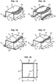
- FIG. 1a One example of a generally hat-shaped piece is shown in Figure 1a enclosed herein, comprising a U-shaped body 12 having a core 10 forming a bottom of the piece and two walls 20, 22 generally orthogonal to the core 10 and forming the walls. Side flanges 30, 32 extend generally orthogonally to the walls 20, 22 and therefore generally parallel to the bottom of the piece 10, outwards.
- the bottom 10 is connected to the walls 20, 22 by their respective edges 11, 13.
- the walls 20, 22 are connected to the flanges 30, 32 through their respective edges 21, 23.
- at least one low mechanical strength area is formed in the piece shown in Figure 1a undulating along at least one of the edges 11, 13, 21 or 23, extending predominantly alternately on each of the walls forming said edge.
- FIG. 1b differs from Figure 1a only by the provision of a cover plate 40 which is supported by and is attached to the flanges 30 and 32 thereby covering the opening of the U-shaped body 12.
- Figure 1c One variant is shown in Figure 1c wherein the piece is a tubular piece comprising, with this example being non limiting, a straight cross section defined by four generally planar walls 10, 20, 22 and 50 respectively parallel and orthogonal in pairs and connected together in pairs by the edges 11, 13, 21 or 23.
- at least one low mechanical strength area is formed in the piece illustrated in Figure 1c undulating along at least one of the edges 11, 13, 21 or 23, predominantly extending alternately on each of the walls forming said edge.
- Figure 2a corresponding to Figure 1c , shows a square cross section with four walls 10, 20, 22 and 50 and thus four edges 11, 13, 21 or 23.
- Figure 2b shows a variant of the tubular piece of this type of hexagonal section comprising six walls 10, 20, 22, 50, 52 and 54 and connected in pairs by six edges 11, 13, 21, 23, 25, 27 and
- Figure 2c shows a further variant of an octagonal tubular piece which comprises eight walls 10, 20, 22, 50, 54, 56 and 58 connected in pairs by eight edges 11, 13, 21, 23, 24, 25, 26 and 27.
- Figure 1d One alternative embodiment is shown in Figure 1d according to which the piece of the present invention is formed by assembling two blanks of the type shown in Figure 1a , mounted facing each other and attached by their flanges in mutual contact in pairs.
- the elements of the two blanks have the same reference numerals as those as in Figure 1a , however they are associated respectively with an a or b index.
- FIG. 1e One alternative embodiment is depicted in Figure 1e according to which a piece is formed by assembling two blanks L comprising two mutually orthogonal walls 10a and 20a, 10b and 20b, respectively, one of the walls 20a, 20b extending outwards through a flange 30a, 30b parallel to the other wall 10a, 10b and being supported by and attached to said other wall 10b, 10a of the piece.
- the walls 10a and 20a, 10b and 20b are respectively connected together by one edge 11a, 11b and the flanges 30a, 30b are connected to the walls 20a, 20b by edges 21a, 21b.
- At least one low mechanical strength area is formed in the piece illustrated in Figure 1e undulating along at least one of the edges 11a, 11b, 21a and 21b extending predominantly alternately on each of the walls forming said shaped edge.
- FIG. 1f differs from Figure 1e by the presence of a displacement or movement 31a, 31b between the bodies of the wall 10a, 10b and the end thereof as it rests on the flange 30b, 30a on one side, wherein the end thus constitutes a second flange 32a, 32b.
- one edge 13a, 13b is formed between the wall body 10a, 10b and the displacement or movement 31a, 31b
- an another edge 23a, 23b is formed between the displacement or movement 31a, 31b and the associated flange 32a, 32b.
- At least one low mechanical strength area is formed in the piece shown in Figure 1f undulating along at least one of the edges 11a, 11b, 21a, 21b, or 13a, 13b, 23a, 23b extending predominantly alternately on each of the walls forming said edge.
- the piece comprises a U-shaped body 12 comprising a core 10 forming a bottom of the piece and two walls 20, 22 substantially orthogonal to the core 10 and forming the walls.
- the bottom of the piece 10 is connected to the walls 20, 22 by their respective edges 11, 13.
- at least one low mechanical strength area is formed in the piece shown in Figure 1g undulating along at least one of the edges 11 or 13 predominantly extending alternately on each of the walls forming said edge.
- the variant illustrated in Figure 1h differs from Figure 1g by the presence of a cover plate 60 covering the opening of the U-shaped body 12.
- the cover plate 60 has a U-shaped geometry with a concavity facing outwards the piece. It is fixed by its side walls on the inner sides of the walls 20, 22 near their free ends.
- the connecting areas 61, 62 between the cover plate 60 and the walls 20, 22 are similar to the edges.
- At least one low mechanical strength area is also formed in the piece shown in Figure 1h undulating along at least one of the edges 11 or 13 or 61, 62 extending predominantly alternately on each of the walls forming said edge.
- the embodiment illustrated in Figure 1i differs from the embodiment illustrated in Figure 1f in that displacements or movements 31a, 31b are replaced by a simple edge 13a, 13b and thereby the flanges 30a, 32b and 30b, 32a are delimited, they do not extend parallel to the bottom of the pieces 10a and 10b as in Figures 1e and 1f , but according to the plane passing through a diagonal of the piece passing through the edges 13a, 13b.
- Figures 3 and 4 illustrate two examples of metal pieces P according to the invention, extending generally according to a longitudinal axis or "primary connecting axis" A and comprises a tubular cross section defined by four generally planar walls 10, 20, 22 and 50, respectively parallel and orthogonal in pairs. Each pair of adjacent walls 10, 20, 22, and 50, defining at their intersection one edge 11, 13, 21, 23 extends generally parallel to the longitudinal axis A, as noted above with respect to Figure 1c .
- Each of the metal pieces P illustrated in Figures 3 and 4 comprises at least one area 100 of a mechanical strength lower than the rest of the body. More specifically, according to the embodiments illustrated in Figures 3 and 4 , four lower mechanical strength areas 100 are formed undulating respectively along each of the edges 11, 13, 21 or 23, extending predominantly alternately on each of the walls 10, 20, 22 and 50 forming said edges 11, 13, 21 or 23.
- the low mechanical resistance areas 100 are formed for example by local thermal control during drawing of the piece P or by other equivalent technique, for example through local thermal control of the piece by applying a laser beam or by induction.
- the low mechanical resistance areas 100 may be selected to change the microstructure e.g. increasing ductility. The selection of the low mechanical resistance areas 100 may be based on crash testing or simulation test although some other methods to select the low mechanical resistance areas 100 may be possible. The low mechanical resistance areas 100 may be defined by simulation in order to determine the most advantageous crash behaviour or better energy absorptions in a simple part e.g. a rail.
- the laser beam (not shown) may be applied onto the selected low mechanical resistance areas 100 using a laser system. In some examples, the laser spot size may be adjusted during the application of the laser beam and it may be adapted to the height and/or width of the low mechanical resistance areas 100, thus the time-consuming change of the optic of the laser system after each application of the laser may be avoided.
- the shape of low mechanical resistance areas 100 may be obtained with only one optic of the laser system, while adjusting the laser spot size.
- the investment in tools may be reduced as well as the maintenance cost.
- the manufacturing time may be reduced as well.
- the variation of the spot may reduce the transition zones at the starting and the final points of the low mechanical resistance areas 100.
- the laser beam may be regulated based on some parameters e.g. temperature measured in the low mechanical resistance areas 100 using a thermometer, e.g. a pyrometer or a camera, to measure high temperatures, thus maintaining the temperature of the laser beam spot.
- a thermometer e.g. a pyrometer or a camera
- the low mechanical resistance areas may be made having different shapes and having different applications e.g. flanges, small or large spots, complex geometric shapes.
- the treatment may be a treatment that locally reduces the mechanical strength of an area of the piece to form the low mechanical strength areas 100, a treatment that locally increases the mechanical strength of the body of the piece except for the desired low mechanical strength areas 100, or a combination of these two types of treatment.
- the metal pieces P thus comprise at least one low mechanical strength area 100 and at least one high mechanical strength area 150 corresponding to the rest of the body.
- the low mechanical strength areas 100 have a low mechanical strength (tensile strength) of less than 1100MPa, typically ranging from 500 to 1000MPa, while the high mechanical strength areas 150 have a mechanical strength (tensile strength) higher than 1100MPa, preferably at least equal to 1300MPa and typically above1400MPa.
- the low mechanical strength areas 100 are formed for example through local control of the drawing temperature of piece P.
- the piece P is heated to a temperature range suitable for obtaining an austenite phase, then it is drawn in a stamping tool adapted to define different temperatures in different areas of the drawn piece, for example through local recesses formed in the stamping tool or by local overheating of the stamping tool.
- the low mechanical strength areas 100 extend along one edge 11, 13, 21 or 23, alternatively on each of the walls 10, 20, 22 and 50 forming said edge, so as to form a generally periodic pattern along said edge.
- the areas 100 are in a periodic sinusoidal arrangement. Thus, they are delimited on the one hand by a rectilinear edge corresponding to a respective edge 11, 13, 21 or 23 and the other hand by a sinusoid undulating at both sides of the edges 11, 13, 21 or 23.
- the invention is not limited to this arrangement. It may be extended to other types of periodic profile.
- Four variants of periodic profiles of the present invention are for example illustrated respectively in Figures 6a, 6b, 6c and 6d , having respectively a sinusoidal, square, triangular or saw tooth shape.
- the patterns of the low mechanical strength areas 100 are arranged continuously extending along edges 11, 13, 21 or 23. According to a diagrammatic embodiment in Figure 13 , the patterns extend discontinuously along the edges 11, 13, 21 or 23. Thus, according to the particular embodiment illustrated in Figure 13 , each band of the low mechanical strength area 100 covers a wave length and a half of the sinusoidal profile and two bands of successive areas 100 are separated by a half wave length.
- the patterns of the low mechanical strength areas 100 under the edges 11, 13, 21 or 23 may be of different periods T.
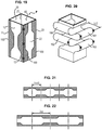
- the half period T/2 of the patterns, ⁇ /2 preferably ranges from 0,2 x b to 1 x b, typically equal to 0,8 x b, wherein b corresponds to the greatest distance between the walls 10 and 50 opposing the piece P as illustrated in Figure 18.
- Figure 18 corresponds to tubular member having a rectangular cross section.
- the distance b corresponds to the greatest distance between a wall and an at least substantially opposite wall.
- the half period T/2 of the patterns may be different from 0,8 x b if, according to the above mentioned particular application, it is desired to force the deformation of the piece according to a step different from the deformation natural step.
- the patterns for the low mechanical strength area 100 have a variable wave length.
- the patterns extending on one wall 10, 20, 22 or 50 are opposite in phase. It is understood that the interiors of the areas 100 provided for example at the edge 21 and of such a polarity in comparison with this edge 21 which are arranged in the wall 50 are respectively facing the interior of the profile provided in the edge 23 which are likewise placed on the same wall 50.
- Interior means herein the portion of the lower mechanical strength profile, the most separated from the associated edge and/or the level at which said low mechanical strength profile is the widest.
- the piece P shown in Figure 3 further comprises additional, lower mechanical strength areas 110 extending on each of the walls 10, 20, 22 and 50 between the portions of the interior of the different patterns extending facing each other on the same wall 10, 20, 22 and 50.
- the additional, lower mechanical strength areas 110 are for example generally disc shaped.
- the additional, lower mechanical strength areas 110 move longitudinally relative to the portions of the interior extending facing each other on the same wall 10, 20, 22 and 50.
- the supplementary low mechanical strength areas 110 of the same wall 10, 20, 22 and 50 are generally aligned parallel to the longitudinal axis A, and extend generally halfway from the portions of the interior extending facing each other on the same wall.
- the patterns extending in the same wall 10, 20, 22 and 50 are opposite in phase.
- the piece P comprises other additional, lower mechanical strength areas 110 extending transversely on each of the walls 10, 20, 22 and 50 so that the portions of the interior of the different patterns are connected to each other, extending facing each other on the same wall 10, 20, 22 and 50, but in the opposite edges 11, 13, 21 or 23.
- the embodiment illustrated in Figure 5 is based on a piece that is shown in Figure 1b (hat-shaped piece and cover plate assembly).
- the patterns of the low mechanical strength areas 100 extending on the same wall 10, 20, 22 and 50, but they are in phase at its opposite edges 11, 13, 21 or 23.
- the interiors of the profile provided for example at the edge 21 and that of such a polarity in comparison with this edge 21 which are arranged in the wall 50 are opposite in phase respectively to the interiors of the profile provided in the opposite edge 23 which are placed in the same way on the same wall 50.
- a low mechanical strength area 100 extends on each of the edges 11, 13, 21 and 23.
- the present invention relates to pieces made of steel.
- Deformation transition areas are formed by the low mechanical strength areas 100 during an axial force on compression allowing the direction of the lateral deformation of the elongated piece P to be oriented, thus preventing random deformation of the pieces.
- the invention allows for example side beam deformation of a cabin to face outwards and not inwards, thereby minimizing impact hazards for cabin occupants.
- the invention allows mainly absorption of energy to be optimized in case of accident.
- curves shown in Figure 7 show that energy absorbed during deformation of a piece according to the invention (curve “A”) is greater than the energy absorbed during deformation of a common piece well-known in the art (curve “B").
- curve B represents the energy absorbed during deformation of a common piece well-known in the art comprising a low mechanical strength area in its entire cross section shown in Figure 9a before deformation and Figure 9b after deformation
- curve A represents the energy absorbed during deformation of a piece according to the invention comprising a low mechanical strength area undulating along one edge, shown in Figure 10a before deformation and Figure 10b after deformation.
- the curve A shows that the energy absorbed by a piece of the present invention is greater, of the order of 65% of the energy absorbed by a piece according to the prior art.
- the invention also allows acceleration peaks experienced by vehicle occupants in case of accident to be reduced.
- Figure 8 illustrates curves that comparatively show the stress generated as a function of the deformation amplitude of the same pieces, showing respectively a curve B of the stress resulting from a common piece well-known in the art comprising a low mechanical strength area in its entire cross section shown in Figure 9a before deformation and Figure 9b after deformation, and in a curve A showing the stress resulting from a piece according to the invention comprising a low mechanical strength area undulating along one edge, shown in Figure 10a before deformation and Figure 10b after deformation.
- metal piece in the context of the present invention is to be understood in a broad sense including both a monobloc structure with no assembly and a structure formed by assembling a plurality of initially individualized entities, but connected by the assembly.
- FIG. 11 An alternative embodiment of the present invention is shown in Figure 11 characterized in that an undulated or periodic profile area with a lower mechanical strength undulating along a single edge 23 is provided.
- Figure 14 depicts one embodiment of a low mechanical strength area 100 undulating in a single edge 11 of a hat-shaped piece illustrated in Figure 1a .
- the two boundary edges of the area 100 have a generally sinusoidal profile except for a local levelling by directrices parallel to the edge 11.
- Figure 15 depicts a further embodiment comprising a low mechanical strength area 100 undulating in each of the four edges 11, 13, 21 and 23 of one piece that is illustrated in Figure 1a .
- Figure 16 represents a variant of Figure 14 adapted to a piece that is illustrated in Figure 1b according to which the low mechanical strength area 100 is discontinuous.
- the metal piece according to the invention comprises a succession of low mechanical strength bands 100 distributed along the length of the edge 11 undulating in both sides, two successive low mechanical strength bands 100 which are separated by an intermediate higher mechanical strength area 102. More specifically, according to the representation shown in Figure 16 , the intermediate area 102 is located between two interior portions of the low mechanical strength area 100 respectively located between the two walls 20 and 50 on both sides of the edge 11.
- Figure 17 shows a variant of Figure 16 applied to a hat-shaped piece illustrated in Figure 1a , where the intermediate, high mechanical area 102 located between two successive low mechanical strength bands 100 is located at the level of the interiors of the low mechanical strength profile.
- Figure 19 represents a tubular piece P comprising low mechanical strength areas 100 undulating along each edge 11, 13, 21 and 23 according to a sinusoidal profile whose period is equal to 0,8xb, while Figure 20 represents deformation obtained from the same piece in a longitudinal tension.
- Figures 19 and 20 when the presence of an area 100 undulating along the edges allows the folds to be arranged alternately on each of the sides of the piece. Indeed, as shown in Figure 20 , by means of this arrangement, the folds protruding outwards the piece are located alternately in the pairs of alternate opposite walls. More specifically, in Figure 20 , external folds 190 and 192 are placed in a wall 10 while external folds 191 and 193 are positioned alternately in an adjacent wall 22.
- Figures 21 and 22 show comparatively low mechanical strength bands according to the invention whose period corresponds to respective multiple ones of a base wave length ⁇ o. More specifically, the length of the low mechanical strength areas 100 shown in Figure 22 is twice the period of the low mechanical strength areas 100 shown in Figure 21 . Typically, but not limited to the period of the areas 100 shown in Figure 21 , it may be equal to period ⁇ o of natural deformations of the piece, a half period of areas 100 equal to the natural half period ⁇ o/2 of the deformation of the piece, while the period of areas 100 shown in Figure 22 is double that of Figure 21 .
- the lower mechanical resistance area 100 undulating along one edge extends predominantly alternately on each of the walls forming said edge extends partially on the two walls on both sides of a common edge, with a linear distribution according to a section transversal to the primary axis of elongation A, at the level of the interior of the patterns, alternatively at least 60%, preferably at least 70%, in a first wall adjacent the edge and a maximum of 40%, preferably at least 30%, in the second wall adjacent the edge at the level of a half period of the low strength pattern, and then conversely for the next half period.
- the low mechanical strength areas 100 cover a linear distribution according to a section transversal to the primary axis of elongation, at least 10%, preferably at least 25%, the width of a wall and a maximum of 80%, preferably a maximum of 60%, of this width. This arrangement allows the deformations to be optimized without weakening the part.
- Figure 26 illustrates an alternative embodiment according to the invention according to which low mechanical strength areas 100 are formed in each series of successive low mechanical strength intervals 100a, 100b, 100C, etc. whose overall contour corresponds to a profile undulating along one edge 23.
- one of the edges of the areas 100 is sinusoidal while the second edge of the areas 100 is rectilinear and corresponds to one edge of the piece.
- the two edges of the areas 100 are generally sinusoidal and equidistant along the length of the pattern, being levelled as necessary by a directrix parallel to the edge as indicated for example in Figure 19 .
- the present invention especially covers low mechanical strength areas 100 corresponding to the following values:
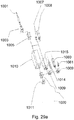
- Figure 29a shows schematically an example of a laser system
- the laser system may have a fiber connector 1003.
- the fiber connector 1003 may be connected at one distal end to an optical fiber 1001.
- the fiber connector 1003 may enable a quick and reliable connection and disconnection to the optical fiber 1001.
- the optical fiber 1001 may act as a guide for the beam of particles and waves.
- a collimating unit 1005 may be provided.
- the collimating unit 1005 may cause the directions of motion of the laser beam to become more aligned in a specific direction.
- the laser system may have a single color pyrometer 1008 although some other alternatives may be possible e.g. two color pyrometer 1007.
- the single color pyrometer 1008 may determine the temperature by measuring the radiation emitted from a surface at one wavelength. In this way, the power of the laser beam may be regulated taking into account the temperature.
- a zoom homogenizer 1010 is also schematically shown.
- the zoom homogenizer may adapt the shape of the laser spot as described later on.
- the zoom homogenizer 1010 may be configured to be connected at the second end to a coupling unit 1020.
- the coupling unit 1020 may be attached to a focusing element 1011.
- the coupling element 1020 may be configured to be provided with an adaptor 1009.
- the adaptor 1009 may attached to a camera 1015 e.g. EMAQS camera.
- the EMAQS camera is a camera-based temperature data acquisition system although some other alternatives are possible e.g. CCD camera 1014.
- the zoom homogenizer 1010 may be configured to be connected to a single color pyrometer 1060 although some other alternatives may be possible e.g. two color pyrometer 1061.
- the single color pyrometer 1060 may determine the temperature by measuring the radiation emitted from a surface at one wavelength. In this way, the power of the laser beam may be regulated taking into account the temperature.
- the laser system may be mounted on a robot (not shown).
- the robot may be mounted on the floor but some other configurations may be possible, e.g. roof mounted.
- the robot may be controlled by control means (not shown).
- An example of a robot that may be that may be employed is the robot IRB 6660 or IRB 760, available from ABB, among others.
- the laser power of the laser system may be limited 20000 W.
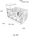
- Fig 29b shows schematically the zoom homogenizer 1010.
- the zoom homogenizer 1010 may transform the beam into a shape e.g. rectangular, circular.
- the zoom homogenizer 1010 may be part of the laser system shown in the figure 29a .
- the zoom homogenizer 1010 may comprise a housing 1038 at least partially enclosing the laser system.
- the housing 1038 may comprise a lens array 1030A, 1030B and 1030C.
- the lens array 1030A, 1030B and 1030C may adjust a spot of the laser beam to the width or length of the different portions of the element scanned during the application of the laser.
- the lens array may implement various focus lines or areas with edges lengths or width up to 180 mm.
- the top-hat energy distribution in the laser focus may be homogenous across the entire setting range, thus the uniform energy input across the entire setting range may be ensured.
- the lens array 1030A, 1030B and 1030C may be designed for laser power outputs up to 20000 W.
- a gear motor 1034 may adjust the size of the laser beam spot acting on the lens array 1030A, 1030B and 1030C.
- the laser beam spot may be motor-adjustable on both axes.
- a plurality of focus sizes and ratios may be implemented using the lens array 1030A, 1030B and 1030C.
- the motorized movement of the lens array 1030A, 1030B and 1030C using the gear motor 1034 may enable the laser beam width or height to be dynamically adjusted.
- the actuation of the gear motor 1034 may enable integration into any machine control system.
- the gear motor 1034 may be attached to a threaded spindle 1033.
- the threaded spindle 1033 may transmit the motion generated by the gear motor 1034.
- the threaded spindle 1033 may have attached at one distal end a spindle nut 1032.
- a motion control unit 1036 may be provided controlling the motion of some of the elements of the zoom homogenizer 1010 e.g. the gear motor 1034.
- the position or velocity of the gear motor 1034 may be controlled using some type of device such as a servo although some other options are possible e.g. a hydraulic pump, linear actuator, or electric motor.
Landscapes
- Chemical & Material Sciences (AREA)
- Engineering & Computer Science (AREA)
- Physics & Mathematics (AREA)
- Mechanical Engineering (AREA)
- Metallurgy (AREA)
- Crystallography & Structural Chemistry (AREA)
- Thermal Sciences (AREA)
- Materials Engineering (AREA)
- Organic Chemistry (AREA)
- Electromagnetism (AREA)
- Optics & Photonics (AREA)
- Plasma & Fusion (AREA)
- Body Structure For Vehicles (AREA)
- Heat Treatment Of Articles (AREA)
- Vibration Dampers (AREA)
- Shaping Metal By Deep-Drawing, Or The Like (AREA)
Applications Claiming Priority (3)
| Application Number | Priority Date | Filing Date | Title |
|---|---|---|---|
| FR1458913A FR3026078A1 (fr) | 2014-09-22 | 2014-09-22 | Piece metallique a orientation de deformations controlees |
| EP14382354.0A EP2998410A1 (en) | 2014-09-22 | 2014-09-22 | Method for laser beam heat treatment of press hardened components and press hardened components |
| PCT/EP2015/071780 WO2016046228A1 (en) | 2014-09-22 | 2015-09-22 | Controlled deformations in metallic pieces |
Publications (2)
| Publication Number | Publication Date |
|---|---|
| EP3198044A1 EP3198044A1 (en) | 2017-08-02 |
| EP3198044B1 true EP3198044B1 (en) | 2020-01-15 |
Family
ID=54266535
Family Applications (1)
| Application Number | Title | Priority Date | Filing Date |
|---|---|---|---|
| EP15777633.7A Active EP3198044B1 (en) | 2014-09-22 | 2015-09-22 | Controlled deformations in metallic pieces |
Country Status (8)
| Country | Link |
|---|---|
| US (1) | US20170292169A1 (enExample) |
| EP (1) | EP3198044B1 (enExample) |
| JP (1) | JP6656257B2 (enExample) |
| KR (1) | KR20170074858A (enExample) |
| BR (1) | BR112017005904A2 (enExample) |
| CA (1) | CA2958020A1 (enExample) |
| ES (1) | ES2778691T3 (enExample) |
| WO (1) | WO2016046228A1 (enExample) |
Families Citing this family (8)
| Publication number | Priority date | Publication date | Assignee | Title |
|---|---|---|---|---|
| JP6044624B2 (ja) * | 2014-12-17 | 2016-12-14 | マツダ株式会社 | 車両用フレーム構造 |
| DE102015215179A1 (de) * | 2015-08-07 | 2017-02-09 | Schwartz Gmbh | Verfahren zur Wärmebehandlung und Wärmebehandlungsvorrichtung |
| RU2681452C1 (ru) * | 2015-10-09 | 2019-03-06 | Ниппон Стил Энд Сумитомо Метал Корпорейшн | Конструктивный элемент и транспортное средство |
| US20180094334A1 (en) * | 2016-09-30 | 2018-04-05 | Lear Corporation | Laser spot hardening |
| JP2019178382A (ja) * | 2018-03-30 | 2019-10-17 | 株式会社ワイテック | 鋼製曲げ成形品の製造方法 |
| JP2022502300A (ja) * | 2018-10-15 | 2022-01-11 | オートテック エンジニアリング エス.エル. | 車両の構造梁のプロファイル |
| JP7120054B2 (ja) * | 2019-01-29 | 2022-08-17 | トヨタ自動車株式会社 | 車両用構造体及び車両用鋼板の強化方法 |
| EP4054777B1 (en) * | 2019-11-08 | 2023-09-13 | Autotech Engineering S.L. | A forming sheet metal part for a vehicle frame and corresponding production method |
Family Cites Families (8)
| Publication number | Priority date | Publication date | Assignee | Title |
|---|---|---|---|---|
| JPH07119892A (ja) * | 1993-10-27 | 1995-05-12 | Nissan Motor Co Ltd | 強度部材 |
| US6820924B2 (en) * | 2003-01-13 | 2004-11-23 | Ford Global Technologies, Llc | Method of improving impact absorbing and deformation control characteristics of vehicle components |
| JP2005178710A (ja) * | 2003-12-24 | 2005-07-07 | Toyota Motor Corp | 衝撃吸収部材 |
| CN101678864B (zh) * | 2007-04-04 | 2012-10-31 | 住友金属工业株式会社 | 汽车车身用强度构件、前纵梁以及汽车车身的侧部构造 |
| US8689955B2 (en) * | 2009-09-14 | 2014-04-08 | Toyota Jidosha Kabushiki Kaisha | Shock absorbing structure |
| WO2012026580A1 (ja) * | 2010-08-26 | 2012-03-01 | 新日本製鐵株式会社 | 衝撃吸収部材 |
| TWI435816B (zh) * | 2010-08-26 | 2014-05-01 | Nippon Steel & Sumitomo Metal Corp | 衝擊吸收構件(一) |
| JP5783261B2 (ja) * | 2011-10-25 | 2015-09-24 | トヨタ自動車株式会社 | 骨格部材 |
-
2015
- 2015-09-22 JP JP2017535142A patent/JP6656257B2/ja not_active Expired - Fee Related
- 2015-09-22 KR KR1020177008535A patent/KR20170074858A/ko not_active Withdrawn
- 2015-09-22 BR BR112017005904A patent/BR112017005904A2/pt not_active Application Discontinuation
- 2015-09-22 EP EP15777633.7A patent/EP3198044B1/en active Active
- 2015-09-22 WO PCT/EP2015/071780 patent/WO2016046228A1/en not_active Ceased
- 2015-09-22 US US15/513,123 patent/US20170292169A1/en not_active Abandoned
- 2015-09-22 ES ES15777633T patent/ES2778691T3/es active Active
- 2015-09-22 CA CA2958020A patent/CA2958020A1/en not_active Abandoned
Non-Patent Citations (1)
| Title |
|---|
| None * |
Also Published As
| Publication number | Publication date |
|---|---|
| CN107208172A (zh) | 2017-09-26 |
| CA2958020A1 (en) | 2016-03-31 |
| ES2778691T3 (es) | 2020-08-11 |
| EP3198044A1 (en) | 2017-08-02 |
| KR20170074858A (ko) | 2017-06-30 |
| US20170292169A1 (en) | 2017-10-12 |
| BR112017005904A2 (pt) | 2017-12-12 |
| JP6656257B2 (ja) | 2020-03-04 |
| JP2017535483A (ja) | 2017-11-30 |
| WO2016046228A1 (en) | 2016-03-31 |
Similar Documents
| Publication | Publication Date | Title |
|---|---|---|
| EP3198044B1 (en) | Controlled deformations in metallic pieces | |
| JP4918491B2 (ja) | 金属シートを熱間スタンプ加工して硬化する方法 | |
| CN105365889B (zh) | 结构组件及结构组件的制造方法 | |
| KR101269339B1 (ko) | 자동차 차체용 강도 부재, 프런트 사이드 멤버 및 자동차 차체의 측부 구조 | |
| JP6417412B2 (ja) | 変形配向の制御された金属部品 | |
| US20110303330A1 (en) | Steel sheet heating device, method for producing press-formed part, and press-formed part | |
| EP3485996B1 (en) | Hot-stamping formed article, structural member using the same, and manufacturing method of hot-stamping formed article | |
| CN105722745A (zh) | 具有u形横截面的横梁 | |
| CN105452093A (zh) | 硬化部件的组件及生产方法 | |
| EP3198043B1 (en) | Method for laser beam heat treatment of press hardened components | |
| JP2009019229A (ja) | 車体閉断面構造部材の製造方法 | |
| US20200346267A1 (en) | Hot stamping formed article and method and device for manufacturing hot stamping formed article | |
| KR20140013103A (ko) | 충격 흡수 부재 | |
| CN107208172B (zh) | 金属工件的可控变形 | |
| CN117500719A (zh) | 用于车辆的结构构件和方法 | |
| KR100467487B1 (ko) | 자동차용 강판의 강성강화 방법 및 그 성형품 | |
| US20230286454A1 (en) | Vehicle bumper | |
| KR101159895B1 (ko) | 프레스 경화용 금형의 냉각장치 및 이에 의한 자동차 부품의 제조방법 | |
| WO2016079272A1 (en) | Beam for producing a metal framework | |
| KR20160077318A (ko) | 구성부재 및 그 제조방법 | |
| KR20240093700A (ko) | 범퍼 빔 |
Legal Events
| Date | Code | Title | Description |
|---|---|---|---|
| STAA | Information on the status of an ep patent application or granted ep patent |
Free format text: STATUS: THE INTERNATIONAL PUBLICATION HAS BEEN MADE |
|
| PUAI | Public reference made under article 153(3) epc to a published international application that has entered the european phase |
Free format text: ORIGINAL CODE: 0009012 |
|
| STAA | Information on the status of an ep patent application or granted ep patent |
Free format text: STATUS: REQUEST FOR EXAMINATION WAS MADE |
|
| 17P | Request for examination filed |
Effective date: 20170424 |
|
| AK | Designated contracting states |
Kind code of ref document: A1 Designated state(s): AL AT BE BG CH CY CZ DE DK EE ES FI FR GB GR HR HU IE IS IT LI LT LU LV MC MK MT NL NO PL PT RO RS SE SI SK SM TR |
|
| AX | Request for extension of the european patent |
Extension state: BA ME |
|
| DAV | Request for validation of the european patent (deleted) | ||
| DAX | Request for extension of the european patent (deleted) | ||
| STAA | Information on the status of an ep patent application or granted ep patent |
Free format text: STATUS: EXAMINATION IS IN PROGRESS |
|
| 17Q | First examination report despatched |
Effective date: 20180514 |
|
| RAP1 | Party data changed (applicant data changed or rights of an application transferred) |
Owner name: AUTOTECH ENGINEERING S.L. |
|
| RIC1 | Information provided on ipc code assigned before grant |
Ipc: C21D 9/00 20060101AFI20190814BHEP Ipc: C21D 1/34 20060101ALI20190814BHEP Ipc: C21D 1/42 20060101ALI20190814BHEP Ipc: B62D 21/15 20060101ALI20190814BHEP Ipc: B60R 19/34 20060101ALI20190814BHEP |
|
| GRAP | Despatch of communication of intention to grant a patent |
Free format text: ORIGINAL CODE: EPIDOSNIGR1 |
|
| STAA | Information on the status of an ep patent application or granted ep patent |
Free format text: STATUS: GRANT OF PATENT IS INTENDED |
|
| INTG | Intention to grant announced |
Effective date: 20190925 |
|
| GRAS | Grant fee paid |
Free format text: ORIGINAL CODE: EPIDOSNIGR3 |
|
| GRAJ | Information related to disapproval of communication of intention to grant by the applicant or resumption of examination proceedings by the epo deleted |
Free format text: ORIGINAL CODE: EPIDOSDIGR1 |
|
| GRAL | Information related to payment of fee for publishing/printing deleted |
Free format text: ORIGINAL CODE: EPIDOSDIGR3 |
|
| STAA | Information on the status of an ep patent application or granted ep patent |
Free format text: STATUS: EXAMINATION IS IN PROGRESS |
|
| GRAR | Information related to intention to grant a patent recorded |
Free format text: ORIGINAL CODE: EPIDOSNIGR71 |
|
| STAA | Information on the status of an ep patent application or granted ep patent |
Free format text: STATUS: GRANT OF PATENT IS INTENDED |
|
| GRAA | (expected) grant |
Free format text: ORIGINAL CODE: 0009210 |
|
| STAA | Information on the status of an ep patent application or granted ep patent |
Free format text: STATUS: THE PATENT HAS BEEN GRANTED |
|
| INTC | Intention to grant announced (deleted) | ||
| INTG | Intention to grant announced |
Effective date: 20191205 |
|
| AK | Designated contracting states |
Kind code of ref document: B1 Designated state(s): AL AT BE BG CH CY CZ DE DK EE ES FI FR GB GR HR HU IE IS IT LI LT LU LV MC MK MT NL NO PL PT RO RS SE SI SK SM TR |
|
| REG | Reference to a national code |
Ref country code: CH Ref legal event code: EP Ref country code: GB Ref legal event code: FG4D |
|
| REG | Reference to a national code |
Ref country code: IE Ref legal event code: FG4D |
|
| REG | Reference to a national code |
Ref country code: DE Ref legal event code: R096 Ref document number: 602015045661 Country of ref document: DE |
|
| REG | Reference to a national code |
Ref country code: AT Ref legal event code: REF Ref document number: 1225190 Country of ref document: AT Kind code of ref document: T Effective date: 20200215 |
|
| REG | Reference to a national code |
Ref country code: NL Ref legal event code: MP Effective date: 20200115 |
|
| REG | Reference to a national code |
Ref country code: LT Ref legal event code: MG4D |
|
| PG25 | Lapsed in a contracting state [announced via postgrant information from national office to epo] |
Ref country code: RS Free format text: LAPSE BECAUSE OF FAILURE TO SUBMIT A TRANSLATION OF THE DESCRIPTION OR TO PAY THE FEE WITHIN THE PRESCRIBED TIME-LIMIT Effective date: 20200115 Ref country code: PT Free format text: LAPSE BECAUSE OF FAILURE TO SUBMIT A TRANSLATION OF THE DESCRIPTION OR TO PAY THE FEE WITHIN THE PRESCRIBED TIME-LIMIT Effective date: 20200607 Ref country code: NO Free format text: LAPSE BECAUSE OF FAILURE TO SUBMIT A TRANSLATION OF THE DESCRIPTION OR TO PAY THE FEE WITHIN THE PRESCRIBED TIME-LIMIT Effective date: 20200415 Ref country code: FI Free format text: LAPSE BECAUSE OF FAILURE TO SUBMIT A TRANSLATION OF THE DESCRIPTION OR TO PAY THE FEE WITHIN THE PRESCRIBED TIME-LIMIT Effective date: 20200115 Ref country code: NL Free format text: LAPSE BECAUSE OF FAILURE TO SUBMIT A TRANSLATION OF THE DESCRIPTION OR TO PAY THE FEE WITHIN THE PRESCRIBED TIME-LIMIT Effective date: 20200115 |
|
| REG | Reference to a national code |
Ref country code: ES Ref legal event code: FG2A Ref document number: 2778691 Country of ref document: ES Kind code of ref document: T3 Effective date: 20200811 |
|
| PG25 | Lapsed in a contracting state [announced via postgrant information from national office to epo] |
Ref country code: SE Free format text: LAPSE BECAUSE OF FAILURE TO SUBMIT A TRANSLATION OF THE DESCRIPTION OR TO PAY THE FEE WITHIN THE PRESCRIBED TIME-LIMIT Effective date: 20200115 Ref country code: LV Free format text: LAPSE BECAUSE OF FAILURE TO SUBMIT A TRANSLATION OF THE DESCRIPTION OR TO PAY THE FEE WITHIN THE PRESCRIBED TIME-LIMIT Effective date: 20200115 Ref country code: HR Free format text: LAPSE BECAUSE OF FAILURE TO SUBMIT A TRANSLATION OF THE DESCRIPTION OR TO PAY THE FEE WITHIN THE PRESCRIBED TIME-LIMIT Effective date: 20200115 Ref country code: GR Free format text: LAPSE BECAUSE OF FAILURE TO SUBMIT A TRANSLATION OF THE DESCRIPTION OR TO PAY THE FEE WITHIN THE PRESCRIBED TIME-LIMIT Effective date: 20200416 Ref country code: BG Free format text: LAPSE BECAUSE OF FAILURE TO SUBMIT A TRANSLATION OF THE DESCRIPTION OR TO PAY THE FEE WITHIN THE PRESCRIBED TIME-LIMIT Effective date: 20200415 Ref country code: IS Free format text: LAPSE BECAUSE OF FAILURE TO SUBMIT A TRANSLATION OF THE DESCRIPTION OR TO PAY THE FEE WITHIN THE PRESCRIBED TIME-LIMIT Effective date: 20200515 |
|
| REG | Reference to a national code |
Ref country code: DE Ref legal event code: R097 Ref document number: 602015045661 Country of ref document: DE |
|
| PG25 | Lapsed in a contracting state [announced via postgrant information from national office to epo] |
Ref country code: CZ Free format text: LAPSE BECAUSE OF FAILURE TO SUBMIT A TRANSLATION OF THE DESCRIPTION OR TO PAY THE FEE WITHIN THE PRESCRIBED TIME-LIMIT Effective date: 20200115 Ref country code: RO Free format text: LAPSE BECAUSE OF FAILURE TO SUBMIT A TRANSLATION OF THE DESCRIPTION OR TO PAY THE FEE WITHIN THE PRESCRIBED TIME-LIMIT Effective date: 20200115 Ref country code: SK Free format text: LAPSE BECAUSE OF FAILURE TO SUBMIT A TRANSLATION OF THE DESCRIPTION OR TO PAY THE FEE WITHIN THE PRESCRIBED TIME-LIMIT Effective date: 20200115 Ref country code: DK Free format text: LAPSE BECAUSE OF FAILURE TO SUBMIT A TRANSLATION OF THE DESCRIPTION OR TO PAY THE FEE WITHIN THE PRESCRIBED TIME-LIMIT Effective date: 20200115 Ref country code: LT Free format text: LAPSE BECAUSE OF FAILURE TO SUBMIT A TRANSLATION OF THE DESCRIPTION OR TO PAY THE FEE WITHIN THE PRESCRIBED TIME-LIMIT Effective date: 20200115 Ref country code: SM Free format text: LAPSE BECAUSE OF FAILURE TO SUBMIT A TRANSLATION OF THE DESCRIPTION OR TO PAY THE FEE WITHIN THE PRESCRIBED TIME-LIMIT Effective date: 20200115 Ref country code: EE Free format text: LAPSE BECAUSE OF FAILURE TO SUBMIT A TRANSLATION OF THE DESCRIPTION OR TO PAY THE FEE WITHIN THE PRESCRIBED TIME-LIMIT Effective date: 20200115 |
|
| PGFP | Annual fee paid to national office [announced via postgrant information from national office to epo] |
Ref country code: DE Payment date: 20200929 Year of fee payment: 6 Ref country code: FR Payment date: 20200925 Year of fee payment: 6 Ref country code: GB Payment date: 20200928 Year of fee payment: 6 |
|
| REG | Reference to a national code |
Ref country code: AT Ref legal event code: MK05 Ref document number: 1225190 Country of ref document: AT Kind code of ref document: T Effective date: 20200115 |
|
| PLBE | No opposition filed within time limit |
Free format text: ORIGINAL CODE: 0009261 |
|
| STAA | Information on the status of an ep patent application or granted ep patent |
Free format text: STATUS: NO OPPOSITION FILED WITHIN TIME LIMIT |
|
| 26N | No opposition filed |
Effective date: 20201016 |
|
| PG25 | Lapsed in a contracting state [announced via postgrant information from national office to epo] |
Ref country code: AT Free format text: LAPSE BECAUSE OF FAILURE TO SUBMIT A TRANSLATION OF THE DESCRIPTION OR TO PAY THE FEE WITHIN THE PRESCRIBED TIME-LIMIT Effective date: 20200115 Ref country code: IT Free format text: LAPSE BECAUSE OF FAILURE TO SUBMIT A TRANSLATION OF THE DESCRIPTION OR TO PAY THE FEE WITHIN THE PRESCRIBED TIME-LIMIT Effective date: 20200115 |
|
| PG25 | Lapsed in a contracting state [announced via postgrant information from national office to epo] |
Ref country code: PL Free format text: LAPSE BECAUSE OF FAILURE TO SUBMIT A TRANSLATION OF THE DESCRIPTION OR TO PAY THE FEE WITHIN THE PRESCRIBED TIME-LIMIT Effective date: 20200115 Ref country code: SI Free format text: LAPSE BECAUSE OF FAILURE TO SUBMIT A TRANSLATION OF THE DESCRIPTION OR TO PAY THE FEE WITHIN THE PRESCRIBED TIME-LIMIT Effective date: 20200115 |
|
| PG25 | Lapsed in a contracting state [announced via postgrant information from national office to epo] |
Ref country code: MC Free format text: LAPSE BECAUSE OF FAILURE TO SUBMIT A TRANSLATION OF THE DESCRIPTION OR TO PAY THE FEE WITHIN THE PRESCRIBED TIME-LIMIT Effective date: 20200115 |
|
| REG | Reference to a national code |
Ref country code: CH Ref legal event code: PL |
|
| REG | Reference to a national code |
Ref country code: BE Ref legal event code: MM Effective date: 20200930 |
|
| PG25 | Lapsed in a contracting state [announced via postgrant information from national office to epo] |
Ref country code: LU Free format text: LAPSE BECAUSE OF NON-PAYMENT OF DUE FEES Effective date: 20200922 |
|
| PG25 | Lapsed in a contracting state [announced via postgrant information from national office to epo] |
Ref country code: BE Free format text: LAPSE BECAUSE OF NON-PAYMENT OF DUE FEES Effective date: 20200930 Ref country code: CH Free format text: LAPSE BECAUSE OF NON-PAYMENT OF DUE FEES Effective date: 20200930 Ref country code: IE Free format text: LAPSE BECAUSE OF NON-PAYMENT OF DUE FEES Effective date: 20200922 Ref country code: LI Free format text: LAPSE BECAUSE OF NON-PAYMENT OF DUE FEES Effective date: 20200930 |
|
| REG | Reference to a national code |
Ref country code: ES Ref legal event code: FD2A Effective date: 20220117 |
|
| REG | Reference to a national code |
Ref country code: DE Ref legal event code: R119 Ref document number: 602015045661 Country of ref document: DE |
|
| GBPC | Gb: european patent ceased through non-payment of renewal fee |
Effective date: 20210922 |
|
| PG25 | Lapsed in a contracting state [announced via postgrant information from national office to epo] |
Ref country code: TR Free format text: LAPSE BECAUSE OF FAILURE TO SUBMIT A TRANSLATION OF THE DESCRIPTION OR TO PAY THE FEE WITHIN THE PRESCRIBED TIME-LIMIT Effective date: 20200115 Ref country code: MT Free format text: LAPSE BECAUSE OF FAILURE TO SUBMIT A TRANSLATION OF THE DESCRIPTION OR TO PAY THE FEE WITHIN THE PRESCRIBED TIME-LIMIT Effective date: 20200115 Ref country code: ES Free format text: LAPSE BECAUSE OF NON-PAYMENT OF DUE FEES Effective date: 20200923 Ref country code: CY Free format text: LAPSE BECAUSE OF FAILURE TO SUBMIT A TRANSLATION OF THE DESCRIPTION OR TO PAY THE FEE WITHIN THE PRESCRIBED TIME-LIMIT Effective date: 20200115 |
|
| PG25 | Lapsed in a contracting state [announced via postgrant information from national office to epo] |
Ref country code: MK Free format text: LAPSE BECAUSE OF FAILURE TO SUBMIT A TRANSLATION OF THE DESCRIPTION OR TO PAY THE FEE WITHIN THE PRESCRIBED TIME-LIMIT Effective date: 20200115 Ref country code: AL Free format text: LAPSE BECAUSE OF FAILURE TO SUBMIT A TRANSLATION OF THE DESCRIPTION OR TO PAY THE FEE WITHIN THE PRESCRIBED TIME-LIMIT Effective date: 20200115 |
|
| PG25 | Lapsed in a contracting state [announced via postgrant information from national office to epo] |
Ref country code: GB Free format text: LAPSE BECAUSE OF NON-PAYMENT OF DUE FEES Effective date: 20210922 Ref country code: FR Free format text: LAPSE BECAUSE OF NON-PAYMENT OF DUE FEES Effective date: 20210930 Ref country code: DE Free format text: LAPSE BECAUSE OF NON-PAYMENT OF DUE FEES Effective date: 20220401 |