EP3197794B1 - Flaschendeckelanordnung mit einziehbarer ausgiesstülle - Google Patents
Flaschendeckelanordnung mit einziehbarer ausgiesstülle Download PDFInfo
- Publication number
- EP3197794B1 EP3197794B1 EP15844195.6A EP15844195A EP3197794B1 EP 3197794 B1 EP3197794 B1 EP 3197794B1 EP 15844195 A EP15844195 A EP 15844195A EP 3197794 B1 EP3197794 B1 EP 3197794B1
- Authority
- EP
- European Patent Office
- Prior art keywords
- spout
- main body
- lid assembly
- flap
- assembly according
- Prior art date
- Legal status (The legal status is an assumption and is not a legal conclusion. Google has not performed a legal analysis and makes no representation as to the accuracy of the status listed.)
- Active
Links
Images


Classifications
-
- B—PERFORMING OPERATIONS; TRANSPORTING
- B65—CONVEYING; PACKING; STORING; HANDLING THIN OR FILAMENTARY MATERIAL
- B65D—CONTAINERS FOR STORAGE OR TRANSPORT OF ARTICLES OR MATERIALS, e.g. BAGS, BARRELS, BOTTLES, BOXES, CANS, CARTONS, CRATES, DRUMS, JARS, TANKS, HOPPERS, FORWARDING CONTAINERS; ACCESSORIES, CLOSURES, OR FITTINGS THEREFOR; PACKAGING ELEMENTS; PACKAGES
- B65D47/00—Closures with filling and discharging, or with discharging, devices
- B65D47/04—Closures with discharging devices other than pumps
- B65D47/06—Closures with discharging devices other than pumps with pouring spouts or tubes; with discharge nozzles or passages
- B65D47/061—Closures with discharging devices other than pumps with pouring spouts or tubes; with discharge nozzles or passages with telescopic, retractable or reversible spouts, tubes or nozzles
-
- B—PERFORMING OPERATIONS; TRANSPORTING
- B65—CONVEYING; PACKING; STORING; HANDLING THIN OR FILAMENTARY MATERIAL
- B65D—CONTAINERS FOR STORAGE OR TRANSPORT OF ARTICLES OR MATERIALS, e.g. BAGS, BARRELS, BOTTLES, BOXES, CANS, CARTONS, CRATES, DRUMS, JARS, TANKS, HOPPERS, FORWARDING CONTAINERS; ACCESSORIES, CLOSURES, OR FITTINGS THEREFOR; PACKAGING ELEMENTS; PACKAGES
- B65D1/00—Rigid or semi-rigid containers having bodies formed in one piece, e.g. by casting metallic material, by moulding plastics, by blowing vitreous material, by throwing ceramic material, by moulding pulped fibrous material or by deep-drawing operations performed on sheet material
- B65D1/02—Bottles or similar containers with necks or like restricted apertures, designed for pouring contents
-
- B—PERFORMING OPERATIONS; TRANSPORTING
- B65—CONVEYING; PACKING; STORING; HANDLING THIN OR FILAMENTARY MATERIAL
- B65D—CONTAINERS FOR STORAGE OR TRANSPORT OF ARTICLES OR MATERIALS, e.g. BAGS, BARRELS, BOTTLES, BOXES, CANS, CARTONS, CRATES, DRUMS, JARS, TANKS, HOPPERS, FORWARDING CONTAINERS; ACCESSORIES, CLOSURES, OR FITTINGS THEREFOR; PACKAGING ELEMENTS; PACKAGES
- B65D47/00—Closures with filling and discharging, or with discharging, devices
- B65D47/04—Closures with discharging devices other than pumps
- B65D47/20—Closures with discharging devices other than pumps comprising hand-operated members for controlling discharge
- B65D47/24—Closures with discharging devices other than pumps comprising hand-operated members for controlling discharge with poppet valves or lift valves, i.e. valves opening or closing a passageway by a relative motion substantially perpendicular to the plane of the seat
- B65D47/241—Closures with discharging devices other than pumps comprising hand-operated members for controlling discharge with poppet valves or lift valves, i.e. valves opening or closing a passageway by a relative motion substantially perpendicular to the plane of the seat the valve being opened or closed by actuating a cap-like element
- B65D47/244—Closures with discharging devices other than pumps comprising hand-operated members for controlling discharge with poppet valves or lift valves, i.e. valves opening or closing a passageway by a relative motion substantially perpendicular to the plane of the seat the valve being opened or closed by actuating a cap-like element being rotated without axial translation, whilst transmitting axial motion to an internal valve stem or valve seat
-
- B—PERFORMING OPERATIONS; TRANSPORTING
- B65—CONVEYING; PACKING; STORING; HANDLING THIN OR FILAMENTARY MATERIAL
- B65D—CONTAINERS FOR STORAGE OR TRANSPORT OF ARTICLES OR MATERIALS, e.g. BAGS, BARRELS, BOTTLES, BOXES, CANS, CARTONS, CRATES, DRUMS, JARS, TANKS, HOPPERS, FORWARDING CONTAINERS; ACCESSORIES, CLOSURES, OR FITTINGS THEREFOR; PACKAGING ELEMENTS; PACKAGES
- B65D47/00—Closures with filling and discharging, or with discharging, devices
- B65D47/04—Closures with discharging devices other than pumps
- B65D47/20—Closures with discharging devices other than pumps comprising hand-operated members for controlling discharge
- B65D47/26—Closures with discharging devices other than pumps comprising hand-operated members for controlling discharge with slide valves, i.e. valves that open and close a passageway by sliding over a port, e.g. formed with slidable spouts
- B65D47/261—Closures with discharging devices other than pumps comprising hand-operated members for controlling discharge with slide valves, i.e. valves that open and close a passageway by sliding over a port, e.g. formed with slidable spouts having a rotational or helicoidal movement
- B65D47/265—Closures with discharging devices other than pumps comprising hand-operated members for controlling discharge with slide valves, i.e. valves that open and close a passageway by sliding over a port, e.g. formed with slidable spouts having a rotational or helicoidal movement between planar parts
Definitions
- the present invention relates to a bottle lid assembly with a retractable spout that can be used for drinking or pouring.
- the invention in one form can be used on a beverage container.
- a very simple form of water bottle includes a spout integrally formed with a bottle.
- the spout has an external thread arranged to engage with a threaded cap.
- lids for bottles have been proposed in the prior art that incorporate an integral spout or straw.
- One such lid assembly is disclosed in US patent 5,244,113 (STYMIEST ), which describes a lid assembly for a container that has both a pour opening and a drinking straw opening. Each opening has a corresponding closure hingedly connected to the lid for sealing the opening. Each closure must be manipulated by the user to move them between the closed and open positions.
- US patent 8,550,269 (LANE ), describes a drink bottle with a removable lid.
- the removable lid includes an inner portion arranged to be attached to the mouth of the bottle and an outer cover pivotably mounted to the inner portion.
- a pliable drinking spout extends from the inner portion and provides a fluid passage from the bottle through said spout.
- the cover is configured to conceal the drinking spout when it is closed and the cover may be locked into the closed position.
- the passage through the pliable drinking spout is closed off when the cover is closed due to the drinking spout being bent over and because of an engagement with a counter ridge formed on the cover.
- a push button release is activated to unlock the cover and to permit it to be pivoted to a position in which the drinking spout is exposed for access by the user.
- US patent 8,469,226 (DAVIES et al. ) , that teaches a cap or lid that includes a mouthpiece assembly configured to be moved between a dispensing position and a stowed position.
- the mouthpiece is biased to the dispensing position and is held in the stowed position by a catch.
- the mouthpiece however is to a degree exposed when in the stowed position unlike the apparatus disclosed in LANE.
- EP Patent 1,477,420 discloses a lid assembly according to the preamble of claim 1.
- the present invention relates to a bottle lid assembly incorporating a spout that is covered by a lid when not in use so as to prevent contamination of the spout and which exposes the spout to the user through the lid upon activation of a mechanism by the user, for example a push button mechanism.
- a lid assembly for a bottle including a base attachable to said bottle over a mouth thereof, a main body rotatably connected to said base, a cover configured to extend over an open upper end of the main body, the cover including an opening extending therethrough, a spout slidably held within said body and movable along a first axis between a retracted position in which the spout is located within the main body and an extended position in which the spout projects through said opening in the cover, wherein said opening in the cover is closed when the spout is in said retracted position, characterised in that a flap is configured to close the opening in the cover when the spout is in said retracted position, and wherein the flap is pivotably mounted to or adjacent said cover and movable in a plane that is generally perpendicular said first axis.
- the main body is configured to rotate relative to the bottle to thereby move the spout between the retracted and extended positions.
- the spout is biased toward an extended position wherein the spout projects out through the opening in the cover.
- a biasing member drives the spout from the retracted position to the extended position.
- the biasing member may be selected from a group containing, but not limited to a helical spring, gas strut, compression spring, torsion spring, constant tension spring or elastomer block.
- Other means for driving the spout from the retracted position to the extended position are also possible, including fully manual rotation, wherein the spout can be moved from the retracted position into the extended position by manual rotation of the main body in one direction and then back into the retracted position by manual rotation of the main body in an opposite direction.
- the spout is preferably held in the retracted position by a releasable latch or mechanism that can be operated by a user to move the spout from the retracted position to the extended position.
- the releasable latch includes some form of release mechanism that can be operated by the user, such as but not limited to, a button, switch or catch.
- the releasable latch may preferably be lockable by a locking member to inhibit inadvertent activation of the release mechanism of said latch.
- the locking member may be in one form a slide member that inhibits operation of the latch.
- the releasable latch is preferably arranged so that it prevents rotation of the main body when in a non-activated condition and allows rotation of the main body when in an activated condition.
- the releasable latch is a push button which is activated by inward pressure by the user, generally towards a vertical centre line extending through the lid assembly.
- the locking member may include a forwardly extending portion that can engage with a slot or indent in the side of the latch to inhibit it from being pushed inward.
- the forwardly extending portion can be disengaged from said slot to permit activation of the latch.
- the main body is preferably arranged to engage with the spout so that under the influence of the biasing member the main body rotates in a first direction upon release or activation of the latch.
- the spout When the main body rotates in the first direction, the spout is able to move along the first axis under the bias of the biasing means.
- the first axis extends generally longitudinally of the length of the bottle.
- Rotation of the main body in a second direction opposite to the first direction, drives the spout along the first axis against the bias of the biasing member.
- rotation in the second direction is affected or caused by the manual rotation of the main body by the user.
- the releasable latch is returned to the non-activated condition to thereby prevent rotation of the main body under the influence of the biasing member.
- At least one inwardly projecting flange or groove is located on or in an inner wall of the main body that engages with protrusions on a side of a spout member.
- the inwardly projecting flange or groove may take the form of a thread member. Although described as being a thread member it should be appreciated that other forms of projections or grooves could be used without departing from the scope of the invention, for instance an oblique or rising shoulder or shoulders could be used to provide the slidable engagement between the main body and the spout member.
- Each flange of the thread member is parallel and angled upwardly and to one side along the longitudinal axis of the main body.
- the spout and main body are engaged together by a flange configuration that could be described as at least one thread.
- the thread is preferably a three start thread and the spout preferably includes three engagement fingers, one for engagement with each start of the thread.
- the fingers are preferably arranged to engage an underside of the thread start and so that the bias of the biasing member tends to drive the fingers upwardly along the underside of the thread.
- the flap is provided to conceal the opening in the cover when the spout is in the retracted, lowermost position.
- the flap is arranged for movement so that the flap can be moved between a first position in which it blocks the opening in the cover and a movement of the spout therethrough.
- the flap rotates about a shaft that has an axis that is parallel to said first axis.
- the flap is preferably substantially located below the lid and over the top of the spout when the spout is in the retracted position.
- the flap is preferably arranged to be driven between the first and second position by rotation of the main body.
- a spur gear member and pinion arrangement is preferably established between the flap and main body to achieve drive of the flap.
- the spur gear member and pinion arrangement is configured to ensure that the flap is opened in a timely manner with respect to movement of the spout along the first axis. This prevents the spout from striking the underside of the flap as it pivots out of the way.
- the spur gear member is located on, or adjacent an inner wall the main body and the pinion is located on a rear or proximal end of the flap adjacent said shaft.
- the dampening assembly may include at least one gear and at least one viscous damper. Other dampening arrangements could also be used.
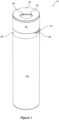
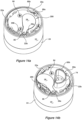
- FIGS 1 to 2b illustrate a bottle lid assembly 10 in accordance with an embodiment of the invention attached to a bottle 100.
- the bottle lid assembly 10 includes a cover 20, a main body 22 and a spout 32.
- the cover 20 includes an opening 26 that can be closed as illustrated in Figure 1 .
- the spout 32 is arranged for movement along a first axis between a retracted position in which it is located within the main body 22 and below the cover 20, and an extended position in which the spout 32 extends through the opening 26 in the cover 20, as illustrated in Figure 2b .
- the first axis extends generally parallel to the longitudinal axis of the lid assembly 10 and a bottle 100.
- the longitudinal axis of the lid assembly 10 with reference to Figure 1 is a vertical axis.
- the lid assembly 10 can be attached to any shape of size of bottle 100, although in the present embodiments the bottle is generally cylindrical. The reader should however appreciate that the shape of the bottle and lid assembly may take other shapes than generally cylindrical.
- Lid assembly 10 further includes a base 24 arranged for connection to the bottle 100.
- the base 24 is arranged for threaded connection to the bottle 100, so that it can be detached for refilling the bottle 100.
- the opening 26 in the cover 20 is closed from below by a flap 28.
- the releasable latch 30 in the present embodiment comprising a push button type mechanism provides a means for triggering the spout 32 to move from the retracted position to the extended position and to thereby move the lid assembly 10 between an open configuration, as illustrated in Figure 2b , and a closed configuration, as illustrated in Figure 1 .
- the flap 28 clears the opening 26, as illustrated in Figure 2a , to enable the spout 32 to move upwardly along the first axis through the opening 26 from the retracted position to the extended position.
- the user can access fluid contained in the bottle 100 via the spout 32.
- locking member 34 is configured to prevent inwardly directed movement of the latch 30 and thus inhibit movement of the lid assembly 10 to the open position. It will of course be appreciated that other forms of locking members are envisaged.
- the locking member 34 is configured to slidably engage the releasable latch 30 to prevent activation thereof, and is slidably held within locking member groove 50.
- main body 22 is formed as a cylindrical tubular member with flanges in the form of a flight or thread 22a located on its inner wall.
- the thread 22a is shown as a three start thread, although other flange, groove or shoulder configurations may be adopted without departing from the scope of the invention.
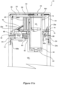
- Main body 22 is formed with gear teeth 22b positioned at an upper end and arranged, in use, to mesh with teeth 28a formed on the flap 28 (see Figures 14a and 14b ).
- Formed in the lower internal wall of the main body 22 is an orientation slot 22c.
- the lower internal wall of the main body 22 also includes a circumferential groove 22d. The function of the orientation slot 22c and the groove 22d will be explained later.
- Each of the portions of the thread 22a includes a stop 22e.
- FIGS. 4a and 4b illustrate the base 24 in more detail.
- the base 24 is moulded as a single piece, although this is not essential and the base may be constructed from a number of integers.
- the base 24 includes connector apertures 24a, a pair of spring posts 40, opening 42, seal button seat 44, annular seal seat 46, push button posts 48, locking member groove 50, ridges 52 and locating pin 54.
- Figure 5 shows a damper 56 mounted on the locating pin 54 between the ridges 52. Ridges 52 located the damper 56 so that it cannot swing on the locating pin 54.
- Locating pin 54 is heat staked down to fix the position of the damper 56 and to prevent it lifting off the locating pin 54, although other ways of fixing are also possible.
- a damper gear 58 is mounted on the damper 56
- a seal button 60 is mounted in the seal button seat 44
- an annular seal 62 is shown mounted on annular seal seat 46, as shown in Figure 10a .
- Damper 56 may adopt different forms but in this instance is a viscous rotary damper.
- the annular seal 62 in the present embodiment is a wiper seal type configuration that maintains sealing contact with the spout 32. As illustrated in Figure 10a the seal 62 is deformed or compressed by the spout 32. The undeformed configuration of the seal 62 is illustrated in the figures by the curved broken line.
- seal 62 is biased against the surface of the spout to inhibit passage of fluid therebetween.
- the wiper seal configuration ensures that there is low friction as the spout extends.
- An advantage with this type of seal is that it works with a lower tolerance housing. The groove inhibits it pulling out as the spout 32 extends and the frictional force tries to drag the seal out of position.
- other configurations of seals could be used without departing from the scope of the invention.
- Figure 6a is a view similar to Figure 5 but shows the additional components of the latch 30 mounted on the push button posts 48, locking member 34 mounted in locking member groove 50, an internal spur gear 64 that engages with cooperating damper gear 58 and a ring bearing 66 mounted thereon, the ring bearing 66 is non-continuous which allows it to be positioned accurately on the seat or race 202 at all times during operation of the lid assembly.
- Figure 6b illustrates the internal spur gear 64.
- spur gear 64 includes teeth 64a, teeth start 64b, locking gap 64c protrusion 64d and bearing seat 202.
- Protrusion 64d is formed in the external periphery of the spur gear 64 and is configured to receive the orientation slot 22c of the main body 22 when the internal spur gear 64 and main body 22 are connected together. The connection between the protrusion 64d and slot 22c ensures that the main body 22 and internal spur gear 64 are properly orientated with respect to each other.
- Teeth 64a of the internal spur gear 64 are arranged to engage with the teeth 59 of the damper gear 58.
- Locking slot 64d is configured so that a detent 30a of the latch 30 can be received therein to lock the spur gear 64 against the bias of the biasing member that would otherwise cause rotation of the main body. This locking action of the latch 30 will be described in more detail later.
- Figure 7 further shows a positioning disc 68, which is arranged for connection to the base 24. Any suitable connectors can be used to secure the positioning disc 68 to the base 24. However, the positioning disc 68 must be secured so that the internal spur gear 64 can rotate with the main body 22 and relative to the positioning disc 68, which is held stationary relative to the base 24 whilst preventing unwanted vertical movement of the internal spur gear 64.
- the positioning disc 68 has a diameter that assists in maintaining the main body 22 in a centralised position by having a close fit.
- Springs 69 are shown mounted on the spring posts 40 and provide the biasing member for this embodiment. The springs 69 are shown in a compressed configuration in Figure 7 .
- Positioning disc 68 includes a main opening 68a, four connector apertures 68b, four feet 68c and three cut-outs 68d intermediate of upstands 68e.
- the connector apertures 68b are provided to enable connectors such as a screw (one of which is shown in Figure 14a ) to be used to connect the positioning disc 68 to the base 24.
- connector apertures 68b are positioned to coaxially align connect apertures 24a in the base 24 and be fixed together by the screws.
- Feet 68c extend from the underside of the positioning disc 68 and are provided to maintain the required spacing between the underside of the positioning disc 68 and the base 24 to enable rotational movement of the internal spur gear 64.
- the feet 68c are dimensioned to prevent downward load exerted onto the positioning disc 68 from being transferred to the spur gear 64 whilst still restricting vertical movement of the positioning disc 68.
- Figures 9a, 9b and 9c illustrate the spout 32.
- the spout 32 includes a body portion 33 incorporating a fluid pathway 70 that is bounded at an upper part 200 by a mouthpiece 74.
- the spout 32 also includes a pair of arms 76 and three fingers 78.
- the fingers 78 are located at about 120° to one another with respect to a central longitudinal axis of the spout 32.
- Each of the arms 76 includes an aperture 79.
- Each aperture 79 is sized so that it can be located over one of the spring posts 40 and so that the lower face of each arm 76 can be positioned during assembly of the lid assembly 10 against an upper face of the positioning disc 68 when the spout 32 is in the retracted position (i.e. with springs 69 compressed).
- the position of the spout 32 in such an arrangement is best shown in Figure 10a .
- the fingers 78 are located within respective cut-outs 68d of the positioning disc 68.
- the spring posts 40 have a lateral cross-sectional profile of generally a cross shape having equal length arms.
- the apertures 79 through the arms 76 of the spout member 32 have a shape that mirrors that of the spring posts 40 but of slightly larger dimensions. This means that the spout member 32 can slide up and down the spring posts 40 with minimal friction.
- the shape of the spring posts 40 and cooperatingly shaped apertures 79 inhibit the spring positioned over a spring post 40 from being caught in the gap between the edge of one of the aperture and the respective spring post.
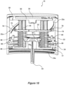
- Figure 10a illustrates the spout 32 in the retracted position within the lid assembly 10.
- the lower face of each arm 76 is shown in contact with the upper face of the positioning disc 68.
- Springs 69 are compressed between the base 24 and the underside of the arms 76 of the spout 32.
- the fingers 78 of the spout 32 bear against the underside of the respective starts of the thread 22a and are held against the underside of the thread 22a by the influence of the springs 69, which helps to remove any slop or play between the spout 32 and main body 22.
- Spout 32 is held in the retracted position against the upward bias of the springs 69 by the detent 30a of the push button 30 which is engaged in the locking gap 64c of the internal spur gear 64.
- the detent 30 is thus engaged, the internal spur gear 64 and connected main body 22 are prevented from rotating and thus the fingers 78 of the spout 32 are locked up against the underside of the starts of the thread 22a.
- the base 24 includes thread 24b (not to be confused with thread 22a in the main body).
- the thread 24b is configured to engage with a correspondingly shaped thread 100a in the bottle 100.
- a seal 77 is positioned between the base 24 and bottle 100 to inhibit leakage.
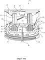
- FIGS 10a to 11c illustrate the relative positioning of the internal spur gear 64, ring bearing 66 and the positioning disc 68.
- Ring bearing 66 sits on a seat or race 202 formed in the upper face of the internal spur gear 64.
- ring bearing 66 is formed as a split ring of circular cross-section.
- Ring bearing 66 is configured to act as a bearing allowing the internal spur gear 64 to rotate (together with the main body 22) relative to the stationary positioning disc 68.
- the ring bearing 66 is preferably made from a low friction, low wear material such as HDPE or nylon or Teflon ® or acetyl and is preferably made of a different material to that of the race or seat 202 in which or on which it sits.
- Damper gear 58 engages with the teeth 64a of the spur gear 64 and rotation of the spur gear 64 is dampened by dampener 56.
- the curvature radius of the race 202 i.e. ring bearing seat
- the curvature radius of a cross-section of the ring bearing 66 so that sliding type line contact is preferably achieved, as opposed to face contact.
- the main sliding face components will be constructed from acetyl, and the base, main body and lid will be constructed from polyester, however the invention is not limited to these materials.
- Figure 10b also clearly depicts how the peripheral edge of the internal spur gear 64 is located within the circumferential groove 22d of the main body 22. This is achieved by a snap type fit once the slot 22c of the main body 22 is vertically aligned with the protrusion 64d of the internal spur gear 64. The lowermost edge of the main body 22 is chamfered to enable the main body 22 to press fit over the internal spur gear 64 to enable the peripheral edge of the spur gear 64 to locate within groove 22d.
- main body 22 is effectively held between the cover 20 and the base 24. This is achieved because the cover 20 is connected to the mounting plate 80, which is connected to the base 24 via the connections to the spring posts 40.
- a small gap 220 is provided between the upper edge of the main body 22 and the underside of the cover 20. This gap 220 enables the main body 22 to rotate relative to the lid 22. Alternatively the underside of the cover 20 can slide across the upper edge of the main body 22 with minimal friction. However this is accomplished the reader will appreciate that the main body 22 is able to rotate relative to the cover 20.
- Mounting plate 80 includes an opening 82 that is arranged in use of the lid assembly 10 to vertically align with the opening 26 formed in the cover 20.
- the opening 82 is of similar dimensions in a horizontal plane to the opening 26, although opening 26 may be larger.
- the opening 82 is bordered on the lower face of the mounting plate 80 with a guide, which as illustrated is formed as three guide segments 83.
- the guide 83 is configured to receive an upper part of the mouthpiece 74 of the spout 32 when the spout 32 is in the retracted position ( Figure 10a ).
- the mounting plate 80 has two apertures 204 through which respective connectors 84 can be passed to connect the mounting plate 80 to the top of respective spring posts 40.
- Screw connectors 84 may be used to establish each of the connections. However, such screw connectors may be replaced with snap on or press fit connectors or any other suitable connection (e.g. a glued connection or welded).
- the mounting plate 80 also includes depending guides 83 that assist with the correct upward movement of the spout 32 as will be discussed later.
- a post 205 is positioned to act as a stop for the flap 28 as it is moved out of the way as illustrated in Figure 14b and so that it is corrected positioned for engagement with the internal spur gear member 22b of the main body 22.
- Mounting plate 80 also acts as a platform for mounting the flap 28 and the cover 20.
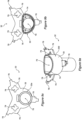
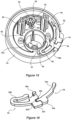
- flap 28 includes a proximal end 206 and a distal end 208.
- the proximal end 206 is formed with a series of gear teeth 28a.
- the gear teeth or pinion 28a are arranged to intermesh with internal spur gear member 22b formed on the internal face of the main body 22 and thus a spur gear and pinion arrangement is established.
- Flap 28 is connected to mounting plate 80 so that the flap 28 can be driven across the plane of the upper face of the mounting plate 80 to move between a first closed position ( Figure 14a ) in which the flap 28 overlies the opening 82 and a second open position ( Figure 14b ) in which it is clear of the opening 82. More particularly, flap 28 is pivotally connected to the mounting plate 80 about a vertical axis extending through post 85. Accordingly, it will be understood that rotational movement of the main body 22 causes the flap 28, through the drive of intermeshed gear teeth 22b, 28a, to pivot about pivot post 85 between the first and second positions. Movement of the flap 28 is timed by the positioning of the spur gear member 22b and pinion 28a arrangement to ensure that the uppermost part of the spout 74 does not strike the underside of the flap 28 whilst the flap 28 is being moved into the second position.
- Cover 20 is arranged for connection to the mounting plate 80.
- simple threaded connectors e.g. screws
- a snap on type connection to the mounting plate 80 is preferred as it eliminates any fixtures or connectors on or through the uppermost face of the cover 20 and thus enhances the appearance of the cover 20.
- cover 20 includes four resilient connectors 20a ( Figure 13 ) extending from its underside. Each connector 20a is arranged to snap fit into a cut-out 80a formed in the mounting plate 80. It will be appreciated that the connection between the cover 20 and mounting plate 80 must be such so as to not impede movement of the flap 28 across the upper face of the mounting plate 80.
- mounting plate 80 is provided with posts 80b, positioned adjacent each cut-out 80a to ensure sufficient spacing between the upper face of the mounting plate 80 and the underside of the lid 20.
- the opening 82 in the mounting plate 80 and the opening 26 in the lid 20 are vertically aligned. It will thus be appreciated that the flap 28 is effective to block a pathway through both of the aligned openings 82, 26.
- the mouthpiece 74 of the spout 32 is arranged to be located within the guide 83 (i.e. the three guide segments 83) formed below the opening 82 of the mounting plate 80 when the spout 32 is in the lowermost position.
- the guides 83 help to direct upward movement of the spout 32 through the aligned openings 82, 26 once the flap 28 is moved to the open position and inhibits it from catching on an edge of the openings 82.
- FIGS 15 to 17b illustrated the releasable latch 30 and locking member 34.
- the latch 30 of the present embodiment includes a detent 30a, a distal end 30b, a push button 30c and a slot 30d.
- the locking member 34 includes an elongate distal end 34a, a grip member 34b and a forwardly extending portion 34c.
- the forwardly extending portion 34c of the locking member 34 can engage with the slot 30d of the latch 30 to inhibit the push button 30c from being pushed inward.
- the forwardly extending portion 34c can be disengaged from the slot 30d to permit activation of the latch 30.
- Latch 30 is formed as a spring clip type configuration and is mounted on the push button post 48 as best shown in Figure 15 .
- Distal end 30b of the push button 30 is located against the wall 42a that defines the opening 42 in the base 24.
- the detent 30a also moves inwardly such that it is clear the locking slot 64d of the internal spur gear 64.
- the internal spur gear 64 is then free to rotate with the main body 22.
- Locking member 34 can be moved to a locked position in which it engages with a slot 30d of the latch 30 thereby preventing inward movement of the push button 30c. Accordingly, when the locking member 34 is in the locked position, latch 30 cannot be activated to release the internal spur gear 64 and therefore the spout 32 is held in the retracted position.
- the internal spur gear 64 with attached main body 22 are free to rotate. Rotation of the main body 22 and the internal spur gear 64 is driven by the bias of the springs 69. More particularly, the springs 69 cause the spout 32 to try to move vertically upwardly in the direction of the cover 20 and along the first axis. However, as the fingers 78 of the spout 32 are engaged with the underside of their respective thread starts 22a, upward movement of the spout 32 causes the main body 22 to rotate. As the main body 22 rotates, the spout 32 is able to move upwardly along the first axis. This upward movement continues until the fingers 78 bear against the underside of mounting plate 80. Each of the thread starts 22a includes a stop 22e, which assists in keeping the components together during assembly of the lid assembly 10.
- the main body 22 is driven to rotate in an anticlockwise direction. This will inhibit a user from inadvertently screwing the lid assembly 10 off the bottle 100 during use, when they are moving the spout into the retracted position.
- the spout 32 When the flap 28 is in the open position, the spout 32 is able to move upwardly through the aligned openings 82, 26 from the retracted position to the extended position.
- the speed of the upward movement of the spout 32 is controlled by the balance between the angle of the threads 22a, the dampening force of the dampener 56 and the bias of the springs 69. Rotation of the main body 22 through about 90 degrees enables the spout 32 to move from the lowermost position to the uppermost position.
- the pitch of the thread 22a on the main body 22 can be varied to alter the angle of rotation of the main body 22 required over which the spout 32 moves between the retracted and extended positions.
- Twisting of the main body 22 by a user in a clockwise direction causes the spout 32 to lower (i.e. to be pushed or driven downwardly against the bias of the springs 69) due to the fingers 78 bearing against the underside of the threads 22a, which thereby caused the flap 28 to close.
- Detent 30a is driven over teeth start 64b of the internal spur gear 64 before locating within the locking gap 64c to prevent further movement of the internal spur gear 64 and thus the attached main body 22.
- the spout 32 moves upwardly to the extended position it further rotates the flap 28 across the face of the mounting plate 80.
- This additional movement or “bump" of the flap 28 beyond the second position may be required to ensure that when the main body 22 is rotated by the user in a clockwise direction to lower the spout 32, the gear teeth 28a of the flap 28 mesh cleanly with the gear teeth 22b formed on the main body 22.
- proper operation of the bottle lid assembly 10 is achieved by appropriate positioning and configuration of the various components. This ensures, for example, that the flap 28 opens in a manner timely to allow the spout 32 to pass through the opening 28 without engaging the underside of the flap 28. Further, that the flap 28 returns to the first position to close the opening 28 when the user manually twists the main body 22.
- Seal 62 seals the connection between the base 24, spout 32 and positioning disc 68. Seal 77 seals the connection between the lid assembly 10 and the bottle 100.
- Embodiments of the present invention are advantageous because the spout is contained within the main body and below the lid when the spout is in the retracted position. Hence, the spout is protected from inadvertent damage and from contamination through contact with other objects.
- the flap prevents dirt and other contaminates reaching the spout when it is in the retracted position.
- a bottle fitted with a lid assembly in accordance with an embodiment of the invention can be safely stored in a hand bag or sports bag.
- Operation of the lid assembly by the user is simple.
- the push of a button reveals the spout to the user.
- the flap moves from the first position to the second position and the spout moves generally vertically upwardly through an opening in the cover with a telescope like motion.
- the user simply rotates the main body which causes the spout to be retracted back into the main body.
- the flap then automatically returns to the first position to close access to the flap.
- the dampened rotation of the main body provides a unique look and feel to the movement of the spout between the retracted and extended positions and also to the rotation of the main body.
- the lid assembly has a clean design and unique appearance.
- the lid assembly can be connected to various different shapes and sizes of bottles.
- the lid assembly can be locked to prevent against inadvertent movement of the spout to the extended position. This ensures that the lid assembly is not accidentally opened to allow fluid to flow through the spout. Hence, the lid assembly will not allow accidental fluid escape when stored in a bag or when the bottle is accidentally knocked over.
Landscapes
- Engineering & Computer Science (AREA)
- Mechanical Engineering (AREA)
- Ceramic Engineering (AREA)
- Closures For Containers (AREA)
- Thermally Insulated Containers For Foods (AREA)
Claims (13)
- Deckelaufbau (10) für eine Flasche (100), einschließendeine Basis (24), die an der Flasche über eine Flaschenöffnung von dieser anbringbar ist,einen Hauptkörper (22), der drehbar mit der Basis verbunden ist,eine Abdeckung (20), die dafür konfiguriert ist, sich über ein offenes oberes Ende des Hauptkörpers zu erstrecken, wobei die Abdeckung eine Öffnung (26) einschließt, die sich durch diese erstreckt,eine Tülle (32), die gleitend innerhalb des Körpers gehalten und entlang einer ersten Achse zwischen einer eingezogenen Position, in der sich die Tülle innerhalb des Hauptkörpers befindet, und einer ausgefahrenen Position, in der die Tülle durch die Öffnung in der Abdeckung ragt, beweglich ist, wobei die Öffnung in der Abdeckung geschlossen ist, wenn sich die Tülle in der eingezogenen Position befindet,wobei eine Klappe (28) dafür konfiguriert ist, die Öffnung in der Abdeckung zu schließen, wenn sich die Tülle in der eingezogenen Position befindet, und wobei die Klappe schwenkbar an der oder neben der Abdeckung montiert ist,dadurch gekennzeichnet, dass die Klappe in einer Ebene beweglich ist, die im Allgemeinen senkrecht zu der ersten Achse ist.
- Deckelaufbau nach Anspruch 1, wobei das Schwenken der Klappe (28) durch Bewegen des Hauptkörpers betätigt wird.
- Deckelaufbau nach einem der vorhergehenden Ansprüche, wobei der Hauptkörper (22) und die Klappe (28) ein internes, geradverzahntes Stirnradelement (22b) und ein Ritzel (28a) einschließen, die zusammenwirken,
wobei während mindestens eines Zeitraums während der Drehung des Hauptkörpers das interne geradverzahnte Stirnradelement mit dem Ritzel in Eingriff kommt, um die Klappe über die Öffnung in der Abdeckung oder von dieser weg zu bewegen. - Deckelaufbau nach einem der vorhergehenden Ansprüche, wobei die Tülle (32) durch ein Vorspannelement von der eingezogenen Position zu der ausgefahrenen Position vorgespannt ist.
- Deckelaufbau nach Anspruch 4, wobei das Vorspannelement eine Schraubenfeder, ein Gasdruckstück, eine Druckfeder, eine Torsionsfeder, eine konstante Spannfeder oder ein Elastomerblock ist.
- Deckelaufbau nach Anspruch 4 oder 5, wobei die Tülle (32) durch einen lösbaren Riegel (30) gegen den Einfluss des Vorspannelements in der eingezogenen Position gehalten wird.
- Deckelaufbau nach Anspruch 6 und ferner einschließend ein Verriegelungselement (34), das dafür konfiguriert ist, eine unbeabsichtigte Aktivierung des lösbaren Riegels zu verhindern.
- Deckelaufbau nach 6 oder 7, wobei beim Lösen des lösbaren Riegels (30) das Vorspannelement auf die Tülle (32) wirkt, um sie in die ausgefahrene Position zu bewegen, wobei die Tülle eine Drehung des Hauptkörpers (22) in eine erste Richtung bewirkt.
- Deckelaufbau nach Anspruch 8, wobei das Drehen des Hauptkörpers (22) in eine zweite Richtung die Tülle (32) entlang der ersten Achse gegen die Vorspannung der Vorspannmittel in die eingezogene Position antreibt.
- Deckelaufbau nach einem der vorhergehenden Ansprüche, wobei die Tülle (32) und der Hauptkörper (22) durch mindestens ein Gewindeelement miteinander im Eingriff stehen.
- Deckelaufbau nach Anspruch 10, wobei das Gewindeelement ein dreigängiges Gewinde ist und die Tülle drei Eingriffsfinger aufweist, einen zum Eingriff mit jedem Gang des Gewindes, wobei jedes der dreigängigen Gewinde einen Anschlag an einem oberen Ende von diesem aufweist, um die Bewegung der Tülle nach oben zu stoppen.
- Deckelaufbau nach einem der vorhergehenden Ansprüche, wobei die Drehung des Hauptkörpers (22) durch ein Dämpfungselement gedämpft wird.
- Flasche (100), einschließend einen Deckelaufbau nach einem der vorhergehenden Ansprüche.
Applications Claiming Priority (2)
| Application Number | Priority Date | Filing Date | Title |
|---|---|---|---|
| AU2014903796A AU2014903796A0 (en) | 2014-09-23 | Bottle lid assembly with drinking spout | |
| PCT/AU2015/050567 WO2016044890A1 (en) | 2014-09-23 | 2015-09-22 | Bottle lid assembly with retractable spout |
Publications (4)
| Publication Number | Publication Date |
|---|---|
| EP3197794A1 EP3197794A1 (de) | 2017-08-02 |
| EP3197794A4 EP3197794A4 (de) | 2018-04-18 |
| EP3197794B1 true EP3197794B1 (de) | 2023-11-01 |
| EP3197794C0 EP3197794C0 (de) | 2023-11-01 |
Family
ID=55579961
Family Applications (1)
| Application Number | Title | Priority Date | Filing Date |
|---|---|---|---|
| EP15844195.6A Active EP3197794B1 (de) | 2014-09-23 | 2015-09-22 | Flaschendeckelanordnung mit einziehbarer ausgiesstülle |
Country Status (7)
| Country | Link |
|---|---|
| US (1) | US10252840B2 (de) |
| EP (1) | EP3197794B1 (de) |
| JP (1) | JP6676044B2 (de) |
| CN (1) | CN107074408B (de) |
| AU (1) | AU2015321422B2 (de) |
| CA (1) | CA2960868C (de) |
| WO (1) | WO2016044890A1 (de) |
Families Citing this family (6)
| Publication number | Priority date | Publication date | Assignee | Title |
|---|---|---|---|---|
| AU201611381S (en) * | 2016-03-11 | 2016-04-27 | Puratap Pty Ltd | Bottle lid |
| CA3053420C (en) | 2017-03-29 | 2024-05-14 | Puratap Pty Ltd | Apparatus and method for measuring fluid consumption |
| AU2018337071B2 (en) * | 2017-09-19 | 2022-09-15 | Puratap Pty Ltd | Spout seal for a container |
| JP6281038B1 (ja) * | 2017-09-25 | 2018-02-14 | 房枝 稲毛 | 飲料用容器 |
| WO2020232498A1 (en) * | 2019-05-22 | 2020-11-26 | Keepcup Pty Ltd | A beverage cup and closure therefor |
| USD929166S1 (en) | 2019-11-26 | 2021-08-31 | Runway Blue, Llc | Straw |
Citations (1)
| Publication number | Priority date | Publication date | Assignee | Title |
|---|---|---|---|---|
| US6102259A (en) * | 1996-02-05 | 2000-08-15 | Tsamourgelis; Ilias | Plastic safety stopper |
Family Cites Families (34)
| Publication number | Priority date | Publication date | Assignee | Title |
|---|---|---|---|---|
| FR1185853A (fr) * | 1957-11-07 | 1959-08-07 | Perfectionnements aux récipients à compression distributeurs de compositions pâteuses | |
| US4183443A (en) * | 1978-08-25 | 1980-01-15 | Billitzer Edward P | Reusable cup cover |
| GB2088838B (en) * | 1980-10-28 | 1984-09-12 | Drdlik Frank | Closures for containers |
| JPS5829951U (ja) * | 1981-08-21 | 1983-02-26 | 紀伊産業株式会社 | 容器キヤツプ |
| JPH0137236Y2 (de) | 1985-02-08 | 1989-11-10 | ||
| JPH0451188Y2 (de) * | 1986-07-09 | 1992-12-02 | ||
| JPH0449096Y2 (de) * | 1986-08-15 | 1992-11-18 | ||
| FR2644432B2 (fr) * | 1988-05-11 | 1991-06-14 | Morel Simone | Capsule a enveloppe tournante pour flacons et recipients analogues |
| JPH0369465A (ja) * | 1989-08-03 | 1991-03-25 | Shiyouhei Akizuki | 瓶型容器の組立自在蓋 |
| US5244113A (en) * | 1992-08-24 | 1993-09-14 | Northwestern Bottle Company | Container lid assembly |
| JPH06273825A (ja) * | 1993-03-22 | 1994-09-30 | Canon Inc | バリア機構を設けたカメラ |
| US5282541A (en) * | 1993-05-17 | 1994-02-01 | Chen Wen Yen | Cap locking device for a water bottle |
| IT1276921B1 (it) * | 1995-10-12 | 1997-11-03 | Capsol S R L Ora Capsol S P A | Cappuccio con mantello girevole per versare sostanze fluide |
| US6332551B1 (en) * | 1998-11-10 | 2001-12-25 | Stephan Copeland | Self-sealing container |
| US6010029A (en) * | 1998-11-27 | 2000-01-04 | Wang; Jung-Liang | Container lid assembly |
| US8393487B1 (en) * | 2000-01-06 | 2013-03-12 | Pacific Market International, Llc | Hygienic twist lid for insulated beverage container |
| US6626314B1 (en) * | 2001-03-13 | 2003-09-30 | Rexam Beverage Can Company | Resealable closure for beverage container |
| US6814267B2 (en) * | 2002-04-02 | 2004-11-09 | Hopkins Manufacturing Corporation | Flow control device for large capacity container |
| US7189134B2 (en) * | 2002-11-18 | 2007-03-13 | In Zone, Inc. | Interactive beverage bottle top |
| FR2851896B1 (fr) * | 2003-03-07 | 2005-04-22 | Oreal | Boitier de conditionnement d'un produit a ouverture amortie |
| EP1477420A1 (de) * | 2003-05-14 | 2004-11-17 | L&M SERVICES B.V. | Verschluss mit Ausgiestülle |
| US7093735B2 (en) * | 2003-08-22 | 2006-08-22 | William Stephens | Drinking vessel with retractable straw |
| CN1926028A (zh) * | 2004-01-13 | 2007-03-07 | Bound2B有限公司 | 用于密封食品容器的装置以及带有这种装置的食品容器 |
| US20060180585A1 (en) * | 2004-12-29 | 2006-08-17 | Rubbermaid Incorporated | Twist up spout for beverage container |
| JP4970016B2 (ja) * | 2006-12-12 | 2012-07-04 | 大王製紙株式会社 | 蓋体の開閉構造 |
| US8544676B2 (en) * | 2008-04-03 | 2013-10-01 | Cool Gear International, Llc | System for use with a consumable beverage |
| CN201268440Y (zh) * | 2008-08-12 | 2009-07-08 | 上海宏晨家庭用品有限公司 | 滑销式防误开容器盖 |
| US20100108724A1 (en) * | 2008-10-30 | 2010-05-06 | Gilbert Buchalter | Twist open/twist close Closure |
| US8191727B2 (en) * | 2009-01-21 | 2012-06-05 | Camelbak Products, Llc | Drink containers |
| WO2010123382A1 (en) * | 2009-04-21 | 2010-10-28 | Sistema Plastics Limited | Dispensing closure assemblies ("spring twist") |
| US8360258B2 (en) * | 2010-11-15 | 2013-01-29 | Pacific Market International, Llc | Beverage container closure |
| US8550269B2 (en) * | 2011-06-08 | 2013-10-08 | Thermos L.L.C. | Drink bottle and lid with cover for drink spout |
| US20130153085A1 (en) * | 2011-12-16 | 2013-06-20 | Don Shefler | Multi-compartment beverage container |
| WO2016070234A1 (en) * | 2014-11-07 | 2016-05-12 | Think One Pty Ltd | Container with press button opening |
-
2015
- 2015-09-22 EP EP15844195.6A patent/EP3197794B1/de active Active
- 2015-09-22 WO PCT/AU2015/050567 patent/WO2016044890A1/en not_active Ceased
- 2015-09-22 CA CA2960868A patent/CA2960868C/en active Active
- 2015-09-22 US US15/512,374 patent/US10252840B2/en active Active
- 2015-09-22 JP JP2017516136A patent/JP6676044B2/ja active Active
- 2015-09-22 CN CN201580050097.XA patent/CN107074408B/zh active Active
- 2015-09-22 AU AU2015321422A patent/AU2015321422B2/en active Active
Patent Citations (1)
| Publication number | Priority date | Publication date | Assignee | Title |
|---|---|---|---|---|
| US6102259A (en) * | 1996-02-05 | 2000-08-15 | Tsamourgelis; Ilias | Plastic safety stopper |
Also Published As
| Publication number | Publication date |
|---|---|
| NZ730643A (en) | 2022-03-25 |
| AU2015321422B2 (en) | 2020-02-20 |
| US20170275061A1 (en) | 2017-09-28 |
| EP3197794A4 (de) | 2018-04-18 |
| CN107074408A (zh) | 2017-08-18 |
| CA2960868C (en) | 2023-03-14 |
| JP6676044B2 (ja) | 2020-04-08 |
| EP3197794C0 (de) | 2023-11-01 |
| EP3197794A1 (de) | 2017-08-02 |
| CN107074408B (zh) | 2019-03-08 |
| AU2015321422A1 (en) | 2017-04-20 |
| US10252840B2 (en) | 2019-04-09 |
| CA2960868A1 (en) | 2016-03-31 |
| WO2016044890A1 (en) | 2016-03-31 |
| JP2017530065A (ja) | 2017-10-12 |
Similar Documents
| Publication | Publication Date | Title |
|---|---|---|
| EP3197794B1 (de) | Flaschendeckelanordnung mit einziehbarer ausgiesstülle | |
| US9944438B2 (en) | Cap adapted to engage container with another object | |
| EP3009053A1 (de) | Deckelanordnung und trinkbehälter damit | |
| US7753234B1 (en) | Fluid container closure mechanism with detachable valve assembly | |
| US20120024815A1 (en) | Container with anti-loss and anti-idle-rotation cap | |
| CN102171108B (zh) | 具有内部件和外部件的容器盖 | |
| RU2481259C2 (ru) | Нажимно-вытяжной затвор для емкости для питья | |
| JP6608373B2 (ja) | 開栓明示機能を有するクロージャ | |
| EP3969386B1 (de) | Trinkflasche | |
| JP5105319B2 (ja) | 飲料用容器の栓体 | |
| KR20090047212A (ko) | 잠금 수단을 갖는 음료용기뚜껑 | |
| US7513388B2 (en) | Retractable straw device | |
| EP2922764B1 (de) | Verschluss für behälter mit kohlensäurehaltigen produkten | |
| NZ730643B2 (en) | Bottle lid assembly with retractable spout | |
| JP6228957B2 (ja) | ロック付き飲料用容器の栓体 | |
| EP3592654B1 (de) | Behälter mit einem verschluss | |
| KR100755035B1 (ko) | 유체 용기용 마개 | |
| KR100732866B1 (ko) | 유체 저장용기용 마개 | |
| US20160304255A1 (en) | Container Closure | |
| WO2020212749A1 (en) | Screw cap | |
| WO2006016864A1 (en) | Closure device for containers | |
| KR20080100019A (ko) | 용기마개 | |
| CZ37607U1 (cs) | Uzavírací víčko určené k upevnění na hrdle nádoby | |
| JP2022034245A (ja) | キャップ構造 | |
| HK1223253B (en) | Lid assembly and drinking container comprising the same |
Legal Events
| Date | Code | Title | Description |
|---|---|---|---|
| STAA | Information on the status of an ep patent application or granted ep patent |
Free format text: STATUS: THE INTERNATIONAL PUBLICATION HAS BEEN MADE |
|
| PUAI | Public reference made under article 153(3) epc to a published international application that has entered the european phase |
Free format text: ORIGINAL CODE: 0009012 |
|
| STAA | Information on the status of an ep patent application or granted ep patent |
Free format text: STATUS: REQUEST FOR EXAMINATION WAS MADE |
|
| 17P | Request for examination filed |
Effective date: 20170421 |
|
| AK | Designated contracting states |
Kind code of ref document: A1 Designated state(s): AL AT BE BG CH CY CZ DE DK EE ES FI FR GB GR HR HU IE IS IT LI LT LU LV MC MK MT NL NO PL PT RO RS SE SI SK SM TR |
|
| AX | Request for extension of the european patent |
Extension state: BA ME |
|
| DAV | Request for validation of the european patent (deleted) | ||
| DAX | Request for extension of the european patent (deleted) | ||
| A4 | Supplementary search report drawn up and despatched |
Effective date: 20180315 |
|
| RIC1 | Information provided on ipc code assigned before grant |
Ipc: B65D 47/06 20060101AFI20180309BHEP Ipc: B65D 47/28 20060101ALI20180309BHEP Ipc: A47G 19/22 20060101ALI20180309BHEP Ipc: B65D 47/26 20060101ALI20180309BHEP |
|
| STAA | Information on the status of an ep patent application or granted ep patent |
Free format text: STATUS: EXAMINATION IS IN PROGRESS |
|
| 17Q | First examination report despatched |
Effective date: 20190828 |
|
| STAA | Information on the status of an ep patent application or granted ep patent |
Free format text: STATUS: THE APPLICATION IS DEEMED TO BE WITHDRAWN |
|
| 18D | Application deemed to be withdrawn |
Effective date: 20200108 |
|
| STAA | Information on the status of an ep patent application or granted ep patent |
Free format text: STATUS: EXAMINATION IS IN PROGRESS |
|
| 18RA | Request filed for re-establishment of rights before grant |
Effective date: 20200626 |
|
| D18D | Application deemed to be withdrawn (deleted) | ||
| GRAP | Despatch of communication of intention to grant a patent |
Free format text: ORIGINAL CODE: EPIDOSNIGR1 |
|
| STAA | Information on the status of an ep patent application or granted ep patent |
Free format text: STATUS: GRANT OF PATENT IS INTENDED |
|
| INTG | Intention to grant announced |
Effective date: 20230519 |
|
| GRAS | Grant fee paid |
Free format text: ORIGINAL CODE: EPIDOSNIGR3 |
|
| GRAA | (expected) grant |
Free format text: ORIGINAL CODE: 0009210 |
|
| STAA | Information on the status of an ep patent application or granted ep patent |
Free format text: STATUS: THE PATENT HAS BEEN GRANTED |
|
| AK | Designated contracting states |
Kind code of ref document: B1 Designated state(s): AL AT BE BG CH CY CZ DE DK EE ES FI FR GB GR HR HU IE IS IT LI LT LU LV MC MK MT NL NO PL PT RO RS SE SI SK SM TR |
|
| REG | Reference to a national code |
Ref country code: CH Ref legal event code: EP |
|
| REG | Reference to a national code |
Ref country code: DE Ref legal event code: R096 Ref document number: 602015086386 Country of ref document: DE |
|
| REG | Reference to a national code |
Ref country code: IE Ref legal event code: FG4D |
|
| U01 | Request for unitary effect filed |
Effective date: 20231129 |
|
| U07 | Unitary effect registered |
Designated state(s): AT BE BG DE DK EE FI FR IT LT LU LV MT NL PT SE SI Effective date: 20231205 |
|
| PG25 | Lapsed in a contracting state [announced via postgrant information from national office to epo] |
Ref country code: GR Free format text: LAPSE BECAUSE OF FAILURE TO SUBMIT A TRANSLATION OF THE DESCRIPTION OR TO PAY THE FEE WITHIN THE PRESCRIBED TIME-LIMIT Effective date: 20240202 |
|
| PG25 | Lapsed in a contracting state [announced via postgrant information from national office to epo] |
Ref country code: IS Free format text: LAPSE BECAUSE OF FAILURE TO SUBMIT A TRANSLATION OF THE DESCRIPTION OR TO PAY THE FEE WITHIN THE PRESCRIBED TIME-LIMIT Effective date: 20240301 |
|
| PG25 | Lapsed in a contracting state [announced via postgrant information from national office to epo] |
Ref country code: ES Free format text: LAPSE BECAUSE OF FAILURE TO SUBMIT A TRANSLATION OF THE DESCRIPTION OR TO PAY THE FEE WITHIN THE PRESCRIBED TIME-LIMIT Effective date: 20231101 |
|
| PG25 | Lapsed in a contracting state [announced via postgrant information from national office to epo] |
Ref country code: IS Free format text: LAPSE BECAUSE OF FAILURE TO SUBMIT A TRANSLATION OF THE DESCRIPTION OR TO PAY THE FEE WITHIN THE PRESCRIBED TIME-LIMIT Effective date: 20240301 Ref country code: GR Free format text: LAPSE BECAUSE OF FAILURE TO SUBMIT A TRANSLATION OF THE DESCRIPTION OR TO PAY THE FEE WITHIN THE PRESCRIBED TIME-LIMIT Effective date: 20240202 Ref country code: ES Free format text: LAPSE BECAUSE OF FAILURE TO SUBMIT A TRANSLATION OF THE DESCRIPTION OR TO PAY THE FEE WITHIN THE PRESCRIBED TIME-LIMIT Effective date: 20231101 |
|
| PG25 | Lapsed in a contracting state [announced via postgrant information from national office to epo] |
Ref country code: RS Free format text: LAPSE BECAUSE OF FAILURE TO SUBMIT A TRANSLATION OF THE DESCRIPTION OR TO PAY THE FEE WITHIN THE PRESCRIBED TIME-LIMIT Effective date: 20231101 Ref country code: PL Free format text: LAPSE BECAUSE OF FAILURE TO SUBMIT A TRANSLATION OF THE DESCRIPTION OR TO PAY THE FEE WITHIN THE PRESCRIBED TIME-LIMIT Effective date: 20231101 Ref country code: NO Free format text: LAPSE BECAUSE OF FAILURE TO SUBMIT A TRANSLATION OF THE DESCRIPTION OR TO PAY THE FEE WITHIN THE PRESCRIBED TIME-LIMIT Effective date: 20240201 Ref country code: HR Free format text: LAPSE BECAUSE OF FAILURE TO SUBMIT A TRANSLATION OF THE DESCRIPTION OR TO PAY THE FEE WITHIN THE PRESCRIBED TIME-LIMIT Effective date: 20231101 |
|
| PG25 | Lapsed in a contracting state [announced via postgrant information from national office to epo] |
Ref country code: CZ Free format text: LAPSE BECAUSE OF FAILURE TO SUBMIT A TRANSLATION OF THE DESCRIPTION OR TO PAY THE FEE WITHIN THE PRESCRIBED TIME-LIMIT Effective date: 20231101 |
|
| PG25 | Lapsed in a contracting state [announced via postgrant information from national office to epo] |
Ref country code: SK Free format text: LAPSE BECAUSE OF FAILURE TO SUBMIT A TRANSLATION OF THE DESCRIPTION OR TO PAY THE FEE WITHIN THE PRESCRIBED TIME-LIMIT Effective date: 20231101 |
|
| PG25 | Lapsed in a contracting state [announced via postgrant information from national office to epo] |
Ref country code: SM Free format text: LAPSE BECAUSE OF FAILURE TO SUBMIT A TRANSLATION OF THE DESCRIPTION OR TO PAY THE FEE WITHIN THE PRESCRIBED TIME-LIMIT Effective date: 20231101 Ref country code: SK Free format text: LAPSE BECAUSE OF FAILURE TO SUBMIT A TRANSLATION OF THE DESCRIPTION OR TO PAY THE FEE WITHIN THE PRESCRIBED TIME-LIMIT Effective date: 20231101 Ref country code: RO Free format text: LAPSE BECAUSE OF FAILURE TO SUBMIT A TRANSLATION OF THE DESCRIPTION OR TO PAY THE FEE WITHIN THE PRESCRIBED TIME-LIMIT Effective date: 20231101 Ref country code: CZ Free format text: LAPSE BECAUSE OF FAILURE TO SUBMIT A TRANSLATION OF THE DESCRIPTION OR TO PAY THE FEE WITHIN THE PRESCRIBED TIME-LIMIT Effective date: 20231101 |
|
| REG | Reference to a national code |
Ref country code: DE Ref legal event code: R097 Ref document number: 602015086386 Country of ref document: DE |
|
| PLBE | No opposition filed within time limit |
Free format text: ORIGINAL CODE: 0009261 |
|
| STAA | Information on the status of an ep patent application or granted ep patent |
Free format text: STATUS: NO OPPOSITION FILED WITHIN TIME LIMIT |
|
| U20 | Renewal fee for the european patent with unitary effect paid |
Year of fee payment: 10 Effective date: 20240820 |
|
| 26N | No opposition filed |
Effective date: 20240802 |
|
| PG25 | Lapsed in a contracting state [announced via postgrant information from national office to epo] |
Ref country code: MC Free format text: LAPSE BECAUSE OF FAILURE TO SUBMIT A TRANSLATION OF THE DESCRIPTION OR TO PAY THE FEE WITHIN THE PRESCRIBED TIME-LIMIT Effective date: 20231101 |
|
| REG | Reference to a national code |
Ref country code: CH Ref legal event code: PL |
|
| PG25 | Lapsed in a contracting state [announced via postgrant information from national office to epo] |
Ref country code: CH Free format text: LAPSE BECAUSE OF NON-PAYMENT OF DUE FEES Effective date: 20240930 |
|
| PG25 | Lapsed in a contracting state [announced via postgrant information from national office to epo] |
Ref country code: IE Free format text: LAPSE BECAUSE OF NON-PAYMENT OF DUE FEES Effective date: 20240922 |
|
| U20 | Renewal fee for the european patent with unitary effect paid |
Year of fee payment: 11 Effective date: 20250810 |
|
| PGFP | Annual fee paid to national office [announced via postgrant information from national office to epo] |
Ref country code: GB Payment date: 20250831 Year of fee payment: 11 |
|
| PG25 | Lapsed in a contracting state [announced via postgrant information from national office to epo] |
Ref country code: CY Free format text: LAPSE BECAUSE OF FAILURE TO SUBMIT A TRANSLATION OF THE DESCRIPTION OR TO PAY THE FEE WITHIN THE PRESCRIBED TIME-LIMIT; INVALID AB INITIO Effective date: 20150922 |
|
| PG25 | Lapsed in a contracting state [announced via postgrant information from national office to epo] |
Ref country code: HU Free format text: LAPSE BECAUSE OF FAILURE TO SUBMIT A TRANSLATION OF THE DESCRIPTION OR TO PAY THE FEE WITHIN THE PRESCRIBED TIME-LIMIT; INVALID AB INITIO Effective date: 20150922 |