EP3196479A1 - Centrifugal compressor - Google Patents
Centrifugal compressor Download PDFInfo
- Publication number
- EP3196479A1 EP3196479A1 EP15842653.6A EP15842653A EP3196479A1 EP 3196479 A1 EP3196479 A1 EP 3196479A1 EP 15842653 A EP15842653 A EP 15842653A EP 3196479 A1 EP3196479 A1 EP 3196479A1
- Authority
- EP
- European Patent Office
- Prior art keywords
- rotary shaft
- impeller
- fluid
- centrifugal compressor
- return channel
- Prior art date
- Legal status (The legal status is an assumption and is not a legal conclusion. Google has not performed a legal analysis and makes no representation as to the accuracy of the status listed.)
- Withdrawn
Links
Images

Classifications
-
- F—MECHANICAL ENGINEERING; LIGHTING; HEATING; WEAPONS; BLASTING
- F04—POSITIVE - DISPLACEMENT MACHINES FOR LIQUIDS; PUMPS FOR LIQUIDS OR ELASTIC FLUIDS
- F04D—NON-POSITIVE-DISPLACEMENT PUMPS
- F04D29/00—Details, component parts, or accessories
- F04D29/40—Casings; Connections of working fluid
- F04D29/42—Casings; Connections of working fluid for radial or helico-centrifugal pumps
- F04D29/44—Fluid-guiding means, e.g. diffusers
- F04D29/441—Fluid-guiding means, e.g. diffusers especially adapted for elastic fluid pumps
- F04D29/444—Bladed diffusers
-
- F—MECHANICAL ENGINEERING; LIGHTING; HEATING; WEAPONS; BLASTING
- F04—POSITIVE - DISPLACEMENT MACHINES FOR LIQUIDS; PUMPS FOR LIQUIDS OR ELASTIC FLUIDS
- F04D—NON-POSITIVE-DISPLACEMENT PUMPS
- F04D17/00—Radial-flow pumps, e.g. centrifugal pumps; Helico-centrifugal pumps
- F04D17/08—Centrifugal pumps
- F04D17/16—Centrifugal pumps for displacing without appreciable compression
- F04D17/165—Axial entry and discharge
-
- F—MECHANICAL ENGINEERING; LIGHTING; HEATING; WEAPONS; BLASTING
- F04—POSITIVE - DISPLACEMENT MACHINES FOR LIQUIDS; PUMPS FOR LIQUIDS OR ELASTIC FLUIDS
- F04D—NON-POSITIVE-DISPLACEMENT PUMPS
- F04D29/00—Details, component parts, or accessories
- F04D29/05—Shafts or bearings, or assemblies thereof, specially adapted for elastic fluid pumps
- F04D29/056—Bearings
- F04D29/059—Roller bearings
-
- F—MECHANICAL ENGINEERING; LIGHTING; HEATING; WEAPONS; BLASTING
- F04—POSITIVE - DISPLACEMENT MACHINES FOR LIQUIDS; PUMPS FOR LIQUIDS OR ELASTIC FLUIDS
- F04D—NON-POSITIVE-DISPLACEMENT PUMPS
- F04D29/00—Details, component parts, or accessories
- F04D29/26—Rotors specially for elastic fluids
- F04D29/266—Rotors specially for elastic fluids mounting compressor rotors on shafts
-
- F—MECHANICAL ENGINEERING; LIGHTING; HEATING; WEAPONS; BLASTING
- F04—POSITIVE - DISPLACEMENT MACHINES FOR LIQUIDS; PUMPS FOR LIQUIDS OR ELASTIC FLUIDS
- F04D—NON-POSITIVE-DISPLACEMENT PUMPS
- F04D29/00—Details, component parts, or accessories
- F04D29/26—Rotors specially for elastic fluids
- F04D29/28—Rotors specially for elastic fluids for centrifugal or helico-centrifugal pumps for radial-flow or helico-centrifugal pumps
- F04D29/284—Rotors specially for elastic fluids for centrifugal or helico-centrifugal pumps for radial-flow or helico-centrifugal pumps for compressors
-
- F—MECHANICAL ENGINEERING; LIGHTING; HEATING; WEAPONS; BLASTING
- F04—POSITIVE - DISPLACEMENT MACHINES FOR LIQUIDS; PUMPS FOR LIQUIDS OR ELASTIC FLUIDS
- F04D—NON-POSITIVE-DISPLACEMENT PUMPS
- F04D29/00—Details, component parts, or accessories
- F04D29/40—Casings; Connections of working fluid
- F04D29/42—Casings; Connections of working fluid for radial or helico-centrifugal pumps
- F04D29/4206—Casings; Connections of working fluid for radial or helico-centrifugal pumps especially adapted for elastic fluid pumps
Definitions
- the present invention relates to a centrifugal compressor.
- Centrifugal compressors for industrial use are generally used in petrochemical plants or natural gas plants, for example.
- kinetic energy is given to fluid by the rotation of an impeller, and an increase in pressure due to centrifugal force is obtained by blowing out the fluid in a radially outer direction.
- Patent Literature 1 Japanese Patent Application Laid-Open No. 61-66899
- centrifugal compressors of this type have a tendency to be specialized in recent years.
- a low-head centrifugal compressor with a large discharge flow rate has been demanded.
- the radial velocity component thereof becomes larger than the circumferential velocity component thereof at a large discharge flow rate.
- an impeller with a larger flow rate has a larger spiral flow in a meridional cross-section of the scroll passage at an inlet of the scroll passage, which is an outlet of a diffuser, due to its increased radial velocity component. Consequently, smooth flow in the scroll passage is hindered, thereby increasing a pressure loss coefficient of the scroll passage and thus deteriorating the efficiency of the centrifugal compressor.
- the present invention has been made in view of such circumstances, and it is an object of the present invention to provide a centrifugal compressor that reduces pressure loss of fluid blown out from an impeller to improve the efficiency thereof.
- a centrifugal compressor comprises: a rotary shaft rotatably supported by a casing; an impeller provided on the rotary shaft for blowing out fluid sucked from a suction port in a radial direction of the rotary shaft; a return channel for reversing the fluid blown out from the impeller toward the rotary shaft; and a discharge port positioned on an axis line of the rotary shaft for discharging the fluid having passed through the return channel in a direction along the axis line.
- the provision of the return channel for reversing the fluid blown out from the impeller toward the rotary shaft and the discharge port positioned on the axis line of the rotary shaft for discharging the fluid having passed through the return channel in the direction along the axis line allows the fluid blown out from the impeller to be guided to the discharge port without using the scroll passage.
- the scroll passage has a larger pressure loss coefficient than the return channel. A difference between those pressure loss coefficients increases with an increase in flow coefficient.
- an impeller with a larger flow coefficient can improve the efficiency of the centrifugal compressor further by changing the scroll passage to the return channel.
- the discharge port is positioned on the axis line of the rotary shaft and discharges the fluid having passed through the return channels in the direction along the axis line, the fluid having passed through the return channels can be discharged without interfering with each other.
- a bearing for pivotally supporting the rotary shaft is provided on a shaft end closer to the discharge port than the bearing.
- the impeller is supported by the rotary shaft in a so-called cantilever (referred to also as overhung) state. This eliminates a need to provide a sealing member between the impeller and the discharge port, thus achieving a simplified structure.
- the suction port is provided in a direction orthogonal to an axial direction of the rotary shaft. According to this configuration, the suction port can be disposed while preventing interference with the bearing of the rotary shaft, etc. Thus, the size of the casing can be prevented from increasing in the axial direction.
- the return channel includes a return vane on an outlet side of the return channel.
- the return vane has a relatively small pressure loss coefficient as compared to the scroll passage.
- the efficiency of the centrifugal compressor can be further improved when the flow rate is increased, for example.
- the impeller may be provided singularly to perform single-stage compression.
- the provision of the return channel for reversing the fluid blown out from the impeller toward the rotary shaft and the discharge port positioned on the axis line of the rotary shaft for discharging the fluid having passed through the return channel in the direction along the axis line allows the fluid blown out from the impeller to be guided to the discharge port without using the scroll passage.
- the scroll passage has a larger pressure loss coefficient than the return channel. A difference between those pressure loss coefficients increases with an increase in flow coefficient.
- an impeller with a larger flow coefficient can improve the efficiency of the centrifugal compressor further by changing the scroll passage to the return channel.
- the discharge port is positioned on the axis line of the rotary shaft and discharges the fluid having passed through the return channels in the direction along the axis line, the fluid having passed through the return channels can be discharged without interfering with each other.
- FIG. 1 is a longitudinal cross-sectional view of a centrifugal compressor of the present embodiment.
- a centrifugal compressor 1 is used as a low-head (for example, a pressure ratio of about 1.05) compressor for feeding fluid, such as gas or air, at a large flow rate (for example, about 5.0 m 3 /s) into a predetermined pressure vessel in a chemical plant, for example.
- the centrifugal compressor 1 includes: a casing 2 formed by the combination of a plurality of parts; a rotary shaft 5 supported so as to be rotatable about an axis line L via bearings 4, 4 in a space 3 formed in the casing 2; and a closed type impeller 6 fixed to the rotary shaft 5 so as to rotate integrally with the rotary shaft 5.
- the impeller 6 is fixed to a shaft end 5A of the rotary shaft 5 positioned external to the bearings 4 (upper side in FIG. 1 ).
- the impeller 6 is supported by the rotary shaft 5 in a so-called cantilever (referred to also as overhung) state.
- the impeller 6 is not limited to the closed type having a blade part and a shroud part integrated together as in the present embodiment. An open type without the shroud part may be employed instead.
- the centrifugal compressor 1 is a single-stage centrifugal compressor including a single impeller 6.
- the rotary shaft 5 is driven by a driving mechanism (not shown) to rotate the impeller 6. Consequently, fluid, such as gas or air, to be compressed is sucked into the centrifugal compressor 1 via a suction port 10 provided in the casing 2.
- the suction port 10 has an opening in a direction along a perpendicular line M perpendicular to the axis line L of the rotary shaft 5.
- An intake passage 11 is connected to the suction port 10 via a suction space 10A formed in the casing 2.
- the intake passage 11 curves along the direction of the axis line L of the rotary shaft 5 (axial direction) and has an opening facing an intake port 6A of the impeller 6.
- the centrifugal compressor 1 also includes a vaneless diffuser 12 provided radially to the axis line L of the rotary shaft 5 and a return channel 13 on the side of a blowoff port 6B of the impeller 6.
- the vaneless diffuser 12 constitutes a passage for converting kinetic energy of the fluid having centrifugal force given by the impeller 6 into pressure energy and sending out the pressure energy.
- the return channel 13 is a passage for reversing the direction of the fluid blown out in a radially outer direction by the impeller 6 and the vaneless diffuser 12 toward the rotary shaft 5, i.e., in a radially inner direction.
- the return channel 13 includes a return bend 14 continuous with the vaneless diffuser 12, and a return passage 15.
- Outlets 15B of the return passages 15 are each connected to a discharge space 16A provided in the casing 2.
- the discharge space 16A is positioned on the axis line L of the rotary shaft 5. In the discharge space 16A, a discharge port 16 is opened so as to discharge the fluid along the axis line L.
- the return passage 15 is formed so as to have a gradually-increasing passage area (cross-sectional area) from an inlet 15A of the return passage 15 toward the outlet 15B.
- a return vane 15C for regulating the flow of the fluid is provided in the return passage 15.
- the fluid having passed through the vaneless diffuser 12 and flowing into the return channel 13 has a radial velocity component and a circumferential velocity component.
- the radial velocity component tends to be larger than the circumferential velocity component.
- the return vane 15C regulates the flow of the fluid so as to suppress the circumferential velocity component of the fluid flowing into the return channel 13 (return passage 15). Consequently, the fluid mainly having the radial velocity component flows at the outlet 15B of the return passage 15. Thus, no spiral velocity component is wasted as in an outlet of a scroll passage. Such an effect can also reduce pressure loss of the fluid further in the return channel 13.
- the fluid having flowed through the respective return passages 15 flows into the discharge space 16A and mixed together in the discharge space 16A.
- a guide protrusion 16B that protrudes toward the discharge port 16 is provided on the axis line L at the bottom of the discharge space 16A.
- the guide protrusion 16B guides the flow of the fluid having flowed into the discharge space 16A so as to be changed in the direction of the axis line L.
- the fluid discharged from the discharge port 16 is sent out to a discharge pipe (not shown).
- a shaft seal 18 for keeping airtightness and a balance piston 19 are disposed between the bearing 4 and the intake passage 11 in the space 3 in which the rotary shaft 5 is disposed.
- the shaft seal 18 prevents the communication between the aforementioned space 3 and a path including the impeller 6, etc., through which the fluid flows.
- the centrifugal compressor 1 includes the return channel 13 for reversing the fluid blown out from the impeller 6 toward the axis line L of the rotary shaft 5.
- fluid tends to have a radial velocity component larger than its circumferential velocity component.
- the return vane 15C provided on the outlet side of the return channel 13 (the return passage 15) regulates the flow of the fluid so as to suppress the circumferential velocity component of the fluid flowing into the return passage 15. Consequently, the fluid mainly having the radial velocity component flows at the outlet 15B of the return passage 15.
- the centrifugal compressor 1 includes the discharge port 16 positioned on the axis line L of the rotary shaft 5 for discharging the fluid having passed through the return channel 13 in the direction along the axis line L. This allows the fluid having passed through the return channels 13 and each having the radial velocity component to be mixed together without interfering with each other and smoothly discharged from the discharge port 16.
- the centrifugal compressor 1 includes the bearings 4 for pivotally supporting the rotary shaft 5 and the impeller 6 is provided on the shaft end 5A closer to the discharge port 16 than the bearings 4.
- the impeller 6 is supported by the rotary shaft 5 in a so-called cantilever state. This eliminates a need to provide a sealing member between the impeller 6 and the discharge port 16, thus simplifying the structure of the centrifugal compressor 1.
- the suction port 10 is provided in the direction of the perpendicular line M orthogonal to the axis line L of the rotary shaft 5. Accordingly, the suction port 10 can be disposed in the casing 2 while preventing interference with the bearing 4 of the rotary shaft 5, etc. Thus, the size of the casing 2 can be prevented from increasing in the direction of the axis line L.
- the return channel 13 includes the return vane 15C in the return passage 15 disposed on the outlet side of the return channel 13.
- the return vane 15C regulates the flow of the fluid so as to suppress the circumferential velocity component of the fluid flowing into the return channel 13 (return passage 15). Consequently, the fluid mainly having the radial velocity component flows at the outlet 15B of the return passage 15.
- the return vane 15C has a relatively small pressure loss coefficient as compared to the case with the scroll passage. Thus, the efficiency of the centrifugal compressor 1 can be further improved when the flow rate is increased.
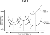
- FIG. 2 is a graph comparing relationships between flow coefficients and pressure loss coefficients in the scroll passage and the return channel.
- three kinds of impellers A to C having different flow coefficients ⁇ are used. These impellers A to C are provided in conventional centrifugal compressors each including the scroll passage and in the centrifugal compressors 1 of the present embodiment each including the return channel 13. Pressure loss coefficients ⁇ when such centrifugal compressors are operated are measured.
- the flow coefficient ⁇ increases in the order of the impeller A, the impeller B, and the impeller C.
- the impeller C having a larger flow coefficient ⁇ has a larger pressure loss coefficient ⁇ (see alternate long and short dash lines in FIG. 2 ).
- the fluid blown out from the impeller has a radial velocity component and a circumferential velocity component.
- the radial velocity component increases with an increase in flow rate.
- the scroll passage is a passage formed in a spiral shape in the circumferential direction.
- the fluid of the radial velocity component hinders the flow in the circumferential direction. Therefore, if the impeller having a large flow rate (flow coefficient ⁇ ) is employed, pressure loss when flowing through the scroll passage increases, thus resulting in reduced efficiency of the centrifugal compressor as shown in FIG. 2 .
- the fluid of the radial velocity component smoothly flows in the return channel 13 as mentioned above.
- the pressure loss coefficient ⁇ is substantially the same regardless of the magnitude of the flow coefficient ⁇ .
- the return passage 15 on the outlet side of the return channel 13 includes the return vane 15C, and the return vane 15C regulates the flow of the circumferential velocity component. Consequently, the fluid mainly having the radial velocity component flows out from the return channel 13. With the return channel 13, no hindering of the flow due to a spiral flow in a meridional cross section as in the scroll passage occurs, or no spiral velocity component is wasted at the outlet of the scroll passage. Thus, pressure loss when flowing through the return channel 13 can be reduced, thus improving the efficiency of the centrifugal compressor 1.
- the centrifugal compressor 1 in the above-described embodiment is configured to include the separately-provided driving mechanism for driving the rotary shaft 5
- the centrifugal compressor 1 may have a sealed structure in which an electric motor as a driving mechanism and a compressor are integrally included in a casing. According to this structure, the electric motor and the compressor are integrally provided in the casing, and the casing is sealed, for example. This eliminates a need to provide a sealing member (see the shaft seal 18 in FIG. 1 ) between the electric motor and the impeller 6, thus simplifying the configuration of the centrifugal compressor.
- the impeller 6 in the above-described embodiment has the cantilever supporting structure in which the impeller 6 is provided on the shaft end 5A of the rotary shaft 5, the present invention is not limited thereto.
- a bearing for pivotally supporting the rotary shaft 5 may be provided on the shaft end 5A between the impeller 6 and the discharge space 16A provided in the casing 2.
- the employment of a magnetic bearing, for example, as the bearing eliminates a need to provide, for example, a lubricating oil path for feeding a lubricating oil to the bearing.
- shaft vibration can be reduced while maintaining the simplified device configuration.
- a general bearing to which a lubricating oil is fed can be used if a space for providing the lubricating oil path can be allocated.
- the present invention is not limited thereto.
- a plurality (two or three, for example) of impellers 6 may be disposed on the rotary shaft 5, and an outlet of the upstream impeller 6 and an inlet of the downstream impeller 6 may be connected with the return channel 13.
- Such a configuration can achieve the improvement of efficiency at a large flow rate in the multistage centrifugal compressor 1 as well.
Landscapes
- Engineering & Computer Science (AREA)
- Mechanical Engineering (AREA)
- General Engineering & Computer Science (AREA)
- Structures Of Non-Positive Displacement Pumps (AREA)
Applications Claiming Priority (2)
| Application Number | Priority Date | Filing Date | Title |
|---|---|---|---|
| JP2014190466A JP6289323B2 (ja) | 2014-09-18 | 2014-09-18 | 遠心圧縮機 |
| PCT/JP2015/059342 WO2016042816A1 (ja) | 2014-09-18 | 2015-03-26 | 遠心圧縮機 |
Publications (1)
| Publication Number | Publication Date |
|---|---|
| EP3196479A1 true EP3196479A1 (en) | 2017-07-26 |
Family
ID=55532864
Family Applications (1)
| Application Number | Title | Priority Date | Filing Date |
|---|---|---|---|
| EP15842653.6A Withdrawn EP3196479A1 (en) | 2014-09-18 | 2015-03-26 | Centrifugal compressor |
Country Status (5)
| Country | Link |
|---|---|
| US (1) | US20180172023A1 (ja) |
| EP (1) | EP3196479A1 (ja) |
| JP (1) | JP6289323B2 (ja) |
| CN (1) | CN106662120A (ja) |
| WO (1) | WO2016042816A1 (ja) |
Cited By (1)
| Publication number | Priority date | Publication date | Assignee | Title |
|---|---|---|---|---|
| WO2020095023A1 (en) * | 2018-11-07 | 2020-05-14 | Dyson Technology Limited | Compressor with rotatable diffuser assembly |
Families Citing this family (1)
| Publication number | Priority date | Publication date | Assignee | Title |
|---|---|---|---|---|
| US10551598B2 (en) | 2016-01-06 | 2020-02-04 | Panavision International, L.P. | Anamorphic photography for digital imagers |
Family Cites Families (7)
| Publication number | Priority date | Publication date | Assignee | Title |
|---|---|---|---|---|
| US4693669A (en) * | 1985-03-29 | 1987-09-15 | Rogers Sr Leroy K | Supercharger for automobile engines |
| CN1081757C (zh) * | 1996-03-06 | 2002-03-27 | 株式会社日立制作所 | 离心压缩机以及用于离心压缩机的扩压器 |
| JP2002005089A (ja) * | 2000-06-20 | 2002-01-09 | Mitsubishi Heavy Ind Ltd | ターボ形圧縮機及びそれを備えた冷凍装置 |
| JP2003293995A (ja) * | 2002-04-02 | 2003-10-15 | Mitsubishi Heavy Ind Ltd | 遠心圧縮機及び遠心圧縮機の運転方法 |
| JP2004300929A (ja) * | 2003-03-28 | 2004-10-28 | Tokyo Electric Power Co Inc:The | 多段圧縮機、ヒートポンプ、並びに熱利用装置 |
| JP2011043130A (ja) * | 2009-08-24 | 2011-03-03 | Hitachi Appliances Inc | 遠心圧縮機及び冷凍装置 |
| JP5299354B2 (ja) * | 2010-06-01 | 2013-09-25 | 株式会社日立プラントテクノロジー | ターボ形流体機械 |
-
2014
- 2014-09-18 JP JP2014190466A patent/JP6289323B2/ja not_active Expired - Fee Related
-
2015
- 2015-03-26 CN CN201580044987.XA patent/CN106662120A/zh active Pending
- 2015-03-26 EP EP15842653.6A patent/EP3196479A1/en not_active Withdrawn
- 2015-03-26 US US15/504,075 patent/US20180172023A1/en not_active Abandoned
- 2015-03-26 WO PCT/JP2015/059342 patent/WO2016042816A1/ja active Application Filing
Cited By (1)
| Publication number | Priority date | Publication date | Assignee | Title |
|---|---|---|---|---|
| WO2020095023A1 (en) * | 2018-11-07 | 2020-05-14 | Dyson Technology Limited | Compressor with rotatable diffuser assembly |
Also Published As
| Publication number | Publication date |
|---|---|
| WO2016042816A1 (ja) | 2016-03-24 |
| US20180172023A1 (en) | 2018-06-21 |
| JP2016061239A (ja) | 2016-04-25 |
| CN106662120A (zh) | 2017-05-10 |
| JP6289323B2 (ja) | 2018-03-07 |
Similar Documents
| Publication | Publication Date | Title |
|---|---|---|
| JP4875644B2 (ja) | タービンおよびこれを備えるターボチャージャ | |
| US10400788B2 (en) | Intermediate intake-type diaphragm and centrifugal rotating machine | |
| EP2949946B1 (en) | Centrifugal rotation machine | |
| EP1990544A2 (en) | Multistage centrifugal compressor | |
| WO2015119140A1 (ja) | ダイアフラム、および遠心回転機械 | |
| US10871164B2 (en) | Centrifugal compressor | |
| JP6405590B2 (ja) | 圧縮機 | |
| EP3421815A1 (en) | Centrifugal compressor | |
| EP3196479A1 (en) | Centrifugal compressor | |
| EP3567260B1 (en) | Centrifugal rotary machine | |
| JP2010031777A (ja) | 多段遠心圧縮機 | |
| EP3048309B1 (en) | Rotating machine | |
| JP2020097940A (ja) | ターボ機械用の改良型スクロール、前記スクロールを備えたターボ機械、および動作方法 | |
| EP3885580A1 (en) | Impeller and centrifugal compressor | |
| JP5087160B2 (ja) | タービンおよびこれを備えるターボチャージャ | |
| JP2011231780A (ja) | タービンおよびこれを備えるターボチャージャ | |
| JP2019173617A (ja) | インレットガイドベーン及び圧縮機 | |
| US11873822B2 (en) | Centrifugal compressor | |
| KR102083925B1 (ko) | 압축 장치 | |
| EP3812593A1 (en) | Centrifugal compressor |
Legal Events
| Date | Code | Title | Description |
|---|---|---|---|
| PUAI | Public reference made under article 153(3) epc to a published international application that has entered the european phase |
Free format text: ORIGINAL CODE: 0009012 |
|
| 17P | Request for examination filed |
Effective date: 20170213 |
|
| AK | Designated contracting states |
Kind code of ref document: A1 Designated state(s): AL AT BE BG CH CY CZ DE DK EE ES FI FR GB GR HR HU IE IS IT LI LT LU LV MC MK MT NL NO PL PT RO RS SE SI SK SM TR |
|
| AX | Request for extension of the european patent |
Extension state: BA ME |
|
| DAV | Request for validation of the european patent (deleted) | ||
| DAX | Request for extension of the european patent (deleted) | ||
| STAA | Information on the status of an ep patent application or granted ep patent |
Free format text: STATUS: THE APPLICATION HAS BEEN WITHDRAWN |
|
| 18W | Application withdrawn |
Effective date: 20180411 |