EP3194767B1 - Windenergieanlage und verfahren zum steuern eines zuganges in einem abgeschlossenen bereich einer windenergieanlage - Google Patents
Windenergieanlage und verfahren zum steuern eines zuganges in einem abgeschlossenen bereich einer windenergieanlage Download PDFInfo
- Publication number
- EP3194767B1 EP3194767B1 EP15766443.4A EP15766443A EP3194767B1 EP 3194767 B1 EP3194767 B1 EP 3194767B1 EP 15766443 A EP15766443 A EP 15766443A EP 3194767 B1 EP3194767 B1 EP 3194767B1
- Authority
- EP
- European Patent Office
- Prior art keywords
- key
- unit
- fan
- wind turbine
- locking
- Prior art date
- Legal status (The legal status is an assumption and is not a legal conclusion. Google has not performed a legal analysis and makes no representation as to the accuracy of the status listed.)
- Active
Links
Images









Classifications
-
- F—MECHANICAL ENGINEERING; LIGHTING; HEATING; WEAPONS; BLASTING
- F16—ENGINEERING ELEMENTS AND UNITS; GENERAL MEASURES FOR PRODUCING AND MAINTAINING EFFECTIVE FUNCTIONING OF MACHINES OR INSTALLATIONS; THERMAL INSULATION IN GENERAL
- F16P—SAFETY DEVICES IN GENERAL; SAFETY DEVICES FOR PRESSES
- F16P3/00—Safety devices acting in conjunction with the control or operation of a machine; Control arrangements requiring the simultaneous use of two or more parts of the body
- F16P3/08—Safety devices acting in conjunction with the control or operation of a machine; Control arrangements requiring the simultaneous use of two or more parts of the body in connection with the locking of doors, covers, guards, or like members giving access to moving machine parts
-
- F—MECHANICAL ENGINEERING; LIGHTING; HEATING; WEAPONS; BLASTING
- F03—MACHINES OR ENGINES FOR LIQUIDS; WIND, SPRING, OR WEIGHT MOTORS; PRODUCING MECHANICAL POWER OR A REACTIVE PROPULSIVE THRUST, NOT OTHERWISE PROVIDED FOR
- F03D—WIND MOTORS
- F03D80/00—Details, components or accessories not provided for in groups F03D1/00 - F03D17/00
-
- F—MECHANICAL ENGINEERING; LIGHTING; HEATING; WEAPONS; BLASTING
- F03—MACHINES OR ENGINES FOR LIQUIDS; WIND, SPRING, OR WEIGHT MOTORS; PRODUCING MECHANICAL POWER OR A REACTIVE PROPULSIVE THRUST, NOT OTHERWISE PROVIDED FOR
- F03D—WIND MOTORS
- F03D80/00—Details, components or accessories not provided for in groups F03D1/00 - F03D17/00
- F03D80/50—Maintenance or repair
-
- F—MECHANICAL ENGINEERING; LIGHTING; HEATING; WEAPONS; BLASTING
- F03—MACHINES OR ENGINES FOR LIQUIDS; WIND, SPRING, OR WEIGHT MOTORS; PRODUCING MECHANICAL POWER OR A REACTIVE PROPULSIVE THRUST, NOT OTHERWISE PROVIDED FOR
- F03D—WIND MOTORS
- F03D80/00—Details, components or accessories not provided for in groups F03D1/00 - F03D17/00
- F03D80/80—Arrangement of components within nacelles or towers
-
- H—ELECTRICITY
- H01—ELECTRIC ELEMENTS
- H01H—ELECTRIC SWITCHES; RELAYS; SELECTORS; EMERGENCY PROTECTIVE DEVICES
- H01H27/00—Switches operated by a removable member, e.g. key, plug or plate; Switches operated by setting members according to a single predetermined combination out of several possible settings
- H01H27/06—Key inserted and then turned to effect operation of the switch
-
- F—MECHANICAL ENGINEERING; LIGHTING; HEATING; WEAPONS; BLASTING
- F05—INDEXING SCHEMES RELATING TO ENGINES OR PUMPS IN VARIOUS SUBCLASSES OF CLASSES F01-F04
- F05B—INDEXING SCHEME RELATING TO WIND, SPRING, WEIGHT, INERTIA OR LIKE MOTORS, TO MACHINES OR ENGINES FOR LIQUIDS COVERED BY SUBCLASSES F03B, F03D AND F03G
- F05B2260/00—Function
- F05B2260/30—Retaining components in desired mutual position
-
- F—MECHANICAL ENGINEERING; LIGHTING; HEATING; WEAPONS; BLASTING
- F05—INDEXING SCHEMES RELATING TO ENGINES OR PUMPS IN VARIOUS SUBCLASSES OF CLASSES F01-F04
- F05B—INDEXING SCHEME RELATING TO WIND, SPRING, WEIGHT, INERTIA OR LIKE MOTORS, TO MACHINES OR ENGINES FOR LIQUIDS COVERED BY SUBCLASSES F03B, F03D AND F03G
- F05B2260/00—Function
- F05B2260/30—Retaining components in desired mutual position
- F05B2260/31—Locking rotor in position
-
- F—MECHANICAL ENGINEERING; LIGHTING; HEATING; WEAPONS; BLASTING
- F05—INDEXING SCHEMES RELATING TO ENGINES OR PUMPS IN VARIOUS SUBCLASSES OF CLASSES F01-F04
- F05B—INDEXING SCHEME RELATING TO WIND, SPRING, WEIGHT, INERTIA OR LIKE MOTORS, TO MACHINES OR ENGINES FOR LIQUIDS COVERED BY SUBCLASSES F03B, F03D AND F03G
- F05B2260/00—Function
- F05B2260/60—Fluid transfer
- F05B2260/64—Aeration, ventilation, dehumidification or moisture removal of closed spaces
-
- F—MECHANICAL ENGINEERING; LIGHTING; HEATING; WEAPONS; BLASTING
- F05—INDEXING SCHEMES RELATING TO ENGINES OR PUMPS IN VARIOUS SUBCLASSES OF CLASSES F01-F04
- F05B—INDEXING SCHEME RELATING TO WIND, SPRING, WEIGHT, INERTIA OR LIKE MOTORS, TO MACHINES OR ENGINES FOR LIQUIDS COVERED BY SUBCLASSES F03B, F03D AND F03G
- F05B2270/00—Control
- F05B2270/60—Control system actuates through
- F05B2270/604—Control system actuates through hydraulic actuators
-
- Y—GENERAL TAGGING OF NEW TECHNOLOGICAL DEVELOPMENTS; GENERAL TAGGING OF CROSS-SECTIONAL TECHNOLOGIES SPANNING OVER SEVERAL SECTIONS OF THE IPC; TECHNICAL SUBJECTS COVERED BY FORMER USPC CROSS-REFERENCE ART COLLECTIONS [XRACs] AND DIGESTS
- Y02—TECHNOLOGIES OR APPLICATIONS FOR MITIGATION OR ADAPTATION AGAINST CLIMATE CHANGE
- Y02E—REDUCTION OF GREENHOUSE GAS [GHG] EMISSIONS, RELATED TO ENERGY GENERATION, TRANSMISSION OR DISTRIBUTION
- Y02E10/00—Energy generation through renewable energy sources
- Y02E10/70—Wind energy
- Y02E10/72—Wind turbines with rotation axis in wind direction
Definitions
- the present invention relates to a wind turbine and a method for controlling access in a closed area of a wind turbine.
- the rotor hub of a wind energy plant is typically connected to the generator rotor or to a transmission, so that by rotation of the rotor and the generator rotor is set in rotation and thus electrical energy is generated.
- the rotor hub of a wind energy plant is typically connected to the generator rotor or to a transmission, so that by rotation of the rotor and the generator rotor is set in rotation and thus electrical energy is generated.
- at the transition between the fixed area of the nacelle and the area of the rotating rotor can lead to serious accidents, if the rotor is not locked.
- DE 10 2010 043 436 A1 describes a device for controlling the locking of an opening of a door, which is provided between a stationary part and a rotating part of the wind turbine.
- the device has means for fixing the rotating part.
- the door between the rotating and stationary part of the wind turbine has a lock, wherein a release of the door is made possible when the means for fixing the rotating part have fixed the rotating part.
- a wind turbine with a nacelle with a fixed area and a rotor, at least one locking unit for locking the rotor and a Access control system provided.
- the access control system controls a locking of at least one access door to at least one closed area in the wind turbine in response to a locking of the rotor by means of the at least one locking unit.
- the enclosed area constitutes a converter cabinet with a fan in the nacelle.
- the access control system has a key transfer system and a hydraulic control unit for controlling the locking unit.
- the key transfer system includes a hydraulic key unit for preventing unintentional activation of the hydraulic unit and an access door key unit for locking or unlocking the access door.
- the key transfer system has at least a first and a second key, wherein by means of the first key, the hydraulic control unit is locked or unlocked and wherein by means of the second key, the access door key unit is locked or unlocked.
- the key transfer system further includes a fan key transfer unit for activating or deactivating the fan. Further, the first key of the hydraulic key unit is used for locking or unlocking the fan key transfer unit, and a fan key is used as the second key for locking or unlocking the access door key unit.
- the fan key transfer unit has first and second key units. In the first key unit, a first fan key is inserted
- the second key unit serves to receive the first key.
- a control unit is provided for controlling the at least one locking unit.
- the locking unit and / or the at least one access door is hydraulically actuated.
- the access doors are unlocked only when the rotor or parts thereof are locked.
- the fan is a fan of a gondola converter cabinet.
- the invention relates to the idea to provide a wind turbine with an access control system, wherein access to a converter cabinet with a fan in the nacelle of the wind turbine is only released when the rotor or rotatable parts of the rotor are locked.
- Fig. 1 shows a schematic representation of a wind turbine according to the invention.
- the wind energy plant 100 has a tower 102 and a pod 104.
- a rotor 106 with a rotor hub, three rotor blades 108 and a spinner 110 is arranged on the nacelle 104.
- the rotor 106 is set in rotation by the wind in rotation and thereby drives an electric generator 200 in the nacelle 104 at.
- Fig. 2 shows a schematic sectional view of a generator of a wind turbine according to a first embodiment.
- the wind turbine according to the first embodiment is based on a wind turbine according to Fig. 1 .
- a generator 200 is provided within the nacelle or within the rotor 106 or at the transition between the fixed part of the nacelle and the rotor 106.
- the generator 200 includes a generator stator 210 and a generator rotor 220.
- At least one locking unit 300 is provided on the generator rotor 220, which is configured to lock the generator rotor 220, so that the generator rotor 220 can not continue to rotate.
- At least one manhole 230 or an opening 230 may be provided in the area of the generator rotor 220. Through this manhole or the opening 230, service personnel can get into the front area of the wind turbine, namely the spinner 110.
- This spinner 110 is part of the rotor 106 and thus rotates as the rotor blades 108 rotate.
- a (hydraulic) control unit 310 is provided for controlling the locking units 300.
- This control unit 310 may be located both in the rotor 106 of the wind turbine and in the fixed part of the nacelle 104.
- the locking units 300 can be hydraulically operated, for example, so that, for example, bolts in corresponding openings in the rotor z. B. the generator when operating the hydraulic system can be moved.
- the control unit 310 may, for example, be configured as a hydraulic control unit 320 and actuate or activate the locking units 300 via the hydraulic lines 320.
- Fig. 3 shows a schematic representation of an access control system according to a second embodiment of the invention.
- a plurality of areas 410, 420, 430 may be provided, in which an access control, for example, to increase safety at work is desired. Access to these areas 410, 420, 430 is only to be released if this appears to be unobjectionable for reasons of occupational safety.
- the rotor 106 of the wind turbine or rotatable parts should be locked or fixed in the region of the nacelle 104.
- a main switch for fans or fans 410a in a nacelle converter cabinet 410 must be disabled before allowing access to the nacelle converter cabinet 410.
- the second area 420 may represent, for example, the area of the spinner 110 that may be secured by an access door 421.
- the third area 430 may optionally represent an area within the generator. This area 430 may also be secured by an access door 431.
- an access control system 500 is provided, which can be coupled both to the locking units 300 and to the access doors 411, 421, 431.
- the access control system 500 for example, the access to the doors 421, 431 and 411 release only when the rotor is locked by means of the locking units 300. It is checked whether a main switch for fans or fans in the nacelle converter cabinet 410 is deactivated.
- Fig. 4A - 4C each show a hydraulic diagram of the wind turbine according to a third embodiment.
- the hydraulic scheme z. B three locking units 300 (on the generator rotor) each with, for example, two locking pins 301 available.
- a hydraulic control unit 310 having a hydraulic pump 311 and a hydraulic travel valve 312 is shown.
- at least one door closing unit 421 is shown with a hydraulically closable door 421a, a hydraulically actuatable opener 421b and a hydraulic short cylinder 421c.
- the directional control valve 312 When the directional control valve 312 is in a first mode, then the locking of the locking units 300 is activated so that the bolts 301 are extended and locked to one of the openers 302, respectively. This situation is in Fig. 4B shown. Subsequently, the directional control valve 312 may be set in a second mode of operation (see FIG. Fig. 4C ), that with activated locking units 300, the door 411, 421, 431 can be unlocked so that service personnel can enter the areas 410, 420, 430.
- Fig. 5 shows a schematic view of a hydraulic control unit of an access control system according to a fourth embodiment.
- the hydraulic control unit 3100 is part of an access control system 500 for a wind turbine.
- the access control system 500 according to the fourth embodiment may be based on an access control system according to the first, second or third embodiment.
- the hydraulic control unit 3100 includes an electric hydraulic pump 3110, a manual pump 3120, a hydraulic switching valve 3130, hydraulic hose quick couplings 3140, and a hydraulic key unit 3150a. With the switching valve 3130, the flow of the hydraulic fluid can be activated or deactivated.
- the hydraulic key unit 3150a it is to be ensured that the turn-over valve 3130 is released only under certain conditions.
- the hydraulic key unit 3150a is part of the access control system.
- Figs. 6A-6D each show a schematic representation of an operation of an access control system according to the fourth embodiment.
- the locking unit 300 which has extendable bolts 301
- the generator rotor 220 is to be locked.
- the bolts 301 can be moved into corresponding recesses 221 in the generator rotor 220.
- a pulsor or other optical, electrical or magnetic sensor 300a is provided in the region of the locking unit 300 and monitors whether the bolts 301 are extended or not. This is in the Figs. 6A-6D each shown on the top right.
- the locking units 300 with the extendable bolts 301 are each shown schematically.
- the locking units 300 are coupled via hydraulic lines to a directional control valve 3130 and the hand pump 3120 and / or the electric pump 3110.
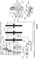
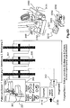
- a detail of the hydraulic control unit 3100 is shown at different times during the locking of the rotor. Furthermore, in the Figs. 6A-6D a ventilator key unit 3200 as a second part of the key transfer unit 500 is shown schematically below.
- Fig. 6A the situation is shown in which the two bowls 3151, 3152 of the first hydraulic key transfer unit 3150 have been rotated by 90 ° and the bolts 301 are not extended.
- the turning of the keys 3151, 3152 and thus removal of the keys 3151, 3152 can only take place when the lever 3131 of the changeover valve 3130 has been brought into the correct position.
- the locking of the rotor can be activated by the hand pump 3120 is actuated.
- Fig. 6B the time is shown at which the bolts 301 are not extended. At this time, for example, an access door is locked and / or the fan is switched on.
- the wind turbine according to the invention record their normal operation.
- the keys 3151 and 3152 are in a home position. The keys can not be removed.
- the switching valve 3130 is optionally freely pivotable.
- Fig. 6C the situation is shown in which the bolts 301 are partially extended. This is detected by the optical sensor 300a and the electric pump 3110 is released so that the bolts 301 can be further extended.
- Fig. 6D the situation is shown in which the bolts 301 are fully extended and thus located within the recesses 221. Thus, the locking operation is completed and the rotor 106 of the wind turbine can not turn.
- FIGs. 6A-6D A fan key unit 3200 is shown as a second part of the key transfer unit 500 at the bottom right.
- the fan key unit 3200 will be closer in Fig. 8 and Fig. 9A and 9B described.
- the fan switch 3210 is set to "on” and the fan key transfer unit 3200 is locked.
- Fig. 7A and 7B each show a detailed view of the hydraulic control unit of Fig. 5 .
- Fig. 7A is the time according to Fig. 6B shown.
- the two keys 3151, 3152 have each been actuated to release a bolt 3153.
- Fig. 7B For example, the situation where the first and second keys 3151, 3152 have been operated so that the bolt 3153 is extended is shown. In this case, the bolt 3153 moves into a recess 3132 of the changeover valve unit 3130 and thus locks the changeover valve unit 3130.
- Fig. 7A the recess 3132 is shown, which is arranged below the extendable bolt.
- the two keys 3151, 3152 are rotatable.
- the keys are aligned in the longitudinal direction of the extending bolt and are removable.
- Fig. 8 shows a schematic representation for illustrating a key transfer system according to the invention an access control system.
- the envelope valve unit 3130 can not be operated.
- the two keys 3151 and 3152 may be removed and one of the keys may be inserted into the fan key transfer unit 3200 to deactivate the fan.
- the fan key transfer unit 3200 has first and second key units 3220, 3230.
- the first key unit 3220 is inserted with a first fan key 3221.
- the second key unit 3232 serves to receive the first key 3151.
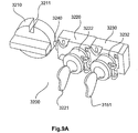
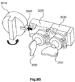
- Fig. 9A and 9B show schematic representations of a fan key unit for a fan according to the invention.
- Fig. 9A and 9B Two different states of the fan key unit 3200 are shown.
- Fig. 9A the first state is shown in which the fan is still activated and the first key 3151 is inserted into the second key unit 3230.
- Fig. 9B the situation is shown where the first key 3151 is placed in the second key unit 3230 and rotated 90 °.
- the fan must be turned off beforehand so that the bolt 3240 of the fan key unit 3200 can be inserted into the recess 3211.
- the control 3210 can be rotated by 90 °.
- a bolt 3240 can be inserted into the recess 3211 of the operating unit 3210 and can thus lock the operating unit 3210 of the fan.
- Fig. 9A When the fan is turned on, the fan key 3221 is locked and the key 3151 is inserted. In Fig. 9B the key 3151 is turned and thus locked. At the same time the fan key 3221 is unlocked and can be removed. At the same time, the bolt 3240 moves into the recess 3211 and locks the operating element of the fan. This turns off the fan.
- Fig. 10 shows a schematic representation of a section of a key transfer system according to the invention.
- the situation is shown in which the fan is turned off and the bolt 3240 is inserted into the recess 3211.
- the first key 3151 is in a locked state and the fan key 3221 can then be removed and placed in an access door key unit 3300 as a third part of the key transfer unit 500 to unlock the access door 3320. Only after the key 3221 has been inserted and operated in the access door key unit 3300 can the door 3320 be unlocked.
- Fig. 11 shows a further section of the hydraulic control system of Fig. 5 ,
- the state is shown in which the rotor 106 of the wind turbine to be unlocked. If the release has been granted for locking, then the keys 3151, 3152 can be rotated 90 degrees when the change-over valve has been set to the appropriate position so that the key unit bolt 3153 can be slid into the recess. Thus, the lock can be actuated only in the locking direction.
- valve position of the changeover valve is set to bolts and the key 3151 is inserted.
- the bolt 3153 z. B. when turning the key 3151 retract and thus release the lever 3131.
- Figs. 12A-12B each show a schematic view for illustrating the access control system according to the invention.
- Fig. 12A the situation is shown in which the generator rotor or the rotor 106 of the wind turbine is locked by means of the bolts 301 of the locking unit (see top left).
- the bolts 301 are extended and located in the recesses 221 of the generator rotor.
- the first and second keys 3151, 3152 are respectively in the key transfer unit and the envelope valve unit 3130 is locked (see right).
- the third key 3221 is in the fan key unit 3200 and the fan is on. Further, both the electric pump 3110 and the hand pump 3120 are activated.
- Fig. 12B the situation is shown in which the bolts 301 have moved back into the locking unit 300 and the rotor is thus no longer locked. In this case, the electric pump 3110 is deactivated.
- the 3221 key To release the rotor, the 3221 key must be removed from the 3300 Access Door Key Unit. However, this can only be done when the access door 3320 is closed. The key 3221 must then be inserted into the fan key unit 3200 and there into the first key unit 3220 and rotated by 90 °. The key 3151 must also be rotated 90 ° and then removed to be inserted into the hydraulic key unit. Only when both keys 3151, 3152 have been inserted and rotated by 90 °, then the bolt 3153 can be retracted again and the turn-over valve 3130 can be returned by means of the lever 3131 again.
- the fan key unit may be omitted.
- the first key 3151 may be used to activate the hydraulic control unit and a second key may be used as the key 3221 for the access door key unit 3330, i. H. the key 3131 can be used to unlock the access door.
- the key of the hydraulic key unit is stuck in the access door key unit as long as the access door is open.
- the key can first be removed and inserted into the hydraulic key unit to unlock the hydraulic unit. This ensures that the access door is closed when the valve position of the hydraulic unit is changed.
Landscapes
- Engineering & Computer Science (AREA)
- General Engineering & Computer Science (AREA)
- Mechanical Engineering (AREA)
- Life Sciences & Earth Sciences (AREA)
- Sustainable Development (AREA)
- Sustainable Energy (AREA)
- Chemical & Material Sciences (AREA)
- Combustion & Propulsion (AREA)
- Wind Motors (AREA)
Description
- Die vorliegende Erfindung betrifft eine Windenergieanlage und ein Verfahren zum Steuern eines Zugangs in einem abgeschlossenen Bereich einer Windenergieanlage.
- Die Rotornabe einer Windenergieanlage ist typischerweise mit dem Generator-Rotor bzw. mit einem Getriebe verbunden, so dass durch Drehung des Rotors auch der Generator-Rotor in Rotation versetzt wird und somit elektrische Energie erzeugt wird. Insbesondere beim Übergang zwischen dem feststehenden Bereich der Gondel und dem Bereich des sich drehenden Rotors kann es zu folgenschweren Unfällen kommen, wenn der Rotor nicht arretiert ist.
-
DE 10 2010 043 436 A1 beschreibt eine Vorrichtung zum Steuern der Verriegelung einer Öffnung einer Tür, welche zwischen einem stehenden Teil und einem drehenden Teil der Windenergieanlage vorgesehen ist. Die Vorrichtung weist Mittel zur Fixierung des drehenden Teils auf. Die Tür zwischen dem drehenden und stehenden Teil der Windenergieanlage weist eine Verriegelung auf, wobei eine Entriegelung der Tür ermöglicht wird, wenn die Mittel zur Fixierung des drehenden Teils den drehenden Teil fixiert haben. - In der prioritätsbegründenden deutschen Patentanmeldung hat das Deutsche Patent- und Markenamt die folgenden Dokumente recherchiert:
DE 10 2006 006 949 A1 ,DE 10 2010 043 436 A1 undEP 2 740 928 A1 . - Es ist somit eine Aufgabe der vorliegenden Erfindung, eine Windenergieanlage mit einem Zugangskontrollsystem vorzusehen, um einen Zugang von Personen zu gefährlichen Bereichen der Windenergieanlage zu vermeiden, solange der Rotor bzw. Teile des Rotors rotieren können.
- Diese Aufgabe wird durch eine Windenergieanlage nach Anspruch 1 gelöst.
- Somit wird eine Windenergieanlage mit einer Gondel mit einem feststehenden Bereich und einem Rotor, mindestens einer Arretiereinheit zum Arretieren des Rotors und einem Zugangskontrollsystem vorgesehen. Das Zugangskontrollsystem steuert eine Verriegelung mindestens einer Zugangstür zu mindestens einem abgeschlossenen Bereich in der Windenergieanlage in Abhängigkeit einer Arretierung des Rotors mittels der mindestens einen Arretiereinheit. Der abgeschlossene Bereich stellt einen Umrichterschrank mit einem Lüfter in der Gondel dar. Das Zugangskontrollsystem weist ein Schlüsseltransfersystem und eine Hydraulik-Steuereinheit zum Steuern der Arretiereinheit auf. Das Schlüsseltransfersystem weist eine Hydraulik-Schlüsseleinheit zum Verhindern einer unbeabsichtigten Aktivierung der Hydraulikeinheit und eine Zugangstür-Schlüsseleinheit zum Verriegeln oder Entriegeln der Zugangstür auf. Das Schlüsseltransfersystem weist mindestens einen ersten und zweiten Schlüssel auf, wobei mittels des ersten Schlüssels die Hydraulik-Steuereinheit verriegelt oder entriegelt wird und wobei mittels des zweiten Schlüssels die Zugangstür-Schlüsseleinheit verriegelt oder entriegelt wird. Das Schlüsseltransfersystem weist ferner eine Lüfter-Schlüsseltransfereinheit zum Aktivieren oder Deaktivieren des Lüfters auf. Ferner wird der erste Schlüssel der Hydraulik-Schlüsseleinheit zum Verriegeln oder Entriegeln der Lüfter-Schlüsseltransfereinheit verwendet und ein Lüfter-Schlüssel wird als zweiter Schlüssel zum Verriegeln oder Entriegeln der Zugangstür-Schlüsseleinheit verwendet. Die Lüfter-Schlüsseltransfereinheit weist eine erste und zweite Schlüsseleinheit auf. In die erste Schlüsseleinheit ist ein erster Lüfter-Schlüssel einführbar
- Die zweite Schlüsseleinheit dient zur Aufnahme des ersten Schlüssels.
- Gemäß einem weiteren Aspekt der vorliegenden Erfindung ist eine Steuereinheit zum Steuern der mindestens einen Arretiereinheit vorgesehen.
- Gemäß einer weiteren Ausgestaltung der Erfindung ist die Arretiereinheit und/oder die mindestens eine Zugangstür hydraulisch betätigbar.
- Gemäß der Erfindung werden die Zugangstüren nur dann entriegelt, wenn der Rotor bzw. Teile davon arretiert sind.
- Der Lüfter stellt einen Lüfter eines Gondelumrichterschranks dar.
- Die Erfindung betrifft den Gedanken, eine Windenergieanlage mit einem Zugangskontrollsystem vorzusehen, wobei ein Zugang zu einem Umrichterschrank mit einem Lüfter in der Gondel der Windenergieanlage nur dann freigegeben wird, wenn der Rotor bzw. drehbare Teile des Rotors arretiert sind.
- Weitere Ausgestaltungen der Erfindung sind Gegenstand der Unteransprüche.
- Vorteile und Ausführungsbeispiele der Erfindung werden nachstehend unter Bezugnahme auf die Zeichnung näher erläutert.
- Fig. 1
- zeigt eine schematische Darstellung einer Windenergieanlage gemäß der Erfindung,
- Fig. 2
- zeigt eine schematische Schnittansicht eines Generators einer Windenergieanlage gemäß einem ersten Ausführungsbeispiel,
- Fig. 3
- zeigt eine schematische Darstellung eines Zugangskontrollsystems gemäß einem zweiten Ausführungsbeispiel,
- Fig. 4A-4C
- zeigen jeweils ein Hydraulikschema des Zugangskontrollsystems gemäß einem dritten Ausführungsbeispiel,
- Fig. 5
- zeigt eine schematische Darstellung einer Hydrauliksteuereinheit eines Zugangskontrollsystems gemäß einem vierten Ausführungsbeispiel,
- Fig. 6A - 6D
- zeigen jeweils eine schematische Darstellung einer Funktionsweise eines Zugangskontrollsystems gemäß dem vierten Ausführungsbeispiel,
- Fig. 7A und 7B
- zeigen jeweils eine Detailansicht der Hydrauliksteuereinheit von
Fig. 5 , - Fig. 8
- zeigt eine schematische Darstellung zur Veranschaulichung eines erfindungsgemäßen Schlüsseltransfersystems eines Zugangskontrollsystems,
- Fig. 9A und 9B
- zeigen schematische Darstellungen eines Schlüsselsystems für einen Lüfter gemäß der Erfindung,
- Fig. 10
- zeigt eine schematische Darstellung eines Ausschnitts eines Schlüsseltransfersystems gemäß der Erfindung,
- Fig. 11
- zeigt einen weiteren Ausschnitt des Hydrauliksteuersystems von
Fig. 5 , und - Fig. 12A - 12B
- zeigen jeweils eine schematische Ansicht zur Veranschaulichung des erfindungsgemäßen Schlüsseltransfersystems eines Zugangskontrollsystems .
-
Fig. 1 zeigt eine schematische Darstellung einer Windenergieanlage gemäß der Erfindung. Die Windenergieanlage 100 weist einen Turm 102 und eine Gondel 104 auf. An der Gondel 104 ist ein Rotor 106 mit einer Rotornabe, drei Rotorblättern 108 und einem Spinner 110 angeordnet. Der Rotor 106 wird im Betrieb durch den Wind in eine Drehbewegung versetzt und treibt dadurch einen elektrischen Generator 200 in der Gondel 104 an. -
Fig. 2 zeigt eine schematische Schnittansicht eines Generators einer Windenergieanlage gemäß einem ersten Ausführungsbeispiel. Die Windenergieanlage gemäß dem ersten Ausführungsbeispiel basiert auf einer Windenergieanlage gemäßFig. 1 . Innerhalb der Gondel bzw. innerhalb des Rotors 106 bzw. am Übergang zwischen dem feststehenden Teil der Gondel und dem Rotor 106 ist ein Generator 200 vorgesehen. Der Generator 200 weist einen Generator-Stator 210 und einen Generator-Rotor 220 auf. An dem Generator-Rotor 220 ist mindestens eine Arretiereinheit 300 vorgesehen, welche dazu ausgestaltet ist, den Generator-Rotor 220 zu arretieren, so dass sich der Generator-Rotor 220 nicht weiterdrehen kann. Im Bereich des Generator-Rotors 220 kann mindestens ein Mannloch 230 oder eine Öffnung 230 vorgesehen sein. Durch dieses Mannloch bzw. die Öffnung 230 kann Servicepersonal in den vorderen Bereich der Windenergieanlage, nämlich den Spinner 110, gelangen. Dieser Spinner 110 ist Teil des Rotors 106 und dreht sich somit, wenn die Rotorblätter 108 sich drehen. - Zur Steuerung der Arretiereinheiten 300 ist eine (Hydraulik-)Steuereinheit 310 vorgesehen. Diese Steuereinheit 310 kann sich sowohl in dem Rotor 106 der Windenergieanlage als auch im feststehenden Teil der Gondel 104 befinden.
- Die Arretiereinheiten 300 können beispielsweise hydraulisch betrieben werden, so dass beispielsweise Bolzen in entsprechende Öffnungen in dem Rotor z. B. des Generators bei Betätigung der Hydraulik verfahren werden können. Die Steuereinheit 310 kann beispielsweise als eine Hydrauliksteuereinheit 320 ausgestaltet sein und über die Hydraulikleitungen 320 die Arretiereinheiten 300 betätigen bzw. aktivieren.
-
Fig. 3 zeigt eine schematische Darstellung eines Zugangskontrollsystems gemäß einem zweiten Ausführungsbeispiel der Erfindung. Im Bereich der Gondel 104 der Windenergieanlage 100 können mehrere Bereiche 410, 420, 430 vorgesehen sein, bei denen eine Zugangskontrolle beispielsweise zur Erhöhung der Arbeitssicherheit gewünscht ist. Der Zugang zu diesen Bereichen 410, 420, 430 soll nur dann freigegebenen werden, wenn dies aus arbeitssicherheitsrechtlichen Überlegungen unbedenklich erscheint. Hierzu sollte beispielsweise der Rotor 106 der Windenergieanlage bzw. drehbare Teile im Bereich der Gondel 104 arretiert bzw. festgesetzt sein. - Ein Hauptschalter für Ventilatoren oder Lüfter 410a in einem Gondelumrichterschrank 410 muss deaktiviert sein, bevor ein Zugang zu dem Gondelumrichterschrank 410 ermöglicht wird. Der zweite Bereich 420 kann beispielsweise der Bereich des Spinners 110 darstellen, der durch eine Zugangstür 421 gesichert werden kann. Der dritte Bereich 430 kann beispielsweise optional einen Bereich innerhalb des Generators darstellen. Dieser Bereich 430 kann ebenfalls durch eine Zugangstür 431 gesichert sein. Gemäß der Erfindung ist ein Zugangskontrollsystem 500 vorgesehen, welches sowohl mit den Arretiereinheiten 300 als auch mit den Zugangstüren 411, 421, 431 gekoppelt sein kann. Hierbei kann das Zugangskontrollsystem 500 den Zugang beispielswiese zu den Türen 421, 431 und 411 nur dann freigeben, wenn der Rotor mittels der Arretiereinheiten 300 arretiert ist. Es wird überprüft, ob ein Hauptschalter für Ventilatoren oder Lüfter in dem Gondelumrichterschrank 410 deaktiviert ist.
-
Fig. 4A - 4C zeigen jeweils ein Hydraulikschema der Windenergieanlage gemäß einem dritten Ausführungsbeispiel. In dem Hydraulikschema sind z. B. drei Arretiereinheiten 300 (an dem Generator-Rotor) jeweils mit beispielsweise zwei Arretierbolzen 301 vorhanden. Ferner ist eine Hydrauliksteuereinheit 310 mit einer Hydraulikpumpe 311 und einem Hydraulikwegeventil 312 gezeigt. Des Weiteren ist mindestens eine Türschließeinheit 421 mit einer hydraulisch verschließbaren Tür 421a, einem hydraulisch betätigbaren Öffner 421b und einem Hydrauliktürzylinder 421c gezeigt. - Wenn sich das Wegeventil 312 in einer ersten Betriebsart befindet, dann wird die Arretierung der Arretiereinheiten 300 aktiviert, so dass die Bolzen 301 ausgefahren werden und jeweils mit einem der Öffner 302 verriegelt werden. Diese Situation ist in
Fig. 4B gezeigt. Anschließend kann das Wegeventil 312 in einer zweiten Betriebsart derart eingestellt sein (s.Fig. 4C ), dass bei aktivierten Arretiereinheiten 300 die Tür 411, 421, 431 entriegelt werden kann, so dass Servicepersonal in die Bereiche 410, 420, 430 eintreten kann. -
Fig. 5 zeigt eine schematische Ansicht einer Hydrauliksteuereinheit eines Zugangskontrollsystems gemäß einem vierten Ausführungsbeispiel. Die Hydrauliksteuereinheit 3100 ist Teil eines Zugangskontrollsystems 500 für eine Windenergieanlage. Hierbei kann das Zugangskontrollsystem 500 gemäß dem vierten Ausführungsbeispiel auf einem Zugangskontrollsystem gemäß dem ersten, zweiten oder dritten Ausführungsbeispiel beruhen. Durch das Zugangskontrollsystem 500 soll insbesondere vermieden werden, dass ein Zugang zu den sich drehenden Teilen der Windenergieanlage, z. B. der Spinner der Windenergieanlage, möglich ist. Die Hydrauliksteuereinheit 3100 weist eine elektrische hydraulische Pumpe 3110, eine Handpumpe 3120, ein Hydraulikumschaltventil 3130, Schnellkupplungen 3140 für Hydraulikschläuche und eine Hydraulikschlüsseleinheit 3150a auf. Mit dem Umschaltventil 3130 kann der Durchfluss der Hydraulikflüssigkeit aktiviert oder deaktiviert werden. Mittels der Hydraulikschlüsseleinheit 3150a soll sichergestellt werden, dass das Umschlagventil 3130 nur unter bestimmten Bedingungen frei gegeben wird. Die Hydraulikschlüsseleinheit 3150a ist Teil des Zugangskontrollsystems. -
Fig. 6A-6D zeigen jeweils eine schematische Darstellung einer Funktionsweise eines Zugangskontrollsystems gemäß dem vierten Ausführungsbeispiel. Mittels der Arretiereinheit 300, welche über ausfahrbare Bolzen 301 verfügt, soll der Generator-Rotor 220 arretiert werden. Hierzu können die Bolzen 301 in entsprechende Ausnehmungen 221 in dem Generator-Rotor 220 verfahren werden. Ein Pulsor oder ein anderer optischer, elektrischer oder magnetischer Sensor 300a ist im Bereich der Arretiereinheit 300 vorgesehen und überwacht, ob die Bolzen 301 ausgefahren sind oder nicht. Dies ist in denFig. 6A-6D jeweils oben rechts gezeigt. - In der Mitte der
Fig. 6A - 6D sind die Arretiereinheiten 300 mit den ausfahrbaren Bolzen 301 jeweils schematisch gezeigt. Die Arretiereinheiten 300 sind über Hydraulikleitungen mit einem Wegeventil 3130 und der Handpumpe 3120 und/oder der elektrischen Pumpe 3110 gekoppelt. - In den
Fig. 6A - 6D ist auf der rechten Seite jeweils ein Ausschnitt der Hydrauliksteuereinheit 3100 zu verschiedenen Zeitpunkten während der Arretierung des Rotors gezeigt. Ferner ist in denFig. 6A - 6D rechts unten jeweils schematisch eine Lüfter-Schlüsseleinheit 3200 als zweiter Teil der Schlüsseltransfereinheit 500 gezeigt. - In
Fig. 6A ist die Situation gezeigt, bei der die beiden Schüssel 3151, 3152 der ersten Hydraulik-Schlüsseltransfereinheit 3150 um 90° gedreht worden sind und die Bolzen 301 sind nicht ausgefahren. Das Drehen der Schlüssel 3151, 3152 und damit ein Entfernen der Schlüssel 3151, 3152 kann nur erfolgen, wenn der Hebel 3131 des Umschaltventils 3130 in die richtige Position gebracht worden ist. Zu diesem Zeitpunkt kann die Arretierung des Rotors aktiviert werden, indem die Handpumpe 3120 betätigt wird. - In
Fig. 6B ist der Zeitpunkt gezeigt, bei dem die Bolzen 301 nicht ausgefahren sind. Zu diesem Zeitpunkt ist beispielsweise eine Zugangstür verriegelt und/oder der Lüfter ist eingeschaltet. Somit kann die Windenergieanlage gemäß der Erfindung ihren Normalbetrieb aufnehmen. Während des Normalbetriebs der Windenergieanlage (d.h. der Rotor ist nicht arretiert) befinden sich die Schlüssel 3151 und 3152 in einer Grundposition. Die Schlüssel können nicht entnommen werden. Das Umschaltventil 3130 ist optional frei schwenkbar. - In
Fig. 6C ist die Situation gezeigt, bei der die Bolzen 301 teilweise ausgefahren sind. Dies wird durch den optischen Sensor 300a erfasst und die elektrische Pumpe 3110 wird frei gegeben, so dass die Bolzen 301 weiter ausgefahren werden können. - In
Fig. 6D ist die Situation gezeigt, bei der die Bolzen 301 komplett ausgefahren sind und sich somit innerhalb der Ausnehmungen 221 befinden. Damit ist der Arretierungsvorgang abgeschlossen und der Rotor 106 der Windenergieanlage kann sich nicht mehr drehen. - In den
Fig. 6A - 6D ist rechts unten jeweils eine Lüfter-Schlüsseleinheit 3200 als zweiter Teil der Schlüsseltransfereinheit 500 gezeigt. Die Lüfter-Schlüsseleinheit 3200 wird näher inFig. 8 undFig. 9A und9B beschrieben. In den in denFig. 6A - 6D gezeigten Zuständen ist der Lüfterschalter 3210 auf "ein" eingestellt und die Lüfter-Schlüsseltransfereinheit 3200 ist arretiert. - In dem in
Fig. 6A gezeigten Zustand ist der Hebel 3131 des Umschaltventils 3130 in einer ersten Position, in der die Hydraulik-Schlüsseleinheit und die beiden Schlüssel 3151, 3152 arretiert sind und somit nicht abgezogen werden können. InFig. 6B ist der Hebel 3131 in einer zweiten Position. Entsprechendes gilt für die Situation in denFig. 6C und6D . - In den in den
Fig. 6A- 6D gezeigten Situationen sind die beiden Schlüssel 3151, 3152 in der Hydraulik-Schlüsseleinheit 3150 arretiert und können nicht abgezogen werden. InFig. 6B - 6D ist der Hebel 3131 des Umschaltventils 3130 in einer Einbolzposition. Dadurch ist eine Ausnehmung unterhalb des Bolzens angeordnet. -
Fig. 7A und7B zeigen jeweils eine Detailansicht der Hydrauliksteuereinheit vonFig 5 . - In
Fig. 7A ist der Zeitpunkt gemäßFig. 6B gezeigt. Die beiden Schlüssel 3151, 3152 sind jeweils betätigt worden, um einen Bolzen 3153 freizugeben. - In
Fig. 7B ist die Situation gezeigt, bei der der erste und zweite Schlüssel 3151, 3152 betätigt worden sind, so dass der Bolzen 3153 ausgefahren wird. Dabei fährt der Bolzen 3153 in eine Ausnehmung 3132 der Umschaltventileinheit 3130 ein und arretiert somit die Umschaltventileinheit 3130. - In
Fig. 7A ist die Ausnehmung 3132 gezeigt, welche unterhalb des ausfahrbaren Bolzens angeordnet ist. In dem Ausführungsbeispiel vonFig. 7A und7B sind die beiden Schlüssel 3151, 3152 drehbar. InFig. 7B sind die Schlüssel in Längsrichtung des ausfahrenden Bolzens ausgerichtet und sind entnehmbar. -
Fig. 8 zeigt eine schematische Darstellung zur Veranschaulichung eines erfindungsgemäßen Schlüsseltransfersystems eines Zugangskontrollsystems. Nachdem der Bolzen 3153 ausgefahren worden ist und sich somit in der Ausnehmung 3132 befindet, kann die Umschlagventileinheit 3130 nicht betätigt werden. Anschließend können die beiden Schlüssel 3151 und 3152 entfernt werden und einer der Schlüssel kann in die Lüfter-Schlüsseltransfereinheit 3200 eingeführt werden, um den Lüfter zu deaktivieren. Die Lüfter-Schlüsseltransfereinheit 3200 weist eine erste und zweite Schlüsseleinheit 3220, 3230 auf. In die erste Schlüsseleinheit 3220 wird ein erster Lüfter-Schlüssel 3221 eingeführt. Die zweite Schlüsseleinheit 3232 dient der Aufnahme des ersten Schlüssels 3151. -
Fig. 9A und9B zeigen schematische Darstellungen einer Lüfter-Schlüsseleinheit für einen Lüfter gemäß der Erfindung. InFig. 9A und9B sind zwei verschiedene Zustände der Lüfter-Schlüsseleinheit 3200 gezeigt. InFig. 9A ist der erste Zustand gezeigt, bei dem der Lüfter noch aktiviert ist und der erste Schlüssel 3151 in die zweite Schlüsseleinheit 3230 eingeführt wird. InFig. 9B ist die Situation gezeigt, bei der der erste Schlüssel 3151 in der zweiten Schlüsseleinheit 3230 platziert ist und um 90° gedreht ist. Der Lüfter muss vorher ausgeschaltet werden, damit der Bolzen 3240 der Lüfter-Schlüsseleinheit 3200 in die Ausnehmung 3211 eingeschoben werden kann. Dazu kann das Bedienelement 3210 um 90° gedreht werden. In diesem Fall kann ein Bolzen 3240 in die Ausnehmung 3211 der Bedieneinheit 3210 eingeführt werden und kann damit die Bedieneinheit 3210 des Lüfters verriegeln. - In
Fig. 9A ist der Lüfter eingeschaltet, der Lüfter-Schlüssel 3221 ist verriegelt und der Schlüssel 3151 ist eingesteckt. InFig. 9B ist der Schlüssel 3151 gedreht und somit verriegelt. Gleichzeitig ist der Lüfter-Schlüssel 3221 entriegelt und kann entfernt werden. Gleichzeitig fährt der Bolzen 3240 in die Ausnehmung 3211 ein und verriegelt das Bedienelement des Lüfters. Damit ist der Lüfter ausgeschaltet. -
Fig. 10 zeigt eine schematische Darstellung eines Ausschnitts eines Schlüsseltransfersystems gemäß der Erfindung. InFig. 10 ist die Situation gezeigt, bei der der Lüfter ausgeschaltet ist und der Bolzen 3240 in die Ausnehmung 3211 eingeführt ist. Der erste Schlüssel 3151 befindet sich in einem verriegelten Zustand und der Lüfter-Schlüssel 3221 kann dann entfernt werden und kann in eine Zugangstür-Schlüsseleinheit 3300 als dritter Teil der Schlüsseltransfereinheit 500 platziert werden, um die Zugangstür 3320 zu entriegeln. Erst nachdem der Schlüssel 3221 in die Zugangstür-Schlüsseleinheit 3300 eingeführt und betätigt worden ist, kann die Tür 3320 entriegelt werden. -
Fig. 11 zeigt einen weiteren Ausschnitt des Hydrauliksteuersystems vonFig. 5 . InFig. 11 ist der Zustand gezeigt, bei dem der Rotor 106 der Windenergieanlage entriegelt werden soll. Wenn die Freigabe zum Arretieren erteilt wurde, dann können die Schlüssel 3151, 3152 um 90 Grad gedreht werden, wenn das Umschaltventil in die entsprechende Stellung gebracht wurde, so dass der Bolzen 3153 der Schlüsseleinheit in die Ausnehmung geschoben werden kann. Damit kann die Arretierung nur in die Arretierrichtung betätigt werden. - In
Fig. 11 ist die Ventilstellung des Umschaltventils auf Einbolzen eingestellt und der Schlüssel 3151 ist eingesteckt. Hierbei kann der Bolzen 3153 z. B. beim Drehen des Schlüssels 3151 einfahren und somit den Hebel 3131 freigeben. -
Fig. 12A-12B zeigen jeweils eine schematische Ansicht zur Veranschaulichung des erfindungsgemäßen Zugangskontrollsystems. InFig. 12A ist die Situation gezeigt, bei der der Generator-Rotor oder der Rotor 106 der Windenergieanlage mittels der Bolzen 301 der Arretiereinheit arretiert ist (s. oben links). Mit anderen Worten, die Bolzen 301 sind ausgefahren und befinden sich in den Ausnehmungen 221 des Generator-Rotors. Der erste und zweite Schlüssel 3151, 3152 befinden sich jeweils in der Schlüsseltransfereinheit und die Umschlagventileinheit 3130 ist arretiert (s. rechts). Der dritte Schlüssel 3221 befindet sich in der Lüfter-Schlüsseleinheit 3200 und der Lüfter ist eingeschaltet. Ferner ist sowohl die elektrische Pumpe 3110 als auch die Handpumpe 3120 aktiviert. - In
Fig. 12B ist die Situation gezeigt, bei der die Bolzen 301 in die Arretiereinheit 300 zurückgefahren sind und der Rotor somit nicht mehr arretiert ist. In diesem Fall ist die elektrische Pumpe 3110 deaktiviert. - Um den Rotor wieder frei zu geben, muss der Schlüssel 3221 aus der Zugangstür-Schlüsseleinheit 3300 entfernt werden. Dies kann jedoch erst erfolgen, wenn die Zugangstür 3320 geschlossen ist. Der Schlüssel 3221 muss dann in die Lüfter-Schlüsseleinheit 3200 und dort in die erste Schlüsseleinheit 3220 eingeführt und um 90° gedreht werden. Der Schlüssel 3151 muss ebenfalls um 90° gedreht werden und kann dann entfernt werden, um in die Hydraulik-Schlüsseleinheit eingeführt zu werden. Erst wenn beide Schlüssel 3151, 3152 eingeführt und um 90° gedreht worden sind, dann kann der Bolzen 3153 wieder eingefahren werden und das Umschlagventil 3130 kann mittels des Hebels 3131 wieder zurückgeführt werden.
- Gemäß einem Beispiel kann die Lüfterschlüsseleinheit entfallen. In diesem Fall kann der erste Schlüssel 3151 für die Aktivierung der Hydrauliksteuereinheit und ein zweiter Schlüssel kann als Schlüssel 3221 für die Zugangstür-Schlüsseleinheit 3330 verwendet werden, d. h. der Schlüssel 3131 kann zum Entriegeln der Zugangstür verwendet werden. Somit kann sichergestellt werden, dass die Hydraulikeinheit nicht umgeschaltet wird, um die Verriegelung des drehenden Teils der Gondel freizugeben. Der Schlüssel der Hydraulikschlüsseleinheit steckt nämlich so lange in der Zugangstürschlüsseleinheit, wie die Zugangstür offen ist. Wenn die Zugangstür verschlossen wird, kann der Schlüssel erst entnommen werden und in die Hydraulik-Schlüsseleinheit eingeführt werden, um die Verriegelung der Hydraulikeinheit aufzuheben. Damit wird sichergestellt, dass die Zugangstür geschlossen ist, wenn die Ventilstellung der Hydraulikeinheit verändert wird.
Claims (4)
- Windenergieanlage, mit
mindestens einem abgeschlossenen Bereich (410; 420) mit mindestens einer Zugangstür (3320),
einer Gondel (104) mit einem feststehenden Bereich und einem Rotor (106),
mindestens einer Arretiereinheit (300) zum Arretieren des Rotors (106), und
einem Zugangskontrollsystem (500), welches eine Verriegelung der mindestens einen Zugangstür (411, 421, 431) zu dem abgeschlossenen Bereich (410, 420, 430) in Abhängigkeit einer Arretierung des Rotors (106) durch die mindestens eine Arretiereinheit (300) steuert,
dadurch gekennzeichnet, dass der abgeschlossene Bereich einen Umrichterschrank (410) mit einem Lüfter (410a) in der Gondel darstellt, das Zugangskontrollsystem (500) ein Schlüsseltransfersystem (3150, 3200, 3300) und eine Hydrauliksteuereinheit (3100) zum Steuern der Arretiereinheit (300) aufweist,
wobei das Schlüsseltransfersystem eine Hydraulik-Schlüsseleinheit (3150) zum Verhindern einer unbeabsichtigten Aktivierung der Hydrauliksteuereinheit (3100) und eine Zugangstür-Schlüsseleinheit (3300) zum Verriegeln oder Entriegeln der Zugangstür (411, 422, 431) aufweist,
wobei das Schlüsseltransfersystem (3150) mindestens einen ersten und zweiten Schlüssel aufweist, wobei mittels des ersten Schlüssels die Hydraulik-Steuereinheit (3100) verriegelt oder entriegelt wird,
wobei mittels des zweiten Schlüssels die Zugangstür-Schlüsseleinheit (3330) verriegelt oder entriegelt wird,
wobei das Schlüsseltransfersystem ferner eine Lüfter-Schlüsseltransfereinheit (3200) zum Aktivieren oder Deaktivieren des Lüfters (410a) aufweist,
wobei die Lüfter-Schlüsseltransfereinheit (3200) eine erste Schlüsseleinheit (3220), in welche ein erster Lüfter-Schlüssel (3221) einführbar ist, und eine zweite Schlüsseleinheit (3230) aufweist, welche zur Aufnahme des ersten Schlüssels (3151) dient,
wobei der erste Schlüssel der Hydraulik-Schlüsseleinheit zum Verriegeln und Entriegeln der Lüfter-Schlüsseltransfereinheit (3200) verwendet wird und der erste Lüfterschlüssel als zweiter Schlüssel zum Verriegeln oder Entriegeln der Zugangstür-Schlüsseleinheit (3300) verwendet wird. - Windenergieanlage nach Anspruch 1, mit
einer Steuereinheit (310) zum Steuern der mindestens einen Arretiereinheit (300). - Windenergieanlage nach Anspruch 1 oder 2, wobei
die Arretiereinheit (300) und/oder die Zugangstür (411, 421, 431) hydraulisch betätigbar sind. - Verfahren zum Steuern eines Zugangs in einen abgeschlossenen Bereich einer Windenergieanlage nach einem der Ansprüche 1 bis 3, wobei der abgeschlossene Bereich mindestens eine Zugangstür aufweist, wobei die Windenergieanlage eine Gondel mit einem feststehenden Bereich und einem Rotor (106) und eine Arretiereinheit (300) zum Arretieren des Rotors (106) aufweist, wobei der abgeschlossene Bereich einen Umrichterschrank (410) mit einem Lüfter (410a) in der Gondel darstellt, mit den Schritten:Verriegeln der mindestens einen Zugangstür (411, 421, 431) zu dem abgeschlossenen Bereich (410, 420, 430) in Abhängigkeit einer Arretierung des Rotors (106) durch die mindestens eine Arretiereinheit (300),Verriegeln oder Entriegeln der Zugangstür durch eine Zugangstür-Schlüsseleinheit (3300),gekennzeichnet durch Verriegeln oder Entriegeln einer Hydraulik-Steuereinheit zum Steuern der Arretiereinheit (200) durch einen ersten Schlüssel,Verriegeln oder Entriegeln einer Zugangstür-Schlüsseleinheit (3330) durch einen zweiten Schlüssel,Aktivieren oder Deaktivieren des Lüfters (410a) mittels einer Lüfter-Schlüsseltransfereinheit (3200),Verriegeln oder Entriegeln der Lüfter-Schlüsseltransfereinheit (3200) durch den ersten Schlüssel, undVerriegeln oder Entriegeln der Zugangstür-Schlüsseleinheit mittels eines Lüfterschlüssels als zweiter Schlüssel,wobei die Lüfter-Schlüsseltransfereinheit (3200) eine erste Schlüsseleinheit (3220) aufweist, in welche der erste Lüfter-Schlüssel (3221) einführbar ist und eine zweite Schlüsseleinheit (3230) aufweist, welche zur Aufnahme des ersten Schlüssels (3151) dient.
Applications Claiming Priority (2)
| Application Number | Priority Date | Filing Date | Title |
|---|---|---|---|
| DE102014218804.0A DE102014218804A1 (de) | 2014-09-18 | 2014-09-18 | Windenergieanlage mit einem Zugangskontrollsystem |
| PCT/EP2015/071158 WO2016042006A1 (de) | 2014-09-18 | 2015-09-16 | Windenergieanlage und verfahren zum steuern eines zuganges in einem abgeschlossenen bereich einer windenergieanlage |
Publications (2)
| Publication Number | Publication Date |
|---|---|
| EP3194767A1 EP3194767A1 (de) | 2017-07-26 |
| EP3194767B1 true EP3194767B1 (de) | 2018-12-26 |
Family
ID=54148493
Family Applications (1)
| Application Number | Title | Priority Date | Filing Date |
|---|---|---|---|
| EP15766443.4A Active EP3194767B1 (de) | 2014-09-18 | 2015-09-16 | Windenergieanlage und verfahren zum steuern eines zuganges in einem abgeschlossenen bereich einer windenergieanlage |
Country Status (13)
| Country | Link |
|---|---|
| US (1) | US10415751B2 (de) |
| EP (1) | EP3194767B1 (de) |
| CN (1) | CN106715894B (de) |
| AR (1) | AR101969A1 (de) |
| BR (1) | BR112017005093A2 (de) |
| CA (1) | CA2958432C (de) |
| DE (1) | DE102014218804A1 (de) |
| DK (1) | DK3194767T3 (de) |
| ES (1) | ES2715892T3 (de) |
| PT (1) | PT3194767T (de) |
| TW (1) | TWI628342B (de) |
| UY (1) | UY36312A (de) |
| WO (1) | WO2016042006A1 (de) |
Families Citing this family (4)
| Publication number | Priority date | Publication date | Assignee | Title |
|---|---|---|---|---|
| EP3385535A1 (de) | 2017-04-07 | 2018-10-10 | Adwen GmbH | Rotorarretierungssystem |
| DK3696407T3 (da) * | 2019-02-14 | 2023-02-27 | Siemens Gamesa Renewable Energy As | Sikkerhedssystem til en vindmølle |
| WO2021073704A1 (en) | 2019-10-16 | 2021-04-22 | Vestas Wind Systems A/S | Medium voltage safety procedure and housing |
| WO2021115672A1 (en) * | 2019-12-10 | 2021-06-17 | Siemens Gamesa Renewable Energy A/S | Locking system for a rotatable mounted unit of a wind turbine, wind turbine and method for operating a locking system |
Family Cites Families (11)
| Publication number | Priority date | Publication date | Assignee | Title |
|---|---|---|---|---|
| GB189825A (en) | 1921-07-02 | 1922-12-04 | James Harry Castell | Improvements in and relating to locks |
| GB0002644D0 (en) | 2000-02-07 | 2000-03-29 | Fortress Interlocks Ltd | Interlock mechanisms |
| DE10205373B4 (de) * | 2002-02-09 | 2007-07-19 | Aloys Wobben | Brandschutz |
| SE529284C2 (sv) | 2005-11-14 | 2007-06-19 | Johan Stenberg | Membranpump |
| DE102006006949B4 (de) * | 2006-02-14 | 2010-09-09 | Dold Vertriebsgesellschaft Mbh | Sicherheitssystem zum Überwachen einer Schutzeinrichtung |
| ES2552460T3 (es) | 2009-03-13 | 2015-11-30 | Vestas Wind Systems A/S | Bloqueo de rotor para una turbina eólica |
| DE102010043436A1 (de) | 2010-11-04 | 2012-05-10 | Aloys Wobben | Türverriegelung |
| CN201874747U (zh) * | 2010-12-07 | 2011-06-22 | 沈阳远大机电装备有限公司 | 风力发电机组安全转子锁 |
| CN102146893B (zh) * | 2011-02-23 | 2012-11-14 | 北车风电有限公司 | 风电机组的主轴锁锁定方法 |
| ES2664606T3 (es) * | 2012-12-06 | 2018-04-20 | Nordex Energy Gmbh | Aerogenerador |
| DE102013010776A1 (de) | 2013-06-28 | 2014-12-31 | Dold Vertriebsgesellschaft Mbh | Verriegelungsanordnung für ein Leistungstrennsystem |
-
2014
- 2014-09-18 DE DE102014218804.0A patent/DE102014218804A1/de not_active Withdrawn
-
2015
- 2015-09-16 CA CA2958432A patent/CA2958432C/en active Active
- 2015-09-16 ES ES15766443T patent/ES2715892T3/es active Active
- 2015-09-16 WO PCT/EP2015/071158 patent/WO2016042006A1/de not_active Ceased
- 2015-09-16 PT PT15766443T patent/PT3194767T/pt unknown
- 2015-09-16 DK DK15766443.4T patent/DK3194767T3/en active
- 2015-09-16 US US15/510,659 patent/US10415751B2/en active Active
- 2015-09-16 EP EP15766443.4A patent/EP3194767B1/de active Active
- 2015-09-16 CN CN201580050750.2A patent/CN106715894B/zh active Active
- 2015-09-16 BR BR112017005093-5A patent/BR112017005093A2/pt not_active Application Discontinuation
- 2015-09-17 TW TW104130834A patent/TWI628342B/zh not_active IP Right Cessation
- 2015-09-18 UY UY0001036312A patent/UY36312A/es unknown
- 2015-09-18 AR ARP150103014A patent/AR101969A1/es active IP Right Grant
Non-Patent Citations (1)
| Title |
|---|
| None * |
Also Published As
| Publication number | Publication date |
|---|---|
| US10415751B2 (en) | 2019-09-17 |
| BR112017005093A2 (pt) | 2018-01-23 |
| ES2715892T3 (es) | 2019-06-06 |
| CN106715894B (zh) | 2019-05-28 |
| TW201623789A (zh) | 2016-07-01 |
| AR101969A1 (es) | 2017-01-25 |
| UY36312A (es) | 2016-04-29 |
| PT3194767T (pt) | 2019-02-15 |
| DK3194767T3 (en) | 2019-04-01 |
| US20180224063A1 (en) | 2018-08-09 |
| CN106715894A (zh) | 2017-05-24 |
| EP3194767A1 (de) | 2017-07-26 |
| WO2016042006A1 (de) | 2016-03-24 |
| TWI628342B (zh) | 2018-07-01 |
| CA2958432C (en) | 2019-04-16 |
| CA2958432A1 (en) | 2016-03-24 |
| DE102014218804A1 (de) | 2016-03-24 |
Similar Documents
| Publication | Publication Date | Title |
|---|---|---|
| EP3140541B1 (de) | Azimutverstellung einer windenergieanlage | |
| EP2556285B1 (de) | Türverriegelung | |
| DE102013203678A1 (de) | System zum Sperren der Blattverstellung | |
| WO2016042006A1 (de) | Windenergieanlage und verfahren zum steuern eines zuganges in einem abgeschlossenen bereich einer windenergieanlage | |
| DE102010006299A1 (de) | Hydraulische Bremsvorrichtung für einen Azimutantrieb einer Windkraftanlage sowie Steuervorrichtung hierfür | |
| EP2796710B1 (de) | Verfahren und Steuerungsvorrichtung zum Verspannen einer Windnachführungsanordnung einer Windenergieanlage | |
| DE102007011554B4 (de) | Koppeleinheit für elektronische Schließ-Systeme | |
| EP3775534B1 (de) | Rotornabe einer windenergieanlage, sowie verfahren zur montage einer solchen rotornabe | |
| DE10225649B4 (de) | Ferngesteuert freigebbarer Schließzylinder | |
| EP3887675A1 (de) | Verfahren zum steuern einer windenergieanlage | |
| AT514539B1 (de) | Sicherheitseinrichtung für Verriegelungseinrichtungen | |
| EP2487325A2 (de) | System zum maschinellen Ansetzen eines Abfangschlüssels und/oder eines Brechschlüssels an ein Bohrgestänge sowie Raise-Boring-Maschine | |
| EP2360343A2 (de) | Schiebefenster oder Schiebetür mit einer Schließeinrichtung | |
| DE202014007338U1 (de) | Maschinenschutzabdeckung | |
| EP0426957B1 (de) | Riegelwerk für Wertschrank- oder Tresortüre oder dergleichen | |
| EP3312369B1 (de) | Verschlusselement einer immobilie sowie entsprechendes verfahren | |
| EP3396641B1 (de) | Schliessanlage | |
| DE102016213560A1 (de) | Vorrichtung und Verfahren zur Betätigung einer Parksperre eines Getriebes eines Kraftfahrzeuges | |
| EP2806443B1 (de) | Drehschaltvorrichtung für ein Schaltgerät | |
| DE102013206002A1 (de) | Verfahren und Einrichtung zum Ein- und/oder Auskoppeln eines Getriebe-Hilfsantriebs, Windenergieanlage | |
| DE102009060464A1 (de) | Schließeinrichtung mit SMA-Glied | |
| DE102009009259B4 (de) | Zuhaltung für ein Bauteil zum Verschließen einer Öffnung | |
| DE102013108955B3 (de) | Manipulationsgesicherter Aktor | |
| DE102019132409A1 (de) | Vorrichtung zur Verriegelung einer elektrischen Außen- oder Innenschwenktür | |
| DE102008062592A1 (de) | Tür- oder Fensterschloss mit sperrbarem Drehknopf |
Legal Events
| Date | Code | Title | Description |
|---|---|---|---|
| STAA | Information on the status of an ep patent application or granted ep patent |
Free format text: STATUS: THE INTERNATIONAL PUBLICATION HAS BEEN MADE |
|
| PUAI | Public reference made under article 153(3) epc to a published international application that has entered the european phase |
Free format text: ORIGINAL CODE: 0009012 |
|
| STAA | Information on the status of an ep patent application or granted ep patent |
Free format text: STATUS: REQUEST FOR EXAMINATION WAS MADE |
|
| TPAC | Observations filed by third parties |
Free format text: ORIGINAL CODE: EPIDOSNTIPA |
|
| 17P | Request for examination filed |
Effective date: 20170418 |
|
| AK | Designated contracting states |
Kind code of ref document: A1 Designated state(s): AL AT BE BG CH CY CZ DE DK EE ES FI FR GB GR HR HU IE IS IT LI LT LU LV MC MK MT NL NO PL PT RO RS SE SI SK SM TR |
|
| AX | Request for extension of the european patent |
Extension state: BA ME |
|
| DAV | Request for validation of the european patent (deleted) | ||
| DAX | Request for extension of the european patent (deleted) | ||
| STAA | Information on the status of an ep patent application or granted ep patent |
Free format text: STATUS: EXAMINATION IS IN PROGRESS |
|
| 17Q | First examination report despatched |
Effective date: 20180124 |
|
| REG | Reference to a national code |
Ref country code: DE Ref legal event code: R079 Ref document number: 502015007453 Country of ref document: DE Free format text: PREVIOUS MAIN CLASS: F03D0013000000 Ipc: F03D0080000000 |
|
| GRAP | Despatch of communication of intention to grant a patent |
Free format text: ORIGINAL CODE: EPIDOSNIGR1 |
|
| STAA | Information on the status of an ep patent application or granted ep patent |
Free format text: STATUS: GRANT OF PATENT IS INTENDED |
|
| RIC1 | Information provided on ipc code assigned before grant |
Ipc: F16P 3/08 20060101ALI20180706BHEP Ipc: F03D 80/00 20160101AFI20180706BHEP Ipc: F03D 80/50 20160101ALI20180706BHEP |
|
| INTG | Intention to grant announced |
Effective date: 20180726 |
|
| GRAS | Grant fee paid |
Free format text: ORIGINAL CODE: EPIDOSNIGR3 |
|
| GRAA | (expected) grant |
Free format text: ORIGINAL CODE: 0009210 |
|
| STAA | Information on the status of an ep patent application or granted ep patent |
Free format text: STATUS: THE PATENT HAS BEEN GRANTED |
|
| AK | Designated contracting states |
Kind code of ref document: B1 Designated state(s): AL AT BE BG CH CY CZ DE DK EE ES FI FR GB GR HR HU IE IS IT LI LT LU LV MC MK MT NL NO PL PT RO RS SE SI SK SM TR |
|
| REG | Reference to a national code |
Ref country code: GB Ref legal event code: FG4D Free format text: NOT ENGLISH |
|
| REG | Reference to a national code |
Ref country code: CH Ref legal event code: EP |
|
| REG | Reference to a national code |
Ref country code: AT Ref legal event code: REF Ref document number: 1081787 Country of ref document: AT Kind code of ref document: T Effective date: 20190115 |
|
| REG | Reference to a national code |
Ref country code: DE Ref legal event code: R096 Ref document number: 502015007453 Country of ref document: DE |
|
| REG | Reference to a national code |
Ref country code: IE Ref legal event code: FG4D Free format text: LANGUAGE OF EP DOCUMENT: GERMAN |
|
| REG | Reference to a national code |
Ref country code: PT Ref legal event code: SC4A Ref document number: 3194767 Country of ref document: PT Date of ref document: 20190215 Kind code of ref document: T Free format text: AVAILABILITY OF NATIONAL TRANSLATION Effective date: 20190208 |
|
| REG | Reference to a national code |
Ref country code: DK Ref legal event code: T3 Effective date: 20190325 |
|
| REG | Reference to a national code |
Ref country code: SE Ref legal event code: TRGR |
|
| REG | Reference to a national code |
Ref country code: NL Ref legal event code: FP |
|
| PG25 | Lapsed in a contracting state [announced via postgrant information from national office to epo] |
Ref country code: FI Free format text: LAPSE BECAUSE OF FAILURE TO SUBMIT A TRANSLATION OF THE DESCRIPTION OR TO PAY THE FEE WITHIN THE PRESCRIBED TIME-LIMIT Effective date: 20181226 Ref country code: HR Free format text: LAPSE BECAUSE OF FAILURE TO SUBMIT A TRANSLATION OF THE DESCRIPTION OR TO PAY THE FEE WITHIN THE PRESCRIBED TIME-LIMIT Effective date: 20181226 Ref country code: LT Free format text: LAPSE BECAUSE OF FAILURE TO SUBMIT A TRANSLATION OF THE DESCRIPTION OR TO PAY THE FEE WITHIN THE PRESCRIBED TIME-LIMIT Effective date: 20181226 Ref country code: NO Free format text: LAPSE BECAUSE OF FAILURE TO SUBMIT A TRANSLATION OF THE DESCRIPTION OR TO PAY THE FEE WITHIN THE PRESCRIBED TIME-LIMIT Effective date: 20190326 Ref country code: LV Free format text: LAPSE BECAUSE OF FAILURE TO SUBMIT A TRANSLATION OF THE DESCRIPTION OR TO PAY THE FEE WITHIN THE PRESCRIBED TIME-LIMIT Effective date: 20181226 Ref country code: BG Free format text: LAPSE BECAUSE OF FAILURE TO SUBMIT A TRANSLATION OF THE DESCRIPTION OR TO PAY THE FEE WITHIN THE PRESCRIBED TIME-LIMIT Effective date: 20190326 |
|
| REG | Reference to a national code |
Ref country code: LT Ref legal event code: MG4D |
|
| PG25 | Lapsed in a contracting state [announced via postgrant information from national office to epo] |
Ref country code: AL Free format text: LAPSE BECAUSE OF FAILURE TO SUBMIT A TRANSLATION OF THE DESCRIPTION OR TO PAY THE FEE WITHIN THE PRESCRIBED TIME-LIMIT Effective date: 20181226 Ref country code: GR Free format text: LAPSE BECAUSE OF FAILURE TO SUBMIT A TRANSLATION OF THE DESCRIPTION OR TO PAY THE FEE WITHIN THE PRESCRIBED TIME-LIMIT Effective date: 20190327 Ref country code: RS Free format text: LAPSE BECAUSE OF FAILURE TO SUBMIT A TRANSLATION OF THE DESCRIPTION OR TO PAY THE FEE WITHIN THE PRESCRIBED TIME-LIMIT Effective date: 20181226 |
|
| REG | Reference to a national code |
Ref country code: ES Ref legal event code: FG2A Ref document number: 2715892 Country of ref document: ES Kind code of ref document: T3 Effective date: 20190606 |
|
| PG25 | Lapsed in a contracting state [announced via postgrant information from national office to epo] |
Ref country code: CZ Free format text: LAPSE BECAUSE OF FAILURE TO SUBMIT A TRANSLATION OF THE DESCRIPTION OR TO PAY THE FEE WITHIN THE PRESCRIBED TIME-LIMIT Effective date: 20181226 Ref country code: PL Free format text: LAPSE BECAUSE OF FAILURE TO SUBMIT A TRANSLATION OF THE DESCRIPTION OR TO PAY THE FEE WITHIN THE PRESCRIBED TIME-LIMIT Effective date: 20181226 Ref country code: IT Free format text: LAPSE BECAUSE OF FAILURE TO SUBMIT A TRANSLATION OF THE DESCRIPTION OR TO PAY THE FEE WITHIN THE PRESCRIBED TIME-LIMIT Effective date: 20181226 |
|
| PG25 | Lapsed in a contracting state [announced via postgrant information from national office to epo] |
Ref country code: SM Free format text: LAPSE BECAUSE OF FAILURE TO SUBMIT A TRANSLATION OF THE DESCRIPTION OR TO PAY THE FEE WITHIN THE PRESCRIBED TIME-LIMIT Effective date: 20181226 Ref country code: RO Free format text: LAPSE BECAUSE OF FAILURE TO SUBMIT A TRANSLATION OF THE DESCRIPTION OR TO PAY THE FEE WITHIN THE PRESCRIBED TIME-LIMIT Effective date: 20181226 Ref country code: IS Free format text: LAPSE BECAUSE OF FAILURE TO SUBMIT A TRANSLATION OF THE DESCRIPTION OR TO PAY THE FEE WITHIN THE PRESCRIBED TIME-LIMIT Effective date: 20190426 Ref country code: EE Free format text: LAPSE BECAUSE OF FAILURE TO SUBMIT A TRANSLATION OF THE DESCRIPTION OR TO PAY THE FEE WITHIN THE PRESCRIBED TIME-LIMIT Effective date: 20181226 Ref country code: SK Free format text: LAPSE BECAUSE OF FAILURE TO SUBMIT A TRANSLATION OF THE DESCRIPTION OR TO PAY THE FEE WITHIN THE PRESCRIBED TIME-LIMIT Effective date: 20181226 |
|
| REG | Reference to a national code |
Ref country code: DE Ref legal event code: R097 Ref document number: 502015007453 Country of ref document: DE |
|
| PGFP | Annual fee paid to national office [announced via postgrant information from national office to epo] |
Ref country code: PT Payment date: 20190906 Year of fee payment: 5 Ref country code: SE Payment date: 20190924 Year of fee payment: 5 |
|
| PLBE | No opposition filed within time limit |
Free format text: ORIGINAL CODE: 0009261 |
|
| STAA | Information on the status of an ep patent application or granted ep patent |
Free format text: STATUS: NO OPPOSITION FILED WITHIN TIME LIMIT |
|
| 26N | No opposition filed |
Effective date: 20190927 |
|
| PG25 | Lapsed in a contracting state [announced via postgrant information from national office to epo] |
Ref country code: SI Free format text: LAPSE BECAUSE OF FAILURE TO SUBMIT A TRANSLATION OF THE DESCRIPTION OR TO PAY THE FEE WITHIN THE PRESCRIBED TIME-LIMIT Effective date: 20181226 |
|
| PGFP | Annual fee paid to national office [announced via postgrant information from national office to epo] |
Ref country code: ES Payment date: 20191023 Year of fee payment: 5 |
|
| PG25 | Lapsed in a contracting state [announced via postgrant information from national office to epo] |
Ref country code: TR Free format text: LAPSE BECAUSE OF FAILURE TO SUBMIT A TRANSLATION OF THE DESCRIPTION OR TO PAY THE FEE WITHIN THE PRESCRIBED TIME-LIMIT Effective date: 20181226 |
|
| PG25 | Lapsed in a contracting state [announced via postgrant information from national office to epo] |
Ref country code: MC Free format text: LAPSE BECAUSE OF FAILURE TO SUBMIT A TRANSLATION OF THE DESCRIPTION OR TO PAY THE FEE WITHIN THE PRESCRIBED TIME-LIMIT Effective date: 20181226 |
|
| REG | Reference to a national code |
Ref country code: CH Ref legal event code: PL |
|
| PG25 | Lapsed in a contracting state [announced via postgrant information from national office to epo] |
Ref country code: CH Free format text: LAPSE BECAUSE OF NON-PAYMENT OF DUE FEES Effective date: 20190930 Ref country code: LI Free format text: LAPSE BECAUSE OF NON-PAYMENT OF DUE FEES Effective date: 20190930 Ref country code: LU Free format text: LAPSE BECAUSE OF NON-PAYMENT OF DUE FEES Effective date: 20190916 Ref country code: IE Free format text: LAPSE BECAUSE OF NON-PAYMENT OF DUE FEES Effective date: 20190916 |
|
| REG | Reference to a national code |
Ref country code: BE Ref legal event code: MM Effective date: 20190930 |
|
| PG25 | Lapsed in a contracting state [announced via postgrant information from national office to epo] |
Ref country code: BE Free format text: LAPSE BECAUSE OF NON-PAYMENT OF DUE FEES Effective date: 20190930 |
|
| PG25 | Lapsed in a contracting state [announced via postgrant information from national office to epo] |
Ref country code: CY Free format text: LAPSE BECAUSE OF FAILURE TO SUBMIT A TRANSLATION OF THE DESCRIPTION OR TO PAY THE FEE WITHIN THE PRESCRIBED TIME-LIMIT Effective date: 20181226 |
|
| PG25 | Lapsed in a contracting state [announced via postgrant information from national office to epo] |
Ref country code: PT Free format text: LAPSE BECAUSE OF NON-PAYMENT OF DUE FEES Effective date: 20210413 Ref country code: HU Free format text: LAPSE BECAUSE OF FAILURE TO SUBMIT A TRANSLATION OF THE DESCRIPTION OR TO PAY THE FEE WITHIN THE PRESCRIBED TIME-LIMIT; INVALID AB INITIO Effective date: 20150916 Ref country code: MT Free format text: LAPSE BECAUSE OF FAILURE TO SUBMIT A TRANSLATION OF THE DESCRIPTION OR TO PAY THE FEE WITHIN THE PRESCRIBED TIME-LIMIT Effective date: 20181226 |
|
| PG25 | Lapsed in a contracting state [announced via postgrant information from national office to epo] |
Ref country code: SE Free format text: LAPSE BECAUSE OF NON-PAYMENT OF DUE FEES Effective date: 20200917 |
|
| REG | Reference to a national code |
Ref country code: SE Ref legal event code: EUG |
|
| REG | Reference to a national code |
Ref country code: AT Ref legal event code: MM01 Ref document number: 1081787 Country of ref document: AT Kind code of ref document: T Effective date: 20200916 |
|
| REG | Reference to a national code |
Ref country code: ES Ref legal event code: FD2A Effective date: 20220117 |
|
| PG25 | Lapsed in a contracting state [announced via postgrant information from national office to epo] |
Ref country code: AT Free format text: LAPSE BECAUSE OF NON-PAYMENT OF DUE FEES Effective date: 20200916 |
|
| PG25 | Lapsed in a contracting state [announced via postgrant information from national office to epo] |
Ref country code: ES Free format text: LAPSE BECAUSE OF NON-PAYMENT OF DUE FEES Effective date: 20200917 |
|
| PG25 | Lapsed in a contracting state [announced via postgrant information from national office to epo] |
Ref country code: MK Free format text: LAPSE BECAUSE OF FAILURE TO SUBMIT A TRANSLATION OF THE DESCRIPTION OR TO PAY THE FEE WITHIN THE PRESCRIBED TIME-LIMIT Effective date: 20181226 |
|
| PGFP | Annual fee paid to national office [announced via postgrant information from national office to epo] |
Ref country code: DK Payment date: 20250922 Year of fee payment: 11 |
|
| PGFP | Annual fee paid to national office [announced via postgrant information from national office to epo] |
Ref country code: NL Payment date: 20250922 Year of fee payment: 11 |
|
| PGFP | Annual fee paid to national office [announced via postgrant information from national office to epo] |
Ref country code: GB Payment date: 20250923 Year of fee payment: 11 |
|
| PGFP | Annual fee paid to national office [announced via postgrant information from national office to epo] |
Ref country code: FR Payment date: 20250926 Year of fee payment: 11 |
|
| PGFP | Annual fee paid to national office [announced via postgrant information from national office to epo] |
Ref country code: DE Payment date: 20251007 Year of fee payment: 11 |