EP3193155A1 - Dispositif et procédé de détection d'anomalie de machine rotative, et machine rotative - Google Patents
Dispositif et procédé de détection d'anomalie de machine rotative, et machine rotative Download PDFInfo
- Publication number
- EP3193155A1 EP3193155A1 EP15839521.0A EP15839521A EP3193155A1 EP 3193155 A1 EP3193155 A1 EP 3193155A1 EP 15839521 A EP15839521 A EP 15839521A EP 3193155 A1 EP3193155 A1 EP 3193155A1
- Authority
- EP
- European Patent Office
- Prior art keywords
- abnormality
- rotating machine
- measurement data
- vibration
- initial
- Prior art date
- Legal status (The legal status is an assumption and is not a legal conclusion. Google has not performed a legal analysis and makes no representation as to the accuracy of the status listed.)
- Granted
Links
- 230000005856 abnormality Effects 0.000 title claims abstract description 369
- 238000001514 detection method Methods 0.000 title claims abstract description 122
- 238000000034 method Methods 0.000 title description 5
- 238000005259 measurement Methods 0.000 claims abstract description 189
- 238000001228 spectrum Methods 0.000 claims description 80
- 238000012545 processing Methods 0.000 description 54
- 230000002159 abnormal effect Effects 0.000 description 20
- 230000008859 change Effects 0.000 description 17
- 238000013500 data storage Methods 0.000 description 17
- 238000005070 sampling Methods 0.000 description 10
- 238000003745 diagnosis Methods 0.000 description 7
- 239000012530 fluid Substances 0.000 description 4
- 230000006870 function Effects 0.000 description 4
- 230000010365 information processing Effects 0.000 description 3
- 230000002093 peripheral effect Effects 0.000 description 3
- 238000010586 diagram Methods 0.000 description 2
- 238000007689 inspection Methods 0.000 description 2
- 230000015654 memory Effects 0.000 description 2
- 238000012986 modification Methods 0.000 description 2
- 230000004048 modification Effects 0.000 description 2
- 230000003936 working memory Effects 0.000 description 2
- 230000004913 activation Effects 0.000 description 1
- 238000004891 communication Methods 0.000 description 1
- 230000007423 decrease Effects 0.000 description 1
- 238000007599 discharging Methods 0.000 description 1
- 239000002184 metal Substances 0.000 description 1
- 238000012216 screening Methods 0.000 description 1
Images

Classifications
-
- G—PHYSICS
- G01—MEASURING; TESTING
- G01H—MEASUREMENT OF MECHANICAL VIBRATIONS OR ULTRASONIC, SONIC OR INFRASONIC WAVES
- G01H1/00—Measuring characteristics of vibrations in solids by using direct conduction to the detector
- G01H1/003—Measuring characteristics of vibrations in solids by using direct conduction to the detector of rotating machines
-
- G—PHYSICS
- G01—MEASURING; TESTING
- G01H—MEASUREMENT OF MECHANICAL VIBRATIONS OR ULTRASONIC, SONIC OR INFRASONIC WAVES
- G01H17/00—Measuring mechanical vibrations or ultrasonic, sonic or infrasonic waves, not provided for in the preceding groups
-
- G—PHYSICS
- G01—MEASURING; TESTING
- G01M—TESTING STATIC OR DYNAMIC BALANCE OF MACHINES OR STRUCTURES; TESTING OF STRUCTURES OR APPARATUS, NOT OTHERWISE PROVIDED FOR
- G01M7/00—Vibration-testing of structures; Shock-testing of structures
- G01M7/02—Vibration-testing by means of a shake table
- G01M7/025—Measuring arrangements
-
- G—PHYSICS
- G01—MEASURING; TESTING
- G01M—TESTING STATIC OR DYNAMIC BALANCE OF MACHINES OR STRUCTURES; TESTING OF STRUCTURES OR APPARATUS, NOT OTHERWISE PROVIDED FOR
- G01M99/00—Subject matter not provided for in other groups of this subclass
Definitions
- the present invention relates to a rotating machine abnormality detection device and a rotating machine abnormality detection method for detecting an abnormality in a rotating machine, and a rotating machine including the rotating machine abnormality detection device.
- rotating machines such as an electric motor, a generator, a compressor, and a pump include a rotary member rotatable about a predetermined axis.
- Such rotating machines are used in various plants, and regularly inspected to check the operating state.
- a tool called a listening rod is used in the inspection.
- the listening rod is usually made of metal and in the form of a thin rod.
- a distal end of the listening rod is put on a portion of the rotating machine to be measured and a base end of the listening rod is put on an inspector's ear. Thereafter, the inspector listens to a vibration noise of the rotating machine via the listening rod and determines the presence/absence of an abnormal noise (see Patent Literature 1, for example).
- Patent Literature 2 discloses a rotating machine abnormality diagnosis device as a device for making a diagnosis of abnormality in a rotating machine.
- the rotating machine abnormality diagnosis device disclosed in Patent Literature 2 detects a vibration of the rotating machine and performs a continuous wavelet transform and adds transform signals along the frequency axis to determine whether there is an abnormality or not based on an addition result. In this manner, the rotating machine abnormality diagnosis device disclosed in Patent Literature 2 detects an abnormality due to damage occurring in a bearing of the rotating machine.
- the accuracy of the determination depends on the expertise of the inspector, and therefore it is difficult to determine the presence/absence of an abnormality objectively and reliably.
- an abnormality in the rotating machine is preferred to be detected in its initial stage, but a higher expertise is required for detection of a more initial abnormality.
- the rotating machine abnormality diagnosis device disclosed in Patent Literature 2 determines the presence/absence of an abnormality based on a vibration of the rotating machine
- the frequency band that can be recognized as a vibration is a band where a steady vibration such as a so-called characteristic vibration of the device overlaps. This makes it difficult to detect an initial abnormality.
- the present invention has been made in view of the above-mentioned situations, and has an object of providing a rotating machine abnormality detection device and a rotating machine abnormality detection method capable of detecting an initial abnormality occurring in a rotating machine, and a rotating machine including the rotating machine abnormality detection device.
- a rotating machine abnormality detection device and a rotating machine abnormality detection method are designed to detect an abnormality in a rotating machine including a rotary member rotatable about a predetermined axis, and detect an initial abnormality in the rotating machine based on first measurement data obtained by measuring a vibration in an ultrasonic wave band caused by the rotary member.
- the rotating machine abnormality detection device and the rotating machine abnormality detection method according to the present invention can detect an initial abnormality occurring in a rotating machine.
- a rotating machine according to the present invention includes the rotating machine abnormality detection device. Therefore, according to the present invention, a rotating machine including the rotating machine abnormality detection device is provided.
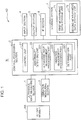
- FIG. 1 is a block diagram showing a configuration of a rotating machine including a rotating machine abnormality detection device according to the embodiment.
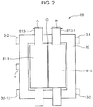
- FIG. 2 is a schematic top view of an example of a rotary member in the rotating machine shown in FIG. 1 .
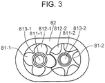
- FIG. 3 is a schematic sectional view of the rotary member shown in FIG. 2 .
- a rotating machine M includes a rotary member rotatable about a predetermined axis and, in the present embodiment, a rotating machine abnormality detection device AD for detecting an abnormality in the rotary member RB, as shown in FIG. 1 .
- the rotating machine abnormality detection device AD includes, for example, as shown in FIG. 1 , an ultrasonic wave measuring section 1, and a control processing section 2 having an abnormality detecting unit 22.
- the rotating machine abnormality detection device AD further includes a vibration measuring section 3, an input section 4, an output section 5, an interface section (IF section) 6, and a storage section 7.
- the rotating machine M including the rotating machine abnormality detection device AD may be any device including the rotary member RB, such as an electric motor, a generator, a compressor or a pump, but here, the rotating machine M in the form of a compressor will be described as an example.
- the rotating machine M in the form of a compressor includes the rotary member RB functioning as a compressor for pressure feeding fluid, and an unillustrated peripheral device for rotationally driving the rotary member RB.
- the rotary member RB includes, for example, a pair of first and second sub rotary members 81-1 and 81-2 defining a predetermined gap G therebetween and engageable with each other, and a casing 82 housing the first and second sub rotary members 81-1 and 81-2, as shown in FIGS. 2 and 3 .
- the first sub rotary member 81-1 serves as a male rotor in the compressor, and roughly includes a first sub rotary member body 811-1, a plurality of projecting portions 812-1 formed on a circumferential surface of the first sub rotary member body, and a first rotary shaft 813-1 coaxial with the first sub rotary member body 811-1.
- Such first sub rotary member 81-1 is driven to rotate, for example, counterclockwise (in the direction of the arrow A) about the first rotary shaft 813-1.
- the second sub rotary member 81-2 serves as a female rotor in the compressor, and roughly includes a second sub rotary member body 811-2, a plurality of recesses 812-2 formed on a circumferential surface of the second sub rotary member body, and a second rotary shaft 813-2 coaxial with the second sub rotary member body 811-2.
- Such second sub rotary member 81-2 is driven to rotate, for example, clockwise (in the direction of the arrow B) about the second rotary shaft 813-2.
- the plurality of projecting portions 812-1 formed on the circumferential surface of the first sub rotary member 81-1 will be referred to as “the projecting portions 812-1” and each one of the plurality of projecting portions 812-1 will be referred to as “projecting portion 812-1".
- the plurality of recessed portions 812-2 formed on the circumferential surface of the second sub rotary member 81-2 will be referred to as “the recessed portions 812-2" and each one of the plurality of recessed portions 812-2 will be referred to as "recessed portion 812-2".
- the first sub rotary member 81-1 rotates counterclockwise and the second sub rotary member 81-2 rotates clockwise, so that corresponding ones of the projecting portions 812-1 and the recessed portions 812-2 successively engage with each other.
- a counterclockwise turn of the first sub rotary member 81-1 and a clockwise turn of the second sub rotary member 81-2 allow one projecting portion 812-1 and one recessed portion 812-2 to engage with each other
- respective further turns of the sub rotary members 81-1 and 81-2 cause disengagement and allow the next projecting portion 812-1 and recessed projection 812-2 to engage with each other
- respective further turns of the sub rotary members 81-1 and 81-2 cause disengagement and allow the ones after the next projecting portion 812-1 and recessed projection 812-2 to engage with each other. This is repeated to compress fluid.
- the projecting portion 812-1 In the engagement between the projecting portion 812-1 and the recessed portion 812-2, the projecting portion 812-1 is placed in the recessed portion 812-2, but in the normal state, the projecting portion 812-1 and the recessed portion 812-2 are not in contact with each other and define the predetermined gap G therebetween.
- a contact between the projecting portion 812-1 and the recessed portion 812-2 means a contact between the first and second sub rotary members 81-1 and 81-2, which is an abnormal state.
- the casing 82 is in the form of a hollow cylinder having an oval shape in cross section, and having a space for accommodating the first and second sub rotary members 81-1 and 81-2 adjacently arranged with respective axes extending in parallel with each other and at a predetermined space from the inner circumferential surface of the casing 82.
- the casing 82 is formed with an unillustrated flow inlet for receiving fluid to be compressed at one end in an axial direction of the first and second sub rotary members 81-1 and 81-2, and an unillustrated flow outlet for discharging fluid compressed by the first and second sub rotary members 81-1 and 81-2 at the other end.
- an ultrasonic measuring section 1 is mounted at a predetermined first position and a vibration measuring section 3 (vibration measuring unit 3-1) is mounted at a predetermined second position on the outer surface of the casing 82.
- the ultrasonic wave measuring section 1 may include a plurality of ultrasonic wave measuring units mounted at different positions on the casing 82
- the vibration measuring section 3 may include a plurality of vibration measuring units mounted at different positions on the casing 82.
- FIG. 2 shows three vibration measuring units 3-2 to 3-4 indicated by dashed lines, in addition to the above-mentioned vibration measuring unit 3-1.
- the ultrasonic wave measuring section 1 is a device that is connected to the control processing section 2, and measures a vibration in an ultrasonic wave band (at a frequency from 100 kHz to 1MHz, for example) caused by the rotary member RB in order to detect an abnormality occurring in the rotating machine M, in particular, in the rotary member RB, the ultrasonic wave measuring section 1 being in the form of an AE (Acoustic Emission) sensor, for example.
- AE Acoustic Emission
- the ultrasonic wave measuring section 1 including the AE sensor detects and measures an elastic wave in the ultrasonic wave band caused by the rotary member RB due to an abnormality such as a contact.
- First measurement data obtained by the ultrasonic wave measuring section 1 is outputted to the control processing section 2. More specifically, the ultrasonic wave measuring section 1 detects a vibration in the ultrasonic wave band and outputs to the control processing section 2 a measurement result of the vibration in the ultrasonic wave band as first measurement data.
- the control processing section 2 samples the first measurement data inputted from the ultrasonic wave measuring section 1 at predetermined first time intervals (at first sampling intervals). Consequently, the control processing section 2 obtains chronological first measurement data successive at the first sampling intervals.
- the vibration measuring section 3 is a device that is connected to the control processing section 2, and measures a vibration in an audible wave band caused by the rotary member RB in order to detect an abnormality occurring in the rotating machine M, in particular, in the rotary member RB, the vibration measuring section 3 being in the form of an accelerometer, for example.
- the vibration measuring section 3 including the accelerometer detects and measures an elastic wave in the audible band caused by the rotary member RB due to an abnormality such as a contact.
- Second measurement data obtained by the vibration measuring section 3 is outputted to the control processing section 2. More specifically, the vibration measuring section 3 detects a vibration in the audible band and outputs to the control processing section 2 a measurement result of the vibration in the audible band as second measurement data.
- the control processing section 2 samples the second measurement data inputted from the vibration measuring section 3 at predetermined second time intervals (at second sampling intervals). Consequently, the control processing section 2 obtains chronological second measurement data successive at the second sampling intervals.
- the first sampling interval and the second sampling interval may be equal to or different from each other.
- the input section 4 is a device that is connected to the control processing section 2 and inputs, to the rotating machine abnormality detection device AD (rotating machine M), various kinds of commands such as a command instructing start of abnormality detection, and various kinds of data necessary for detecting an abnormal input of an identifier or the like in the rotating machine M (or in the rotary member RB) serving as the subject of abnormality detection, for example.
- Examples of the input section 4 include a plurality of input switches to which predetermined functions are respectively assigned, a keyboard, a mouse, and the like.
- the output section 5 is a device that is connected to the control processing section 2 and outputs a command or data inputted from the input section 4, and various results detected or measured by the rotating machine abnormality detection device AD, according to control by the control processing section 2.
- Examples of the output section 5 include a display device such as a CRT display, a LCD, and an organic EL display, a printing device such as a printer, and the like.
- the input section 4 and the output section 5 may constitute a touch panel.
- the input section 4 is, for example, in the form of a position input device of a resistive film type, an electrostatic capacitance type or the like that detects and inputs an operation position
- the output section 5 is in the form of a display device.
- the position input device is provided on a display surface of the display device, and when one or a plurality of input content candidates that can be inputted is displayed on the display device and a user touches a display position where a desired input content is displayed, the position input device detects the touched position and the display content displayed on the detected position is inputted to the rotating machine abnormality detection device AD (rotating machine M) as a content inputted by the user's operation. Since such a touch panel is easy for a user to intuitively understand input operation, a rotating machine abnormality detection device AD (rotating machine M) easy to be handled by a user can be provided.
- the IF section 6 is a circuit that is connected to the control processing section 2 and inputs and outputs data to and from an external device according to control by the control processing section 2.
- Examples of the IF section 6 include a serial communication type interface circuit using the RS-232C, an interface circuit using the USB (Universal Serial Bus) standard, and the like.
- the storage section 7 is connected to the control processing section 2, and stores a control program for causing each section of the rotating machine abnormality detection device AD to operate in accordance with the respective function according to control by the control processing section 2, various programs such as a rotating machine abnormality detection program for detecting an abnormality in the rotary machine M, information necessary for execution of each program, and the like, the storage section 7 also serving as a so-called working memory for the control processing section 2.
- the storage section 7 includes, for example, a non-volatile storage element such as ROM (Read Only Memory) and a rewritable non-volatile storage element such as EEPROM (Electrically Erasable Programmable Read Only Memory) for storing the above-mentioned programs and information necessary therefor, a volatile storage element such as RAM which is to serve as a working memory, and a peripheral circuit.
- a non-volatile storage element such as ROM (Read Only Memory) and a rewritable non-volatile storage element such as EEPROM (Electrically Erasable Programmable Read Only Memory) for storing the above-mentioned programs and information necessary therefor
- EEPROM Electrically Erasable Programmable Read Only Memory
- the storage section 7 functionally includes a first measurement data storage unit 71 for storing first measurement data obtained by the ultrasonic wave measuring section 1 and data obtained by performing a predetermined information processing task on the first measurement data as described later, and a second measurement data storage unit 72 for storing second measurement data obtained by the vibration measuring section 3 and data obtained by performing a predetermined information processing task on the second measurement as described later.
- the storage section 7 may further include a relatively large-capacity storage device such as a hard disk for storing first and second measurement data obtained by the ultrasonic wave measuring section 1 and the vibration measuring section 3, respectively, and various types of data obtained by performing respective predetermined information processing tasks on the first and second measurement data.
- the control processing section 2 controls each section of the rotating machine abnormality detection device AD in accordance with the respective function of each section in order to detect an abnormality in the rotating machine M and includes, for example, a microprocessor such as CPU (Central Processing Unit) and a peripheral circuit.
- the control processing section 2 executes a program to functionally configure a control unit 21 and an abnormality detecting unit 22.
- the control unit 21 controls each section of the rotating machine abnormality detection device AD in accordance with the respective function of each section to thereby perform overall control of the rotating machine abnormality detection device AD.
- the abnormality detecting unit 22 detects an initial abnormality in the rotating machine M based on first measurement data obtained by the ultrasonic wave measuring section 1.
- the abnormality detecting unit 22 calculates a first frequency spectrum of the first measurement data obtained by the ultrasonic wave measuring section 1, and calculates a specific first feature amount in the first frequency spectrum of the first measurement data to detect an initial abnormality in the rotating machine M based on the first feature amount.
- the first feature amount is an amount (value) that indicates an event occurring in the first frequency spectrum in relation to an initial abnormality in the rotating machine M.
- the first feature amount is, for example, the integrated value within a predetermined frequency range of the first frequency spectrum of the first measurement data.
- the abnormality detecting unit 22 calculates the integrated value (integral area expressed as a quantitative value) within a predetermined frequency range of the first frequency spectrum of the first measurement data, and compares the calculated integrated value with a predetermined threshold value Th1 to determine that there is an initial abnormality in the rotating machine M when the integrated value is equal to or greater than the threshold value Th1.
- the abnormality detecting unit 22 further determines, after detecting an initial abnormality, at least one of an abnormality type and an abnormality degree based on second measurement data obtained by the vibration measuring section 3.
- the abnormality detecting unit 22 determines at least one of an abnormality type and an abnormality degree based on second measurement data (pre-second measurement data) obtained by the vibration measuring section 3 before the detection of an initial abnormality and second measurement data (post-second measurement data) obtained by the vibration measuring section 3 after the detection of the initial abnormality.
- the pre-second measurement data may be obtained at any time before the detection of an initial abnormality, for example, immediately before the detection of the initial abnormality or at a predetermined time before the detection of the initial abnormality.
- the pre-second measurement data are dealt as second measurement data obtained when the rotating machine M is in the normal state.
- the post-second measurement data may be obtained at any time after the detection of an initial abnormality, such as immediately after the detection of the initial abnormality or at a predetermined time after the detection of the initial abnormality.
- the post-second measurement data is dealt as second measurement data obtained when the rotating machine M is in an abnormal state (when the rotating machine M is not in the normal state). More preferably, the abnormality detecting unit 22 calculates a specific second feature amount in the pre-second measurement data and a third feature amount in the post-second measurement data that is of the same type as the second feature amount, to determine at least one of an abnormality type and an abnormal degree based on the second and third feature amounts.
- the second and third feature amounts are amounts (values) that indicate an event occurring in the pre-second measurement data and post-second measurement data in relation to an abnormality in the rotating machine M.
- the second feature amount is for a second frequency spectrum of the pre-second measurement data obtained by the vibration measuring section 3 before the detection of an initial abnormality
- the third feature amount is for a third frequency spectrum of the post-second measurement data obtained by the vibration measuring section 3 after the detection of the initial abnormality.
- the abnormality detecting unit 22 compares the second frequency spectrum of the second measurement data with the third frequency spectrum of the second measurement data to determine at least one of an abnormality type and an abnormality degree based on a comparison result.
- the mean square or the root mean square (RMS) may be used.
- abnormality types include a first abnormality in which the sub rotary members 81-1 and 81-2 come into contact with each other, and a second abnormality in which at least one of the sub rotary members 81-1 and 81-2 comes into contact with the casing 82.
- the abnormality detecting unit 22 functionally includes, for example, an ultrasonic wave measurement processing part 221, a vibration measurement processing part 222, and a determination part 223, as shown in FIG. 1 .
- the ultrasonic wave measurement processing part 221 performs the above-mentioned processing task on first measurement data obtained by the ultrasonic wave measuring section 1.
- the vibration measurement processing part 222 performs the above-described processing task on second measurement data obtained by the vibration measuring section 3.
- the determination part 223 determines the presence/absence of an initial abnormality in the rotating machine M based on a processing result of the ultrasonic wave measurement processing part 221 to thereby detect an initial abnormality in the rotating machine M, and determines at least one of an abnormality type and an abnormality degree based on a processing result of the vibration measurement processing part 222.
- control processing section 2 the input section 4, the output section 5, the IF section 6, and the storage section 7 in the rotating machine abnormality detection device AD can be realized by a computer such as a desktop, laptop, tablet or other type of personal computer.
- FIG. 4 is a flowchart of the operation of the rotating machine abnormality detection device in the embodiment.
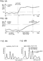
- FIGS. 5A and 5B are graphs showing the chronological change in specific feature amounts.
- FIG. 5A shows the chronological change in the first feature amount with the horizontal axis representing time and the vertical axis representing magnitude (level) of the first feature amount.
- FIG. 5B shows the chronological change in the second and third feature amounts with the horizontal axis representing time and the vertical axis representing magnitude (level) of the second and third feature amounts.
- FIGS. 6A and 6B are graphs for explaining an example of abnormality diagnosis.
- FIG. 5A shows the chronological change in the first feature amount with the horizontal axis representing time and the vertical axis representing magnitude (level) of the first feature amount.
- FIG. 5B shows the chronological change in the second and third feature amounts with the horizontal axis representing time and the vertical axis representing magnitude (level) of the second and third feature amounts.
- FIGS. 6A and 6B are graphs for explaining an example of
- FIG. 6A shows a frequency spectrum of second measurement data (an example of the second frequency spectrum of the pre-second measurement data) obtained when the rotating machine M is considered to be in the normal state with no abnormality in the rotating machine M being found, the horizontal axis of the graph representing frequency and the vertical axis of the graph representing intensity.
- FIG. 6B shows a frequency spectrum of second measurement data (an example of the third frequency spectrum of the post-second measurement data) obtained when the rotating machine M is considered to be in an abnormal state due to an abnormality occurring in the rotating machine M, the horizontal axis of the graph representing frequency and the vertical axis of the graph representing intensity.
- the rotating machine abnormality detection device AD Upon start of the operation of the rotating machine M caused by, for example, a user's manipulation of an unillustrated activation switch, the rotating machine abnormality detection device AD executes the rotating machine abnormality detection program.
- the execution of the rotating machine abnormality detection program causes the control unit 21 and the abnormality detecting unit 22 to run on the control processing section 2, causes the first measurement data storage unit 71 and the second measurement data storage unit 72 to run on the storage section 7, and causes the ultrasonic wave measurement processing part 221, the vibration measurement processing part 222, and the determination part 223 to run on the abnormality detecting unit 22.
- the rotating machine abnormality detection device AD then performs the following operation steps to detect an initial abnormality in the rotating machine M, an abnormality type and the like.
- the ultrasonic wave measuring section 1 detects a vibration in the ultrasonic wave band in the rotating machine M and outputs a measurement result of the vibration in the ultrasonic wave band as first measurement data to the control processing section 2, and the vibration measuring section 3 detects a vibration in the audible band in the rotating machine M and outputs a measurement result of the vibration in the audible band as second measurement data to the control processing section 2.
- the ultrasonic wave measurement processing part 221 of the abnormality detecting unit 22 samples the first measurement data inputted from the ultrasonic wave measuring section 1 at the first sampling intervals and stores them in the first measurement data storage unit 71 of the storage section 7. In this manner, the first measurement data are successively measured at the first sampling intervals, and stored in the storage unit 71.
- the vibration measurement processing part 222 of the abnormality detecting unit 22 samples the second measurement data inputted from the vibration measuring section 3 at the second sampling intervals and stores them in the second measurement data storage unit 72 of the storage section 7. In this manner, the second measurement data are successively measured at the second sampling intervals, and stored in the storage unit 72.
- the ultrasonic wave measurement processing part 221 performs Fast Fourier Transform (FFT) on plural sets of first measurement data stored in the first measurement data storage unit 71, the sets of data including the most recently measured first measurement data and being arranged in chronological order within a predetermined time period (first time period) (i.e. each set of first measurement data obtained within the first time period ending at the most recent measurement time point), to calculate the first frequency spectrum and the first feature amount in the first frequency spectrum of the first measurement data.
- the ultrasonic wave measurement processing part 221 stores the calculated first frequency spectrum and the first feature amount in the first measurement data storage unit 71. More specifically, in the present embodiment, the ultrasonic wave measurement processing part 221 calculates, as the first feature amount, the integrated value within the above-mentioned frequency range of the first frequency spectrum of the first measurement data.
- FFT Fast Fourier Transform
- the determination part 223 of the abnormality detecting unit 22 determines the presence/absence of an initial abnormality in the rotating machine M based on the first feature amount calculated at step S3. More specifically, in the present embodiment, the determination part 223 compares the integrated value calculated as the first feature amount at step S3 with the threshold value Th1. When, as a result of the comparison, the integrated value is equal to or greater than the threshold value Th1 (Yes), the determination part 223 determines that there is an initial abnormality in the rotating machine M and causes the vibration measurement processing part 222 to perform step S5. On the other hand, when, as a result of the comparison, the integrated value is less than the threshold value Th1 (No), the determination part 223 determines that there is no initial abnormality in the rotating machine M and returns the operation to step S1.
- the initial abnormality is preferred to include the time of occurrence of an abnormality.
- the integrated value is compared with the threshold value Th1, and the time point at which the integrated value becomes equal to or greater than the threshold value Th1 is regarded as the time of occurrence of an abnormality.
- the rotating machine abnormality detection device AD can detect the time of occurrence (the occurrence timing) of an abnormality in the rotating machine M.
- the determination part 223 may output the determination result to the output section 5. For example, when the output section 5 is in the form of a display device, the determination part 223 outputs a message indicating that there is an initial abnormality in the rotating machine M (such as a message reading "an initial abnormality has occurred") to the output section 5. Alternatively, when the output section 5 is in the form of a sound generator such as speaker or buzzer, for example, the determination part 223 outputs to the output section 5, an alarm (warning sound) indicating that there is an initial abnormality in the rotating machine M.
- a sound generator such as speaker or buzzer
- the determination part 223 outputs to the output section 5, an alarm beam (warning beam) indicating that there is an initial abnormality in the rotating machine M.
- a light source such as light-emitting diode (LED)
- the determination part 223 outputs to the output section 5, an alarm beam (warning beam) indicating that there is an initial abnormality in the rotating machine M.
- step S5 is performed.
- the vibration measurement processing part 222 calculates the second feature amount in pre-second measurement data obtained by the vibration measuring section 3 before the detection of the initial abnormality. More specifically, the vibration measurement processing part 222 performs FFT on plural sets of pre-second measurement data stored in the second measurement data storage unit 72 and arranged in chronological order within a predetermined time period (pre-time period), to calculate the second frequency spectrum as the second feature amount. Thereafter, the vibration measurement processing part 222 stores the calculated second frequency spectrum (second feature amount) in the second measurement data storage unit 72.
- the pre-second measurement data are, as mentioned above, second measurement data obtained when the rotating machine M is in the normal state and, therefore, the second frequency spectrum (second feature amount) calculated based on the pre-second measurement data obtained in the normal state is dealt as a normal pattern.
- the storage region of the second measurement data storage unit 72 for storing the pre-second measurement data is preferred to be a ring buffer having a capacity to store the pre-second measurement data within the pre-time period (for example, several minutes such as one or ten minutes).
- the vibration measurement processing part 222 upon determination that an initial abnormality is detected at step S4, the vibration measurement processing part 222 performs FFT on all data stored in the storage region of the second measurement data storage unit 72 for storing the pre-second measurement data to thereby automatically calculate the second frequency spectrum as the second feature amount without performing screening of the second measurement data stored in the second measurement data storage unit 72.
- the storage region of the second measurement data storage unit 72 for storing pre-second measurement data may use the First-In, First-Out (FIFO) Method.
- the vibration measurement processing part 222 calculates the third feature amount in post-second measurement data obtained by the vibration measuring section 3 after the detection of the initial abnormality. More specifically, the vibration measurement processing part 222 performs, upon elapse of a predetermine time period (post-time period) after the detection of the initial abnormality, FFT on plural sets of post-second measurement data stored in the second measurement data storage unit 72 and arranged in chronological order within the post-time period, to calculate the third frequency spectrum for the third feature amount. Thereafter, the vibration measurement processing part 222 stores the calculated third frequency spectrum (third feature amount) in the second measurement data storage unit 72.
- the pre-third measurement data are, as mentioned above, second measurement data obtained when the rotating machine M is not in the normal state but in the abnormal state, and therefore, the third frequency spectrum (third feature amount) calculated based on the second measurement data obtained in the abnormal state is dealt as an abnormal pattern.
- pre-time period and the post-time period may be equal to or different from each other.
- the pre-time period and the post-time period are preferred to be equal to each other for relative comparison and, furthermore, for standardization.
- the determination part 223 compares the second frequency spectrum of the second measurement data calculated at step S5 and the third frequency spectrum of the second measurement data calculated at step S6 and, subsequently at step S8, the determination part 223 determines at least one of, in the present embodiment, both of an abnormality type and an abnormality degree based on a comparison result at step S7.
- comparison results between second frequency spectrums and third frequency spectrums of second measurement data are obtained according to abnormality types and degrees in advance, and correspondences between the abnormality types and degrees and the comparison results are stored in the storage section 7 in advance.
- the abnormality types include, in the present embodiment, the first abnormality in which the sub rotary members 81-1 and 81-2 come into contact with each other, and the second abnormality in which at least one of the sub rotary members 81-1 and 81-2 comes into contact with the casing 82.
- the determination part 223 refers to the correspondences stored in the storage section 7 to determine an abnormality type and an abnormality degree based on the comparison result at step S7.
- the determination part 223 When, as a result of the determination, the first abnormality is determined (determination 1), the determination part 223 performs step S9 of outputting to the output section 5 information indicating occurrence of the first abnormality in which the sub rotary members 81-1 and 81-2 come into contact with each other, and the degree of the abnormality, and then terminates the operation.
- the second abnormality is determined (determination 2)
- the determination part 223 performs step S10 of outputting to the output section 5 information indicating occurrence of the second abnormality in which at least one of the sub rotary members 81-1 and 81-2 comes into contact with the casing 82, and the degree of the abnormality, and then terminates the operation.
- the determination part 223 performs step S11 of outputting to the output section 5 information indicating occurrence of another abnormality different from the first and second abnormalities, and terminates the operation.
- the another abnormality a slight contact in a bearing can be considered.
- the abnormalities in the present embodiment include abnormalities in the rotating machine M due to a contact.
- the rotational period of the first sub rotary member 81-1 is CT1
- the rotational period of the second sub rotary member 81-2 is CT2
- the ratio between the number of projecting portions 812-1 of the first sub rotary member 81-1 and the number of recessed portions 812-2 of the second sub rotary member 81-2 is a:b
- the intensity of the frequency corresponding to the period of CT1 in the third frequency spectrum is different from that in the second frequency spectrum.
- a projecting portion of the second sub rotary member 81-2 that defines a recessed portion 812-2 comes into contact with the casing 82 in the second abnormality, the intensity of the frequency corresponding to the period of CT2 is different from that in the second frequency spectrum. Therefore, for example, it is possible to determine an abnormality type by comparing the second frequency spectrum in the normal pattern and the third frequency spectrum in the abnormal pattern and finding the frequency that has meaningfully different intensities between the second and third frequency spectrums.
- the third frequency spectrum has a high overall intensity and the frequency having the maximum intensity (at a peak) shifted to a high tone range as compared to the second frequency spectrum. Therefore, for example, it is possible to determine an abnormality degree by comparing the second frequency spectrum in the normal pattern and the third frequency spectrum in the abnormal pattern and finding a meaningful difference in the maximum intensity. In this case, the abnormality degree increases as the difference in the maximum intensity increases. Further in another example, it is possible to determine an abnormality degree by comparing the second frequency spectrum in the normal pattern and the third frequency spectrum in the abnormal pattern and finding a meaningful shift amount of the frequency having the maximum intensity.
- the abnormality degree increases as the frequency shift amount increases.
- the abnormality degree increases as the correlation value decreases.
- a deviation may be calculated as the reciprocal of the correlation value to determine an abnormality degree based on the deviation. In this case, the abnormality value increases as the deviation increases.
- the abnormality detecting unit 22 determines, after the detection of an initial abnormality, at least one of, in the present embodiment, both of an abnormality type and an abnormal degree based on pre-second measurement data obtained by the vibration measuring section 3 before the detection of the initial abnormality and post-second measurement data obtained by the vibration measuring section 3 after the detection of the initial abnormality (steps S5 to S11).
- both an abnormality type and an abnormality degree are determined, but it may be configured to determine at least one of them.
- the vibration measuring section 3 includes a plurality of vibration measuring units
- second measurement data obtained by each vibration measuring unit 3 are subjected to the above-described steps S5 to S11. Thereafter, determination based on each second measurement data is outputted to the output section 5.
- a contact position can also be estimated using the so-called triangulation based on the difference in time required for the same vibration in the audible band to reach each vibration measuring unit 3, the vibration being caused by the rotary member RB.
- the above-described steps can be explained by the following example.
- the first feature amount is repeatedly calculated from the time T0 after the start of operation of the rotating machine M, and in occurrence of an abnormality in the rotating machine M, the first feature amount starts to increase and becomes equal to or greater than the threshold value Th1 at the time T1 to allow determination of occurrence of an initial abnormality in the rotating machine M.
- the above-described step S2 is also performed.
- the vibration measurement processing part 222 may perform a similar operation to that of the ultrasonic measurement processing part 221. Specifically, the vibration measurement processing part 222 performs FFT on plural sets of second measurement data stored in the second measurement data storage unit 72, the sets of data including the most recently measured second measurement data and being arranged in chronological order within the pre-time period (i.e. each set of second measurement data obtained within the pre-time period ending at the most recent measuring time point), to calculate the second frequency spectrum, and the integrated value within a predetermined second frequency range of the calculated second frequency spectrum of the second measurement data as a specific fourth feature amount.
- the chronological change in the fourth feature amount is shown in FIG. 5B .
- the above-described step S5 is performed to calculate the second frequency spectrum of second measurement data as the second feature amount.
- An example of the second frequency spectrum (second feature amount) of second measurement data is shown in FIG. 6A .
- the above-described step S6 is performed to calculate the third frequency spectrum of second measurement data as the third feature amount.
- An example of the second frequency spectrum (third feature amount) of second measurement data is shown in FIG. 6B .
- the third frequency spectrum in the abnormal pattern has a high overall intensity, a different maximum intensity, and the frequency having the maximum intensity shifted to a high tone range as compared to the second frequency spectrum in the normal pattern. This corresponds to a case where the noise of the rotating machine M heard via a listening rod gradually increases in volume and slightly changes in tone as an abnormality develops.
- steps S7 and S8 are performed to compare, in this example, the second frequency spectrum in the normal pattern shown in FIG. 6A and the third frequency spectrum in the abnormal pattern shown in FIG. 6B to determine an abnormality type and an abnormality degree, and subsequently, the above-described step S9 or step S11 is performed according to a determination result, and then the operation is terminated.
- the rotating machine abnormality detection device AD and the rotating machine M include the ultrasonic wave measuring section 1 for measuring a vibration in the ultrasonic wave band caused by the rotary member RB.
- the ultrasonic wave measuring section 1 for measuring a vibration in the ultrasonic wave band caused by the rotary member RB.
- a contact between the first and second sub rotary members 81-1 and 81-2 in the compressor may generate heat to cause thermal expansion of the first and second sub rotary members 81-1 and 81-2, which may lead to a relatively serious accident. Therefore, the detection of an initial abnormality in the rotating machine M is advantageous.
- the rotating machine M In the rotating machine M, the rotary member RB, i.e. the first and second sub rotary members 81-1 and 81-2 in the present embodiment, rotates at a predetermined speed. Therefore, a change in the intensity of a specific frequency, a shift of the frequency that is at a peak, or the like occurs in occurrence of an abnormality as described above, which changes the shape (profile or pattern) of the frequency spectrum. Therefore, the rotating machine abnormality detection device AD and the rotating machine M according to the present embodiment can properly detect an initial abnormality because an initial abnormality in the rotating machine M is detected based on the first feature amount in the first frequency spectrum of first measurement data.
- the rotating machine abnormality detection device AD and the rotating machine M can properly detect an initial abnormality in the rotating machine M because an initial abnormality is detected based on a comparison result between the integrated value and the threshold value Th1.
- the rotating machine abnormality detection device AD and the rotating machine M according to the present embodiment perform the above-described determination step after the detection of an initial abnormality, which can reduce redundant operational steps.
- the rotating machine abnormality detection device AD and the rotating machine M according to the present embodiment further include the vibration measuring section 3 for measuring a vibration in the audible band caused by the rotary member RB. This makes it possible, in accordance with the ideas conceived by the inventors of the present invention, to determine at least one of an abnormality type and an abnormality degree in the rotating machine based on at least one of the manner of change and the intensity of second measurement data obtained by the vibration measuring section 3.
- the rotating machine abnormality detection device AD and the rotating machine M can properly determine at least one of (in the present embodiment, both of) an abnormality type and an abnormality degree because at least one of (in the present embodiment, both of) an abnormality type and an abnormality degree is determined based on these two sets of second measurement data.
- the rotating machine abnormality detection device AD and the rotating machine M can properly determine at least one of (in the present embodiment, both of) an abnormality type and an abnormality degree because at least one of (in the present embodiment, both of) an abnormality type and an abnormality degree is determined based on the specific second and third feature amounts of the same type of the above-mentioned two sets of second measurement data.
- the rotating machine abnormality detection device AD and the rotating machine M according to the present embodiment can properly determine at least one of (in the present embodiment, both of) an abnormality type and an abnormality degree because at least one of (in the present embodiment, both of) an abnormality type and an abnormality degree is determined based on a result of comparison between these second and third frequency spectrums.
- the rotary member RB of the rotating machine M includes the pair of first and second sub rotary members 81-1 and 81-2, but the number of sub rotary members is not limited to two.
- the rotary member RB may be configured to include a single (one) sub rotary member or a plurality of sub rotary members.
- a rotating machine abnormality detection device for detecting an abnormality in a rotating machine including a rotary member rotatable about a predetermined axis, comprising: an ultrasonic wave measuring section for measuring a vibration in an ultrasonic wave band caused by the rotary member; and an abnormality detecting section for detecting an initial abnormality in the rotating machine based on first measurement data obtained by the ultrasonic wave measuring section.
- the present inventors consider that, in occurrence of an abnormality in the rotating machine, a vibration in the ultrasonic wave band (ultrasonic wave range) occurs at its initial stage and a vibration in the audible band (audible range) also occurs as the abnormality develops, and that it is possible, after detection of a signal change in the ultrasonic wave range (after detection of an initial abnormality), to determine an abnormality type and the like by reviewing a measurement result within a range over several seconds or minutes before the detection time point (including a range after the detection time point).
- the rotating machine abnormality detection device includes the ultrasonic wave measuring section for measuring a vibration in the ultrasonic wave band caused by the rotary member, which makes it possible to detect an initial abnormality in the rotating machine based on first measurement data obtained as a result of the measurement.
- the ultrasonic wave band includes vibrations at frequencies that are so high that people having a normal hearing ability do not hear them, such as vibrations at a frequency of 100kHz or more.
- the audible band includes vibrations at frequencies audible by people having a normal hearing ability, such as vibrations at a frequency in the range between 20Hz and 20 kHz.
- the abnormality detecting section calculates a first frequency spectrum of the first measurement data obtained by the ultrasonic wave measuring section, and calculates a specific first feature amount in the first frequency spectrum of the first measurement data to detect an initial abnormality in the rotating machine based on the first feature amount.
- the rotary member rotates at a predetermined speed. Therefore, a change in the intensity of a specific frequency, a shift of the frequency that is at a peak, or the like occurs in occurrence of an abnormality as described above, which changes the shape (profile or pattern) of the frequency spectrum. Therefore, the above-described rotating machine abnormality detection device can properly detect an initial abnormality because an initial abnormality in the rotating machine is detected based on the specific first feature amount in the first frequency spectrum.
- the first feature amount is an integrated value within a predetermined frequency range of the first frequency spectrum of the first measurement data
- the abnormality detecting section compares the calculated integrated value with a predetermined threshold value, and determines that there is an initial abnormality in the rotating machine when the integrated value is equal to or greater than the threshold value.
- the above-described rotating machine abnormality detection device can properly detect an initial abnormality in the rotating machine because an initial abnormality is detected based on a comparison result between the integrated value and the predetermined threshold value.
- the initial abnormality is preferred to include the time of occurrence of an abnormality.
- Such rotating machine abnormality detection devices can detect the time of occurrence (the occurrence timing) of an abnormality in the rotating machine by comparing the calculated integrated value with the predetermined threshold value and determining the time point at which the integrated value becomes equal to or greater than the threshold value as the time of occurrence of an abnormality.
- a vibration measuring section for measuring a vibration in an audible band caused by the rotary member is further included, and the abnormality detecting section determines, after detecting an initial abnormality, at least one of an abnormality type and an abnormality degree based on second measurement data obtained by the vibration measuring section.
- Such rotating machine abnormality detection device performs the determination after the detection of an initial abnormality, which can reduce redundant operational steps. Further, based on studies made by the present inventors, it is considered, as described above, that in occurrence of an abnormality in the rotating machine, the manner of change in a vibration in the audible band differs according to the type of the abnormality and the intensity of the vibration in the audible band increases as the abnormality develops.
- the above-described rotating machine abnormality detection device further includes the vibration measuring section for measuring a vibration in the audible band caused by the rotary member and, which makes it possible to detect at least one of an abnormality type and an abnormality degree in the rotating machine based on at least one of the manner of change and the intensity of second measurement data obtained by the vibration measuring section.
- the abnormality detecting section determines at least one of an abnormality type and an abnormality degree based on second measurement data obtained by the vibration measuring section before the detection of an initial abnormality and second measurement data obtained by the vibration measuring section after the detection of the initial abnormality.
- the second measurement data obtained by the vibration measuring section before the detection of an initial abnormality reflects the normal state of the rotating machine in which no abnormality occurs in the rotating machine and, on the other hand, the second measurement data obtained by the vibration measuring section after the detection of the initial abnormality reflects the abnormal state of the rotating machine in which an abnormality occurs in the rotating machine. Therefore, the above-described rotating machine abnormality detection device can properly determine at least one of an abnormality type and an abnormality degree because at least one of an abnormality type and an abnormality degree is determined based on these two sets of second measurement data.
- the abnormality detecting section calculates a specific second feature amount in the second measurement data obtained by the vibration measuring section before the detection of an initial abnormality and a third feature amount in the second measurement data that is of the same type as the second feature amount and obtained by the vibration measuring section after the detection of the initial abnormality, to determine at least one of an abnormality type and an abnormality degree based on the second and third feature amounts.
- the above-described rotating machine abnormality detection device can properly determine at least one of an abnormality type and an abnormality degree because at least one of an abnormality type and an abnormality degree is determined based on the specific second and third feature amounts of the same type of the above-mentioned two sets of second measurement data.
- the second feature amount is for a second frequency spectrum of the second measurement data obtained by the vibration measuring section before the detection of an initial abnormality
- the third feature amount is for a third frequency spectrum of the second measurement data obtained by the vibration measuring section after the detection of the initial abnormality
- the abnormality detecting section compares the second frequency spectrum of the second measurement data with the third frequency spectrum of the second measurement data to determine at least one of an abnormality type and an abnormality degree based on a comparison result.
- the above-described rotating machine abnormality detection device can properly determine at least one of an abnormality type and an abnormality degree because at least one of an abnormality type and an abnormality degree is determined based on a result of comparison between these second and third spectrums.
- the rotary member includes a pair of sub rotary members engageable with each other, and a casing housing the pair of sub rotary members, and abnormality types include a first abnormality in which the sub rotary members come into contact with each other, and a second abnormality in which at least one of the sub rotary members comes into contact with the casing.
- Such rotating machine abnormality detection device can distinguish between at least the first abnormality in which the sub rotary members come into contact with each other, and the second abnormality in which at least one of the sub rotary members comes into contact with the casing.
- a rotating machine includes any one of the above-described rotating machine abnormality detection devices.
- a rotating machine including any one of the above-described rotating machine abnormality detection devices is provided, the rotating machine being capable of detecting an initial abnormality.
- a rotating machine abnormality detection method for detecting an abnormality in a rotating machine including a rotary member rotatable about a predetermined axis, comprising: an ultrasonic wave measuring step of measuring a vibration in an ultrasonic wave band caused by the rotary member; and an abnormality detecting step of detecting an initial abnormality in the rotating machine based on first measurement data obtained in the ultrasonic wave measuring step.
- Such rotating machine abnormality detection method includes the ultrasonic wave measuring step of measuring a vibration in the ultrasonic wave band caused by the rotary member, which makes it possible to detect an initial abnormality in the rotating machine based on first measurement data obtained as a result of the measurement.
- the present invention can provide rotating machine abnormality detection device and method and a rotating machine.
Applications Claiming Priority (2)
| Application Number | Priority Date | Filing Date | Title |
|---|---|---|---|
| JP2014185873A JP6223935B2 (ja) | 2014-09-12 | 2014-09-12 | 回転機械異常検出装置および該方法ならびに回転機 |
| PCT/JP2015/073120 WO2016039088A1 (fr) | 2014-09-12 | 2015-08-18 | Dispositif et procédé de détection d'anomalie de machine rotative, et machine rotative |
Publications (3)
| Publication Number | Publication Date |
|---|---|
| EP3193155A1 true EP3193155A1 (fr) | 2017-07-19 |
| EP3193155A4 EP3193155A4 (fr) | 2018-05-16 |
| EP3193155B1 EP3193155B1 (fr) | 2020-12-23 |
Family
ID=55458846
Family Applications (1)
| Application Number | Title | Priority Date | Filing Date |
|---|---|---|---|
| EP15839521.0A Active EP3193155B1 (fr) | 2014-09-12 | 2015-08-18 | Dispositif et procédé de détection d'anomalie de machine rotative, et machine rotative |
Country Status (5)
| Country | Link |
|---|---|
| US (1) | US10247599B2 (fr) |
| EP (1) | EP3193155B1 (fr) |
| JP (1) | JP6223935B2 (fr) |
| CN (1) | CN106662504B (fr) |
| WO (1) | WO2016039088A1 (fr) |
Cited By (1)
| Publication number | Priority date | Publication date | Assignee | Title |
|---|---|---|---|---|
| EP3306284A1 (fr) * | 2016-10-10 | 2018-04-11 | Rolls-Royce plc | Procédé et système pour déterminer l'état d'une machine électrique |
Families Citing this family (10)
| Publication number | Priority date | Publication date | Assignee | Title |
|---|---|---|---|---|
| JP6523137B2 (ja) * | 2015-10-28 | 2019-05-29 | 株式会社神戸製鋼所 | 回転機の異常検知装置、回転機の異常検知方法、及び、回転機 |
| JP6630653B2 (ja) * | 2016-10-06 | 2020-01-15 | 株式会社神戸製鋼所 | 回転機異常検出装置および該方法ならびに回転機 |
| WO2019124237A1 (fr) * | 2017-12-21 | 2019-06-27 | 日立金属株式会社 | Dispositif et procédé de détection en ligne de fissures pour rouleau de laminage, et rouleau de laminage |
| JP6744342B2 (ja) * | 2018-02-13 | 2020-08-19 | ファナック株式会社 | 工作機械の制御装置 |
| JP6708676B2 (ja) * | 2018-02-27 | 2020-06-10 | ファナック株式会社 | 異常要因特定装置 |
| US10895873B2 (en) * | 2018-04-25 | 2021-01-19 | Aktiebolaget Skf | Machine health monitoring of rotating machinery |
| US20230024947A1 (en) * | 2020-01-14 | 2023-01-26 | Jfe Steel Corporation | Abnormality diagnosis system and abnormality diagnosis method |
| JP7075466B1 (ja) | 2020-11-17 | 2022-05-25 | 株式会社酉島製作所 | 振動機械の異常診断装置および異常診断方法 |
| JP2022081152A (ja) * | 2020-11-19 | 2022-05-31 | 株式会社ジェイテクト | 監視装置、集音装置及び監視方法 |
| JP2023012871A (ja) * | 2021-07-14 | 2023-01-26 | 株式会社神戸製鋼所 | 転がり軸受異常検出装置および転がり軸受異常検出方法 |
Family Cites Families (24)
| Publication number | Priority date | Publication date | Assignee | Title |
|---|---|---|---|---|
| US4237454A (en) * | 1979-01-29 | 1980-12-02 | General Electric Company | System for monitoring bearings and other rotating equipment |
| WO1981002785A1 (fr) * | 1980-03-26 | 1981-10-01 | Kawasaki Steel Co | Dispositif de controle pour une machine rotative |
| JPS58150859A (ja) | 1982-03-03 | 1983-09-07 | Hitachi Ltd | 回転体の亀裂診断装置 |
| JPS6219755A (ja) | 1985-07-19 | 1987-01-28 | Hitachi Ltd | Ae方式回転機異常診断システム |
| US5144840A (en) * | 1989-06-23 | 1992-09-08 | General Electric Company | Vibration detector and method for rotating shaft |
| US5058434A (en) * | 1990-02-27 | 1991-10-22 | Carl Schenck Ag | Process for early detection of damage to machine parts |
| JPH04106429A (ja) | 1990-08-28 | 1992-04-08 | Kobe Steel Ltd | 回転機械の異常診断装置 |
| JP2521548Y2 (ja) * | 1990-11-01 | 1996-12-25 | 三菱重工業株式会社 | 排気弁の故障診断装置 |
| JPH081380Y2 (ja) * | 1991-02-27 | 1996-01-17 | 三菱重工業株式会社 | 天井設置形空気調和機 |
| DE4229340C2 (de) * | 1992-09-04 | 1998-10-01 | Schenck Process Gmbh | Verfahren zur Früherkennung eines Risses in einer rotierenden Welle |
| JPH0843193A (ja) * | 1994-07-29 | 1996-02-16 | Toshiba Corp | 回転機械のラビング検知方法 |
| JPH08166330A (ja) | 1994-12-15 | 1996-06-25 | Hitachi Ltd | 回転機械の異常摺動診断方法とその装置、及び非接触型スクリュー圧縮機の異常摺動診断方法とその装置 |
| JP2001074616A (ja) | 1999-09-06 | 2001-03-23 | Mitsubishi Electric Corp | 回転機の異常診断装置 |
| JP2002181038A (ja) * | 2000-12-18 | 2002-06-26 | Mitsubishi Heavy Ind Ltd | 異常診断装置 |
| US20020181038A1 (en) * | 2001-06-01 | 2002-12-05 | Hait John N. | Photonic data stabilization |
| EP1548419B1 (fr) * | 2002-08-30 | 2013-07-24 | NSK Ltd. | Procede et dispositif de controle d'etat de materiel mecanique et dispositif de diagnostic d'anomalies |
| US20050072234A1 (en) * | 2003-05-20 | 2005-04-07 | Weidong Zhu | System and method for detecting structural damage |
| DE502006006469D1 (de) * | 2006-11-24 | 2010-04-29 | Groz Beckert Kg | Getriebe für einen Webschaftantrieb |
| JP5220181B2 (ja) * | 2008-03-28 | 2013-06-26 | テレフオンアクチーボラゲット エル エム エリクソン(パブル) | エンドツーエンドインタードメインルーティング |
| JP2010234403A (ja) * | 2009-03-31 | 2010-10-21 | Jfe Steel Corp | 圧延機の回転軸の異常診断装置および異常診断方法 |
| JP2012208045A (ja) | 2011-03-30 | 2012-10-25 | Chugoku Electric Power Co Inc:The | 聴診棒 |
| CN102564765A (zh) * | 2011-12-20 | 2012-07-11 | 浙江省电力试验研究院 | 一种汽轮发电机组动静碰摩轴向位置定位方法 |
| CN102519579B (zh) | 2011-12-20 | 2014-02-19 | 华北电力大学 | 汽轮机碰磨故障检测方法 |
| FR2987443B1 (fr) * | 2012-02-24 | 2014-03-07 | Snecma | Dispositif de detection d'anomalies par analyse acoustique d'une turbomachine d'aeronef |
-
2014
- 2014-09-12 JP JP2014185873A patent/JP6223935B2/ja active Active
-
2015
- 2015-08-18 CN CN201580042865.7A patent/CN106662504B/zh active Active
- 2015-08-18 EP EP15839521.0A patent/EP3193155B1/fr active Active
- 2015-08-18 WO PCT/JP2015/073120 patent/WO2016039088A1/fr active Application Filing
- 2015-08-18 US US15/328,308 patent/US10247599B2/en active Active
Cited By (2)
| Publication number | Priority date | Publication date | Assignee | Title |
|---|---|---|---|---|
| EP3306284A1 (fr) * | 2016-10-10 | 2018-04-11 | Rolls-Royce plc | Procédé et système pour déterminer l'état d'une machine électrique |
| US10408879B2 (en) | 2016-10-10 | 2019-09-10 | Rolls-Royce Plc | Method and apparatus for diagnosing a fault condition in an electric machine |
Also Published As
| Publication number | Publication date |
|---|---|
| EP3193155A4 (fr) | 2018-05-16 |
| CN106662504A (zh) | 2017-05-10 |
| JP6223935B2 (ja) | 2017-11-01 |
| US10247599B2 (en) | 2019-04-02 |
| US20170219420A1 (en) | 2017-08-03 |
| EP3193155B1 (fr) | 2020-12-23 |
| JP2016057250A (ja) | 2016-04-21 |
| CN106662504B (zh) | 2020-04-24 |
| WO2016039088A1 (fr) | 2016-03-17 |
Similar Documents
| Publication | Publication Date | Title |
|---|---|---|
| EP3193155B1 (fr) | Dispositif et procédé de détection d'anomalie de machine rotative, et machine rotative | |
| EP3193144B1 (fr) | Dispositif de détection d'anomalie de machine tournante et procédé associé et machine tournante | |
| CN109690279B (zh) | 旋转机异常检测装置及其方法和旋转机 | |
| JP2019159728A (ja) | 診断装置、診断方法およびプログラム | |
| US10359401B2 (en) | Malfunction diagnosing apparatus, malfunction diagnosing method, and recording medium | |
| CN108139367B (zh) | 旋转机的异常检测装置、旋转机的异常检测方法以及旋转机 | |
| WO2016039085A1 (fr) | Dispositif et procédé de diagnostic de mauvais fonctionnement de machine rotative et machine rotative | |
| CN107909156A (zh) | 一种设备状态检测方法及计算设备 | |
| JP6399710B2 (ja) | トルクインパルス発生装置の診断方法 | |
| JP6705315B2 (ja) | 診断装置、診断システム、診断方法およびプログラム | |
| JP6601376B2 (ja) | 回転体の検査装置、および、回転体の検査方法 | |
| JP6822242B2 (ja) | 診断装置、診断システム、診断方法およびプログラム | |
| JP2017125836A (ja) | 異常診断装置及び異常診断方法 | |
| WO2023127248A1 (fr) | Dispositif et procédé de détection d'anomalies de paliers à roulements | |
| JP2013086196A (ja) | 刃具診断装置 | |
| EP4113074A1 (fr) | Système d'évaluation d'état, dispositif d'évaluation d'état et procédé d'évaluation d'état | |
| JP2024031072A (ja) | 監視装置、監視方法、及び監視プログラム | |
| JP2023012871A (ja) | 転がり軸受異常検出装置および転がり軸受異常検出方法 |
Legal Events
| Date | Code | Title | Description |
|---|---|---|---|
| STAA | Information on the status of an ep patent application or granted ep patent |
Free format text: STATUS: THE INTERNATIONAL PUBLICATION HAS BEEN MADE |
|
| PUAI | Public reference made under article 153(3) epc to a published international application that has entered the european phase |
Free format text: ORIGINAL CODE: 0009012 |
|
| STAA | Information on the status of an ep patent application or granted ep patent |
Free format text: STATUS: REQUEST FOR EXAMINATION WAS MADE |
|
| 17P | Request for examination filed |
Effective date: 20170201 |
|
| AK | Designated contracting states |
Kind code of ref document: A1 Designated state(s): AL AT BE BG CH CY CZ DE DK EE ES FI FR GB GR HR HU IE IS IT LI LT LU LV MC MK MT NL NO PL PT RO RS SE SI SK SM TR |
|
| AX | Request for extension of the european patent |
Extension state: BA ME |
|
| DAV | Request for validation of the european patent (deleted) | ||
| DAX | Request for extension of the european patent (deleted) | ||
| A4 | Supplementary search report drawn up and despatched |
Effective date: 20180418 |
|
| RIC1 | Information provided on ipc code assigned before grant |
Ipc: G01H 1/00 20060101ALI20180411BHEP Ipc: G01M 99/00 20110101AFI20180411BHEP Ipc: G01H 17/00 20060101ALI20180411BHEP |
|
| STAA | Information on the status of an ep patent application or granted ep patent |
Free format text: STATUS: EXAMINATION IS IN PROGRESS |
|
| 17Q | First examination report despatched |
Effective date: 20200309 |
|
| GRAP | Despatch of communication of intention to grant a patent |
Free format text: ORIGINAL CODE: EPIDOSNIGR1 |
|
| STAA | Information on the status of an ep patent application or granted ep patent |
Free format text: STATUS: GRANT OF PATENT IS INTENDED |
|
| INTG | Intention to grant announced |
Effective date: 20200727 |
|
| GRAS | Grant fee paid |
Free format text: ORIGINAL CODE: EPIDOSNIGR3 |
|
| GRAA | (expected) grant |
Free format text: ORIGINAL CODE: 0009210 |
|
| STAA | Information on the status of an ep patent application or granted ep patent |
Free format text: STATUS: THE PATENT HAS BEEN GRANTED |
|
| AK | Designated contracting states |
Kind code of ref document: B1 Designated state(s): AL AT BE BG CH CY CZ DE DK EE ES FI FR GB GR HR HU IE IS IT LI LT LU LV MC MK MT NL NO PL PT RO RS SE SI SK SM TR |
|
| REG | Reference to a national code |
Ref country code: GB Ref legal event code: FG4D |
|
| REG | Reference to a national code |
Ref country code: DE Ref legal event code: R096 Ref document number: 602015063928 Country of ref document: DE |
|
| REG | Reference to a national code |
Ref country code: AT Ref legal event code: REF Ref document number: 1348189 Country of ref document: AT Kind code of ref document: T Effective date: 20210115 |
|
| REG | Reference to a national code |
Ref country code: IE Ref legal event code: FG4D |
|
| REG | Reference to a national code |
Ref country code: SE Ref legal event code: TRGR |
|
| PG25 | Lapsed in a contracting state [announced via postgrant information from national office to epo] |
Ref country code: GR Free format text: LAPSE BECAUSE OF FAILURE TO SUBMIT A TRANSLATION OF THE DESCRIPTION OR TO PAY THE FEE WITHIN THE PRESCRIBED TIME-LIMIT Effective date: 20210324 Ref country code: FI Free format text: LAPSE BECAUSE OF FAILURE TO SUBMIT A TRANSLATION OF THE DESCRIPTION OR TO PAY THE FEE WITHIN THE PRESCRIBED TIME-LIMIT Effective date: 20201223 Ref country code: RS Free format text: LAPSE BECAUSE OF FAILURE TO SUBMIT A TRANSLATION OF THE DESCRIPTION OR TO PAY THE FEE WITHIN THE PRESCRIBED TIME-LIMIT Effective date: 20201223 Ref country code: NO Free format text: LAPSE BECAUSE OF FAILURE TO SUBMIT A TRANSLATION OF THE DESCRIPTION OR TO PAY THE FEE WITHIN THE PRESCRIBED TIME-LIMIT Effective date: 20210323 |
|
| REG | Reference to a national code |
Ref country code: AT Ref legal event code: MK05 Ref document number: 1348189 Country of ref document: AT Kind code of ref document: T Effective date: 20201223 |
|
| REG | Reference to a national code |
Ref country code: NL Ref legal event code: MP Effective date: 20201223 |
|
| PG25 | Lapsed in a contracting state [announced via postgrant information from national office to epo] |
Ref country code: BG Free format text: LAPSE BECAUSE OF FAILURE TO SUBMIT A TRANSLATION OF THE DESCRIPTION OR TO PAY THE FEE WITHIN THE PRESCRIBED TIME-LIMIT Effective date: 20210323 Ref country code: LV Free format text: LAPSE BECAUSE OF FAILURE TO SUBMIT A TRANSLATION OF THE DESCRIPTION OR TO PAY THE FEE WITHIN THE PRESCRIBED TIME-LIMIT Effective date: 20201223 |
|
| PG25 | Lapsed in a contracting state [announced via postgrant information from national office to epo] |
Ref country code: NL Free format text: LAPSE BECAUSE OF FAILURE TO SUBMIT A TRANSLATION OF THE DESCRIPTION OR TO PAY THE FEE WITHIN THE PRESCRIBED TIME-LIMIT Effective date: 20201223 Ref country code: HR Free format text: LAPSE BECAUSE OF FAILURE TO SUBMIT A TRANSLATION OF THE DESCRIPTION OR TO PAY THE FEE WITHIN THE PRESCRIBED TIME-LIMIT Effective date: 20201223 |
|
| REG | Reference to a national code |
Ref country code: LT Ref legal event code: MG9D |
|
| PG25 | Lapsed in a contracting state [announced via postgrant information from national office to epo] |
Ref country code: LT Free format text: LAPSE BECAUSE OF FAILURE TO SUBMIT A TRANSLATION OF THE DESCRIPTION OR TO PAY THE FEE WITHIN THE PRESCRIBED TIME-LIMIT Effective date: 20201223 Ref country code: PT Free format text: LAPSE BECAUSE OF FAILURE TO SUBMIT A TRANSLATION OF THE DESCRIPTION OR TO PAY THE FEE WITHIN THE PRESCRIBED TIME-LIMIT Effective date: 20210423 Ref country code: SK Free format text: LAPSE BECAUSE OF FAILURE TO SUBMIT A TRANSLATION OF THE DESCRIPTION OR TO PAY THE FEE WITHIN THE PRESCRIBED TIME-LIMIT Effective date: 20201223 Ref country code: RO Free format text: LAPSE BECAUSE OF FAILURE TO SUBMIT A TRANSLATION OF THE DESCRIPTION OR TO PAY THE FEE WITHIN THE PRESCRIBED TIME-LIMIT Effective date: 20201223 Ref country code: EE Free format text: LAPSE BECAUSE OF FAILURE TO SUBMIT A TRANSLATION OF THE DESCRIPTION OR TO PAY THE FEE WITHIN THE PRESCRIBED TIME-LIMIT Effective date: 20201223 Ref country code: CZ Free format text: LAPSE BECAUSE OF FAILURE TO SUBMIT A TRANSLATION OF THE DESCRIPTION OR TO PAY THE FEE WITHIN THE PRESCRIBED TIME-LIMIT Effective date: 20201223 Ref country code: SM Free format text: LAPSE BECAUSE OF FAILURE TO SUBMIT A TRANSLATION OF THE DESCRIPTION OR TO PAY THE FEE WITHIN THE PRESCRIBED TIME-LIMIT Effective date: 20201223 |
|
| PG25 | Lapsed in a contracting state [announced via postgrant information from national office to epo] |
Ref country code: AT Free format text: LAPSE BECAUSE OF FAILURE TO SUBMIT A TRANSLATION OF THE DESCRIPTION OR TO PAY THE FEE WITHIN THE PRESCRIBED TIME-LIMIT Effective date: 20201223 Ref country code: PL Free format text: LAPSE BECAUSE OF FAILURE TO SUBMIT A TRANSLATION OF THE DESCRIPTION OR TO PAY THE FEE WITHIN THE PRESCRIBED TIME-LIMIT Effective date: 20201223 |
|
| REG | Reference to a national code |
Ref country code: DE Ref legal event code: R097 Ref document number: 602015063928 Country of ref document: DE |
|
| PG25 | Lapsed in a contracting state [announced via postgrant information from national office to epo] |
Ref country code: IS Free format text: LAPSE BECAUSE OF FAILURE TO SUBMIT A TRANSLATION OF THE DESCRIPTION OR TO PAY THE FEE WITHIN THE PRESCRIBED TIME-LIMIT Effective date: 20210423 |
|
| PG25 | Lapsed in a contracting state [announced via postgrant information from national office to epo] |
Ref country code: IT Free format text: LAPSE BECAUSE OF FAILURE TO SUBMIT A TRANSLATION OF THE DESCRIPTION OR TO PAY THE FEE WITHIN THE PRESCRIBED TIME-LIMIT Effective date: 20201223 Ref country code: AL Free format text: LAPSE BECAUSE OF FAILURE TO SUBMIT A TRANSLATION OF THE DESCRIPTION OR TO PAY THE FEE WITHIN THE PRESCRIBED TIME-LIMIT Effective date: 20201223 |
|
| PLBE | No opposition filed within time limit |
Free format text: ORIGINAL CODE: 0009261 |
|
| STAA | Information on the status of an ep patent application or granted ep patent |
Free format text: STATUS: NO OPPOSITION FILED WITHIN TIME LIMIT |
|
| PG25 | Lapsed in a contracting state [announced via postgrant information from national office to epo] |
Ref country code: DK Free format text: LAPSE BECAUSE OF FAILURE TO SUBMIT A TRANSLATION OF THE DESCRIPTION OR TO PAY THE FEE WITHIN THE PRESCRIBED TIME-LIMIT Effective date: 20201223 |
|
| 26N | No opposition filed |
Effective date: 20210924 |
|
| PG25 | Lapsed in a contracting state [announced via postgrant information from national office to epo] |
Ref country code: ES Free format text: LAPSE BECAUSE OF FAILURE TO SUBMIT A TRANSLATION OF THE DESCRIPTION OR TO PAY THE FEE WITHIN THE PRESCRIBED TIME-LIMIT Effective date: 20201223 |
|
| PG25 | Lapsed in a contracting state [announced via postgrant information from national office to epo] |
Ref country code: SI Free format text: LAPSE BECAUSE OF FAILURE TO SUBMIT A TRANSLATION OF THE DESCRIPTION OR TO PAY THE FEE WITHIN THE PRESCRIBED TIME-LIMIT Effective date: 20201223 |
|
| REG | Reference to a national code |
Ref country code: CH Ref legal event code: PL |
|
| PG25 | Lapsed in a contracting state [announced via postgrant information from national office to epo] |
Ref country code: MC Free format text: LAPSE BECAUSE OF FAILURE TO SUBMIT A TRANSLATION OF THE DESCRIPTION OR TO PAY THE FEE WITHIN THE PRESCRIBED TIME-LIMIT Effective date: 20201223 |
|
| REG | Reference to a national code |
Ref country code: BE Ref legal event code: MM Effective date: 20210831 |
|
| PG25 | Lapsed in a contracting state [announced via postgrant information from national office to epo] |
Ref country code: LI Free format text: LAPSE BECAUSE OF NON-PAYMENT OF DUE FEES Effective date: 20210831 Ref country code: CH Free format text: LAPSE BECAUSE OF NON-PAYMENT OF DUE FEES Effective date: 20210831 |
|
| PG25 | Lapsed in a contracting state [announced via postgrant information from national office to epo] |
Ref country code: IS Free format text: LAPSE BECAUSE OF FAILURE TO SUBMIT A TRANSLATION OF THE DESCRIPTION OR TO PAY THE FEE WITHIN THE PRESCRIBED TIME-LIMIT Effective date: 20210423 Ref country code: LU Free format text: LAPSE BECAUSE OF NON-PAYMENT OF DUE FEES Effective date: 20210818 |
|
| PG25 | Lapsed in a contracting state [announced via postgrant information from national office to epo] |
Ref country code: IE Free format text: LAPSE BECAUSE OF NON-PAYMENT OF DUE FEES Effective date: 20210818 Ref country code: FR Free format text: LAPSE BECAUSE OF NON-PAYMENT OF DUE FEES Effective date: 20210831 Ref country code: BE Free format text: LAPSE BECAUSE OF NON-PAYMENT OF DUE FEES Effective date: 20210831 |
|
| PG25 | Lapsed in a contracting state [announced via postgrant information from national office to epo] |
Ref country code: HU Free format text: LAPSE BECAUSE OF FAILURE TO SUBMIT A TRANSLATION OF THE DESCRIPTION OR TO PAY THE FEE WITHIN THE PRESCRIBED TIME-LIMIT; INVALID AB INITIO Effective date: 20150818 |
|
| P01 | Opt-out of the competence of the unified patent court (upc) registered |
Effective date: 20230523 |
|
| PG25 | Lapsed in a contracting state [announced via postgrant information from national office to epo] |
Ref country code: CY Free format text: LAPSE BECAUSE OF FAILURE TO SUBMIT A TRANSLATION OF THE DESCRIPTION OR TO PAY THE FEE WITHIN THE PRESCRIBED TIME-LIMIT Effective date: 20201223 |
|
| PGFP | Annual fee paid to national office [announced via postgrant information from national office to epo] |
Ref country code: SE Payment date: 20230613 Year of fee payment: 9 |
|
| PGFP | Annual fee paid to national office [announced via postgrant information from national office to epo] |
Ref country code: GB Payment date: 20230629 Year of fee payment: 9 |
|
| PGFP | Annual fee paid to national office [announced via postgrant information from national office to epo] |
Ref country code: DE Payment date: 20230620 Year of fee payment: 9 |