EP3192680B1 - Achsanordnung für ein kraftfahrzeug - Google Patents
Achsanordnung für ein kraftfahrzeug Download PDFInfo
- Publication number
- EP3192680B1 EP3192680B1 EP16205830.9A EP16205830A EP3192680B1 EP 3192680 B1 EP3192680 B1 EP 3192680B1 EP 16205830 A EP16205830 A EP 16205830A EP 3192680 B1 EP3192680 B1 EP 3192680B1
- Authority
- EP
- European Patent Office
- Prior art keywords
- spring
- seat plate
- legs
- spring seat
- hollow profile
- Prior art date
- Legal status (The legal status is an assumption and is not a legal conclusion. Google has not performed a legal analysis and makes no representation as to the accuracy of the status listed.)
- Active
Links
Images


Classifications
-
- B—PERFORMING OPERATIONS; TRANSPORTING
- B60—VEHICLES IN GENERAL
- B60G—VEHICLE SUSPENSION ARRANGEMENTS
- B60G7/00—Pivoted suspension arms; Accessories thereof
- B60G7/001—Suspension arms, e.g. constructional features
-
- B—PERFORMING OPERATIONS; TRANSPORTING
- B60—VEHICLES IN GENERAL
- B60G—VEHICLE SUSPENSION ARRANGEMENTS
- B60G7/00—Pivoted suspension arms; Accessories thereof
-
- B—PERFORMING OPERATIONS; TRANSPORTING
- B60—VEHICLES IN GENERAL
- B60G—VEHICLE SUSPENSION ARRANGEMENTS
- B60G7/00—Pivoted suspension arms; Accessories thereof
- B60G7/008—Attaching arms to unsprung part of vehicle
-
- B—PERFORMING OPERATIONS; TRANSPORTING
- B60—VEHICLES IN GENERAL
- B60G—VEHICLE SUSPENSION ARRANGEMENTS
- B60G7/00—Pivoted suspension arms; Accessories thereof
- B60G7/02—Attaching arms to sprung part of vehicle
-
- B—PERFORMING OPERATIONS; TRANSPORTING
- B60—VEHICLES IN GENERAL
- B60G—VEHICLE SUSPENSION ARRANGEMENTS
- B60G2204/00—Indexing codes related to suspensions per se or to auxiliary parts
- B60G2204/10—Mounting of suspension elements
- B60G2204/12—Mounting of springs or dampers
- B60G2204/124—Mounting of coil springs
-
- B—PERFORMING OPERATIONS; TRANSPORTING
- B60—VEHICLES IN GENERAL
- B60G—VEHICLE SUSPENSION ARRANGEMENTS
- B60G2204/00—Indexing codes related to suspensions per se or to auxiliary parts
- B60G2204/10—Mounting of suspension elements
- B60G2204/12—Mounting of springs or dampers
- B60G2204/124—Mounting of coil springs
- B60G2204/1244—Mounting of coil springs on a suspension arm
-
- B—PERFORMING OPERATIONS; TRANSPORTING
- B60—VEHICLES IN GENERAL
- B60G—VEHICLE SUSPENSION ARRANGEMENTS
- B60G2206/00—Indexing codes related to the manufacturing of suspensions: constructional features, the materials used, procedures or tools
- B60G2206/01—Constructional features of suspension elements, e.g. arms, dampers, springs
- B60G2206/012—Hollow or tubular elements
- B60G2206/0122—Hollow or tubular elements having a U profile with plate closing the profile in the total or partial length of the element
-
- B—PERFORMING OPERATIONS; TRANSPORTING
- B60—VEHICLES IN GENERAL
- B60G—VEHICLE SUSPENSION ARRANGEMENTS
- B60G2206/00—Indexing codes related to the manufacturing of suspensions: constructional features, the materials used, procedures or tools
- B60G2206/01—Constructional features of suspension elements, e.g. arms, dampers, springs
- B60G2206/017—Constructional features of suspension elements, e.g. arms, dampers, springs forming an eye for the bushing
-
- B—PERFORMING OPERATIONS; TRANSPORTING
- B60—VEHICLES IN GENERAL
- B60G—VEHICLE SUSPENSION ARRANGEMENTS
- B60G2206/00—Indexing codes related to the manufacturing of suspensions: constructional features, the materials used, procedures or tools
- B60G2206/01—Constructional features of suspension elements, e.g. arms, dampers, springs
- B60G2206/10—Constructional features of arms
- B60G2206/11—Constructional features of arms the arm being a radius or track or torque or steering rod or stabiliser end link
-
- B—PERFORMING OPERATIONS; TRANSPORTING
- B60—VEHICLES IN GENERAL
- B60G—VEHICLE SUSPENSION ARRANGEMENTS
- B60G2206/00—Indexing codes related to the manufacturing of suspensions: constructional features, the materials used, procedures or tools
- B60G2206/01—Constructional features of suspension elements, e.g. arms, dampers, springs
- B60G2206/10—Constructional features of arms
- B60G2206/122—Constructional features of arms the arm having L-shape
-
- B—PERFORMING OPERATIONS; TRANSPORTING
- B60—VEHICLES IN GENERAL
- B60G—VEHICLE SUSPENSION ARRANGEMENTS
- B60G2206/00—Indexing codes related to the manufacturing of suspensions: constructional features, the materials used, procedures or tools
- B60G2206/01—Constructional features of suspension elements, e.g. arms, dampers, springs
- B60G2206/10—Constructional features of arms
- B60G2206/16—Constructional features of arms the arm having a U profile and/or made of a plate
- B60G2206/162—Constructional features of arms the arm having a U profile and/or made of a plate with a plate closing the profile in the total or partial length of the arm
-
- B—PERFORMING OPERATIONS; TRANSPORTING
- B60—VEHICLES IN GENERAL
- B60G—VEHICLE SUSPENSION ARRANGEMENTS
- B60G2206/00—Indexing codes related to the manufacturing of suspensions: constructional features, the materials used, procedures or tools
- B60G2206/01—Constructional features of suspension elements, e.g. arms, dampers, springs
- B60G2206/70—Materials used in suspensions
- B60G2206/72—Steel
-
- B—PERFORMING OPERATIONS; TRANSPORTING
- B60—VEHICLES IN GENERAL
- B60G—VEHICLE SUSPENSION ARRANGEMENTS
- B60G2206/00—Indexing codes related to the manufacturing of suspensions: constructional features, the materials used, procedures or tools
- B60G2206/01—Constructional features of suspension elements, e.g. arms, dampers, springs
- B60G2206/80—Manufacturing procedures
- B60G2206/82—Joining
- B60G2206/8201—Joining by welding
-
- B—PERFORMING OPERATIONS; TRANSPORTING
- B60—VEHICLES IN GENERAL
- B60G—VEHICLE SUSPENSION ARRANGEMENTS
- B60G2206/00—Indexing codes related to the manufacturing of suspensions: constructional features, the materials used, procedures or tools
- B60G2206/01—Constructional features of suspension elements, e.g. arms, dampers, springs
- B60G2206/80—Manufacturing procedures
- B60G2206/84—Hardening
-
- B—PERFORMING OPERATIONS; TRANSPORTING
- B60—VEHICLES IN GENERAL
- B60Y—INDEXING SCHEME RELATING TO ASPECTS CROSS-CUTTING VEHICLE TECHNOLOGY
- B60Y2410/00—Constructional features of vehicle sub-units
- B60Y2410/12—Production or manufacturing of vehicle parts
- B60Y2410/124—Welded parts
Definitions
- the present invention relates to an axle arrangement for a spring control arm for a motor vehicle according to the features in the preamble of patent claim 1.
- a lower control arm of a motor vehicle axle also features a mount for a spring and, optionally, a mount for a damper and/or vehicle stabilizer.
- a mount for a spring and, optionally, a mount for a damper and/or vehicle stabilizer.
- a corresponding spring link is usually an elongated, narrow component.
- a spring on the other hand, is designed as a helical compression spring and has a larger diameter than the width of the spring link itself. Spring links are therefore usually widened in the area of the spring mount. However, during compression or rebound, this leads to forces being introduced into the spring link in such a way that the spring link expands or contracts slightly. This effect is also known as breathing.
- the spring link itself is faced with the conflicting objectives of being particularly rigid, but at the same time having a low component weight, so that There is a low weight on the unsprung wheel masses, so that high driving dynamics of the vehicle are enabled.
- Spring control arms are known that are manufactured as formed sheet steel components. However, these also have a wider cross-section in the area of the spring mount.
- a spring link according to the preamble of claim 1 is known, in which a spring seat plate is arranged on an open, widened hollow profile.
- the DE 10 2011 053 927 A1 a spring link that is manufactured as an extruded component.
- the CN 204 172 635 U also discloses a spring link which is part of a vehicle suspension.
- the object of the present invention is therefore to provide, based on the prior art, a spring link which is manufactured as a steel component and has a low dead weight and, at the same time, high rigidity.
- the spring link for a motor vehicle is manufactured from a steel material as an elongated, formed hollow profile with an open cross-section and has connection points at each of its ends.
- the spring link is manufactured as a sheet metal formed component from a steel blank. It is characterized in that, in the installed position, the spring link is arranged with the opening of the hollow profile facing upwards, with a spring seat plate for receiving a helical compression spring being coupled to the spring link on or in the opening.
- the invention thus relates to an axle assembly in which the spring link according to the invention is incorporated.
- the cross-section of the spring link is constructed such that it has a web and legs projecting from the web. In the installed position, the web extends in particular in the horizontal direction and the legs are oriented in the vertical direction.
- the distance between the legs in the region of the spring seat plate is equal to or less than 1.2 times the distance between the legs in the region of an end or a connection point. In a preferred embodiment, the distance between the legs in the region of the spring seat plate is less than or equal to the distance between the legs in the region of the end or the connection point.
- the spring link is in particular not widened in the region of the spring seat.
- the distance between the legs can also be relative to the diameter of the helical compression spring or a receiving diameter. In the case of the The mounting diameter is the diameter for mounting the helical compression spring on the spring seat plate. In particular, the last coil of the helical compression spring is accommodated by the mounting diameter on the spring seat plate.
- sheet thicknesses from 1.8 mm to 4.75 mm are processed, with the wall thickness of the spring seat sheet being greater than or equal to the wall thickness of the hollow profile itself, in particular greater than that of the hollow profile itself.
- the hollow profile can be made from sheet metal with a wall thickness of 1.8 mm, and the spring seat sheet from a wall thickness of 2.3 mm.
- the spring seat plate itself must be made of a thicker, and therefore more resistant, sheet metal. Due to its geometric shape, the hollow profile itself can already exhibit a high section modulus against deflection in the installed position, especially relative to the vertical direction. Overall, this makes it possible to provide a spring link that combines a low component weight with a high section modulus against bending.
- the spring seat plate particularly preferably has a bead oriented upwards relative to a spring support surface in the installed position, so that the bead engages the inside of the helical compression spring, and in particular the coil. Horizontal slippage of the helical compression spring is prevented by the bead.
- the coil lies partially above the legs in a vertical direction of a vertical force line. The spring forces generated, in particular, during the compression process can thus be diverted directly into an optimized force flow within the spring link.
- Figure 1 shows the spring link 1 according to the invention in a perspective view.
- This is designed as an elongated sheet metal formed component and has connection points 4, 5 at its respective ends 2, 3, so that it can be rotatably attached at one end 3 to a body (not shown in detail) and at the opposite end 2 to a wheel carrier (not shown in detail) or other axle component.
- the spring link 1 can also be attached to an axle subframe. Rubber-metal bearings are used for this purpose. However, these are not shown in detail for the sake of simplicity.
- the spring link 1 is designed in cross-section as an open hollow profile and has an opening 6, wherein the opening 6 points upwards in the installed position with respect to the vertical direction V.
- a spring seat plate 8 is arranged in sections on the opening 6.
- the spring seat plate 8 has a spring support surface 9 and a bead 10 extending upwards with respect to the vertical direction V.
- a receptacle 11 is provided for coupling a damper (not shown in detail).
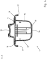
- FIG. 2 which shows a cross-sectional view in the area of the spring seat plate 8 with helical compression spring 12, it can be clearly seen that the spring link 1 is designed as a hollow profile in cross-section.
- the bead 10 is not shown.
- An opening 6 which is located at the top in relation to the vertical direction V is closed off by the spring seat plate 8.
- the hollow profile has a web 14 and legs 15 which extend laterally from the web 14 in the vertical direction V. Laterally projecting flanges 16 are arranged at the end of the legs 15 and, in turn, a collar 17 which is bent downwards in relation to the vertical direction is formed at the end of the flanges 16.
- the wall thickness W6 of the spring seat plate 8 is greater than the wall thickness W1 of the hollow profile.
- the helical compression spring 12 itself, with its final coil 13, is arranged such that it is positioned above the legs 15 relative to the vertical direction V. A force introduced into the spring link 1 by the helical compression spring 12 is thus introduced directly into the legs 15 via the spring seat plate 8.
- the largest distance A150 of the legs 15 preferably corresponds to 0.5 to 1.2 times, in particular 0.8 to 1.1 times the diameter D12 of the helical compression spring 12 or a receiving diameter AD12.
- the invention thus also relates to an arrangement on a motor vehicle axle with a Helical compression spring 12 and a spring link 1.
- a receiving diameter AD12 is preferably formed on the spring seat plate 8. This receiving diameter AD12 is suitable, in particular, for receiving the last coil 13 of the helical compression spring 12 accordingly.
- the legs are arranged in a V-shape to one another, so that a lower distance A15U is obtained in the vertical direction and increases in the direction of the opening 6 to the upper distance A15O.
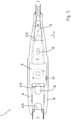
- the distance A15 between the legs 15 in the area of the spring seat plate 8 essentially corresponds to the distance A15 between the legs 15 in the area of the end 3.
- the distance A15 in the area of the spring seat plate 8 is a maximum of 1.2 times greater than the distance A15 between the legs 15 in the area of the end 3.
- the distance A15 between the legs 15 decreases, so that the spring link 1 is trapezoidal in section in its longitudinal direction 7, or the legs 15 are oriented so that they run towards one another.
- recesses 18 are provided to reduce weight and/or to prevent splash water from accumulating inside the hollow profile, which would promote corrosion due to standing water.
- a reinforcement plate 19 with additional stiffening is provided.
- This can also be clearly seen in the cross-sectional view according to Figure 4 .
- the collar 17, which is bent downwards in relation to the vertical direction is only formed in the area of the spring seat plate 8 for additional stiffening.
- the flange 16 is, according to the plan view of Figure 5 in the area of the spring seat plate 8, so that a thermal joining seam 20 can be produced, as indicated, for example.
- the spring link is shown again in a sectional view along the section line AA of Figure 3 in Figure 4 shown.
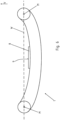
- FIG. 6 shows an alternative embodiment of a spring link 1 according to the invention.
- an effective line W is represented by the connection points 4, 5.
- This line runs through the respective centers M of the connection points. 4, 5.
- the spring link 1 now has a downwardly oriented arcuate profile in the vertical direction V. This ensures that the spring support surface 9 lies below the effective line W.
Landscapes
- Engineering & Computer Science (AREA)
- Mechanical Engineering (AREA)
- Springs (AREA)
- Vehicle Body Suspensions (AREA)
Description
- Die vorliegende Erfindung betrifft eine Achsanordnung für einen Federlenker für ein Kraftfahrzeug gemäß den Merkmalen im Oberbegriff von Patentanspruch 1.
- Aus dem Stand der Technik sind einzelne Radaufhängungen von Kraftfahrzeugen bekannt. Hierzu gibt es Mehrlenkerachsen, bei denen Lenker an einem Ende drehbar bzw. schwenkbar an einer Kraftfahrzeugkarosserie gekoppelt sind und mit dem gegenüberliegenden Ende des Lenkers drehbar bzw. schwenkbar an einem Radträger gekoppelt sind.
- Ein zumeist unterer Lenker einer Kraftfahrzeugachse weist zudem eine Aufnahme für eine Feder auf und optional weiterhin eine Aufnahme für einen Dämpfer und/oder Kraftfahrzeugstabilisator. Somit werden die beim Ein- oder Ausfedern des Kraftfahrzeugrades entstehenden Kräfte über die Feder aufgenommen.
- Ein entsprechender Federlenker ist dabei jedoch zumeist ein längliches schmales Bauteil. Eine Feder ist hingegen als Schraubendruckfeder ausgebildet und weist einen größeren Durchmesser auf als die Breite des Federlenkers selber. Federlenker sind daher zumeist im Bereich der Federaufnahme verbreitert ausgebildet. Dies führt jedoch beim Ein- oder Ausfedern dazu, dass in den Federlenker derart Kräfte eingeleitet werden, dass sich der Federlenker minimal aufweitet oder kontrahiert. Dieser Effekt wird auch als Atmen bezeichnet.
- Der Federlenker selbst steht dabei im Zielkonflikt, besonders biegesteif ausgebildet zu sein, jedoch gleichzeitig ein geringes Bauteilgewicht aufzuweisen, so dass gerade auf Seiten der ungefederten Radmassen ein geringes Gewicht vorhanden ist, so dass eine hohe Fahrdynamik des Kraftfahrzeuges ermöglicht wird.
- Aus der
DE 10 2012 100 719 A1 oder auch aus derDE 10 2013 222 234 A1 sind Federlenker bekannt, die als umgeformte Stahlblechbauteile hergestellt sind. Diese sind jedoch auch in ihrem Querschnitt im Bereich der Federaufnahme verbreitert ausgebildet. - Aus der
US 2015/115561 A1 ist ein Federlenker entsprechend des Oberbegriffs des Anspruchs 1 bekannt, bei dem auf ein offenes aufgeweitetes Hohlprofil ein Federsitzblech angeordnet wird. - Ferner ist aus der
DE 10 2011 053 927 A1 ein Federlenker bekannt, der als stranggepresstes Bauteil hergestellt ist. - Die
CN 204 172 635 U offenbart ebenfalls einen Federlenker, der Teil einer Fahrzeugaufhängung ist. - Aufgabe der vorliegenden Erfindung ist es daher, ausgehend vom Stand der Technik einen Federlenker aufzuzeigen, der als Stahlbauteil hergestellt ist und ein geringes Eigengewicht und eine gleichzeitig hohe Steifigkeit aufweist.
- Die zuvor genannte Aufgabe wird mit einer Anordnung für einen Federlenker gemäß den Merkmalen im Patentanspruch 1 gelöst.
- Der Federlenker für ein Kraftfahrzeug ist als längliches umgeformtes, im Querschnitt offenes Hohlprofil, aus einem Stahlwerkstoff hergestellt und weist an seinen Enden jeweils Anbindungspunkte auf. Insbesondere ist der Federlenker als Blechumformbauteil aus einer Stahlblechplatine hergestellt. Er zeichnet sich dadurch aus, dass der Federlenker in Einbaulage mit seiner Öffnung des Hohlprofils nach oben zeigend angeordnet ist, wobei auf oder in der Öffnung ein Federsitzblech zur Aufnahme einer Schraubendruckfeder mit dem Federlenker gekoppelt ist. Die Erfindung betrifft somit eine Achsanordnung, in welcher der erfindungsgemäße Federlenker eingegliedert ist.
- Erfindungsgemäß ist der Federlenker selbst somit als offenes bzw. teiloffenes Hohlprofil ausgebildet. Insbesondere weist dies im Querschnitt einen U-förmigen, C-förmigen bzw. hutförmigen Verlauf auf. Die Öffnung des Hohlprofils zeigt in Einbaulage des Federlenkers auf die Vertikalrichtung bezogen nach oben.
- Erfindungsgemäß ist nunmehr ein Federsitzblech auf der Öffnung bzw. teilweise in der Öffnung angeordnet und mit dem Federlenker gekoppelt. Diese Koppelung kann beispielsweise durch ein thermisches Fügeverfahren, beispielsweise Schweißen erfolgen. Der Federlenker selbst kann auch als zumindest partiell, insbesondere vollständig vergütetes Bauteil hergestellt sein. Der Federlenker kann auch mittels Warmumformen und Presshärten hergestellt sein.
- Die Feder ist insbesondere als Schraubendruckfeder ausgebildet, wobei ein Teil der Schraubendruckfeder mit seiner Windung, insbesondere mit seiner abschließenden Windung auf einer Federauflagenfläche des Federsitzbleches aufliegt. Die abschließende Windung der Schraubendruckfeder, mithin die gesamte Schraubendruckfeder ist somit oberhalb des Federlenkers angeordnet. Aufgrund der oberseitigen Anordnung ist es nicht notwendig, dass der Federlenker aufgeweitet ist. Das Querschnittsprofil zeichnet sich somit dadurch aus, dass es über den Verlauf mithin in Längsrichtung annähernd gleich ist bzw. sich verjüngt oder verringert. Nicht hingegen jedoch ist der Querschnitt aufgeweitet. Der Effekt des Atmens wird somit insbesondere vermieden, so dass der Kraftfluss innerhalb des Federlenkers verbessert ist.
- Insbesondere ist der Federlenker im Querschnitt derart aufgebaut, dass er einen Steg und von dem Steg abstehende Schenkel aufweist. Der Steg erstreckt sich in Einbaulage insbesondere in Horizontalrichtung orientiert und die Schenkel in Vertikalrichtung orientiert. Der Abstand der Schenkel zueinander ist erfindungsgemäß im Bereich des Federsitzbleches gleich oder kleiner gegenüber dem 1,2-fachen des Abstandes der Schenkel zueinander im Bereich eines Endes oder eines Anbindungspunktes. In bevorzugter Ausführungsvariante ist der Abstand der Schenkel zueinander im Bereich des Federsitzbleches kleiner gleich dem Abstand der Schenkel im Bereich des Endes oder des Anbindungspunktes. Somit ist der Federlenker im Bereich des Federsitzes insbesondere nicht aufgeweitet. Auch kann der Abstand der Schenkel zueinander relativ bezogen sein auf den Durchmesser der Schraubendruckfeder oder einen Aufnahmedurchmesser. Im Falle des Aufnahmedurchmessers ist dieser entsprechend ein Durchmesser zur Aufnahme der Schaubendruckfeder auf dem Federsitzblech. Insbesondere wird die letzte Windung der Schraubendruckfeder durch den Aufnahmedurchmesser auf dem Federsitzblech aufgenommen.
- In diesen Fällen entspricht insbesondere der Abstand der Schenkel zueinander im Bereich des Federsitzbleches, insbesondere der größte auftretende Abstand der Schenkel zueinander im Bereich des Federsitzbleches dem 0,5-fachen bis 1,2-fachen, insbesondere dem 0,8-fachen bis 1,1-fachen des Durchmessers der Schraubendruckfeder oder des Aufnahmedurchmessers.
- Die Schenkel selbst müssen dabei nicht vollständig in Vertikalrichtung verlaufen, sondern können auch schräg in einem spitzen Winkel zur Vertikalrichtung verlaufend angeordnet sein. Insbesondere vergrößert sich der Abstand der Schenkel in Richtung zu der Öffnung des Hohlprofils hin. Somit sind die Schenkel insbesondere V-förmig zueinander verlaufend angeordnet.
- Weiterhin weist besonders bevorzugt das Hohlprofil im Bereich des Federsitzbleches seitlich abstehende Flansche auf. Hierdurch vergrößert sich die Auflagenfläche und/oder Koppelungsfläche von Hohlprofil und Federsitzblech.
- Weiterhin bevorzugt sind insbesondere an den Schenkeln oder Flanschen Kragen ausgebildet. Die Kragen sind bevorzugt auf die Vertikalrichtung bezogen nach unten abgebogen. Hierdurch wird nochmals die Steifigkeit, insbesondere der Widerstand gegen Durchbiegung in Vertikalrichtung des erfindungsgemäßen Federlenkers erhöht.
- Weiterhin besonders bevorzugt ist das Hohlprofil in seiner Längsrichtung zumindest längenabschnittsweise trapezförmig aufeinander zu laufend ausgebildet. Insbesondere zu einem Ende hin verjüngt sich das Hohlprofil, somit wird der Abstand der Schenkel zueinander verringert.
- Die Anbindungspunkte sind als Lageraugen zur Aufnahme von Gummimetalllagern ausgebildet.
- Weiterhin bevorzugt bildet eine Verbindungsgerade durch die Anbindungspunkte, insbesondere durch den Mittelpunkt der Anbindungspunkte eine Wirklinie. Das Hohlprofil weist bezogen auf die Wirklinie einen bogenförmigen Verlauf auf. Insbesondere ist der bogenförmige Verlauf in Einbaulage in Richtung unterhalb der Wirklinie orientiert. Ferner wird der bogenförmige Verlauf bevorzugt derart ausgebildet, dass das Federsitzblech mit einer Federauflagenfläche unterhalb der Wirklinie liegt. Auch hierdurch kann der Kraftfluss innerhalb des Federlenkers optimiert werden, so dass insbesondere die einwirkenden Kräfte beim Einfederungsvorgang besser in die Anbindungspunkte geleitet werden und der vorbeschriebene Atmungseffekt verringert wird.
- Zur Herstellung des Federlenkers wird insbesondere eine Stahlblechplatine umgeformt und/oder abgekantet oder in anderer Weise formgebend bearbeitet. Verschiedene Maßnahmen zum Korrosionsschutz sind ebenfalls Bestandteil der Erfindung. Beispielsweise kann eine vorbeschichtete Platine bearbeitet werden. Der hergestellte Federlenker kann jedoch auch im KTL-Verfahren beschichtet werden.
- Insbesondere werden Blechstärken von 1,8 mm bis 4,75 mm verarbeitet, wobei eine Wandstärke des Federsitzbleches größer gleich, insbesondere größer der Wandstärke des Hohlprofils selber ist. Somit kann beispielsweise das Hohlprofil aus einer Wandstärke von 1,8 mm Blech ausgebildet sein und das Federsitzblech aus einer Wandstärke von 2,3 mm.
- Das Federsitzblech selber muss aus einem dickeren und somit gegen Biegung widerstandsfähigeren Blech ausgebildet sein. Das Hohlprofil selber kann aufgrund seiner geometrischen Form bereits eine hohes Widerstandsmoment gegen Durchbiegung in Einbaulage, gerade bezogen auf die Vertikalrichtung besitzen. Insgesamt kann somit ein Federlenker bereitgestellt werden, der ein geringes Bauteilgewicht bei gleichzeitig hohem Widerstandsmoment gegen Biegung aufweist.
- Weiterhin ist in und/oder auf der Öffnung des Hohlprofils zumindest längenabschnittsweise in Längsrichtung des Federlenkers ein Verstärkungsblech gekoppelt. Bevorzugt sind mehrere Verstärkungsbleche in dem Federlenker angeordnet. Somit kann je nach Steifigkeitsanforderung der Federlenker optimiert werden.
- Weiterhin besonders bevorzugt weist das Federsitzblech eine auf die Einbaulage bezogen gegenüber einer Federauflagenfläche nach oben orientierte Wulst auf, so dass die Wulst innenseitig in die Schraubendruckfeder und hier insbesondere in die Windung eingreift. Ein horizontales Abrutschen der Schraubendruckfeder wird durch die Wulst vermieden. Insbesondere liegt weiterhin die Windung teilweise auf die Vertikalrichtung bezogen einer vertikalen Kraftlinie direkt über den Schenkeln. Die insbesondere beim Einfederungsvorgang entstehenden Federkräfte können somit direkt in einen optimierten Kraftfluss innerhalb des Federlenkers abgeleitet werden.
- Weitere Vorteile, Merkmale, Eigenschaften und Aspekte der vorliegenden Erfindung sind Gegenstand der nachfolgenden Beschreibung. Bevorzugte Ausführungsvarianten werden in den schematischen Figuren dargestellt. Diese dienen dem einfachen Verständnis der Erfindung. Es zeigen:
- Figur 1
- den erfindungsgemäßen Federlenker in perspektivischer Ansicht,
- Figur 2
- eine schematische Querschnittsansicht mit Schraubendruckfeder im Bereich des Federsitzbleches,
- Figur 3
- eine Seitenansicht des Federlenkers,
- Figur 4
- eine Schnittlinie A-A aus
Figur 3 , - Figur 5
- eine Draufsicht auf den erfindungsgemäßen Federlenker und
- Figur 6
- eine schematische Ansicht eines nach unten gebogenen Federlenkers.
- In den Figuren werden für gleiche oder ähnliche Bauteile dieselben Bezugszeichen verwendet, auch wenn eine wiederholte Beschreibung aus Vereinfachungsgründen entfällt.
-
Figur 1 zeigt den erfindungsgemäßen Federlenker 1 in perspektivischer Ansicht. Dieser ist als längliches Blechumformbauteil ausgebildet und weist an seinen jeweiligen Enden 2, 3 Anbindungspunkte 4, 5 auf, so dass er an einem Ende 3 an einer nicht näher dargestellten Karosserie drehbar befestigt werden kann und am gegenüberliegendem Ende 2 an einem nicht näher dargestellten Radträger oder andersartigem Achsbauteil. Auch kann der Federlenker 1 an einem Achshilfsrahmen befestigt werden. Hierzu werden Gummimetalllager verwendet. Diese sind jedoch aus Vereinfachungsgründen nicht näher dargestellt. - Erfindungsgemäß ist der Federlenker 1 im Querschnitt als offenes Hohlprofil ausgebildet und weist eine Öffnung 6 auf, wobei die Öffnung 6 auf die Vertikalrichtung V bezogen in Einbaulage nach oben zeigt. In Längsrichtung 7 des Federlenkers 1 ist auf der Öffnung 6 ein Federsitzblech 8 abschnittsweise angeordnet. Das Federsitzblech 8 weist eine Federauflagefläche 9 auf sowie eine sich auf die Vertikalrichtung V bezogen nach oben erstreckende Wulst 10. Ferner ist eine Aufnahme 11 zur Koppelung eines nicht näher dargestellten Dämpfers vorgesehen.
- Gemäß
Figur 2 , welche eine Querschnittsansicht im Bereich des Federsitzbleches 8 mit Schraubendruckfeder 12 darstellt, ist gut zu erkennen, dass der Federlenker 1 im Querschnitt als Hohlprofil ausgebildet ist. Die Wulst 10 ist nicht dargestellt. Eine auf die Vertikalrichtung V bezogen obenliegende Öffnung 6 ist von dem Federsitzblech 8 abgeschlossen. Das Hohlprofil weist einen Steg 14 sowie sich seitlich von dem Steg 14 in Vertikalrichtung V orientiert erstreckende Schenkel 15 auf. Am Ende der Schenkel 15 sind seitlich abstehende Flansche 16 angeordnet und wiederum am Ende der Flansche 16 ist jeweils ein auf die Vertikalrichtung bezogen nach unten abgebogener Kragen 17 ausgebildet. - Die Wandstärke W6 des Federsitzbleches 8 ist größer als die Wandstärke W1 des Hohlprofils. Die Schraubendruckfeder 12 selber ist mit ihrer abschließenden Windung 13 derart angeordnet, dass diese auf die Vertikalrichtung V bezogen oberhalb der Schenkel 15 angeordnet ist. Eine durch die Schraubendruckfeder 12 in den Federlenker 1 eingeleitete Kraft wird somit über das Federsitzblech 8 direkt in die Schenkel 15 eingeleitet.
- Der größte Abstand A15O der Schenkel 15 entspricht dabei bevorzugt dem 0,5- bis 1,2-fachen, insbesondere 0,8- bis 1,1-fachen Durchmesser D12 der Schraubendruckfeder 12 oder eines Aufnahmedurchmessers AD12. Die Erfindung betrifft somit auch eine Anordnung an einer Kraftfahrzeugachse mit einer Schraubendruckfeder 12 und einem Federlenker 1. Es ist bevorzugt ein Aufnahmedurchmesser AD12 an dem Federsitzblech 8 ausgebildet. Dieser Aufnahmedurchmesser AD12 ist dazu geeignet insbesondere die letzte Windung 13 der Schraubendruckfeder 12 entsprechend aufzunehmen.
- Ferner ist zu erkennen, dass die Schenkel V-förmig zueinander angeordnet sind, so dass sich auf die Vertikalrichtung bezogen ein unterer Abstand A15U ergibt und sich in Richtung zur Öffnung 6 hin vergrößert zum oberen Abstand A15O.
- Gut zu erkennen ist in der Draufsicht gemäß
Figur 5 , dass der Abstand A15 der Schenkel 15 im Bereich des Federsitzbleches 8 im Wesentlichen dem Abstand A15 der Schenkel 15 im Bereich des Endes 3 entspricht. Der Abstand A15 ist im Bereich des Federsitzbleches 8 maximal 1,2-fach größer als der Abstand A15 der Schenkel 15 im Bereich des Endes 3. Zu dem anderen Ende 2 hin verringert sich der Abstand A15 der Schenkel 15 zueinander, so dass der Federlenker 1 in seiner Längsrichtung 7 abschnittsweise trapezförmig ausgebildet ist bzw. die Schenkel 15 aufeinander zu laufend orientiert sind. Ferner sind Aussparungen 18 vorgesehen zur Gewichtsreduzierung und/oder damit Spritzwasser sich nicht im Inneren des Hohlprofils staut, so dass hierdurch Korrosion aufgrund stehenden Wassers begünstigt würde. - Ferner ist ein Verstärkungsblech 19 mit zusätzlicher Versteifung vorgesehen. Dies ist auch nochmals gut zu erkennen in der Querschnittsansicht gemäß
Figur 4 . Gemäß der Seitenansicht vonFigur 3 ist nochmal zu erkennen, dass der auf die Vertikalrichtung bezogen nach unten abgebogene Kragen 17 nur im Bereich des Federsitzbleches 8 zur zusätzlichen Aussteifung gebildet ist. Ferner ist der Flansch 16 gemäß Draufsicht vonFigur 5 im Bereich des Federsitzbleches 8 verbreitert, so dass eine beispielsweise angedeutete thermische Fügenaht 20 hergestellt werden kann. Nochmals ist der Federlenker in einer Schnittansicht gemäß der Schnittlinie A-A vonFigur 3 inFigur 4 dargestellt. -
Figur 6 zeigt einen erfindungsgemäßen Federlenker 1 in alternativer Ausgestaltungsvariante. Hierbei ist durch die Anbindungspunkte 4, 5 eine Wirklinie W dargestellt. Diese verläuft durch die jeweiligen Mittelpunkte M der Anbindungspunkte 4, 5. Nunmehr weist der Federlenker 1 auf die Vertikalrichtung V einen nach unten orientierten bogenförmigen Verlauf auf. Hierdurch wird erreicht, dass die Federauflagenfläche 9 unterhalb der Wirklinie W liegt. -
- 1 -
- Federlenker
- 2 -
- Ende zu 1
- 3 -
- Ende zu 1
- 4 -
- Anbindungspunkt zu 2
- 5 -
- Anbindungspunkt zu 3
- 6 -
- Öffnung
- 7 -
- Längsrichtung zu 1
- 8 -
- Federsitzblech
- 9 -
- Federauflagefläche zu 8
- 10 -
- Wulst
- 11 -
- Aufnahme
- 12 -
- Schraubendruckfeder
- 13 -
- Windung zu 12
- 14 -
- Steg
- 15 -
- Schenkel
- 16 -
- Flansch
- 17 -
- Kragen
- 18 -
- Aussparung
- 19 -
- Verstärkungsblech
- 20 -
- thermische Fügenaht
- A15 -
- Abstand zu 15
- A15O -
- Abstand oben
- A15U -
- Abstand unten
- AD12 -
- Aufnahmedurchmesser
- D12 -
- Durchmesser
- M -
- Mittelpunkt
- V -
- Vertikalrichtung
- W -
- Wirklinie
Claims (10)
- Achsanordnung für ein Kraftfahrzeug, aufweisend einen Federlenker (1) und ein Federsitzblech (8), wobei der Federlenker (1) als längliches umgeformtes im Querschnitt offenes U-förmig oder C-förmig oder hutförmig ausgebildet Hohlprofil mit zwei gegenüberliegenden Schenkeln (15) aus einem Stahlwerkstoff hergestellt ist und an seinen Enden (2, 3) jeweils Anbindungspunkte (4, 5) aufweist, wobei der Federlenker (1) in Einbaulage mit seiner Öffnung (6) des Hohlprofils nach oben zeigend angeordnet ist, wobei auf und/oder teilweise in der Öffnung (6) das Federsitzblech (8) zur Aufnahme einer Schraubendruckfeder (12) mit dem Federlenker (1) gekoppelt ist, wobei in und/oder auf der Öffnung (6) des Hohlprofils zumindest längenabschnittsweise in Längsrichtung des Federlenkers (1) ein Verstärkungsblech (19) gekoppelt ist, wobei ein Abstand (A15) der Schenkel (15) zueinander im Bereich des Federsitzbleches (8) gleich oder kleiner ist gegenüber einem 1,2-fachen Abstand (A15) der Schenkel (15) zueinander im Bereich eines Endes (2, 3) oder eines Anbindungspunktes (4, 5), dadurch gekennzeichnet, dass die Anbindungspunkte (4, 5) als Lageraugen ausgebildet sind und in den Lageraugen Gummimetalllager angeordnet sind.
- Achsanordnung nach Anspruch 1, dadurch gekennzeichnet, dass der Abstand (A15) der Schenkel (15) im Bereich des Federsitzbleches (8) kleiner gleich dem Abstand (A15) der Schenkel (15) im Bereich des Endes (2, 3) oder des Anbindungspunktes (4, 5) ist.
- Achsanordnung nach Anspruch 2, dadurch gekennzeichnet, dass ein Abstand (A15) der Schenkel (15) zueinander im Bereich des Federsitzbleches (8) einem 0,5-fachen bis 1,2-fachen, bevorzugt 0,8-fachen bis 1,1-fachen Aufnahmedurchmesser (AD12) auf dem Federsitzblech (8) entspricht, wobei der Aufnahmedurchmesser (AD12) geeignet ist, eine Schraubendruckfeder (12) aufzunehmen.
- Achsanordnung nach einem der Ansprüche 1 bis 3, dadurch gekennzeichnet, dass sich der Abstand (A15) der Schenkel (15) in Richtung zu der Öffnung (6) hin vergrößert, insbesondere sind die Schenkel (15) in einem Winkel zu einander verlaufend orientiert angeordnet.
- Achsanordnung nach einem der Ansprüche 1 bis 4, dadurch gekennzeichnet, dass das Hohlprofil im Bereich des Federsitzbleches (8) seitlich abstehende Flansche (16) und/oder Kragen (17) aufweist.
- Achsanordnung nach einem der Ansprüche 1 bis 5, dadurch gekennzeichnet, dass das Hohlprofil in seiner Längsrichtung (7) zumindest längenabschnittsweise trapezförmig aufeinander zulaufend ausgebildet ist, insbesondere zu einem Ende (2) hin.
- Achsanordnung nach einem der Ansprüche 1 bis 6, dadurch gekennzeichnet, dass eine Verbindungsgerade durch die Anbindungspunkte (4, 5) eine Wirklinie (W) bildet, wobei das Hohlprofil bezogen auf die Wirklinie (W) einen bogenförmigen Verlauf aufweist.
- Achsanordnung nach Anspruch 7, dadurch gekennzeichnet, dass der bogenförmige Verlauf unterhalb der Wirklinie orientiert ist und/oder dass das Federsitzblech (8) eine Federauflagefläche (9) aufweist, die unterhalb der Wirklinie liegt.
- Achsanordnung nach einem der Ansprüche 1 bis 8, dadurch gekennzeichnet, dass eine Wandstärke des Hohlprofils von 1,8 mm bis 4,75 mm ausgebildet ist und eine Wandstärke (W8) des Federsitzbleches (8) größer gleich der Wandstärke (W1) des Hohlprofils ausgebildet ist.
- Achsanordnung nach einem der Ansprüche 1 bis 9, dadurch gekennzeichnet, dass das Federsitzblech (8) eine auf die Einbaulage bezogen gegenüber einer Federauflagefläche (9) nach oben orientierte Wulst (10) aufweist, so dass die Wulst (10) innenseitig in die Schraubendruckfeder (12) eingreift.
Applications Claiming Priority (1)
| Application Number | Priority Date | Filing Date | Title |
|---|---|---|---|
| DE102016100666.1A DE102016100666A1 (de) | 2016-01-15 | 2016-01-15 | Federlenker aus Stahl |
Publications (2)
| Publication Number | Publication Date |
|---|---|
| EP3192680A1 EP3192680A1 (de) | 2017-07-19 |
| EP3192680B1 true EP3192680B1 (de) | 2025-03-19 |
Family
ID=57681362
Family Applications (1)
| Application Number | Title | Priority Date | Filing Date |
|---|---|---|---|
| EP16205830.9A Active EP3192680B1 (de) | 2016-01-15 | 2016-12-21 | Achsanordnung für ein kraftfahrzeug |
Country Status (4)
| Country | Link |
|---|---|
| US (1) | US10343473B2 (de) |
| EP (1) | EP3192680B1 (de) |
| CN (1) | CN106976369B (de) |
| DE (1) | DE102016100666A1 (de) |
Families Citing this family (13)
| Publication number | Priority date | Publication date | Assignee | Title |
|---|---|---|---|---|
| DE102016123499B4 (de) * | 2016-12-05 | 2024-07-25 | Benteler Automobiltechnik Gmbh | Radlenker für eine Radaufhängung in einem Fahrzeug |
| DE102018216186B3 (de) | 2018-09-21 | 2019-06-27 | Audi Ag | Schmaler Federlenker für die Radaufhängung an einem Kraftfahrzeug |
| KR102074731B1 (ko) * | 2018-10-11 | 2020-02-07 | 주식회사 포스코 | 스프링 링크 |
| DE102018218082A1 (de) | 2018-10-23 | 2020-04-23 | Volkswagen Aktiengesellschaft | Federlenker in Blechkonstruktion |
| EP3904131B1 (de) * | 2018-12-26 | 2023-08-16 | Nippon Steel Corporation | Bauteil einer kraftfahrzeugaufhängung |
| DE102019102493A1 (de) * | 2019-01-31 | 2020-08-06 | Benteler Automobiltechnik Gmbh | Kraftfahrzeuglenker |
| DE102019108548B4 (de) * | 2019-04-02 | 2023-12-28 | Benteler Automobiltechnik Gmbh | Federlenker |
| DE102019109177A1 (de) * | 2019-04-08 | 2020-10-08 | Man Truck & Bus Se | Achslenker für eine Radaufhängung |
| EP3722121B1 (de) * | 2019-04-11 | 2021-11-24 | Autotech Engineering Deutschland GmbH | Einschaliger federlenker |
| DE102019129431A1 (de) * | 2019-10-31 | 2021-05-06 | Thk Co., Ltd. | Fahrwerkslenker |
| US20220088986A1 (en) * | 2019-11-19 | 2022-03-24 | John Dinkel | Friction Free Roller Spring Perch |
| ES3032497T3 (en) | 2022-10-31 | 2025-07-21 | Benteler Automobiltechnik Gmbh | Spring link |
| US12328207B2 (en) | 2023-01-18 | 2025-06-10 | Samsung Electronics Co., Ltd. | Iterative channel estimation for new radio (NR) |
Citations (11)
| Publication number | Priority date | Publication date | Assignee | Title |
|---|---|---|---|---|
| JPH11241745A (ja) * | 1998-02-25 | 1999-09-07 | Tokai Rubber Ind Ltd | ブッシュ装着用部材 |
| JP2002316228A (ja) * | 2001-04-18 | 2002-10-29 | F Tech:Kk | 車両用サスペンションアームの製造方法 |
| DE102008047015A1 (de) * | 2007-09-14 | 2009-07-09 | Hyundai Mobis Co., Ltd. | Verfahren zum Herstellen eines Lenkerarms unter Verwendung eines Strangpressprozesses mit variabler Krümmung und damit hergestellter Lenkerarm des Doppelhohlraumtyps |
| KR20100001309A (ko) * | 2008-06-26 | 2010-01-06 | 현대제철 주식회사 | 차량용 후륜현가장치의 어시스트 아암 및 그 제조방법 |
| DE102010051741A1 (de) * | 2010-11-19 | 2012-05-24 | Benteler Automobiltechnik Gmbh | Verfahren zur Herstellung eines Lenkerarms und Lenkerarm |
| CN203460637U (zh) * | 2013-07-30 | 2014-03-05 | 上海汇众汽车制造有限公司 | 多连杆后悬架下控制臂 |
| CN104309427A (zh) * | 2014-09-29 | 2015-01-28 | 上汽通用五菱汽车股份有限公司 | 一种汽车悬架摆臂结构 |
| CN204172635U (zh) * | 2014-09-29 | 2015-02-25 | 上汽通用五菱汽车股份有限公司 | 一种汽车悬架摆臂结构 |
| CN204567182U (zh) * | 2015-01-22 | 2015-08-19 | 安徽机电职业技术学院 | 一种下控制臂结构 |
| CN105235462A (zh) * | 2015-10-26 | 2016-01-13 | 上汽通用五菱汽车股份有限公司 | 一种悬架控制臂 |
| CN205498528U (zh) * | 2016-01-20 | 2016-08-24 | 山东新大洋电动车有限公司 | 一种集成弹簧座的轻量化后拖曳臂总成 |
Family Cites Families (21)
| Publication number | Priority date | Publication date | Assignee | Title |
|---|---|---|---|---|
| US3797852A (en) * | 1972-08-07 | 1974-03-19 | Chrysler Corp | Suspension system |
| JP4569963B2 (ja) | 2003-07-03 | 2010-10-27 | アイシン軽金属株式会社 | サスペンションアーム |
| DE102004003151B4 (de) * | 2004-01-21 | 2019-01-17 | Volkswagen Ag | Federlenker für eine Radaufhängung eines Kraftfahrzeugs |
| JP4360227B2 (ja) * | 2004-02-19 | 2009-11-11 | マツダ株式会社 | サスペンション装置 |
| DE102006014730A1 (de) * | 2006-03-30 | 2007-10-04 | Volkswagen Ag | Einteiliger Federlenker |
| DE102006032595A1 (de) * | 2006-07-14 | 2008-01-17 | Volkswagen Ag | Federlenker für eine Radaufhängung eines Kraftfahrzeugs |
| US7959171B2 (en) * | 2007-11-26 | 2011-06-14 | Nissan Motor Co., Ltd. | Lower spring seat mounting structure for vehicle suspension |
| DE102008013182A1 (de) * | 2008-03-07 | 2009-09-17 | Benteler Automobiltechnik Gmbh | Lenkerbauteil |
| DE112010001366T5 (de) * | 2009-03-20 | 2012-10-11 | Magna International Inc. | Radaufhängungsarm/-strebe für ein Kraftfahrzeug und Verfahren zum Herstellen desselben/derselben |
| DE102009042403B4 (de) * | 2009-09-21 | 2023-01-12 | Volkswagen Ag | Federlenker für eine Radaufhängung eines Kraftfahrzeugs |
| DE102011000462A1 (de) * | 2011-02-02 | 2012-08-16 | Gmf Umformtechnik Gmbh | Einschaliger Federlenker |
| DE102011053927A1 (de) * | 2011-09-26 | 2013-03-28 | Dura Automotive Body & Glass Systems Gmbh | Federlenker |
| JP5877068B2 (ja) * | 2012-01-05 | 2016-03-02 | 本田技研工業株式会社 | スプリングシート |
| DE102012100719A1 (de) | 2012-01-30 | 2013-08-01 | Gmf Umformtechnik Gmbh | Einschaliger Federlenker |
| CN104114384A (zh) * | 2012-02-21 | 2014-10-22 | 株式会社万 | 车辆用悬挂臂 |
| DE102012104909A1 (de) * | 2012-06-06 | 2013-12-12 | Benteler Automobiltechnik Gmbh | Querlenker sowie Verfahren zum Herstellen des Querlenkers |
| DE102013205686A1 (de) * | 2013-03-28 | 2014-10-02 | Ford Global Technologies, Llc | Verbundlenkerachse für Fahrzeuge |
| CN203511209U (zh) * | 2013-09-03 | 2014-04-02 | 上海通用汽车有限公司 | 一种汽车后下控制臂及汽车后下控制臂装置 |
| DE102013222234B4 (de) | 2013-10-31 | 2024-04-18 | Volkswagen Aktiengesellschaft | Federlenker für eine Kraftfahrzeugradaufhängung |
| DE102014118518B4 (de) * | 2014-12-12 | 2022-03-24 | Benteler Automobiltechnik Gmbh | Mehrteiliger Federlenker |
| CN104626909A (zh) * | 2015-02-02 | 2015-05-20 | 成都科力夫科技有限公司 | 一种减震弹簧的连接方法 |
-
2016
- 2016-01-15 DE DE102016100666.1A patent/DE102016100666A1/de active Granted
- 2016-12-21 EP EP16205830.9A patent/EP3192680B1/de active Active
-
2017
- 2017-01-13 CN CN201710023129.8A patent/CN106976369B/zh active Active
- 2017-01-13 US US15/406,621 patent/US10343473B2/en active Active
Patent Citations (11)
| Publication number | Priority date | Publication date | Assignee | Title |
|---|---|---|---|---|
| JPH11241745A (ja) * | 1998-02-25 | 1999-09-07 | Tokai Rubber Ind Ltd | ブッシュ装着用部材 |
| JP2002316228A (ja) * | 2001-04-18 | 2002-10-29 | F Tech:Kk | 車両用サスペンションアームの製造方法 |
| DE102008047015A1 (de) * | 2007-09-14 | 2009-07-09 | Hyundai Mobis Co., Ltd. | Verfahren zum Herstellen eines Lenkerarms unter Verwendung eines Strangpressprozesses mit variabler Krümmung und damit hergestellter Lenkerarm des Doppelhohlraumtyps |
| KR20100001309A (ko) * | 2008-06-26 | 2010-01-06 | 현대제철 주식회사 | 차량용 후륜현가장치의 어시스트 아암 및 그 제조방법 |
| DE102010051741A1 (de) * | 2010-11-19 | 2012-05-24 | Benteler Automobiltechnik Gmbh | Verfahren zur Herstellung eines Lenkerarms und Lenkerarm |
| CN203460637U (zh) * | 2013-07-30 | 2014-03-05 | 上海汇众汽车制造有限公司 | 多连杆后悬架下控制臂 |
| CN104309427A (zh) * | 2014-09-29 | 2015-01-28 | 上汽通用五菱汽车股份有限公司 | 一种汽车悬架摆臂结构 |
| CN204172635U (zh) * | 2014-09-29 | 2015-02-25 | 上汽通用五菱汽车股份有限公司 | 一种汽车悬架摆臂结构 |
| CN204567182U (zh) * | 2015-01-22 | 2015-08-19 | 安徽机电职业技术学院 | 一种下控制臂结构 |
| CN105235462A (zh) * | 2015-10-26 | 2016-01-13 | 上汽通用五菱汽车股份有限公司 | 一种悬架控制臂 |
| CN205498528U (zh) * | 2016-01-20 | 2016-08-24 | 山东新大洋电动车有限公司 | 一种集成弹簧座的轻量化后拖曳臂总成 |
Also Published As
| Publication number | Publication date |
|---|---|
| CN106976369A (zh) | 2017-07-25 |
| CN106976369B (zh) | 2022-07-26 |
| US10343473B2 (en) | 2019-07-09 |
| DE102016100666A1 (de) | 2017-07-20 |
| US20170203624A1 (en) | 2017-07-20 |
| EP3192680A1 (de) | 2017-07-19 |
Similar Documents
| Publication | Publication Date | Title |
|---|---|---|
| EP3192680A1 (de) | Federlenker aus stahl | |
| EP2809531B1 (de) | Einschaliger federlenker | |
| EP2670611B1 (de) | Einschaliger federlenker | |
| DE69615889T2 (de) | Aufhängungslenker | |
| DE69931983T2 (de) | Stabilisator | |
| DE102010036681A1 (de) | Lenkerarm eines Mehrlenkeraufhängungssystems eines Fahrzeuges | |
| DE102008013182A1 (de) | Lenkerbauteil | |
| DE202018104424U1 (de) | C-Säulen-Anordnung für Fahrzeugkarosserie | |
| DE102019108548B4 (de) | Federlenker | |
| EP2918430B1 (de) | Fahrwerkslenker für ein Kraftfahrzeug | |
| DE102014118518A1 (de) | Mehrteiliger Federlenker | |
| DE102013000362B4 (de) | Fahrerhauslagerung | |
| DE102004008957A1 (de) | Federlenker für eine Radaufhängung eines Kraftfahrzeugs | |
| EP2697083A1 (de) | Schwenklager | |
| DE102011015542A1 (de) | Schottstruktur, Wasserkasten und Vorderwagen für ein Kraftfahrzeug | |
| DE10110495B4 (de) | Achseinbindung für gefederte Fahrzeugachsen | |
| DE102004056884A1 (de) | Lager, insbesondere Gummi/Metall-Lager zur Anlenkung eines Stabilisators an einem Kraftfahrzeug | |
| DE102020129504A1 (de) | Fahrgestellkonstruktion für ein Nutzfahrzeug | |
| DE102013210142A1 (de) | Lenkereinheit | |
| DE102004009722A1 (de) | Radführungslenker | |
| DE102006032595A1 (de) | Federlenker für eine Radaufhängung eines Kraftfahrzeugs | |
| DE19846400B4 (de) | Verbundlenker-Hinterachse | |
| DE102016107048B4 (de) | Rahmeneinheit | |
| DE102009032919A1 (de) | Federungsanordnung mit einer Blattfeder aus einem Faserverbundwerkstoff | |
| EP3870463B1 (de) | Federlenker in blechkonstruktion |
Legal Events
| Date | Code | Title | Description |
|---|---|---|---|
| PUAI | Public reference made under article 153(3) epc to a published international application that has entered the european phase |
Free format text: ORIGINAL CODE: 0009012 |
|
| STAA | Information on the status of an ep patent application or granted ep patent |
Free format text: STATUS: REQUEST FOR EXAMINATION WAS MADE |
|
| 17P | Request for examination filed |
Effective date: 20170413 |
|
| AK | Designated contracting states |
Kind code of ref document: A1 Designated state(s): AL AT BE BG CH CY CZ DE DK EE ES FI FR GB GR HR HU IE IS IT LI LT LU LV MC MK MT NL NO PL PT RO RS SE SI SK SM TR |
|
| AX | Request for extension of the european patent |
Extension state: BA ME |
|
| STAA | Information on the status of an ep patent application or granted ep patent |
Free format text: STATUS: EXAMINATION IS IN PROGRESS |
|
| 17Q | First examination report despatched |
Effective date: 20180104 |
|
| GRAP | Despatch of communication of intention to grant a patent |
Free format text: ORIGINAL CODE: EPIDOSNIGR1 |
|
| STAA | Information on the status of an ep patent application or granted ep patent |
Free format text: STATUS: GRANT OF PATENT IS INTENDED |
|
| INTG | Intention to grant announced |
Effective date: 20241122 |
|
| GRAS | Grant fee paid |
Free format text: ORIGINAL CODE: EPIDOSNIGR3 |
|
| GRAA | (expected) grant |
Free format text: ORIGINAL CODE: 0009210 |
|
| STAA | Information on the status of an ep patent application or granted ep patent |
Free format text: STATUS: THE PATENT HAS BEEN GRANTED |
|
| AK | Designated contracting states |
Kind code of ref document: B1 Designated state(s): AL AT BE BG CH CY CZ DE DK EE ES FI FR GB GR HR HU IE IS IT LI LT LU LV MC MK MT NL NO PL PT RO RS SE SI SK SM TR |
|
| REG | Reference to a national code |
Ref country code: GB Ref legal event code: FG4D Free format text: NOT ENGLISH |
|
| REG | Reference to a national code |
Ref country code: CH Ref legal event code: EP |
|
| REG | Reference to a national code |
Ref country code: IE Ref legal event code: FG4D Free format text: LANGUAGE OF EP DOCUMENT: GERMAN |
|
| REG | Reference to a national code |
Ref country code: DE Ref legal event code: R096 Ref document number: 502016016915 Country of ref document: DE |
|
| PG25 | Lapsed in a contracting state [announced via postgrant information from national office to epo] |
Ref country code: RS Free format text: LAPSE BECAUSE OF FAILURE TO SUBMIT A TRANSLATION OF THE DESCRIPTION OR TO PAY THE FEE WITHIN THE PRESCRIBED TIME-LIMIT Effective date: 20250619 |
|
| PG25 | Lapsed in a contracting state [announced via postgrant information from national office to epo] |
Ref country code: FI Free format text: LAPSE BECAUSE OF FAILURE TO SUBMIT A TRANSLATION OF THE DESCRIPTION OR TO PAY THE FEE WITHIN THE PRESCRIBED TIME-LIMIT Effective date: 20250319 |
|
| REG | Reference to a national code |
Ref country code: LT Ref legal event code: MG9D |
|
| PG25 | Lapsed in a contracting state [announced via postgrant information from national office to epo] |
Ref country code: NO Free format text: LAPSE BECAUSE OF FAILURE TO SUBMIT A TRANSLATION OF THE DESCRIPTION OR TO PAY THE FEE WITHIN THE PRESCRIBED TIME-LIMIT Effective date: 20250619 |
|
| PG25 | Lapsed in a contracting state [announced via postgrant information from national office to epo] |
Ref country code: HR Free format text: LAPSE BECAUSE OF FAILURE TO SUBMIT A TRANSLATION OF THE DESCRIPTION OR TO PAY THE FEE WITHIN THE PRESCRIBED TIME-LIMIT Effective date: 20250319 |
|
| PG25 | Lapsed in a contracting state [announced via postgrant information from national office to epo] |
Ref country code: LV Free format text: LAPSE BECAUSE OF FAILURE TO SUBMIT A TRANSLATION OF THE DESCRIPTION OR TO PAY THE FEE WITHIN THE PRESCRIBED TIME-LIMIT Effective date: 20250319 |
|
| PG25 | Lapsed in a contracting state [announced via postgrant information from national office to epo] |
Ref country code: GR Free format text: LAPSE BECAUSE OF FAILURE TO SUBMIT A TRANSLATION OF THE DESCRIPTION OR TO PAY THE FEE WITHIN THE PRESCRIBED TIME-LIMIT Effective date: 20250620 Ref country code: BG Free format text: LAPSE BECAUSE OF FAILURE TO SUBMIT A TRANSLATION OF THE DESCRIPTION OR TO PAY THE FEE WITHIN THE PRESCRIBED TIME-LIMIT Effective date: 20250319 |
|
| REG | Reference to a national code |
Ref country code: NL Ref legal event code: MP Effective date: 20250319 |
|
| PG25 | Lapsed in a contracting state [announced via postgrant information from national office to epo] |
Ref country code: NL Free format text: LAPSE BECAUSE OF FAILURE TO SUBMIT A TRANSLATION OF THE DESCRIPTION OR TO PAY THE FEE WITHIN THE PRESCRIBED TIME-LIMIT Effective date: 20250319 |
|
| PG25 | Lapsed in a contracting state [announced via postgrant information from national office to epo] |
Ref country code: SE Free format text: LAPSE BECAUSE OF FAILURE TO SUBMIT A TRANSLATION OF THE DESCRIPTION OR TO PAY THE FEE WITHIN THE PRESCRIBED TIME-LIMIT Effective date: 20250319 |
|
| PG25 | Lapsed in a contracting state [announced via postgrant information from national office to epo] |
Ref country code: SM Free format text: LAPSE BECAUSE OF FAILURE TO SUBMIT A TRANSLATION OF THE DESCRIPTION OR TO PAY THE FEE WITHIN THE PRESCRIBED TIME-LIMIT Effective date: 20250319 |
|
| PG25 | Lapsed in a contracting state [announced via postgrant information from national office to epo] |
Ref country code: PT Free format text: LAPSE BECAUSE OF FAILURE TO SUBMIT A TRANSLATION OF THE DESCRIPTION OR TO PAY THE FEE WITHIN THE PRESCRIBED TIME-LIMIT Effective date: 20250721 Ref country code: ES Free format text: LAPSE BECAUSE OF FAILURE TO SUBMIT A TRANSLATION OF THE DESCRIPTION OR TO PAY THE FEE WITHIN THE PRESCRIBED TIME-LIMIT Effective date: 20250319 |
|
| PG25 | Lapsed in a contracting state [announced via postgrant information from national office to epo] |
Ref country code: PL Free format text: LAPSE BECAUSE OF FAILURE TO SUBMIT A TRANSLATION OF THE DESCRIPTION OR TO PAY THE FEE WITHIN THE PRESCRIBED TIME-LIMIT Effective date: 20250319 Ref country code: IT Free format text: LAPSE BECAUSE OF FAILURE TO SUBMIT A TRANSLATION OF THE DESCRIPTION OR TO PAY THE FEE WITHIN THE PRESCRIBED TIME-LIMIT Effective date: 20250319 |
|
| PG25 | Lapsed in a contracting state [announced via postgrant information from national office to epo] |
Ref country code: CZ Free format text: LAPSE BECAUSE OF FAILURE TO SUBMIT A TRANSLATION OF THE DESCRIPTION OR TO PAY THE FEE WITHIN THE PRESCRIBED TIME-LIMIT Effective date: 20250319 Ref country code: EE Free format text: LAPSE BECAUSE OF FAILURE TO SUBMIT A TRANSLATION OF THE DESCRIPTION OR TO PAY THE FEE WITHIN THE PRESCRIBED TIME-LIMIT Effective date: 20250319 |
|
| PG25 | Lapsed in a contracting state [announced via postgrant information from national office to epo] |
Ref country code: RO Free format text: LAPSE BECAUSE OF FAILURE TO SUBMIT A TRANSLATION OF THE DESCRIPTION OR TO PAY THE FEE WITHIN THE PRESCRIBED TIME-LIMIT Effective date: 20250319 |
|
| PG25 | Lapsed in a contracting state [announced via postgrant information from national office to epo] |
Ref country code: SK Free format text: LAPSE BECAUSE OF FAILURE TO SUBMIT A TRANSLATION OF THE DESCRIPTION OR TO PAY THE FEE WITHIN THE PRESCRIBED TIME-LIMIT Effective date: 20250319 |
|
| PG25 | Lapsed in a contracting state [announced via postgrant information from national office to epo] |
Ref country code: IS Free format text: LAPSE BECAUSE OF FAILURE TO SUBMIT A TRANSLATION OF THE DESCRIPTION OR TO PAY THE FEE WITHIN THE PRESCRIBED TIME-LIMIT Effective date: 20250719 |
|
| REG | Reference to a national code |
Ref country code: DE Ref legal event code: R097 Ref document number: 502016016915 Country of ref document: DE |
|
| PG25 | Lapsed in a contracting state [announced via postgrant information from national office to epo] |
Ref country code: DK Free format text: LAPSE BECAUSE OF FAILURE TO SUBMIT A TRANSLATION OF THE DESCRIPTION OR TO PAY THE FEE WITHIN THE PRESCRIBED TIME-LIMIT Effective date: 20250319 |
|
| PLBE | No opposition filed within time limit |
Free format text: ORIGINAL CODE: 0009261 |
|
| STAA | Information on the status of an ep patent application or granted ep patent |
Free format text: STATUS: NO OPPOSITION FILED WITHIN TIME LIMIT |
|
| REG | Reference to a national code |
Ref country code: CH Ref legal event code: L10 Free format text: ST27 STATUS EVENT CODE: U-0-0-L10-L00 (AS PROVIDED BY THE NATIONAL OFFICE) Effective date: 20260128 |
|
| 26N | No opposition filed |
Effective date: 20251222 |
|
| PGFP | Annual fee paid to national office [announced via postgrant information from national office to epo] |
Ref country code: DE Payment date: 20251219 Year of fee payment: 10 |