EP3192575B1 - Dreheinrichtungs-baugruppe für ein spielzeug - Google Patents
Dreheinrichtungs-baugruppe für ein spielzeug Download PDFInfo
- Publication number
- EP3192575B1 EP3192575B1 EP16203080.3A EP16203080A EP3192575B1 EP 3192575 B1 EP3192575 B1 EP 3192575B1 EP 16203080 A EP16203080 A EP 16203080A EP 3192575 B1 EP3192575 B1 EP 3192575B1
- Authority
- EP
- European Patent Office
- Prior art keywords
- hub part
- rotating device
- device module
- module according
- thread
- Prior art date
- Legal status (The legal status is an assumption and is not a legal conclusion. Google has not performed a legal analysis and makes no representation as to the accuracy of the status listed.)
- Active
Links
Images


Classifications
-
- A—HUMAN NECESSITIES
- A63—SPORTS; GAMES; AMUSEMENTS
- A63H—TOYS, e.g. TOPS, DOLLS, HOOPS OR BUILDING BLOCKS
- A63H17/00—Toy vehicles, e.g. with self-drive; ; Cranes, winches or the like; Accessories therefor
- A63H17/26—Details; Accessories
- A63H17/262—Chassis; Wheel mountings; Wheels; Axles; Suspensions; Fitting body portions to chassis
-
- A—HUMAN NECESSITIES
- A63—SPORTS; GAMES; AMUSEMENTS
- A63H—TOYS, e.g. TOPS, DOLLS, HOOPS OR BUILDING BLOCKS
- A63H17/00—Toy vehicles, e.g. with self-drive; ; Cranes, winches or the like; Accessories therefor
- A63H17/05—Trucks; Lorries
-
- A—HUMAN NECESSITIES
- A63—SPORTS; GAMES; AMUSEMENTS
- A63H—TOYS, e.g. TOPS, DOLLS, HOOPS OR BUILDING BLOCKS
- A63H17/00—Toy vehicles, e.g. with self-drive; ; Cranes, winches or the like; Accessories therefor
- A63H17/12—Toy vehicles, e.g. with self-drive; ; Cranes, winches or the like; Accessories therefor with cranes, winches or the like
-
- B—PERFORMING OPERATIONS; TRANSPORTING
- B60—VEHICLES IN GENERAL
- B60B—VEHICLE WHEELS; CASTORS; AXLES FOR WHEELS OR CASTORS; INCREASING WHEEL ADHESION
- B60B3/00—Disc wheels, i.e. wheels with load-supporting disc body
- B60B3/001—Lightweight wheels, e.g. for strollers or toys
-
- B—PERFORMING OPERATIONS; TRANSPORTING
- B60—VEHICLES IN GENERAL
- B60B—VEHICLE WHEELS; CASTORS; AXLES FOR WHEELS OR CASTORS; INCREASING WHEEL ADHESION
- B60B37/00—Wheel-axle combinations, e.g. wheel sets
- B60B37/10—Wheel-axle combinations, e.g. wheel sets the wheels being individually rotatable around the axles
Definitions
- the invention relates to a turning device assembly for a toy according to the preamble of claim 1.
- a rotatable connection of the hub part with the axle component according to claim 3 makes it possible to rotate the hub part relative to the axle component. Even with a fixed axis then turning the hub part for attaching or releasing the disc part is possible. In a hub part of a vehicle hub also results in a desired differential effect.
- the inner hub part can be rotated relative to the fixed outer disc part when screwing, the left-hand thread ensures that still causes an intuitive turning of the hub part in a clockwise direction for screwing the hub part on the disc part.
- the advantages of a toy according to claim 7 are similar to those discussed above with reference to the turner assembly.
- the toy may be a toy vehicle.
- FIG. 2 Based on Fig. 2 a further embodiment of a mounting module 16 will be explained below. Components and functions corresponding to those described above with reference to FIGS Fig. 1 already described, bear the same reference numbers and will not be discussed again in detail.
- the contact surface 10 is in the turning device assembly 2 after Fig. 2 executed as part of a ceiling wall of a hub pot 19 of the hub part 5.
Landscapes
- Engineering & Computer Science (AREA)
- Mechanical Engineering (AREA)
- Toys (AREA)
Description
- Die Erfindung betrifft eine Dreheinrichtungs-Baugruppe für ein Spielzeug gemäß dem Oberbegriff des Anspruchs 1.
- Dreheinrichtungs-Baugruppen für Spielzeuge sind beispielsweise als Räder, Rollen oder sonstige Rotoren vom Markt her bekannt. Die
US 2,634,168 beschreibt ein Rad eines Flugzeugmodells mit einer drehbaren Nabe und einem hiermit verschraubten Felgenteil. - Aus der
WO 93/08887 A1 DE 298 00 211 U1 offenbart eine Zwillingsrad-Anordnung für ein Spielfahrzeug. Aus derDE 10 2013 006 372 A1 ist eine Befestigungsvorrichtung für ein Ersatzrad eines Fahrzeugs bekannt. DieWO 01/36063 A2 US 4,299,051 ist ein Rad für ein Spielfahrzeug bekannt. DieCN 204840929 U offenbart einen zweiteiligen Reifen. - Es ist eine Aufgabe der vorliegenden Erfindung, eine derartige Dreheinrichtungs-Baugruppe zur Spielerlebnissteigerung demontierbar zu gestalten, wobei dies mit geringem Herstellungs- und Montageaufwand für die Dreheinrichtungs-Baugruppe einhergehen soll.
- Diese Aufgabe ist erfindungsgemäß gelöst durch eine Dreheinrichtungs-Baugruppe mit den in Anspruch 1 angegebenen Merkmalen.
- Bei dem Scheibenteil kann es sich um eine Radfelge, um eine Rolle, beispielsweise um eine Seilrolle, oder um ein sonstiges Rotorteil handeln. Die drehfeste Schraubverbindung des Nabenteils mit dem Scheibenteil ist erfindungsgemäß ohne ein zusätzliches Befestigungselement, insbesondere ohne eine zusätzliche Mutter möglich. Das Innengewinde kann am Scheibenteil angeformt sein. Das Außengewinde kann am Nabenteil angeformt sein. Das Innengewinde hat höchstens einen Gewindegang. Ein derartiges Innengewinde hat eine Umfangserstreckung von höchstens 360°. Bei einer solchen Ausführung kann das Scheibenteil als einfach entformbares Spritzguss-Kunststoffteil gestaltet werden. Die Umfangserstreckung des Innengewindes kann kleiner sein als 360° und beispielsweise 350° betragen.
- Eine Anlagefläche nach Anspruch 2 kann als Positionierhilfe beim Aufsetzen des Scheibenteils auf das Nabenteil bei der Montage dienen. Dies macht die Montage insbesondere für Kinder einfacher.
- Eine drehbare Verbindung des Nabenteils mit der Achsenkomponente nach Anspruch 3 ermöglicht es, das Nabenteil relativ zur Achsenkomponente zu drehen. Auch bei feststehender Achse ist dann ein Verdrehen des Nabenteils zum Befestigen oder Lösen des Scheibenteils möglich. Bei einem Nabenteil einer Fahrzeugnabe ergibt sich zudem ein erwünschter Differenzialeffekt.
- Bei einer Ausführung der Gewindeverbindung als Linksgewinde nach Anspruch 4 kann beim Verschrauben das innere Nabenteil relativ zum feststehenden äußeren Scheibenteil gedreht werden, wobei das Linksgewinde dafür sorgt, dass trotzdem ein intuitiv erfolgendes Drehen des Nabenteils im Uhrzeigersinn zum Festschrauben des Nabenteils am Scheibenteil führt.
- Eine Mehrzahl von Gewindesegmenten nach Anspruch 5 erleichtert das Verschrauben der Gewindekomponenten der Gewindeverbindung.
- Eine Anlagefläche nach Anspruch 6 spart Material. Zudem können die Anlageflächensegmente in Umfangsrichtung auf Lücke mit Gewindesegmenten des Außengewindes gestaltet sein. Dies ermöglicht es, das Nabenteil als einfach entformbares Spritzguss-Kunststoffteil auszubilden.
- Die Vorteile eines Spielzeugs nach Anspruch 7 entsprechen denen, die vorstehend unter Bezugnahme auf die Dreheinrichtungs-Baugruppe erläutert wurden. Bei dem Spielzeug kann es sich um ein Spielfahrzeug handeln.
- Entsprechende Vorteile hat eine Montage-Baugruppe nach Anspruch 8. Der Einsatz des Steckschlüssels ermöglicht es, das Nabenteil ohne Drehbetätigungselement auszuführen, sodass das Nabenteil realistisch, einem realen Vorbild angenähert, gestaltet sein kann. Alternativ kann am Nabenteil zum Beispiel ein Flügelaufsatz zur Drehbetätigung angeformt sein. In diesem Fall kann auf einen Steckschlüssel auch verzichtet werden.
- Ein Steckschlüssel nach Anspruch 9 führt zu den Vorteilen, die vorstehend unter Bezugnahme auf die Montage-Baugruppe bereits erläutert wurden.
- Ausführungsbeispiele der Erfindung werden nachfolgend anhand der Zeichnung näher erläutert. In dieser zeigen:
- Fig. 1
- in einer Explosionsdarstellung eine Montage-Baugruppe mit einer Dreheinrichtungs-Baugruppe für ein Spielzeug und mit einem Steckschlüssel zur Montage der Dreheinrichtungs-Baugruppe;
- Fig. 2
- in einer zu
Fig. 1 ähnlichen Darstellung eine weitere Aufführung einer Montage-Baugruppe mit einer Dreheinrichtungs-Baugruppe für ein Spielzeug und einen Steckschlüssel; - Fig. 3
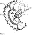
- in einem perspektivischen Schnitt eine weitere Ausführung einer Dreheinrichtungs-Baugruppe für ein Spielzeug, bei der ein Nabenteil mit einem als Radfelge ausgeführten Scheibenteil drehfest verbunden ist; und
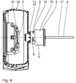
- Fig. 4
- die Dreheinrichtungs-Baugruppe nach
Fig. 3 , bei der das Nabenteil vom Scheibenteil gelöst ist und bei der das Scheibenteil in einem Axialschnitt und das Nabenteil in einer Seitenansicht gezeigt ist. - Eine in der
Fig. 1 insgesamt dargstellte Montage-Baugruppe 1 ist Bestandteil eines Spielzeugs, beispielsweise eines Spielfahrzeugs. Die Montage-Baugruppe 1 hat eine Dreheinrichtungs-Baugruppe 2 und einen Steckschlüssel 3. - Die Dreheinrichtungs-Baugruppe 2 hat eine Achsenkomponente 3a, die eine Drehachse der Dreheinrichtungs-Baugruppe 2 vorgibt. Zudem hat die Dreheinrichtungs-Baugruppe 2 ein Nabenteil 5, das mit der Achsenkomponente 3a verbunden ist, und ein Scheibenteil 6. Beim Scheibenteil 6 kann es sich beispielsweise um eine Radfelge handeln, was nachfolgend insbesondere Bezug nehmend auf die
Fig. 3 und4 noch näher erläutert wird, oder um eine andere drehbare Spielzeugkomponente, beispielsweise um ein Rotorelement oder um ein Rollen-Element, beispielsweise das Rollenteil einer Seilrolle. Das Scheibenteil 6 ist über eine Gewindeverbindung drehfest mit dem Nabenteil 5 verschraubbar. - Diese Gewindeverbindung umfasst ein Außengewinde 7, welches Bestandteil des Nabenteils 5 ist. Das Außengewinde 7 ist als Mehrzahl von voneinander in Umfangsrichtung um die Drehachse 4 beabstandeten Gewindesegmenten 8 ausgeführt. Weiterhin hat die Gewindeverbindung ein zum Außengewinde 7 komplementäres Innengewinde 9, welches Bestandteil des Scheibenteils 6 ist. Das Außengewinde 7 ist am Nabenteil 5 angeformt. Das Innengewinde 9 ist am Scheibenteil 6 angeformt.
- Das Innengewinde 9 hat lediglich einen Gewindegang, der sich um höchstens 360° um die Drehachse 4 erstreckt. Bei der Ausführung nach
Fig. 1 ist diese Umfangserstreckung des Innengewindes 9 kleiner als 360°, wodurch das Scheibenteil 6 insgesamt als einfach entformbares Spritzguss-Kunststoffteil fertigbar ist. - Das Nabenteil 5 hat weiterhin eine Anlagefläche 10 als Widerlager des verschraubten Scheibenteils 6 auf. Bei noch nicht verschraubtem Scheibenteil 6 dient die Anlagefläche 10 zur Positionierung des Scheibenteils 6 am Nabenteil 5.
- Die Anlagefläche 10 umfasst eine Mehrzahl von voneinander in Umfangsrichtung um die Drehachse 4 beabstandeten Anlageflächensegmenten 11. In Umfangsrichtung gesehen sind die Anlageflächensegmente 11 auf Lücke mit den Gewindesegmenten 8 angeordnet. Dies begünstigt ein Entformen des Nabenteils 5 bei der Ausführung als Spritzguss-Kunststoffteil.
- Die Gewindeverbindung mit dem Außengewinde 7 und dem hierzu komplementären Innengewinde 9 ist als Linksgewinde ausgeführt.
- Der Streckschlüssel 3 hat eine Steckschlüssel-Umfangskontur 12, die komplementär zu einer Gegenschlüssel-Kontur 13 des Nabenteils 5 ausgeführt ist. Hierzu hat die Steckschlüssel-Umfangskontur 12 eine Mehrzahl von Auswölbungen, die komplementär zu Mutter-Attrappen 14 gestaltet sind, die wiederum am Nabenteil 5 angeformt sind.
- Zur Montage der Dreheinrichtungs-Baugruppe wird das Scheibenteil 6 auf das Nabenteil 5 aufgesetzt, sodass das Innengewinde 9 des Scheibenteils 6 in Anlage mit den Gewindesegmenten 8 des Außengewindes 7 des Nabenteils 5 gelangt. Hierbei dienen die Anlageflächensegmente 11, an denen das Scheibenteil 6 stirnseitig zu liegen kommt, als Positionierungshilfe. Anschließend wird der Steckschlüssel 3 auf das Nabenteil 5 aufgesetzt, wobei die Steckschlüssel-Umfangskontur 12 die Gegenschlüssel-Kontur 13 des Nabenteils 5 formschlüssig übergreift. Nun wird der Steckschlüssel 3 im Uhrzeigersinn gedreht, wobei ein Betätigungsflügel 15 des Steckschlüssel 3 von der Bedienperson zwischen Daumen und Zeigefinger erfasst wird. Bei dieser Drehbetätigung des Steckschlüssels 3 wird das Nabenteil 5 im Uhrzeigersinn relativ zum festgehaltenen Scheibenteil 6 gedreht. Die Linksgewinde-Gestaltung der Gewindeverbindung sorgt nun dafür, dass das Außengewinde 7 des Nabenteils 5 mit dem Innengewinde 9 des Scheibenteils 6 in Eingriff gelangt. Das Scheibenteil 6 wird bei festgezogener Gewindeverbindung 7, 9 formschlüssig zwischen den Gewindesegmenten 8 und den Anlageflächensegmenten 11 gehalten beziehungsweise geklemmt. Hierdurch ist eine sichere und drehfeste Verbindung zwischen dem Nabenteil 5 und dem Scheibenteil 6 gegeben. Der Steckschlüssel 3 kann dann abgezogen werden. Eine zusätzliche Befestigungsmutter ist nicht erforderlich.
- Anhand der
Fig. 2 wird nachfolgend eine weitere Ausführung einer Montage-Baugruppe 16 erläutert. Komponenten und Funktionen, die denjenigen entsprechen, die vorstehend unter Bezugnahme auf dieFig. 1 bereits erläutert wurden, tragen die gleichen Bezugsziffern und werden nicht nochmals im Einzelnen diskutiert. - Die Montage-Baugruppe 16 hat wiederum ein Nabenteil 5 und ein Scheibenteil 6.
- Das Nabenteil 5 ist bei der Montage-Baugruppe 16 drehbar mit einer Achsenkomponente 17 verbunden, die als Starrachse ausgeführt sein kann. Diese drehbare Verbindung der Achsenkomponente 17 mit dem Nabenteil 5 der Dreheinrichtungs-Baugruppe 2 nach
Fig. 2 ist innerhalb eines Presssitzes der Achsenkomponente 17 im Nabenteil 5 ausgeführt. Diese drehbare Verbindung ist ermöglicht durch eine axiale Profilierung 18 der Achsenkomponente 17, die als Sägezahn-Profilierung ausgeführt ist. DieFig. 2 zeigt diese Profilierung 18 für ein zweites Nabenteil 5, welches identisch zum dargestellten Nabenteil 5 ausgeführt ist und gegengleich auf die Achsenkomponente 17 von der anderen Seite her als Teil einer weiteren Dreheinrichtungs-Baugruppe aufsteckt wird. Aufgrund der Profilierung 18 kann sich das jeweilige Nabenteil 15 relativ zur Achsenkomponente 17 um die Drehachse 4 drehen. - Die Anlagefläche 10 ist bei der Dreheinrichtungs-Baugruppe 2 nach
Fig. 2 als Bestandteil einer Deckenwand eines Nabentopfes 19 des Nabenteils 5 ausgeführt. - Anhand der
Fig. 3 und4 wird nachfolgend eine weitere Ausführung einer Dreheinrichtungs-Baugruppe 20 erläutert. Komponenten und Funktionen, die denjenigen entsprechen, die vorstehend unter Bezugnahme auf dieFig. 1 und2 bereits erläutert wurden, tragen die gleichen Bezugsziffern und werden nicht nochmals im Einzelnen diskutiert. - Bei der Dreheinrichtungs-Baugruppe 20 ist das Scheibenteil als Radfelge 21 eines Spielfahrzeug-Rades 22 ausgeführt.
- Auch für die Dreheinrichtungs-Baugruppe 20 ist ein Steckschlüssel nach Art des Steckschlüssels 3 einsetzbar.
- Bei dem Spielzeug, dessen Bestandteil das Spielfahrzeug-Rad 22 ist, kann es sich um einen Traktor, um einen Lastwagen, um ein Kranfahrzeug oder auch um ein anderes Fahrzeug, beispielsweise einen Anhänger, handeln.
- Die gesamte Montage-Baugruppe 1, 16 sowie die Dreheinrichtungs-Baugruppe 2, 20 kann ausschließlich mit Kunststoffkomponenten gefertigt sein.
Claims (9)
- Dreheinrichtungs-Baugruppe (2; 20) für ein Spielzeug,- mit einer Achsenkomponente (3a; 17), die eine Drehachse (4) der Dreheinrichtungs-Baugruppe (2; 20) vorgibt,- mit einem Nabenteil (5), das mit der Achsenkomponente (3a; 17) verbunden ist, und- mit einem Scheibenteil (6; 21), das über eine Gewindeverbindung drehfest mit dem Nabenteil (5) verschraubbar ist,- wobei das Nabenteil (5) ein Außengewinde (7) der Gewindeverbindung aufweist,- wobei das Scheibenteil (6; 21) ein zum Außengewinde (7) komplementäres Innengewinde (9) der Gewindeverbindung aufweist,- wobei das Innengewinde (9) höchstens einen Gewindegang aufweist,
dadurch gekennzeichnet, dass
es sich bei dem Scheibenteil (6; 21) um ein Rotorteil handelt. - Dreheinrichtungs-Baugruppe nach Anspruch 1, dadurch gekennzeichnet, dass das Nabenteil (5) mindestens eine Anlagefläche (10) als Widerlager des verschraubten Scheibenteils (6; 21) aufweist.
- Dreheinrichtungs-Baugruppe nach Anspruch 1 oder 2, dadurch gekennzeichnet, dass das Nabenteil (5) drehbar mit der Achsenkomponente (17) verbunden ist.
- Dreheinrichtungs-Baugruppe nach einem der Ansprüche 1 bis 3, dadurch gekennzeichnet, dass die Gewindeverbindung als Linksgewinde ausgeführt ist.
- Dreheinrichtungs-Baugruppe nach einem der Ansprüche 1 bis 4, dadurch gekennzeichnet, dass das Außengewinde (7) als Mehrzahl von voneinander in Umfangsrichtung um die Drehachse (4) beabstandeten Gewindesegmenten (8) ausgebildet ist.
- Dreheinrichtungs-Baugruppe nach einem der Ansprüche 2 bis 5, dadurch gekennzeichnet, dass die Anlagefläche (10) eine Mehrzahl von voneinander in Umfangsrichtung um die Drehachse (4) beabstandeten Anlageflächensegmenten (11) aufweist.
- Spielzeug mit einer Dreheinrichtungs-Baugruppe nach einem der Ansprüche 1 bis 6.
- Montage-Baugruppe (1; 16)- mit einer Dreheinrichtungs-Baugruppe nach einem der Ansprüche 1 bis 6, und- mit einem Steckschlüssel (3), der eine Steckschlüssel-Umfangskontur (12) aufweist, die komplementär zu einer Gegenschlüssel-Kontur (13) des Nabenteils (5) ausgeführt ist.
- Steckschlüssel (3) für eine Montage-Baugruppe nach Anspruch 8,- mit einer Steckschlüssel-Umfangskontur (12), die komplementär zu einer Gegenschlüssel-Kontur (13) des Nabenteils (5) ausgeführt ist, und- mit einem Betätigungsflügel (15) zum Erfassen von einer Bedienperson zwischen Daumen und Zeigefinger.
Priority Applications (2)
| Application Number | Priority Date | Filing Date | Title |
|---|---|---|---|
| PL16203080T PL3192575T3 (pl) | 2016-01-14 | 2016-12-09 | Mechaniczny podzespół obrotowy do zabawki |
| HRP20192021TT HRP20192021T1 (hr) | 2016-01-14 | 2019-11-07 | Rotacijski modul za igračku |
Applications Claiming Priority (1)
| Application Number | Priority Date | Filing Date | Title |
|---|---|---|---|
| DE102016200354.2A DE102016200354B4 (de) | 2016-01-14 | 2016-01-14 | Dreheinrichtungs-Baugruppe für ein Spielzeug |
Publications (2)
| Publication Number | Publication Date |
|---|---|
| EP3192575A1 EP3192575A1 (de) | 2017-07-19 |
| EP3192575B1 true EP3192575B1 (de) | 2019-09-04 |
Family
ID=57539115
Family Applications (1)
| Application Number | Title | Priority Date | Filing Date |
|---|---|---|---|
| EP16203080.3A Active EP3192575B1 (de) | 2016-01-14 | 2016-12-09 | Dreheinrichtungs-baugruppe für ein spielzeug |
Country Status (8)
| Country | Link |
|---|---|
| US (1) | US20170203222A1 (de) |
| EP (1) | EP3192575B1 (de) |
| DE (1) | DE102016200354B4 (de) |
| DK (1) | DK3192575T3 (de) |
| ES (1) | ES2758786T3 (de) |
| HR (1) | HRP20192021T1 (de) |
| HU (1) | HUE047590T2 (de) |
| PL (1) | PL3192575T3 (de) |
Families Citing this family (1)
| Publication number | Priority date | Publication date | Assignee | Title |
|---|---|---|---|---|
| DE102019200392B3 (de) | 2019-01-15 | 2020-03-26 | Bruder Spielwaren Gmbh + Co. Kg | Rad-Abziehwerkzeug für ein Spielfahrzeug-Rad |
Family Cites Families (10)
| Publication number | Priority date | Publication date | Assignee | Title |
|---|---|---|---|---|
| US2634168A (en) * | 1948-05-27 | 1953-04-07 | Allen B Maxam | Model airplane wheel |
| US3924352A (en) * | 1975-02-10 | 1975-12-09 | Adolph E Goldfarb | Toy vehicle |
| US4299051A (en) * | 1977-09-09 | 1981-11-10 | Tonka Corporation | Mountable wheel for toy vehicle |
| DK168194B1 (da) * | 1991-11-06 | 1994-02-28 | Lego As | En skrue til et legetøjsbyggesæt |
| DE29800211U1 (de) * | 1998-01-09 | 1998-03-05 | Bruder Spielwaren GmbH & Co. KG, 90768 Fürth | Radanordnung für ein Spielzeugfahrzeug |
| WO2001036063A2 (en) * | 1999-10-29 | 2001-05-25 | Mattel, Inc. | Remote control toy vehicle with power tool |
| US8408962B2 (en) * | 2006-06-05 | 2013-04-02 | Melissa C. Sambenedetto | Toy construction system having a variable angle joint |
| US20130078034A1 (en) * | 2011-09-27 | 2013-03-28 | Konstantinos Kapelonis | Building block |
| DE102013006372B4 (de) * | 2013-04-13 | 2022-06-23 | Volkswagen Aktiengesellschaft | Befestigungsvorrichtung und Befestigungsmutter |
| CN204840929U (zh) * | 2015-06-29 | 2015-12-09 | 罗应源 | 儿童电瓶车发光车轮 |
-
2016
- 2016-01-14 DE DE102016200354.2A patent/DE102016200354B4/de active Active
- 2016-12-09 EP EP16203080.3A patent/EP3192575B1/de active Active
- 2016-12-09 DK DK16203080T patent/DK3192575T3/da active
- 2016-12-09 PL PL16203080T patent/PL3192575T3/pl unknown
- 2016-12-09 HU HUE16203080A patent/HUE047590T2/hu unknown
- 2016-12-09 ES ES16203080T patent/ES2758786T3/es active Active
-
2017
- 2017-01-12 US US15/404,517 patent/US20170203222A1/en not_active Abandoned
-
2019
- 2019-11-07 HR HRP20192021TT patent/HRP20192021T1/hr unknown
Non-Patent Citations (1)
| Title |
|---|
| None * |
Also Published As
| Publication number | Publication date |
|---|---|
| HRP20192021T1 (hr) | 2020-02-07 |
| EP3192575A1 (de) | 2017-07-19 |
| ES2758786T3 (es) | 2020-05-06 |
| DE102016200354B4 (de) | 2024-12-24 |
| DE102016200354A1 (de) | 2017-07-20 |
| DK3192575T3 (da) | 2019-12-02 |
| US20170203222A1 (en) | 2017-07-20 |
| HUE047590T2 (hu) | 2020-04-28 |
| PL3192575T3 (pl) | 2020-02-28 |
Similar Documents
| Publication | Publication Date | Title |
|---|---|---|
| EP0803332B1 (de) | Auspressvorrichtung für ein Achstraggelenk und/oder einen Spurstangenkopf | |
| EP3092134B1 (de) | Zierblende für ein kraftfahrzeugrad, insbesondere für ein leichtmetallrad, sowie verfahren zur befestigung einer zierblende an einem kraftfahrzeugrad | |
| DE102018218484A1 (de) | Endanschlag in einem Lenksystem | |
| WO2013083501A1 (de) | Zweiteiliges rad | |
| DE102015102739B4 (de) | Radmutter und mutterdeckel mit drehbegrenzung | |
| EP3192575B1 (de) | Dreheinrichtungs-baugruppe für ein spielzeug | |
| DE102011051980A1 (de) | Radzentralverschluss | |
| DE602004008954T2 (de) | Anordnung und verfahren zur montage einer radkappe an einem fahrzeug | |
| DE102019107265A1 (de) | Anordnung mit einem Rad und einer Radabdeckung, Verfahren zur Montage, Radabdeckung, Rad, Montagevorrichtung, Kit und Fahrzeug | |
| DE102009017086B4 (de) | Filtertopf mit Drehmomentbegrenzer | |
| DE102020114463B4 (de) | Fahrzeugrad | |
| DE102016209496B4 (de) | Fahrzeugdifferenzialbaugruppe mit kronenförmigem geschwindigkeitsteil zur drehgeschwindigkeitsmessung | |
| EP1892124B1 (de) | Abzieheinrichtung für Felgen | |
| WO2018001726A1 (de) | Achsenend-baugruppe mit einer radnabeneinheit und einer radbremse | |
| DE102008027137A1 (de) | Radverschraubung | |
| EP3138703A1 (de) | Reifendruckkontrollsystem für ein fahrzeug | |
| DE102011115534A1 (de) | Radnabe, Befestigungssystem und Radnabensystem | |
| DE102013000427A1 (de) | Flanschritzel und Herstellungsverfahren dafür sowie spielfreies Stirnrad damit | |
| DE102019002632A1 (de) | Rollbrett | |
| DE102012020208A1 (de) | Radbefestigungsvorrichtung für Spielfahrzeuge, Spielfahrzeug und Radbefestigungwerkzeug | |
| DE102008019738A1 (de) | Selbstsperrendes Differential | |
| DE19500976A1 (de) | Vorrichtung zur Befestigung einer Ausrüstung an der Karosserie eines Kraftfahrzeuges | |
| DE102008008372A1 (de) | Spanneinrichtung zum lösbaren Befestigen eines Teils auf einer Welle | |
| DE102017213273A1 (de) | Radnabenlagereinheit eines Kraftfahrzeugs | |
| DE102006016350A1 (de) | Radkreuz mit integriertem schaltbarem Planetengetriebe |
Legal Events
| Date | Code | Title | Description |
|---|---|---|---|
| PUAI | Public reference made under article 153(3) epc to a published international application that has entered the european phase |
Free format text: ORIGINAL CODE: 0009012 |
|
| STAA | Information on the status of an ep patent application or granted ep patent |
Free format text: STATUS: THE APPLICATION HAS BEEN PUBLISHED |
|
| AK | Designated contracting states |
Kind code of ref document: A1 Designated state(s): AL AT BE BG CH CY CZ DE DK EE ES FI FR GB GR HR HU IE IS IT LI LT LU LV MC MK MT NL NO PL PT RO RS SE SI SK SM TR |
|
| AX | Request for extension of the european patent |
Extension state: BA ME |
|
| STAA | Information on the status of an ep patent application or granted ep patent |
Free format text: STATUS: REQUEST FOR EXAMINATION WAS MADE |
|
| 17P | Request for examination filed |
Effective date: 20171120 |
|
| RBV | Designated contracting states (corrected) |
Designated state(s): AL AT BE BG CH CY CZ DE DK EE ES FI FR GB GR HR HU IE IS IT LI LT LU LV MC MK MT NL NO PL PT RO RS SE SI SK SM TR |
|
| GRAP | Despatch of communication of intention to grant a patent |
Free format text: ORIGINAL CODE: EPIDOSNIGR1 |
|
| STAA | Information on the status of an ep patent application or granted ep patent |
Free format text: STATUS: GRANT OF PATENT IS INTENDED |
|
| INTG | Intention to grant announced |
Effective date: 20190423 |
|
| GRAS | Grant fee paid |
Free format text: ORIGINAL CODE: EPIDOSNIGR3 |
|
| GRAA | (expected) grant |
Free format text: ORIGINAL CODE: 0009210 |
|
| STAA | Information on the status of an ep patent application or granted ep patent |
Free format text: STATUS: THE PATENT HAS BEEN GRANTED |
|
| AK | Designated contracting states |
Kind code of ref document: B1 Designated state(s): AL AT BE BG CH CY CZ DE DK EE ES FI FR GB GR HR HU IE IS IT LI LT LU LV MC MK MT NL NO PL PT RO RS SE SI SK SM TR |
|
| REG | Reference to a national code |
Ref country code: GB Ref legal event code: FG4D Free format text: NOT ENGLISH |
|
| REG | Reference to a national code |
Ref country code: CH Ref legal event code: EP |
|
| REG | Reference to a national code |
Ref country code: AT Ref legal event code: REF Ref document number: 1174551 Country of ref document: AT Kind code of ref document: T Effective date: 20190915 |
|
| REG | Reference to a national code |
Ref country code: DE Ref legal event code: R096 Ref document number: 502016006404 Country of ref document: DE |
|
| REG | Reference to a national code |
Ref country code: IE Ref legal event code: FG4D Free format text: LANGUAGE OF EP DOCUMENT: GERMAN |
|
| REG | Reference to a national code |
Ref country code: HR Ref legal event code: TUEP Ref document number: P20192021T Country of ref document: HR |
|
| REG | Reference to a national code |
Ref country code: RO Ref legal event code: EPE |
|
| REG | Reference to a national code |
Ref country code: DK Ref legal event code: T3 Effective date: 20191127 |
|
| REG | Reference to a national code |
Ref country code: SE Ref legal event code: TRGR |
|
| REG | Reference to a national code |
Ref country code: NL Ref legal event code: FP |
|
| REG | Reference to a national code |
Ref country code: HR Ref legal event code: ODRP Ref document number: P20192021T Country of ref document: HR Payment date: 20191111 Year of fee payment: 4 |
|
| REG | Reference to a national code |
Ref country code: LT Ref legal event code: MG4D Ref country code: NO Ref legal event code: T2 Effective date: 20190904 |
|
| PG25 | Lapsed in a contracting state [announced via postgrant information from national office to epo] |
Ref country code: LT Free format text: LAPSE BECAUSE OF FAILURE TO SUBMIT A TRANSLATION OF THE DESCRIPTION OR TO PAY THE FEE WITHIN THE PRESCRIBED TIME-LIMIT Effective date: 20190904 Ref country code: BG Free format text: LAPSE BECAUSE OF FAILURE TO SUBMIT A TRANSLATION OF THE DESCRIPTION OR TO PAY THE FEE WITHIN THE PRESCRIBED TIME-LIMIT Effective date: 20191204 |
|
| REG | Reference to a national code |
Ref country code: HR Ref legal event code: T1PR Ref document number: P20192021 Country of ref document: HR |
|
| PG25 | Lapsed in a contracting state [announced via postgrant information from national office to epo] |
Ref country code: GR Free format text: LAPSE BECAUSE OF FAILURE TO SUBMIT A TRANSLATION OF THE DESCRIPTION OR TO PAY THE FEE WITHIN THE PRESCRIBED TIME-LIMIT Effective date: 20191205 Ref country code: RS Free format text: LAPSE BECAUSE OF FAILURE TO SUBMIT A TRANSLATION OF THE DESCRIPTION OR TO PAY THE FEE WITHIN THE PRESCRIBED TIME-LIMIT Effective date: 20190904 Ref country code: AL Free format text: LAPSE BECAUSE OF FAILURE TO SUBMIT A TRANSLATION OF THE DESCRIPTION OR TO PAY THE FEE WITHIN THE PRESCRIBED TIME-LIMIT Effective date: 20190904 Ref country code: LV Free format text: LAPSE BECAUSE OF FAILURE TO SUBMIT A TRANSLATION OF THE DESCRIPTION OR TO PAY THE FEE WITHIN THE PRESCRIBED TIME-LIMIT Effective date: 20190904 |
|
| REG | Reference to a national code |
Ref country code: HU Ref legal event code: AG4A Ref document number: E047590 Country of ref document: HU |
|
| PG25 | Lapsed in a contracting state [announced via postgrant information from national office to epo] |
Ref country code: EE Free format text: LAPSE BECAUSE OF FAILURE TO SUBMIT A TRANSLATION OF THE DESCRIPTION OR TO PAY THE FEE WITHIN THE PRESCRIBED TIME-LIMIT Effective date: 20190904 Ref country code: PT Free format text: LAPSE BECAUSE OF FAILURE TO SUBMIT A TRANSLATION OF THE DESCRIPTION OR TO PAY THE FEE WITHIN THE PRESCRIBED TIME-LIMIT Effective date: 20200106 |
|
| REG | Reference to a national code |
Ref country code: ES Ref legal event code: FG2A Ref document number: 2758786 Country of ref document: ES Kind code of ref document: T3 Effective date: 20200506 |
|
| PG25 | Lapsed in a contracting state [announced via postgrant information from national office to epo] |
Ref country code: SK Free format text: LAPSE BECAUSE OF FAILURE TO SUBMIT A TRANSLATION OF THE DESCRIPTION OR TO PAY THE FEE WITHIN THE PRESCRIBED TIME-LIMIT Effective date: 20190904 Ref country code: IS Free format text: LAPSE BECAUSE OF FAILURE TO SUBMIT A TRANSLATION OF THE DESCRIPTION OR TO PAY THE FEE WITHIN THE PRESCRIBED TIME-LIMIT Effective date: 20200224 Ref country code: SM Free format text: LAPSE BECAUSE OF FAILURE TO SUBMIT A TRANSLATION OF THE DESCRIPTION OR TO PAY THE FEE WITHIN THE PRESCRIBED TIME-LIMIT Effective date: 20190904 |
|
| REG | Reference to a national code |
Ref country code: DE Ref legal event code: R097 Ref document number: 502016006404 Country of ref document: DE |
|
| PLBE | No opposition filed within time limit |
Free format text: ORIGINAL CODE: 0009261 |
|
| STAA | Information on the status of an ep patent application or granted ep patent |
Free format text: STATUS: NO OPPOSITION FILED WITHIN TIME LIMIT |
|
| PG2D | Information on lapse in contracting state deleted |
Ref country code: IS |
|
| PG25 | Lapsed in a contracting state [announced via postgrant information from national office to epo] |
Ref country code: IS Free format text: LAPSE BECAUSE OF FAILURE TO SUBMIT A TRANSLATION OF THE DESCRIPTION OR TO PAY THE FEE WITHIN THE PRESCRIBED TIME-LIMIT Effective date: 20200105 |
|
| 26N | No opposition filed |
Effective date: 20200605 |
|
| PG25 | Lapsed in a contracting state [announced via postgrant information from national office to epo] |
Ref country code: MC Free format text: LAPSE BECAUSE OF FAILURE TO SUBMIT A TRANSLATION OF THE DESCRIPTION OR TO PAY THE FEE WITHIN THE PRESCRIBED TIME-LIMIT Effective date: 20190904 Ref country code: SI Free format text: LAPSE BECAUSE OF FAILURE TO SUBMIT A TRANSLATION OF THE DESCRIPTION OR TO PAY THE FEE WITHIN THE PRESCRIBED TIME-LIMIT Effective date: 20190904 |
|
| PG25 | Lapsed in a contracting state [announced via postgrant information from national office to epo] |
Ref country code: IE Free format text: LAPSE BECAUSE OF NON-PAYMENT OF DUE FEES Effective date: 20191209 Ref country code: LU Free format text: LAPSE BECAUSE OF NON-PAYMENT OF DUE FEES Effective date: 20191209 |
|
| REG | Reference to a national code |
Ref country code: HR Ref legal event code: ODRP Ref document number: P20192021 Country of ref document: HR Payment date: 20201203 Year of fee payment: 5 |
|
| PG25 | Lapsed in a contracting state [announced via postgrant information from national office to epo] |
Ref country code: CY Free format text: LAPSE BECAUSE OF FAILURE TO SUBMIT A TRANSLATION OF THE DESCRIPTION OR TO PAY THE FEE WITHIN THE PRESCRIBED TIME-LIMIT Effective date: 20190904 |
|
| PG25 | Lapsed in a contracting state [announced via postgrant information from national office to epo] |
Ref country code: MT Free format text: LAPSE BECAUSE OF FAILURE TO SUBMIT A TRANSLATION OF THE DESCRIPTION OR TO PAY THE FEE WITHIN THE PRESCRIBED TIME-LIMIT Effective date: 20190904 |
|
| REG | Reference to a national code |
Ref country code: HR Ref legal event code: ODRP Ref document number: P20192021 Country of ref document: HR Payment date: 20211202 Year of fee payment: 6 |
|
| PG25 | Lapsed in a contracting state [announced via postgrant information from national office to epo] |
Ref country code: MK Free format text: LAPSE BECAUSE OF FAILURE TO SUBMIT A TRANSLATION OF THE DESCRIPTION OR TO PAY THE FEE WITHIN THE PRESCRIBED TIME-LIMIT Effective date: 20190904 |
|
| REG | Reference to a national code |
Ref country code: HR Ref legal event code: ODRP Ref document number: P20192021 Country of ref document: HR Payment date: 20221130 Year of fee payment: 7 |
|
| P01 | Opt-out of the competence of the unified patent court (upc) registered |
Effective date: 20230519 |
|
| REG | Reference to a national code |
Ref country code: HR Ref legal event code: ODRP Ref document number: P20192021 Country of ref document: HR Payment date: 20231128 Year of fee payment: 8 |
|
| REG | Reference to a national code |
Ref country code: HR Ref legal event code: ODRP Ref document number: P20192021 Country of ref document: HR Payment date: 20241203 Year of fee payment: 9 |
|
| PGFP | Annual fee paid to national office [announced via postgrant information from national office to epo] |
Ref country code: IT Payment date: 20241216 Year of fee payment: 9 |
|
| PGFP | Annual fee paid to national office [announced via postgrant information from national office to epo] |
Ref country code: DE Payment date: 20250221 Year of fee payment: 9 |
|
| PGFP | Annual fee paid to national office [announced via postgrant information from national office to epo] |
Ref country code: ES Payment date: 20250117 Year of fee payment: 9 |
|
| PGFP | Annual fee paid to national office [announced via postgrant information from national office to epo] |
Ref country code: CH Payment date: 20250101 Year of fee payment: 9 |
|
| REG | Reference to a national code |
Ref country code: CH Ref legal event code: U11 Free format text: ST27 STATUS EVENT CODE: U-0-0-U10-U11 (AS PROVIDED BY THE NATIONAL OFFICE) Effective date: 20260101 |
|
| REG | Reference to a national code |
Ref country code: HR Ref legal event code: ODRP Ref document number: P20192021 Country of ref document: HR Payment date: 20251203 Year of fee payment: 10 |
|
| PGFP | Annual fee paid to national office [announced via postgrant information from national office to epo] |
Ref country code: GB Payment date: 20251218 Year of fee payment: 10 |
|
| PGFP | Annual fee paid to national office [announced via postgrant information from national office to epo] |
Ref country code: NO Payment date: 20251216 Year of fee payment: 10 |
|
| PGFP | Annual fee paid to national office [announced via postgrant information from national office to epo] |
Ref country code: AT Payment date: 20251105 Year of fee payment: 10 |
|
| PGFP | Annual fee paid to national office [announced via postgrant information from national office to epo] |
Ref country code: FI Payment date: 20251216 Year of fee payment: 10 Ref country code: DK Payment date: 20251217 Year of fee payment: 10 |
|
| PGFP | Annual fee paid to national office [announced via postgrant information from national office to epo] |
Ref country code: HR Payment date: 20251203 Year of fee payment: 10 Ref country code: HU Payment date: 20251207 Year of fee payment: 10 Ref country code: NL Payment date: 20251217 Year of fee payment: 10 Ref country code: FR Payment date: 20251217 Year of fee payment: 10 |
|
| PGFP | Annual fee paid to national office [announced via postgrant information from national office to epo] |
Ref country code: BE Payment date: 20251223 Year of fee payment: 10 Ref country code: TR Payment date: 20251203 Year of fee payment: 10 |
|
| PGFP | Annual fee paid to national office [announced via postgrant information from national office to epo] |
Ref country code: SE Payment date: 20251217 Year of fee payment: 10 |
|
| PGFP | Annual fee paid to national office [announced via postgrant information from national office to epo] |
Ref country code: CZ Payment date: 20251126 Year of fee payment: 10 |
|
| PGFP | Annual fee paid to national office [announced via postgrant information from national office to epo] |
Ref country code: PL Payment date: 20251118 Year of fee payment: 10 |
|
| PGFP | Annual fee paid to national office [announced via postgrant information from national office to epo] |
Ref country code: RO Payment date: 20251204 Year of fee payment: 10 |