EP3190667B1 - Connector - Google Patents
Connector Download PDFInfo
- Publication number
- EP3190667B1 EP3190667B1 EP16200351.1A EP16200351A EP3190667B1 EP 3190667 B1 EP3190667 B1 EP 3190667B1 EP 16200351 A EP16200351 A EP 16200351A EP 3190667 B1 EP3190667 B1 EP 3190667B1
- Authority
- EP
- European Patent Office
- Prior art keywords
- connector
- mating
- contact
- portions
- lock
- Prior art date
- Legal status (The legal status is an assumption and is not a legal conclusion. Google has not performed a legal analysis and makes no representation as to the accuracy of the status listed.)
- Active
Links
Images


Classifications
-
- H—ELECTRICITY
- H01—ELECTRIC ELEMENTS
- H01R—ELECTRICALLY-CONDUCTIVE CONNECTIONS; STRUCTURAL ASSOCIATIONS OF A PLURALITY OF MUTUALLY-INSULATED ELECTRICAL CONNECTING ELEMENTS; COUPLING DEVICES; CURRENT COLLECTORS
- H01R13/00—Details of coupling devices of the kinds covered by groups H01R12/70 or H01R24/00 - H01R33/00
- H01R13/62—Means for facilitating engagement or disengagement of coupling parts or for holding them in engagement
- H01R13/627—Snap or like fastening
- H01R13/6271—Latching means integral with the housing
- H01R13/6273—Latching means integral with the housing comprising two latching arms
-
- H—ELECTRICITY
- H01—ELECTRIC ELEMENTS
- H01R—ELECTRICALLY-CONDUCTIVE CONNECTIONS; STRUCTURAL ASSOCIATIONS OF A PLURALITY OF MUTUALLY-INSULATED ELECTRICAL CONNECTING ELEMENTS; COUPLING DEVICES; CURRENT COLLECTORS
- H01R13/00—Details of coupling devices of the kinds covered by groups H01R12/70 or H01R24/00 - H01R33/00
- H01R13/62—Means for facilitating engagement or disengagement of coupling parts or for holding them in engagement
- H01R13/627—Snap or like fastening
- H01R13/6271—Latching means integral with the housing
- H01R13/6272—Latching means integral with the housing comprising a single latching arm
-
- H—ELECTRICITY
- H01—ELECTRIC ELEMENTS
- H01R—ELECTRICALLY-CONDUCTIVE CONNECTIONS; STRUCTURAL ASSOCIATIONS OF A PLURALITY OF MUTUALLY-INSULATED ELECTRICAL CONNECTING ELEMENTS; COUPLING DEVICES; CURRENT COLLECTORS
- H01R13/00—Details of coupling devices of the kinds covered by groups H01R12/70 or H01R24/00 - H01R33/00
- H01R13/40—Securing contact members in or to a base or case; Insulating of contact members
- H01R13/42—Securing in a demountable manner
- H01R13/422—Securing in resilient one-piece base or case, e.g. by friction; One-piece base or case formed with resilient locking means
-
- H—ELECTRICITY
- H01—ELECTRIC ELEMENTS
- H01R—ELECTRICALLY-CONDUCTIVE CONNECTIONS; STRUCTURAL ASSOCIATIONS OF A PLURALITY OF MUTUALLY-INSULATED ELECTRICAL CONNECTING ELEMENTS; COUPLING DEVICES; CURRENT COLLECTORS
- H01R13/00—Details of coupling devices of the kinds covered by groups H01R12/70 or H01R24/00 - H01R33/00
- H01R13/44—Means for preventing access to live contacts
-
- H—ELECTRICITY
- H01—ELECTRIC ELEMENTS
- H01R—ELECTRICALLY-CONDUCTIVE CONNECTIONS; STRUCTURAL ASSOCIATIONS OF A PLURALITY OF MUTUALLY-INSULATED ELECTRICAL CONNECTING ELEMENTS; COUPLING DEVICES; CURRENT COLLECTORS
- H01R13/00—Details of coupling devices of the kinds covered by groups H01R12/70 or H01R24/00 - H01R33/00
- H01R13/46—Bases; Cases
-
- H—ELECTRICITY
- H01—ELECTRIC ELEMENTS
- H01R—ELECTRICALLY-CONDUCTIVE CONNECTIONS; STRUCTURAL ASSOCIATIONS OF A PLURALITY OF MUTUALLY-INSULATED ELECTRICAL CONNECTING ELEMENTS; COUPLING DEVICES; CURRENT COLLECTORS
- H01R13/00—Details of coupling devices of the kinds covered by groups H01R12/70 or H01R24/00 - H01R33/00
- H01R13/62—Means for facilitating engagement or disengagement of coupling parts or for holding them in engagement
- H01R13/629—Additional means for facilitating engagement or disengagement of coupling parts, e.g. aligning or guiding means, levers, gas pressure electrical locking indicators, manufacturing tolerances
- H01R13/631—Additional means for facilitating engagement or disengagement of coupling parts, e.g. aligning or guiding means, levers, gas pressure electrical locking indicators, manufacturing tolerances for engagement only
-
- H—ELECTRICITY
- H01—ELECTRIC ELEMENTS
- H01R—ELECTRICALLY-CONDUCTIVE CONNECTIONS; STRUCTURAL ASSOCIATIONS OF A PLURALITY OF MUTUALLY-INSULATED ELECTRICAL CONNECTING ELEMENTS; COUPLING DEVICES; CURRENT COLLECTORS
- H01R4/00—Electrically-conductive connections between two or more conductive members in direct contact, i.e. touching one another; Means for effecting or maintaining such contact; Electrically-conductive connections having two or more spaced connecting locations for conductors and using contact members penetrating insulation
- H01R4/10—Electrically-conductive connections between two or more conductive members in direct contact, i.e. touching one another; Means for effecting or maintaining such contact; Electrically-conductive connections having two or more spaced connecting locations for conductors and using contact members penetrating insulation effected solely by twisting, wrapping, bending, crimping, or other permanent deformation
- H01R4/18—Electrically-conductive connections between two or more conductive members in direct contact, i.e. touching one another; Means for effecting or maintaining such contact; Electrically-conductive connections having two or more spaced connecting locations for conductors and using contact members penetrating insulation effected solely by twisting, wrapping, bending, crimping, or other permanent deformation by crimping
- H01R4/183—Electrically-conductive connections between two or more conductive members in direct contact, i.e. touching one another; Means for effecting or maintaining such contact; Electrically-conductive connections having two or more spaced connecting locations for conductors and using contact members penetrating insulation effected solely by twisting, wrapping, bending, crimping, or other permanent deformation by crimping for cylindrical elongated bodies, e.g. cables having circular cross-section
- H01R4/184—Electrically-conductive connections between two or more conductive members in direct contact, i.e. touching one another; Means for effecting or maintaining such contact; Electrically-conductive connections having two or more spaced connecting locations for conductors and using contact members penetrating insulation effected solely by twisting, wrapping, bending, crimping, or other permanent deformation by crimping for cylindrical elongated bodies, e.g. cables having circular cross-section comprising a U-shaped wire-receiving portion
Definitions
- This invention relates to a connector which is mateable with a mating connector.
- US 5 425 650 A discloses a connector according to the preamble of claim 1 of the present application.
- WO 2009/065051 A1 discloses a latching connector having a locking projection and a counter connector having an alignment projection. No holding portion is provided in the counter connector.
- EP 1 049 213 A1 discloses a male connector having an outer housing, a socket contacts and a housing lock.
- the male connector also has an inner housing which is configured to hold the socket contact.
- the inner housing does not have an H-like cross section. Further, no protrusion portion which protrudes downward in the up-down direction is provided at an inner surface of an upper wall of the outer housing.
- WO 2015/133145 A1 discloses a connector assembly including a plug connector and a receptacle connector.
- the plug connector comprises a plug housing and a plug contact having a tabular contact part.
- the plug housing has a base, a pair of side end cover parts and tip cover part.
- the tip cover part covers a tip of the tabular contact part.
- the plug connector is configured so that the tip of the tabular contact part is prevented from contacting a surface of the tip cover part of the plug housing.
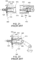
- Patent Document 1 JP-A 2002-056919 discloses a connector 900 which is mateable with a receptacle 950.
- the connector 900 of Patent Document 1 comprises a housing 910 and a male terminal 920 which is held by the housing 910.
- the housing 910 has an upper wall 932 and forms a receiving portion 915.
- An inner surface 935 of the upper wall 932 is provided with a regulating protrusion 925 which protrudes downward.
- An outer surface 940 of the upper wall 932 is provided with a lock portion 930 which protrudes upward.
- the receptacle 950 of Patent Document 1 comprises a female terminal 960 and a receptacle housing 965.
- the receptacle housing 965 has a female terminal accommodation portion 980 and a lock arm 970.
- the female terminal accommodation portion 980 accommodates the female terminal 960.
- the lock arm 970 has a locking lug 975 at an end thereof. The locking lug 975 protrudes downward.
- the regulating protrusion 925 of the connector 900 abuts against the test finger 990. Accordingly, an end of the test finger 990 is prevented from being brought into contact with an end of the male terminal 920.
- the protrusion portion protrudes downward in the up-down direction from the inner surface of the upper wall, and a space exists around the protrusion portion.
- the lock portion is provided on the inner surface of the upper wall by utilizing the space. Accordingly, the connector of the present invention has a function preventing electrical shock and has a reduced size as compared with the connector of Patent Document 1 having the lock portion which protrudes upward from the outer surface of the upper wall of the housing.
- a connector assembly 10 according to an embodiment of the present invention comprises a connector 100 and a mating connector 400.
- the connector 100 is connectable with a cable 700 and is mateable with the mating connector 400 along a front-rear direction. Explanation will be made later about specific connection of the connector 100 and the mating connector 400.
- the front-rear direction is a Y-direction.
- the connector 100 of the present embodiment comprises a housing 200 and a contact 300.
- the housing 200 is made of insulator.
- the contact 300 is made of metal and is held by the housing 200.
- the housing 200 has a fitting portion 210 and a cable holder 260.
- the fitting portion 210 is configured to be mated with the mating connector 400.
- the cable holder 260 is positioned rearward of the fitting portion 210 in the front-rear direction. Rearward is a positive Y-direction, and forward is a negative Y-direction.
- the fitting portion 210 has an upper wall 230, a lower wall 240, two side walls 218 and a rear wall 216.
- the fitting portion 210 forms a receiving portion 250.
- the upper wall 230 is positioned above the lower wall 240 in an up-down direction.
- the up-down direction is a Z-direction. Upward is a positive Z-direction, and downward is a negative Z-direction.
- the two side walls 218 face each other in a lateral direction perpendicular to both the front-rear direction and the up-down direction.
- the lateral direction is an X-direction.
- the rear wall 216 is positioned at a rear end of the fitting portion 210 and is positioned at a front end of the cable holder 260.
- the receiving portion 250 is positioned between the upper wall 230 and the lower wall 240 in the up-down direction.
- the receiving portion 250 is positioned between the two side walls 218 in the lateral direction.
- the receiving portion 250 has an opening 252 which is opened at a front end thereof.
- an inner surface of the upper wall 230 is provided with two lock portions 232 and a protrusion portion 234.
- Each of the lock portions 232 of the present embodiment is a front surface, or a negative Y-side surface, of inside surfaces of a hole which pierces the upper wall 230 in the up-down direction.
- the protrusion portion 234 protrudes downward in the up-down direction and is positioned between the two lock portions 232 in the lateral direction.
- the protrusion portion 234 may, however, not be aligned with each of the lock portions 232 in the front-rear direction.
- the fitting portion 210 is formed with a holding portion 214.
- the holding portion 214 extends forward from the rear wall 216 in the receiving portion 250 and holds the contact 300.
- the holding portion 214 From a perspective plan view of the connector 100 along the up-down direction, the holding portion 214 has an angular C-like shape.
- the holding portion 214 has an H-like cross-section in a plane perpendicular to the front-rear direction.
- the holding portion 214 has an insulating portion 212 which is positioned at a front end of the holding portion 214 in the front-rear direction. In other words, the insulating portion 212 is a part of the holding portion 214. Accordingly, the number of components of the connector 100 can be reduced and the contact 300 can be rigidly held to the housing 200.
- the fitting portion 210 further has two spring accommodation portions 220.
- Each of the spring accommodation portions 220 is positioned at an upper part of the receiving portion 250 and is positioned in the vicinity of the inner surface of the upper wall 230.
- Each of the spring accommodation portions 220 and the protrusion portion 234 are arranged in the lateral direction. In other words, the protrusion portion 234 is positioned between the two spring accommodation portions 220 in the lateral direction.
- the cable holder 260 holds a front end of the cable 700.
- the cable holder 260 has a contact fixing portion 270 by which the contact 300 is fixed to the housing 200.
- the contact fixing portion 270 extends forward and upward.
- a front end of the contact fixing portion 270 is a free end and is resiliently deformable downward.
- the contact 300 according to the invention has a flat shape. Accordingly, in a case where the contact 300 needs to have an increased cross-sectional area in a plane perpendicular to the front-rear direction in order to allow large current flow, the contact 300 can have the increased cross-sectional area by increasing a size of a contact portion 305 in the lateral direction without increasing a size of the contact 300 in the up-down direction, so that the contact 300 having the increased cross-sectional area can allow large current flow. Thus, the connector 100 can be prevented from being increased in size in the up-down direction.
- the contact 300 protrudes in the receiving portion 250 of the fitting portion 210.
- a front end of the contact 300 is brought into abutment with a rear end of the insulating portion 212.
- the contact 300 of the present embodiment has the contact portion 305, a core wire holder 310 and a fixed portion 320.
- the contact portion 305 is positioned in the receiving portion 250 of the fitting portion 210.
- the core wire holder 310 is configured to hold a core wire 710 of the cable 700 and is positioned in the cable holder 260.
- the core wire holder 310 has a U-shaped cross-section in a plane perpendicular to the front-rear direction under a state where the core wire 710 of the cable 700 is not attached to the core wire holder 310.
- the fixed portion 320 is positioned between the contact portion 305 and the core wire holder 310 in the front-rear direction.
- the fixed portion 320 has a shape which slopes downward and rearward.
- the connector 100 is fabricated by attaching the cable 700 to the contact 300, followed by attaching the contact 300 to the housing 200. Specifically, the core wire 710 of the cable 700 is inserted into the core wire holder 310 which is opened to have the U-like shape, and the core wire holder 310 is then crimped around the core wire 710, so that the core wire holder 310 is fixed to the core wire 710.
- the fixed portion 320 of the contact portion 305 of the contact 300 is brought into contact with the contact fixing portion 270 so that the vicinity of the front end of the contact fixing portion 270, or the vicinity of the free end thereof, is pressed to be moved downward.
- a rear end of the fixed portion 320 rides over the free end of the contact fixing portion 270 while the front end of the contact portion 305 of the contact 300 abuts against the rear end of the insulating portion 212.
- the contact fixing portion 270 restores to its original shape by its resilience, and the rear end of the fixed portion 320 and the free end of the contact fixing portion 270 abut against each other in the front-rear direction. Accordingly, the contact 300 is fixed in the housing 200.
- test finger 800 which imitates a user's finger
- the test finger 800 abuts against the protrusion portion 234 before being brought into contact with the contact portion 305 of the contact 300.
- the connector 100 of the present embodiment has the protrusion portion 234, a user's finger is prevented from being brought into contact with the contact 300 when the user's finger is inadvertently inserted into the receiving portion 250.
- the insulating portion 212 of the holding portion 214 is positioned forward beyond the contact portion 305 of the contact 300. Accordingly, in a case where the test finger 800 is inserted into the receiving portion 250, the test finger 800 abuts against the insulating portion 212 before being brought into contact with the contact portion 305 of the contact 300. In other words, since the connector 100 of the present embodiment has the insulating portion 212, a user's a finger is further prevented from being brought into contact with the contact 300 when the user's finger is inadvertently inserted into the receiving portion 250.
- the mating connector 400 is connectable with a cable 750 and is mateable with the connector 100 along the front-rear direction. Explanation will be made later about specific connection of the connector 100 and the mating connector 400.
- the mating connector 400 of the present embodiment comprises a mating housing 500 and a mating contact 600.
- the mating housing 500 has an upper wall 502, a lower wall 504 and two side walls 506. Specifically, the upper wall 502 and the lower wall 504 face each other in the up-down direction, and the two side walls 506 face each other in the lateral direction.
- the upper wall 502 is positioned above the lower wall 504 in the up-down direction.
- the upper wall 502, the lower wall 504 and the two side walls 506 form a connector receiving portion 550.
- the connector receiving portion 550 receives the contact portion 305 and the holding portion 214 of the connector 100 when the connector 100 and the mating connector 400 are mated with each other.
- the mating housing 500 further has two mating lock portions 510, two spring portions 520, a coupling portion 530 and two connecting portions 535.
- the spring portions 520 support the mating lock portions 510, respectively, and the coupling portion 530 couples the spring portions 520 with each other.
- each of the mating lock portions 510 of the present embodiment is a protrusion which protrudes upward. More specifically, each of the mating lock portions 510 has a slope which slopes downward as it extends in the positive Y-direction, and an end of each of the mating lock portions 510 in the negative Y-direction is a plane perpendicular to the front-rear direction. Each of the mating lock portions 510 is positioned on an upper surface of the corresponding spring portion 520 and is positioned in the vicinity of an end of the corresponding spring portion 520 in the negative Y-direction. The two spring portions 520 are positioned away from each other in the lateral direction.
- the coupling portion 530 is positioned beyond the spring portions 520 in the negative Y-direction and is positioned away from an outer surface of the upper wall 502 in the up-down direction.
- the connecting portions 535 are positioned at ends of the spring portions 520, respectively, in the positive Y-direction.
- the connecting portions 535 are positioned in the vicinity of an end of the outer surface of the upper wall 502 in the positive Y-direction.
- Each of the connecting portions 535 connects the corresponding spring portion 520 with the outer surface of the upper wall 502. Since each of the spring portions 520 is resiliently deformable in a state of being fixed to the corresponding connecting portion 535, each of the mating lock portions 510 is movable in the up-down direction.
- the mating housing 500 further has a groove 540 and two mating contact fixing members 562.
- the groove 540 is a portion which receives the protrusion portion 234 of the connector 100 when the connector 100 and the mating connector 400 are mated with each other.
- the groove 540 is positioned between the two spring portions 520 in the lateral direction.
- the lower wall 504 is formed with ditches 505.
- the mating contact fixing members 562 are positioned inward of the ditches 505.
- Each of the mating contact fixing members 562 extends in the positive Y-direction. Specifically, the mating contact fixing members 562 are coupled with the lower wall 504 only at negative Y-side ends thereof.
- the mating contact fixing members 562 are provided with two mating contact fixing portions 560 in the vicinities of positive Y-side ends thereof, respectively.
- each of the mating contact fixing portions 560 protrudes upward.
- the mating contact fixing portions 560 are arranged in the lateral direction. More specifically, each of the mating contact fixing portions 560 has a slope which slopes downward at it extends in the negative Y-direction, and an end of each of the mating contact fixing portions 560 in the positive Y-direction is a plane perpendicular to the front-rear direction.
- Each of the mating contact fixing members 562 is resiliently deformable with the negative Y-side end thereof acting as a fulcrum. Accordingly, each of the mating contact fixing portions 560 is movable in the up-down direction.
- the mating contact 600 has two upper contact portions 612, two lower contact portions 616, a contact portion holder 640, a core wire holder 620 and two fixed portions 630.
- the two upper contact portions 612 are arranged so as to face the two lower contact portions 616, respectively, in the up-down direction.
- Each of the upper contact portions 612 has an upper contact point 614.
- Each of the lower contact portions 616 has a lower contact point 618.
- the contact portion holder 640 holds the two upper contact portions 612 and the two lower contact portions 616.
- the contact portion holder 640 is positioned in the connector receiving portion 550.
- the core wire holder 620 holds a core wire 760 of the cable 750 and is positioned in the mating housing 500.
- the core wire holder 620 has a U-shaped cross-section in a plane perpendicular to the front-rear direction under a state where the core wire 760 of the cable 750 is not attached to the core wire holder 620.
- Each of the fixed portions 630 is a hole which pierces a lower surface of the contact portion holder 640 in the up-down direction.
- the mating connector 400 is fabricated by attaching the cable 750 to the mating contact 600, followed by attaching the mating contact 600 to the mating housing 500. Specifically, the core wire 760 of the cable 750 is inserted into the core wire holder 620 which is opened to have the U-like shape, and the core wire holder 620 is then crimped around the core wire 760, so that the core wire holder 620 is fixed to the core wire 760.
- the lock portions 232 lock the mating lock portions 510, respectively, to lock a mating of the connector 100 with the mating connector 400. More specifically, when the connector 100 and the mating connector 400 are mated with each other, the protrusion of each of the mating lock portions 510 is received in the hole of the corresponding lock portion 232, so that the mating of the connector 100 with the mating connector 400 is locked.
- the connector 100 receives a force which urges the connector 100 to move away from the mating connector 400 in the front-rear direction under the aforementioned state, and/or even if the mating connector 400 receives a force which urge the mating connector 400 to move away from the connector 100 in the front-rear direction under the aforementioned state, the front surface, or the negative Y-side surface, of the inside surfaces of the hole of each of the lock portions 232 abuts against the plane of the protrusion of the corresponding mating lock portion 510 which is positioned at the end thereof in the negative Y-direction. Accordingly, the mated state of the connector 100 with the mating connector 400 is maintained.
- the receiving portion 250 of the connector 100 receives the mating connector 400 when the connector 100 and the mating connector 400 are mated with each other.
- the connector receiving portion 550 of the mating connector 400 receives the contact portion 305 and the holding portion 214 of the connector 100 when the connector 100 and the mating connector 400 are mated with each other.
- the two spring accommodation portions 220 of the connector 100 accommodate the two spring portions 520, respectively, of the mating connector 400 when the connector 100 and the mating connector 400 are mated with each other.
- the protrusion portion 234 of the connector 100 is received in the groove 540 of the mating connector 400 when the connector 100 and the mating connector 400 are mated with each other.
- an upper surface of the contact portion 305 of the contact 300 of the connector 100 is brought into contact with the upper contact points 614 of the upper contact portions 612 of the mating contact 600 of the mating connector 400, and a lower surface of the contact portion 305 of the contact 300 of the connector 100 is brought into contact with the lower contact points 618 of the lower contact portions 616 of the mating contact 600 of the mating connector 400.
- the connector 100 of the aforementioned embodiment has the single protrusion portion 234 and the two lock portions 232
- the connector 100 may have two protrusion portions and a single lock portion which is positioned between the two protrusion portions.
- the two protrusion portions it is, however, necessary for the two protrusion portions to be arranged so that a user's finger can be prevented from being brought into contact with the contact 300 by the user's finger abutting against the two protrusion portions when the user's fihger is inserted into the receiving portion 250.
- each of the lock portions 232 pierces the upper wall 230 in the up-down direction.
- Each of the lock portions may not pierce an upper surface of the upper wall 230 in the up-down direction, provided that the lock portions receive the mating lock portions 510, respectively.
- the lock portion 232 may be a recess which is recessed upward.
- each of the lock portions 232 is the hole which pierces the upper wall 230 in the up-down direction while each of the mating lock portions 510 is the protrusion which protrudes upward.
- the lock portion 232 may be a protrusion which protrudes downward in the up-down direction while the mating lock portion 510 may be a hole, which pierces the spring portion 520 in the up-down direction, or may be a recess which is recessed downward.
- the connector 100 of the aforementioned embodiment is connectable with the cable 700
- the connector 100 may be mountable on a circuit board (not shown).
- the contact 300 of the connector 100 may have a terminal portion for surface mount technology (SMT) or may have a terminal portion for through-hole technology (THT).
Landscapes
- Details Of Connecting Devices For Male And Female Coupling (AREA)
- Connector Housings Or Holding Contact Members (AREA)
- Coupling Device And Connection With Printed Circuit (AREA)
Applications Claiming Priority (1)
| Application Number | Priority Date | Filing Date | Title |
|---|---|---|---|
| JP2016000359A JP6605333B2 (ja) | 2016-01-05 | 2016-01-05 | コネクタ及びコネクタ組立体 |
Publications (2)
| Publication Number | Publication Date |
|---|---|
| EP3190667A1 EP3190667A1 (en) | 2017-07-12 |
| EP3190667B1 true EP3190667B1 (en) | 2020-01-01 |
Family
ID=57391915
Family Applications (1)
| Application Number | Title | Priority Date | Filing Date |
|---|---|---|---|
| EP16200351.1A Active EP3190667B1 (en) | 2016-01-05 | 2016-11-23 | Connector |
Country Status (4)
| Country | Link |
|---|---|
| US (1) | US9787023B2 (enExample) |
| EP (1) | EP3190667B1 (enExample) |
| JP (1) | JP6605333B2 (enExample) |
| CN (1) | CN107017498B (enExample) |
Families Citing this family (10)
| Publication number | Priority date | Publication date | Assignee | Title |
|---|---|---|---|---|
| JP6686804B2 (ja) | 2016-09-05 | 2020-04-22 | 住友電装株式会社 | コネクタ |
| US10873147B2 (en) * | 2016-09-23 | 2020-12-22 | Staubli Electrical Connectors Ag | Protected plug |
| JP6386138B1 (ja) * | 2017-07-14 | 2018-09-05 | 日本航空電子工業株式会社 | コネクタ |
| JP6649937B2 (ja) * | 2017-12-20 | 2020-02-19 | 矢崎総業株式会社 | コネクタ及びコネクタ付き電線 |
| JP6925952B2 (ja) * | 2017-12-20 | 2021-08-25 | ヒロセ電機株式会社 | 電源コネクタ及び電源コネクタ装置 |
| JP6820291B2 (ja) * | 2018-06-19 | 2021-01-27 | 矢崎総業株式会社 | コネクタ装置 |
| CN112313841B (zh) * | 2018-06-25 | 2022-05-31 | 株式会社自动网络技术研究所 | 端子 |
| JP7041104B2 (ja) | 2019-09-24 | 2022-03-23 | 矢崎総業株式会社 | 接続端子及び端子付き電線 |
| JP7670561B2 (ja) * | 2021-06-28 | 2025-04-30 | 日本航空電子工業株式会社 | コネクタ |
| JP7539023B2 (ja) * | 2021-08-27 | 2024-08-23 | 株式会社オートネットワーク技術研究所 | コネクタ |
Citations (1)
| Publication number | Priority date | Publication date | Assignee | Title |
|---|---|---|---|---|
| WO2015133145A1 (ja) * | 2014-03-07 | 2015-09-11 | 日本航空電子工業株式会社 | コネクタ組立体 |
Family Cites Families (27)
| Publication number | Priority date | Publication date | Assignee | Title |
|---|---|---|---|---|
| BR7102123D0 (pt) * | 1971-04-15 | 1973-06-07 | Amp Inc | Conjunto de conector eletrico |
| JP2682596B2 (ja) * | 1993-02-01 | 1997-11-26 | 矢崎総業株式会社 | コネクタのこじり嵌合防止構造 |
| JP3594434B2 (ja) * | 1997-01-08 | 2004-12-02 | ヒロセ電機株式会社 | 回路基板への電気コネクタ取付構造 |
| DE60037292T2 (de) | 1999-04-28 | 2008-10-23 | Yazaki Corp. | Verbindungsvorrichtung für Steckverbinder |
| JP3767779B2 (ja) * | 1999-06-16 | 2006-04-19 | 矢崎総業株式会社 | コネクタのロック機構 |
| JP2001257027A (ja) * | 2000-03-10 | 2001-09-21 | Kanegafuchi Chem Ind Co Ltd | 防滴コネクタ並びにこれを用いた発電機能付き屋根 |
| JP3686827B2 (ja) * | 2000-08-08 | 2005-08-24 | 株式会社オートネットワーク技術研究所 | シールドコネクタ |
| JP3800312B2 (ja) * | 2000-10-31 | 2006-07-26 | 住友電装株式会社 | コネクタ |
| US6790067B2 (en) * | 2002-12-17 | 2004-09-14 | Tyco Electronics Corporation | Finger proof power connector |
| JP4036370B2 (ja) * | 2003-06-02 | 2008-01-23 | 日本航空電子工業株式会社 | 電気コネクタ及びその製造方法 |
| US6830472B1 (en) * | 2003-09-10 | 2004-12-14 | Hon Hai Precision Ind. Co., Ltd. | Cable end connector assembly having locking member |
| US7094089B2 (en) * | 2004-03-12 | 2006-08-22 | Apple Computer, Inc. | DC connector assembly |
| US7057111B2 (en) * | 2004-03-16 | 2006-06-06 | Alex Fung | Cable assembly for electrosurgical pencil |
| US6997748B1 (en) * | 2005-03-07 | 2006-02-14 | Cheng Uei Precision Industry Co., Ltd. | Shielded shell for electronic connector |
| US7083459B1 (en) * | 2005-04-20 | 2006-08-01 | Bizlink Technology, Inc. | Latching connector assembly |
| JP2009123450A (ja) * | 2007-11-14 | 2009-06-04 | Molex Inc | ラッチコネクタ |
| JP5018740B2 (ja) * | 2008-11-10 | 2012-09-05 | 日立電線株式会社 | コネクタ |
| SG166009A1 (en) * | 2009-04-09 | 2010-11-29 | 3M Innovative Properties Co | Electrical connector |
| US8545275B2 (en) * | 2010-04-07 | 2013-10-01 | Alltop Electronics (Suzhou) Ltd. | Electrical connector with touch-safety contact structures |
| JP5516174B2 (ja) | 2010-07-21 | 2014-06-11 | 日立金属株式会社 | コネクタ |
| US9004954B2 (en) * | 2012-03-21 | 2015-04-14 | Delphi Technologies, Inc. | Electrical connection system |
| TWM442618U (en) * | 2012-05-14 | 2012-12-01 | Hon Hai Prec Ind Co Ltd | Electrical connector |
| CN203377434U (zh) * | 2012-09-12 | 2014-01-01 | 连展科技电子(昆山)有限公司 | 连接器插座 |
| JP5965810B2 (ja) * | 2012-10-02 | 2016-08-10 | 矢崎総業株式会社 | 端子及び端子の製造方法 |
| JP6039473B2 (ja) | 2013-03-15 | 2016-12-07 | 日本航空電子工業株式会社 | コネクタ |
| DE102013209690B4 (de) * | 2013-05-24 | 2023-08-03 | Te Connectivity Germany Gmbh | HV-Fingerschutz |
| CN104362451B (zh) * | 2014-11-06 | 2023-05-05 | 连展科技电子(昆山)有限公司 | 具有双向插接功能的插座连接器 |
-
2016
- 2016-01-05 JP JP2016000359A patent/JP6605333B2/ja active Active
- 2016-11-16 US US15/352,863 patent/US9787023B2/en active Active
- 2016-11-23 CN CN201611037315.9A patent/CN107017498B/zh active Active
- 2016-11-23 EP EP16200351.1A patent/EP3190667B1/en active Active
Patent Citations (1)
| Publication number | Priority date | Publication date | Assignee | Title |
|---|---|---|---|---|
| WO2015133145A1 (ja) * | 2014-03-07 | 2015-09-11 | 日本航空電子工業株式会社 | コネクタ組立体 |
Also Published As
| Publication number | Publication date |
|---|---|
| JP6605333B2 (ja) | 2019-11-13 |
| US20170194740A1 (en) | 2017-07-06 |
| EP3190667A1 (en) | 2017-07-12 |
| US9787023B2 (en) | 2017-10-10 |
| CN107017498B (zh) | 2019-06-25 |
| JP2017123223A (ja) | 2017-07-13 |
| CN107017498A (zh) | 2017-08-04 |
Similar Documents
| Publication | Publication Date | Title |
|---|---|---|
| EP3190667B1 (en) | Connector | |
| CN108258484B (zh) | 电连接器及其组合 | |
| CN104078804B (zh) | 连接器 | |
| US6935893B1 (en) | Electrical connector with terminal position assurance device | |
| US7134912B2 (en) | Electrical connector having a shell with a portion which is elastically movable in a fitting portion of the connector | |
| US9300091B2 (en) | Connector with interposed ground plate | |
| US10003148B2 (en) | Connector | |
| EP1833122B1 (en) | Electrical connector terminal housing | |
| KR20160009491A (ko) | 회로 기판용 전기 커넥터 | |
| WO2012127541A1 (ja) | 電線対基板コネクタ | |
| JP2013232309A (ja) | コネクタ | |
| CN101180773B (zh) | 带有闭锁机构的电连接器 | |
| EP3460920B1 (en) | Female terminal and connector | |
| CN114616723B (zh) | 连接器装置 | |
| CN108155503A (zh) | 具备防脱结构的连接器装置 | |
| WO2007016706A2 (en) | Board-to-board connector for mounting on a circuit board | |
| US20210044055A1 (en) | Connector and terminal | |
| US20170093086A1 (en) | Connector and connector assembly | |
| US10826229B2 (en) | Connector with coupling portion | |
| KR200437689Y1 (ko) | 커넥터 | |
| CN212485600U (zh) | 板对板连接器组件 | |
| CN111628317B (zh) | 一种板对板连接器 | |
| KR20220019482A (ko) | 커넥터 및 커넥터조립체 | |
| JP7811361B2 (ja) | コネクタ | |
| EP4024622B1 (en) | Connector assembly |
Legal Events
| Date | Code | Title | Description |
|---|---|---|---|
| PUAI | Public reference made under article 153(3) epc to a published international application that has entered the european phase |
Free format text: ORIGINAL CODE: 0009012 |
|
| STAA | Information on the status of an ep patent application or granted ep patent |
Free format text: STATUS: THE APPLICATION HAS BEEN PUBLISHED |
|
| AK | Designated contracting states |
Kind code of ref document: A1 Designated state(s): AL AT BE BG CH CY CZ DE DK EE ES FI FR GB GR HR HU IE IS IT LI LT LU LV MC MK MT NL NO PL PT RO RS SE SI SK SM TR |
|
| AX | Request for extension of the european patent |
Extension state: BA ME |
|
| STAA | Information on the status of an ep patent application or granted ep patent |
Free format text: STATUS: REQUEST FOR EXAMINATION WAS MADE |
|
| 17P | Request for examination filed |
Effective date: 20170908 |
|
| RBV | Designated contracting states (corrected) |
Designated state(s): AL AT BE BG CH CY CZ DE DK EE ES FI FR GB GR HR HU IE IS IT LI LT LU LV MC MK MT NL NO PL PT RO RS SE SI SK SM TR |
|
| STAA | Information on the status of an ep patent application or granted ep patent |
Free format text: STATUS: EXAMINATION IS IN PROGRESS |
|
| 17Q | First examination report despatched |
Effective date: 20171109 |
|
| GRAP | Despatch of communication of intention to grant a patent |
Free format text: ORIGINAL CODE: EPIDOSNIGR1 |
|
| STAA | Information on the status of an ep patent application or granted ep patent |
Free format text: STATUS: GRANT OF PATENT IS INTENDED |
|
| INTG | Intention to grant announced |
Effective date: 20190618 |
|
| GRAS | Grant fee paid |
Free format text: ORIGINAL CODE: EPIDOSNIGR3 |
|
| GRAA | (expected) grant |
Free format text: ORIGINAL CODE: 0009210 |
|
| STAA | Information on the status of an ep patent application or granted ep patent |
Free format text: STATUS: THE PATENT HAS BEEN GRANTED |
|
| AK | Designated contracting states |
Kind code of ref document: B1 Designated state(s): AL AT BE BG CH CY CZ DE DK EE ES FI FR GB GR HR HU IE IS IT LI LT LU LV MC MK MT NL NO PL PT RO RS SE SI SK SM TR |
|
| REG | Reference to a national code |
Ref country code: GB Ref legal event code: FG4D |
|
| REG | Reference to a national code |
Ref country code: CH Ref legal event code: EP Ref country code: AT Ref legal event code: REF Ref document number: 1220968 Country of ref document: AT Kind code of ref document: T Effective date: 20200115 |
|
| REG | Reference to a national code |
Ref country code: IE Ref legal event code: FG4D |
|
| REG | Reference to a national code |
Ref country code: DE Ref legal event code: R096 Ref document number: 602016027234 Country of ref document: DE |
|
| REG | Reference to a national code |
Ref country code: NL Ref legal event code: MP Effective date: 20200101 |
|
| REG | Reference to a national code |
Ref country code: LT Ref legal event code: MG4D |
|
| PG25 | Lapsed in a contracting state [announced via postgrant information from national office to epo] |
Ref country code: PT Free format text: LAPSE BECAUSE OF FAILURE TO SUBMIT A TRANSLATION OF THE DESCRIPTION OR TO PAY THE FEE WITHIN THE PRESCRIBED TIME-LIMIT Effective date: 20200527 Ref country code: NO Free format text: LAPSE BECAUSE OF FAILURE TO SUBMIT A TRANSLATION OF THE DESCRIPTION OR TO PAY THE FEE WITHIN THE PRESCRIBED TIME-LIMIT Effective date: 20200401 Ref country code: RS Free format text: LAPSE BECAUSE OF FAILURE TO SUBMIT A TRANSLATION OF THE DESCRIPTION OR TO PAY THE FEE WITHIN THE PRESCRIBED TIME-LIMIT Effective date: 20200101 Ref country code: FI Free format text: LAPSE BECAUSE OF FAILURE TO SUBMIT A TRANSLATION OF THE DESCRIPTION OR TO PAY THE FEE WITHIN THE PRESCRIBED TIME-LIMIT Effective date: 20200101 Ref country code: LT Free format text: LAPSE BECAUSE OF FAILURE TO SUBMIT A TRANSLATION OF THE DESCRIPTION OR TO PAY THE FEE WITHIN THE PRESCRIBED TIME-LIMIT Effective date: 20200101 Ref country code: NL Free format text: LAPSE BECAUSE OF FAILURE TO SUBMIT A TRANSLATION OF THE DESCRIPTION OR TO PAY THE FEE WITHIN THE PRESCRIBED TIME-LIMIT Effective date: 20200101 Ref country code: CZ Free format text: LAPSE BECAUSE OF FAILURE TO SUBMIT A TRANSLATION OF THE DESCRIPTION OR TO PAY THE FEE WITHIN THE PRESCRIBED TIME-LIMIT Effective date: 20200101 |
|
| PG25 | Lapsed in a contracting state [announced via postgrant information from national office to epo] |
Ref country code: BG Free format text: LAPSE BECAUSE OF FAILURE TO SUBMIT A TRANSLATION OF THE DESCRIPTION OR TO PAY THE FEE WITHIN THE PRESCRIBED TIME-LIMIT Effective date: 20200401 Ref country code: GR Free format text: LAPSE BECAUSE OF FAILURE TO SUBMIT A TRANSLATION OF THE DESCRIPTION OR TO PAY THE FEE WITHIN THE PRESCRIBED TIME-LIMIT Effective date: 20200402 Ref country code: IS Free format text: LAPSE BECAUSE OF FAILURE TO SUBMIT A TRANSLATION OF THE DESCRIPTION OR TO PAY THE FEE WITHIN THE PRESCRIBED TIME-LIMIT Effective date: 20200501 Ref country code: SE Free format text: LAPSE BECAUSE OF FAILURE TO SUBMIT A TRANSLATION OF THE DESCRIPTION OR TO PAY THE FEE WITHIN THE PRESCRIBED TIME-LIMIT Effective date: 20200101 Ref country code: LV Free format text: LAPSE BECAUSE OF FAILURE TO SUBMIT A TRANSLATION OF THE DESCRIPTION OR TO PAY THE FEE WITHIN THE PRESCRIBED TIME-LIMIT Effective date: 20200101 Ref country code: HR Free format text: LAPSE BECAUSE OF FAILURE TO SUBMIT A TRANSLATION OF THE DESCRIPTION OR TO PAY THE FEE WITHIN THE PRESCRIBED TIME-LIMIT Effective date: 20200101 |
|
| REG | Reference to a national code |
Ref country code: DE Ref legal event code: R097 Ref document number: 602016027234 Country of ref document: DE |
|
| PG25 | Lapsed in a contracting state [announced via postgrant information from national office to epo] |
Ref country code: ES Free format text: LAPSE BECAUSE OF FAILURE TO SUBMIT A TRANSLATION OF THE DESCRIPTION OR TO PAY THE FEE WITHIN THE PRESCRIBED TIME-LIMIT Effective date: 20200101 Ref country code: SK Free format text: LAPSE BECAUSE OF FAILURE TO SUBMIT A TRANSLATION OF THE DESCRIPTION OR TO PAY THE FEE WITHIN THE PRESCRIBED TIME-LIMIT Effective date: 20200101 Ref country code: DK Free format text: LAPSE BECAUSE OF FAILURE TO SUBMIT A TRANSLATION OF THE DESCRIPTION OR TO PAY THE FEE WITHIN THE PRESCRIBED TIME-LIMIT Effective date: 20200101 Ref country code: RO Free format text: LAPSE BECAUSE OF FAILURE TO SUBMIT A TRANSLATION OF THE DESCRIPTION OR TO PAY THE FEE WITHIN THE PRESCRIBED TIME-LIMIT Effective date: 20200101 Ref country code: EE Free format text: LAPSE BECAUSE OF FAILURE TO SUBMIT A TRANSLATION OF THE DESCRIPTION OR TO PAY THE FEE WITHIN THE PRESCRIBED TIME-LIMIT Effective date: 20200101 Ref country code: SM Free format text: LAPSE BECAUSE OF FAILURE TO SUBMIT A TRANSLATION OF THE DESCRIPTION OR TO PAY THE FEE WITHIN THE PRESCRIBED TIME-LIMIT Effective date: 20200101 |
|
| PLBE | No opposition filed within time limit |
Free format text: ORIGINAL CODE: 0009261 |
|
| STAA | Information on the status of an ep patent application or granted ep patent |
Free format text: STATUS: NO OPPOSITION FILED WITHIN TIME LIMIT |
|
| REG | Reference to a national code |
Ref country code: AT Ref legal event code: MK05 Ref document number: 1220968 Country of ref document: AT Kind code of ref document: T Effective date: 20200101 |
|
| 26N | No opposition filed |
Effective date: 20201002 |
|
| PG25 | Lapsed in a contracting state [announced via postgrant information from national office to epo] |
Ref country code: AT Free format text: LAPSE BECAUSE OF FAILURE TO SUBMIT A TRANSLATION OF THE DESCRIPTION OR TO PAY THE FEE WITHIN THE PRESCRIBED TIME-LIMIT Effective date: 20200101 Ref country code: IT Free format text: LAPSE BECAUSE OF FAILURE TO SUBMIT A TRANSLATION OF THE DESCRIPTION OR TO PAY THE FEE WITHIN THE PRESCRIBED TIME-LIMIT Effective date: 20200101 |
|
| PG25 | Lapsed in a contracting state [announced via postgrant information from national office to epo] |
Ref country code: PL Free format text: LAPSE BECAUSE OF FAILURE TO SUBMIT A TRANSLATION OF THE DESCRIPTION OR TO PAY THE FEE WITHIN THE PRESCRIBED TIME-LIMIT Effective date: 20200101 Ref country code: SI Free format text: LAPSE BECAUSE OF FAILURE TO SUBMIT A TRANSLATION OF THE DESCRIPTION OR TO PAY THE FEE WITHIN THE PRESCRIBED TIME-LIMIT Effective date: 20200101 |
|
| PG25 | Lapsed in a contracting state [announced via postgrant information from national office to epo] |
Ref country code: MC Free format text: LAPSE BECAUSE OF FAILURE TO SUBMIT A TRANSLATION OF THE DESCRIPTION OR TO PAY THE FEE WITHIN THE PRESCRIBED TIME-LIMIT Effective date: 20200101 |
|
| REG | Reference to a national code |
Ref country code: CH Ref legal event code: PL |
|
| GBPC | Gb: european patent ceased through non-payment of renewal fee |
Effective date: 20201123 |
|
| PG25 | Lapsed in a contracting state [announced via postgrant information from national office to epo] |
Ref country code: LU Free format text: LAPSE BECAUSE OF NON-PAYMENT OF DUE FEES Effective date: 20201123 |
|
| REG | Reference to a national code |
Ref country code: BE Ref legal event code: MM Effective date: 20201130 |
|
| PG25 | Lapsed in a contracting state [announced via postgrant information from national office to epo] |
Ref country code: CH Free format text: LAPSE BECAUSE OF NON-PAYMENT OF DUE FEES Effective date: 20201130 Ref country code: LI Free format text: LAPSE BECAUSE OF NON-PAYMENT OF DUE FEES Effective date: 20201130 |
|
| PG25 | Lapsed in a contracting state [announced via postgrant information from national office to epo] |
Ref country code: FR Free format text: LAPSE BECAUSE OF NON-PAYMENT OF DUE FEES Effective date: 20201130 Ref country code: IE Free format text: LAPSE BECAUSE OF NON-PAYMENT OF DUE FEES Effective date: 20201123 |
|
| PG25 | Lapsed in a contracting state [announced via postgrant information from national office to epo] |
Ref country code: GB Free format text: LAPSE BECAUSE OF NON-PAYMENT OF DUE FEES Effective date: 20201123 |
|
| PG25 | Lapsed in a contracting state [announced via postgrant information from national office to epo] |
Ref country code: TR Free format text: LAPSE BECAUSE OF FAILURE TO SUBMIT A TRANSLATION OF THE DESCRIPTION OR TO PAY THE FEE WITHIN THE PRESCRIBED TIME-LIMIT Effective date: 20200101 Ref country code: MT Free format text: LAPSE BECAUSE OF FAILURE TO SUBMIT A TRANSLATION OF THE DESCRIPTION OR TO PAY THE FEE WITHIN THE PRESCRIBED TIME-LIMIT Effective date: 20200101 Ref country code: CY Free format text: LAPSE BECAUSE OF FAILURE TO SUBMIT A TRANSLATION OF THE DESCRIPTION OR TO PAY THE FEE WITHIN THE PRESCRIBED TIME-LIMIT Effective date: 20200101 |
|
| PG25 | Lapsed in a contracting state [announced via postgrant information from national office to epo] |
Ref country code: MK Free format text: LAPSE BECAUSE OF FAILURE TO SUBMIT A TRANSLATION OF THE DESCRIPTION OR TO PAY THE FEE WITHIN THE PRESCRIBED TIME-LIMIT Effective date: 20200101 Ref country code: AL Free format text: LAPSE BECAUSE OF FAILURE TO SUBMIT A TRANSLATION OF THE DESCRIPTION OR TO PAY THE FEE WITHIN THE PRESCRIBED TIME-LIMIT Effective date: 20200101 |
|
| PG25 | Lapsed in a contracting state [announced via postgrant information from national office to epo] |
Ref country code: BE Free format text: LAPSE BECAUSE OF NON-PAYMENT OF DUE FEES Effective date: 20201130 |
|
| PGFP | Annual fee paid to national office [announced via postgrant information from national office to epo] |
Ref country code: DE Payment date: 20250930 Year of fee payment: 10 |