EP3186455B1 - Systèmes de charpente pour structures de construction - Google Patents
Systèmes de charpente pour structures de construction Download PDFInfo
- Publication number
- EP3186455B1 EP3186455B1 EP15819176.7A EP15819176A EP3186455B1 EP 3186455 B1 EP3186455 B1 EP 3186455B1 EP 15819176 A EP15819176 A EP 15819176A EP 3186455 B1 EP3186455 B1 EP 3186455B1
- Authority
- EP
- European Patent Office
- Prior art keywords
- flanges
- spreader
- members
- assembly
- frame system
- Prior art date
- Legal status (The legal status is an assumption and is not a legal conclusion. Google has not performed a legal analysis and makes no representation as to the accuracy of the status listed.)
- Active
Links
- 238000000034 method Methods 0.000 claims description 29
- 239000000463 material Substances 0.000 claims description 17
- 238000004080 punching Methods 0.000 claims description 16
- 239000002184 metal Substances 0.000 claims description 13
- 229910052751 metal Inorganic materials 0.000 claims description 13
- 238000012856 packing Methods 0.000 claims description 7
- 238000007493 shaping process Methods 0.000 claims description 6
- 239000000758 substrate Substances 0.000 claims description 3
- 210000000006 pectoral fin Anatomy 0.000 description 25
- 230000000712 assembly Effects 0.000 description 12
- 238000000429 assembly Methods 0.000 description 12
- 230000008569 process Effects 0.000 description 10
- 229910000831 Steel Inorganic materials 0.000 description 9
- 239000010959 steel Substances 0.000 description 9
- 230000015572 biosynthetic process Effects 0.000 description 7
- 230000006870 function Effects 0.000 description 4
- 238000010276 construction Methods 0.000 description 3
- 238000009826 distribution Methods 0.000 description 3
- 238000012986 modification Methods 0.000 description 2
- 230000004048 modification Effects 0.000 description 2
- 230000000284 resting effect Effects 0.000 description 2
- 230000007704 transition Effects 0.000 description 2
- 238000003491 array Methods 0.000 description 1
- 238000005452 bending Methods 0.000 description 1
- 230000008901 benefit Effects 0.000 description 1
- 238000005253 cladding Methods 0.000 description 1
- 238000005520 cutting process Methods 0.000 description 1
- 239000012530 fluid Substances 0.000 description 1
- 238000011835 investigation Methods 0.000 description 1
- 150000002739 metals Chemical class 0.000 description 1
- 238000003825 pressing Methods 0.000 description 1
- 230000009467 reduction Effects 0.000 description 1
- 239000012858 resilient material Substances 0.000 description 1
- 230000000717 retained effect Effects 0.000 description 1
- 238000012358 sourcing Methods 0.000 description 1
Images


Classifications
-
- B—PERFORMING OPERATIONS; TRANSPORTING
- B21—MECHANICAL METAL-WORKING WITHOUT ESSENTIALLY REMOVING MATERIAL; PUNCHING METAL
- B21D—WORKING OR PROCESSING OF SHEET METAL OR METAL TUBES, RODS OR PROFILES WITHOUT ESSENTIALLY REMOVING MATERIAL; PUNCHING METAL
- B21D5/00—Bending sheet metal along straight lines, e.g. to form simple curves
- B21D5/06—Bending sheet metal along straight lines, e.g. to form simple curves by drawing procedure making use of dies or forming-rollers, e.g. making profiles
-
- E—FIXED CONSTRUCTIONS
- E04—BUILDING
- E04B—GENERAL BUILDING CONSTRUCTIONS; WALLS, e.g. PARTITIONS; ROOFS; FLOORS; CEILINGS; INSULATION OR OTHER PROTECTION OF BUILDINGS
- E04B1/00—Constructions in general; Structures which are not restricted either to walls, e.g. partitions, or floors or ceilings or roofs
- E04B1/18—Structures comprising elongated load-supporting parts, e.g. columns, girders, skeletons
- E04B1/19—Three-dimensional framework structures
-
- B—PERFORMING OPERATIONS; TRANSPORTING
- B21—MECHANICAL METAL-WORKING WITHOUT ESSENTIALLY REMOVING MATERIAL; PUNCHING METAL
- B21D—WORKING OR PROCESSING OF SHEET METAL OR METAL TUBES, RODS OR PROFILES WITHOUT ESSENTIALLY REMOVING MATERIAL; PUNCHING METAL
- B21D35/00—Combined processes according to or processes combined with methods covered by groups B21D1/00 - B21D31/00
- B21D35/001—Shaping combined with punching, e.g. stamping and perforating
-
- B—PERFORMING OPERATIONS; TRANSPORTING
- B21—MECHANICAL METAL-WORKING WITHOUT ESSENTIALLY REMOVING MATERIAL; PUNCHING METAL
- B21D—WORKING OR PROCESSING OF SHEET METAL OR METAL TUBES, RODS OR PROFILES WITHOUT ESSENTIALLY REMOVING MATERIAL; PUNCHING METAL
- B21D47/00—Making rigid structural elements or units, e.g. honeycomb structures
- B21D47/01—Making rigid structural elements or units, e.g. honeycomb structures beams or pillars
-
- E—FIXED CONSTRUCTIONS
- E04—BUILDING
- E04B—GENERAL BUILDING CONSTRUCTIONS; WALLS, e.g. PARTITIONS; ROOFS; FLOORS; CEILINGS; INSULATION OR OTHER PROTECTION OF BUILDINGS
- E04B1/00—Constructions in general; Structures which are not restricted either to walls, e.g. partitions, or floors or ceilings or roofs
- E04B1/18—Structures comprising elongated load-supporting parts, e.g. columns, girders, skeletons
- E04B1/24—Structures comprising elongated load-supporting parts, e.g. columns, girders, skeletons the supporting parts consisting of metal
- E04B1/2403—Connection details of the elongated load-supporting parts
-
- E—FIXED CONSTRUCTIONS
- E04—BUILDING
- E04B—GENERAL BUILDING CONSTRUCTIONS; WALLS, e.g. PARTITIONS; ROOFS; FLOORS; CEILINGS; INSULATION OR OTHER PROTECTION OF BUILDINGS
- E04B1/00—Constructions in general; Structures which are not restricted either to walls, e.g. partitions, or floors or ceilings or roofs
- E04B1/35—Extraordinary methods of construction, e.g. lift-slab, jack-block
- E04B1/3511—Lift-slab; characterised by a purely vertical lifting of floors or roofs or parts thereof
-
- E—FIXED CONSTRUCTIONS
- E04—BUILDING
- E04B—GENERAL BUILDING CONSTRUCTIONS; WALLS, e.g. PARTITIONS; ROOFS; FLOORS; CEILINGS; INSULATION OR OTHER PROTECTION OF BUILDINGS
- E04B1/00—Constructions in general; Structures which are not restricted either to walls, e.g. partitions, or floors or ceilings or roofs
- E04B1/35—Extraordinary methods of construction, e.g. lift-slab, jack-block
- E04B1/3522—Extraordinary methods of construction, e.g. lift-slab, jack-block characterised by raising a structure and then adding structural elements under it
- E04B1/3527—Extraordinary methods of construction, e.g. lift-slab, jack-block characterised by raising a structure and then adding structural elements under it the structure being a roof
-
- E—FIXED CONSTRUCTIONS
- E04—BUILDING
- E04B—GENERAL BUILDING CONSTRUCTIONS; WALLS, e.g. PARTITIONS; ROOFS; FLOORS; CEILINGS; INSULATION OR OTHER PROTECTION OF BUILDINGS
- E04B2/00—Walls, e.g. partitions, for buildings; Wall construction with regard to insulation; Connections specially adapted to walls
- E04B2/56—Load-bearing walls of framework or pillarwork; Walls incorporating load-bearing elongated members
- E04B2/58—Load-bearing walls of framework or pillarwork; Walls incorporating load-bearing elongated members with elongated members of metal
- E04B2/60—Load-bearing walls of framework or pillarwork; Walls incorporating load-bearing elongated members with elongated members of metal characterised by special cross-section of the elongated members
-
- E—FIXED CONSTRUCTIONS
- E04—BUILDING
- E04B—GENERAL BUILDING CONSTRUCTIONS; WALLS, e.g. PARTITIONS; ROOFS; FLOORS; CEILINGS; INSULATION OR OTHER PROTECTION OF BUILDINGS
- E04B5/00—Floors; Floor construction with regard to insulation; Connections specially adapted therefor
- E04B5/02—Load-carrying floor structures formed substantially of prefabricated units
- E04B5/10—Load-carrying floor structures formed substantially of prefabricated units with metal beams or girders, e.g. with steel lattice girders
-
- E—FIXED CONSTRUCTIONS
- E04—BUILDING
- E04B—GENERAL BUILDING CONSTRUCTIONS; WALLS, e.g. PARTITIONS; ROOFS; FLOORS; CEILINGS; INSULATION OR OTHER PROTECTION OF BUILDINGS
- E04B5/00—Floors; Floor construction with regard to insulation; Connections specially adapted therefor
- E04B5/02—Load-carrying floor structures formed substantially of prefabricated units
- E04B5/14—Load-carrying floor structures formed substantially of prefabricated units with beams or girders laid in two directions
-
- E—FIXED CONSTRUCTIONS
- E04—BUILDING
- E04B—GENERAL BUILDING CONSTRUCTIONS; WALLS, e.g. PARTITIONS; ROOFS; FLOORS; CEILINGS; INSULATION OR OTHER PROTECTION OF BUILDINGS
- E04B7/00—Roofs; Roof construction with regard to insulation
- E04B7/02—Roofs; Roof construction with regard to insulation with plane sloping surfaces, e.g. saddle roofs
- E04B7/04—Roofs; Roof construction with regard to insulation with plane sloping surfaces, e.g. saddle roofs supported by horizontal beams or the equivalent resting on the walls
-
- E—FIXED CONSTRUCTIONS
- E04—BUILDING
- E04C—STRUCTURAL ELEMENTS; BUILDING MATERIALS
- E04C3/00—Structural elongated elements designed for load-supporting
- E04C3/02—Joists; Girders, trusses, or trusslike structures, e.g. prefabricated; Lintels; Transoms; Braces
- E04C3/04—Joists; Girders, trusses, or trusslike structures, e.g. prefabricated; Lintels; Transoms; Braces of metal
- E04C3/08—Joists; Girders, trusses, or trusslike structures, e.g. prefabricated; Lintels; Transoms; Braces of metal with apertured web, e.g. with a web consisting of bar-like components; Honeycomb girders
- E04C3/083—Honeycomb girders; Girders with apertured solid web
-
- E—FIXED CONSTRUCTIONS
- E04—BUILDING
- E04C—STRUCTURAL ELEMENTS; BUILDING MATERIALS
- E04C3/00—Structural elongated elements designed for load-supporting
- E04C3/02—Joists; Girders, trusses, or trusslike structures, e.g. prefabricated; Lintels; Transoms; Braces
- E04C3/04—Joists; Girders, trusses, or trusslike structures, e.g. prefabricated; Lintels; Transoms; Braces of metal
- E04C3/08—Joists; Girders, trusses, or trusslike structures, e.g. prefabricated; Lintels; Transoms; Braces of metal with apertured web, e.g. with a web consisting of bar-like components; Honeycomb girders
- E04C3/09—Joists; Girders, trusses, or trusslike structures, e.g. prefabricated; Lintels; Transoms; Braces of metal with apertured web, e.g. with a web consisting of bar-like components; Honeycomb girders at least partly of bent or otherwise deformed strip- or sheet-like material
-
- E—FIXED CONSTRUCTIONS
- E04—BUILDING
- E04C—STRUCTURAL ELEMENTS; BUILDING MATERIALS
- E04C3/00—Structural elongated elements designed for load-supporting
- E04C3/30—Columns; Pillars; Struts
- E04C3/32—Columns; Pillars; Struts of metal
-
- E—FIXED CONSTRUCTIONS
- E04—BUILDING
- E04B—GENERAL BUILDING CONSTRUCTIONS; WALLS, e.g. PARTITIONS; ROOFS; FLOORS; CEILINGS; INSULATION OR OTHER PROTECTION OF BUILDINGS
- E04B1/00—Constructions in general; Structures which are not restricted either to walls, e.g. partitions, or floors or ceilings or roofs
- E04B1/18—Structures comprising elongated load-supporting parts, e.g. columns, girders, skeletons
- E04B1/19—Three-dimensional framework structures
- E04B2001/1957—Details of connections between nodes and struts
-
- E—FIXED CONSTRUCTIONS
- E04—BUILDING
- E04B—GENERAL BUILDING CONSTRUCTIONS; WALLS, e.g. PARTITIONS; ROOFS; FLOORS; CEILINGS; INSULATION OR OTHER PROTECTION OF BUILDINGS
- E04B1/00—Constructions in general; Structures which are not restricted either to walls, e.g. partitions, or floors or ceilings or roofs
- E04B1/18—Structures comprising elongated load-supporting parts, e.g. columns, girders, skeletons
- E04B1/24—Structures comprising elongated load-supporting parts, e.g. columns, girders, skeletons the supporting parts consisting of metal
- E04B1/2403—Connection details of the elongated load-supporting parts
- E04B2001/2415—Brackets, gussets, joining plates
-
- E—FIXED CONSTRUCTIONS
- E04—BUILDING
- E04B—GENERAL BUILDING CONSTRUCTIONS; WALLS, e.g. PARTITIONS; ROOFS; FLOORS; CEILINGS; INSULATION OR OTHER PROTECTION OF BUILDINGS
- E04B1/00—Constructions in general; Structures which are not restricted either to walls, e.g. partitions, or floors or ceilings or roofs
- E04B1/18—Structures comprising elongated load-supporting parts, e.g. columns, girders, skeletons
- E04B1/24—Structures comprising elongated load-supporting parts, e.g. columns, girders, skeletons the supporting parts consisting of metal
- E04B1/2403—Connection details of the elongated load-supporting parts
- E04B2001/2418—Details of bolting
-
- E—FIXED CONSTRUCTIONS
- E04—BUILDING
- E04B—GENERAL BUILDING CONSTRUCTIONS; WALLS, e.g. PARTITIONS; ROOFS; FLOORS; CEILINGS; INSULATION OR OTHER PROTECTION OF BUILDINGS
- E04B1/00—Constructions in general; Structures which are not restricted either to walls, e.g. partitions, or floors or ceilings or roofs
- E04B1/18—Structures comprising elongated load-supporting parts, e.g. columns, girders, skeletons
- E04B1/24—Structures comprising elongated load-supporting parts, e.g. columns, girders, skeletons the supporting parts consisting of metal
- E04B1/2403—Connection details of the elongated load-supporting parts
- E04B2001/2448—Connections between open section profiles
-
- E—FIXED CONSTRUCTIONS
- E04—BUILDING
- E04B—GENERAL BUILDING CONSTRUCTIONS; WALLS, e.g. PARTITIONS; ROOFS; FLOORS; CEILINGS; INSULATION OR OTHER PROTECTION OF BUILDINGS
- E04B1/00—Constructions in general; Structures which are not restricted either to walls, e.g. partitions, or floors or ceilings or roofs
- E04B1/18—Structures comprising elongated load-supporting parts, e.g. columns, girders, skeletons
- E04B1/24—Structures comprising elongated load-supporting parts, e.g. columns, girders, skeletons the supporting parts consisting of metal
- E04B1/2403—Connection details of the elongated load-supporting parts
- E04B2001/2454—Connections between open and closed section profiles
-
- E—FIXED CONSTRUCTIONS
- E04—BUILDING
- E04B—GENERAL BUILDING CONSTRUCTIONS; WALLS, e.g. PARTITIONS; ROOFS; FLOORS; CEILINGS; INSULATION OR OTHER PROTECTION OF BUILDINGS
- E04B1/00—Constructions in general; Structures which are not restricted either to walls, e.g. partitions, or floors or ceilings or roofs
- E04B1/18—Structures comprising elongated load-supporting parts, e.g. columns, girders, skeletons
- E04B1/24—Structures comprising elongated load-supporting parts, e.g. columns, girders, skeletons the supporting parts consisting of metal
- E04B1/2403—Connection details of the elongated load-supporting parts
- E04B2001/2457—Beam to beam connections
-
- E—FIXED CONSTRUCTIONS
- E04—BUILDING
- E04B—GENERAL BUILDING CONSTRUCTIONS; WALLS, e.g. PARTITIONS; ROOFS; FLOORS; CEILINGS; INSULATION OR OTHER PROTECTION OF BUILDINGS
- E04B1/00—Constructions in general; Structures which are not restricted either to walls, e.g. partitions, or floors or ceilings or roofs
- E04B1/18—Structures comprising elongated load-supporting parts, e.g. columns, girders, skeletons
- E04B1/24—Structures comprising elongated load-supporting parts, e.g. columns, girders, skeletons the supporting parts consisting of metal
- E04B2001/2466—Details of the elongated load-supporting parts
- E04B2001/2469—Profile with an array of connection holes
-
- E—FIXED CONSTRUCTIONS
- E04—BUILDING
- E04B—GENERAL BUILDING CONSTRUCTIONS; WALLS, e.g. PARTITIONS; ROOFS; FLOORS; CEILINGS; INSULATION OR OTHER PROTECTION OF BUILDINGS
- E04B1/00—Constructions in general; Structures which are not restricted either to walls, e.g. partitions, or floors or ceilings or roofs
- E04B1/35—Extraordinary methods of construction, e.g. lift-slab, jack-block
- E04B2001/3588—Extraordinary methods of construction, e.g. lift-slab, jack-block using special lifting or handling devices, e.g. gantries, overhead conveying rails
-
- E—FIXED CONSTRUCTIONS
- E04—BUILDING
- E04B—GENERAL BUILDING CONSTRUCTIONS; WALLS, e.g. PARTITIONS; ROOFS; FLOORS; CEILINGS; INSULATION OR OTHER PROTECTION OF BUILDINGS
- E04B2103/00—Material constitution of slabs, sheets or the like
- E04B2103/06—Material constitution of slabs, sheets or the like of metal
Definitions
- frame systems suitable for building structures such as housing and commercial buildings are described.
- Various embodiments of forming machines for forming structural members for the frame systems and methods of forming the frame systems are described.
- AU2006200728 describes a floor frame comprised of floor joists, including an end portion substantially orthogonal to a longitudinal axis of the floor joist and butting a bearer which lies substantially orthogonal to the floor joist.
- the floor joist and bearer are fixed together with fixing elements which pass through the end portion and bearer.
- Document AU2006200728 describes a frame system for a building structure according to the preamble of claim 1 and a method of building which comprises fastening beam and spreader members together to form the structure according to the preamble of claim 1.
- At least one end portion of each spreader member has a length that is greater than a depth of the flanges of the beam members and is of a reduced width to permit the end portion to fit and to extend between the flanges of the beam members.
- each spreader member has a reduced width such that the at least one end portion fits between the flanges of the beam members with the flanges of the beam members and the spreader members being substantially co-planar so that the frame system defines a planar support surface.
- the at least one end portion is of a reduced width to an extent that is substantially equivalent to twice a thickness of a material of the beam members.
- the beam member and the spreader member may be the products of at least a punching and folding operation carried out on lengths of sheet steel.
- the side flanges of the spreader member are bent to define the at least one end portion.
- the end flanges of the spreader member are bent to define inwardly extending zones that accommodate tabs extending from the side flanges, such that the end flanges and the tabs present a substantially flat surface so that the end flanges can be fastened directly to the webs of the beam members without the use of washers or packing.
- the webs of the beam and spreader members may define apertures or openings for accommodating services for a building.
- the frame system may include pairs of beam members arranged with abutting webs, wherein the beam pairs are arranged into a spaced apart, parallel array, and wherein adjacent beam pairs are bridged by an array of spaced apart, parallel spreader members.
- the spreader members may include at least one pair of spreader members arranged with abutting webs.
- Various exemplary embodiments of a method of building comprise fastening the beam and spreader members together to form the frame system.
- the method may comprise:
- the method may comprise forming the beam and spreader members by carrying out reciprocal forming and shaping operations on metal sheet.
- Each spreader member may be formed by carrying out the following operations on a length of metal sheet:
- the step of folding the sides of the sheet is carried out so that at least one end portion of the resultant spreader member has a length that is greater than a depth of the flanges of the beam members and is of a reduced width to permit the end portion to fit and to extend between the flanges of the beam members.
- the step of folding the sides of the sheet is carried out so that the at least one end portion fits between the flanges of the beam members with the flanges of the beam members and the spreader members being substantially co-planar.
- the reciprocal forming and shaping operations may be carried out by a forming machine that is located at a building site at which the building structure is to be built.
- Various exemplary embodiments of a building structure comprise: at least two frame systems as described above.
- One of the frame systems may be a ground floor assembly supported on a base and another of the frame systems may be a roof assembly supported above the ground floor assembly, such that at least one floor level is defined between the ground floor assembly and the roof assembly.
- the side flange formers may incorporate a die former that is shaped so that, upon operation of the side flange formers, the die formers can carry out an operation on the sides of the metal sheet retained between the top and bottom dies to bend the side flanges so that at least one end portion of the spreader member has a reduced width.
- the end flange formers may incorporate a die former that is shaped so that, upon operation of the end flange formers, the die formers can carry out an operation on the ends of the metal sheet so that a resultant end flange of the spreader member has inwardly extending zones to accommodate tabs that extend from the side flanges such that, when the tabs are folded inwardly, the end flanges and the tabs present a substantially flat surface.
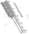
- reference numeral 1 generally indicates an exemplary embodiment of a beam member 1 of a frame system for a building structure.
- the beam member 1 comprises a parallel flange channel section comprising a web 2 bridging two parallel flanges 4, and an array of through-apertures or openings in the form of service openings or holes 6 spaced lengthwise along the web 2.
- the holes 6 are dimensioned so that, in use in the frame system, for example as a floor or roof assembly, wiring and pipework can be passed through the holes 6.
- the beam member 1 is open between the parallel flanges 4 to define a C-channel 8.
- reference numeral 10 generally indicates an exemplary embodiment of a spreader member or spreader 10.
- the spreader 10 comprises a parallel flange channel section comprising a web 12 bridging two parallel side flanges 14, and an array of through-apertures in the form of service openings or holes 16 spaced lengthwise along the web 12.
- the holes 16 are dimensioned so that, in use in a base or floor assembly, wiring and pipework can be passed through the holes 16.
- the spreader member 10 is shorter than the beam member 1.
- the spreader member 10 has a parallel end flanges 18 extending between or bridging the side flanges 14 at each terminal end 17 of the member 10.
- Opposed end portions 20 of the spreader 10 are sized to fit snugly between the parallel flanges 4 of the beam member 1.
- a width of the spreader 10 is reduced at the portions 20 so that the portions 20 can fit snugly between the parallel flanges 4 without the use of packing to take up any play.
- the width of the spreader 10 measured between the external sides of the parallel flanges 14 is substantially the same as the width of the channel 8 measured between facing sides of the parallel flanges 4.
- An extent of reduction of the spreader 10 at the portions 20 corresponds with twice the thickness of the material used for the beam member 1.
- external faces of the remaining portions of the spreader 10 are flush with external faces of the flanges 4.
- Further detail of the spreader 10 can be seen in figures 9 and 10 .
- a structure for example a floor made up of planar floorboards or members can be positioned on the spreader and beam members without the need for packing to take up any space between the floorboards or members and the spreader and beam members.
- the end flanges 18 also define portions 21 that are folded or bent inwardly to define inwardly extending zones or recesses that accommodate tabs 23 that extend from the side flanges and are folded over when the spreader is formed.
- the extent of the inward folding of the portions 21 is such that external faces of the tabs 23 are flush with an external surface of a remaining portion of the end flange 18.
- the length of the portions 20 is such that the flange 18 can butt or be brought to bear against the web 2.
- Both the spreader member 10 and the beam member 1 share the same sectional depth.
- end flanges 18 of the spreader member 10 enter the channel 8 of the beam member 1 between the flanges 4 of the beam member 1 to span the web 2 or to bridge or extend between the flanges 4.
- the web 12 of the spreader member 10 defines a plurality of openings 9. These can be used for fastening the beam members 1 to the spreaders 10 and for other purposes which are described below.
- reference numeral 30 generally indicates an example of a column member 30.
- the column member 30 is generally truncated-"A"-shaped in transverse cross section.
- the column member 30 comprises a pair of converging walls 32 converging at a flat strip or cap 33 interposed between the walls 32.
- Each of the walls 32 terminates at an edge from which there extends a foot or flange 34.
- the flanges 34 are substantially parallel with angled outturns 35 ( figure 83 ).
- the column member 30 has an array of bolt holes 31 in the cap 33, walls 32 and flanges 34. See for example figures 54 and 55 where these bolt holes are used.
- a building frame arrangement or system 62 ( figure 12 ) consists of three main elements, a 'C' formed member with open ends (i.e. the beam member 1), a 'C' formed member with integral cleats or closed ends (i.e. the spreader 10) and a substantially truncated 'A' formed member with open ends (i.e. the column member 30). All of these components can be formed from a sheet of steel fed from a roll of stock or coil. Alternatively, the components can be formed from sheet stock. For example, the components can use pre-sheeted steel coil or can be enabled to run from slit coil according to a required width of the respective component. Furthermore, widths of the material used for the components can either be the same or can vary with respect to each other depending on structural requirements.
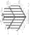
- reference numeral 50 generally indicates an exemplary embodiment of a frame assembly of the building frame system 62.
- the frame assembly 50 comprises pairs of beam members 1 arranged with webs 2 abutting in a back-to-back arrangement and end beam members 1 with webs 2 facing inwardly.
- the beam member 1 pairings are arranged into a spaced apart parallel array. Adjacent beam member pairings are bridged by an array of spaced apart parallel spreaders 10 to form a grid arrangement.
- the beam members 1 and spreaders 10 are bolted together via the bolt holes 9 provided in the beam member 1 and the spreader 10. At select locations of the frame assembly 50, the spreaders 10 are arranged into pairs with abutting webs 12 in a back-to-back arrangement.
- End flanges 18 of each spreader 10 fit into respective channels 8 of facing beam members 1 to butt or bear against the webs 12 of the beam members 1 as described above.
- the spreaders 10 are fixed to the beam members 1 by bolts that extend through the bolt holes in the webs 12 of the beam members 1 and the end flanges 18 of the spreader members 10.
- the spreaders 10 as well as the beam members 1 are placed back to back to form a double 'C' or 'I' shape in order to improve their load bearing capacity.
- the spreader 10 is one grid-length and the beam member is (but is not restricted to) four grid-lengths.
- a length of the column member 30, although not restricted, is set to comply with the most commonly available materials for panelling and walling. In every respect other than those already stated, the features (hole sets) for fasteners and general access holes within each grid of each member are substantially the same.
- the spreader member 10 to be positioned in a 'C' or double 'C' (or 'I' shape) arrangement along the length of the beam member 1 at regular repeating grid-length intervals and fixedly located with bolts or other methods as deemed suitable or appropriate.
- a floor assembly ground for a first floor of a building or dwelling includes a plurality of the frame assemblies 50 arranged side by side and bolted together.
- the floor assembly 60 sits on top of, and is bolted to a substrate such as a building foundation, footing or plinth 64.
- a plurality of equi-spaced column members 30 is bolted to a periphery of the floor assembly 60, and extends vertically upwards from the floor assembly 60.
- a plurality (in this case three) of the floor assemblies 60 are horizontally disposed and vertically spaced by a plurality of column members 30.
- a lowermost floor assembly 60.1 can support a ground floor of a building
- an intermediate floor assembly 60.2 can support a first floor of the building
- an uppermost floor assembly or roof frame assembly 60.3 can support a ceiling and/or a roof of the building.
- Figures 14 to 16 illustrate the formation of an external corner of a frame assembly 50 for a floor assembly 60 by bolting together a beam member 1 and a spreader member 10. Respective column members 30 are bolted through the holes 31 in the flanges 34 thereof to the beam member 1 and the spreader member 10 via a matching pattern of the holes in each.
- Figures 17 and 18 illustrate the formation of an internal corner of a frame assembly 50 for a floor assembly 60.
- Beam members 1 are bolted to spreader members 10.
- a column member 30 is bolted through flanges 34 thereof to one of the spreader members 10, via a matching pattern of holes in each.
- Figure 19 illustrates the formation of an internal corner of a frame assembly 50 for a floor assembly 60 by bolting together beam members 1 and spreader members 10. Column members 30 are then bolted through flanges 34 thereof to the beam member 1 and the spreader member 10 via a matching pattern of holes in each.
- Figures 20 and 21 illustrate the formation of an external edge of a frame assembly 50 for a floor assembly 60 by bolting together a beam member 1 and a spreader member 10. Column members 30 are then bolted through flanges 34 thereof to two spreader members 10 via a matching pattern of holes in each.
- Figure 19 further illustrates a cleat or gusset plate 40 stiffening an internal corner between a beam member 1 and a spreader member 10.
- the facility of the single or double 'C' arrangement for both spreader members 10 and beam members 1 allows any platform of any size to terminate at its perimeter with an inward facing 'C'. This in turn allows a column member 30 to be attached at or around the junction of any grid interval. It also permits a column member 30 to be placed anywhere within a platform that has or is provided with a single 'C' form for attachment.
- the commonality of the holes set out within the grids of the spreader members 10, beam members 1, and the column members 30, also provides the facility to fix grids at ninety degrees to each other as well as laterally and even vertically displace them to provide upper levels (such as upper floors and roof structures).
- the attributes common to the spreader member 10 and the beam member 1 mean that, however they are configured, they provide access for ducting to convey air from the air handler throughout the structure.
- Figures 22 to 45 show the steps of constructing a double story building structure 300 including three floor assemblies 60 and column members 30.
- Figure 22 shows a concrete footing 302 of the building structure 300.
- the footing 302 may include heated thermal masses 304, shown in figure 21 , for climate control of the building structure 300.
- the footing 302 also includes a passage formation 305 for the distribution of treated air from the thermal masses 304 throughout the structure 300.
- a number of frame assemblies 50 are assembled on the footing 302 to form a first floor assembly 60.1.
- the first floor assembly 60.1 may be bolted or otherwise fixed to the footing 302.
- Floor panels 310 are placed on top of the first floor assembly 60.1 to form a first floor 308 as shown in figure 25 .
- Four gaps or openings 312 are left in the floor 308 to provide access to jacks to rest directly on the footing 302 or to be bolted to the first floor assembly 60.1, as described below.
- a central gap or opening 314 is provided in the floor 308 for a staircase.
- Figure 26 shows the jacks 316 supported by the footing 302 and extending through the openings 312 in the first floor 308.
- the foot of each jack 316 rests on the footing 302 or is bolted to the first floor assembly 60.1.
- jacks for each floor level.
- any number of jacks could be used, depending on the area of each floor level. For example, in some cases three jacks could be used and in other cases more than four could be used.
- a number of frame assemblies 50 are assembled on the first floor 308 to form a second floor assembly 60.2.
- Floor panels 310 are placed on top of the second floor assembly 60.2 to form a second floor 320 as shown in figure 28 .
- Four gaps or openings 312 are left in the floor 320 to provide access for jacks 322 to be bolted to the second floor assembly 60.2.
- a central gap or opening 314 is provided in the floor 320 for the staircase ( figure 29 ).
- Figure 29 shows the jacks 322 fixed to the second floor assembly 60.2 and extending through the openings 312 in the second floor 320.
- the foot of each jack 322 is bolted or otherwise fixed to the second floor assembly 60.2.
- a number of frame assemblies 50 are assembled on the second floor 320 to form a third floor assembly 60.3.
- Figure 31 shows part of a roof framework 330 assembled using beam members 1 and spreader members 10 bolted together.
- the roof framework 330 is fixed to and supported by the roof frame assembly 60.3.
- Figure 32 shows the completed roof framework 330.
- Figure 33 shows the roof framework 330 with barge boards and gutters 332 fixed to the framework 330. Assembling the roof structure 330 is made easier and safer by the roof frame assembly 60.3 being close to the ground rather than in a conventional raised position.
- the roof structure 330 is covered by roof sheets 334 and solar panels 336 as shown in figures 34 and 35 . Once again, fixing the roof sheets 334 and solar panels 336 to the roof structure is made easier and safer by the roof structure 330 being close to the ground.
- Figure 38 shows the second floor assembly 60.2 and the roof frame assembly 60.3 partially raised relative to the first floor 308 by the jacks 316.
- the second floor assembly 60.2 is raised by the jacks to the position shown in figure 39 .
- Column members 30 are then fixed to the first floor assembly 60.1 and the second floor assembly 60.2 and extend between the floor assemblies 60.1, 60.2.
- the column members 30 are spaced along the periphery of the floor assemblies 60.1 and 60.2.
- the column members 30 support the second floor assembly 60.2 in the raised position shown in figure 40 .
- the roof frame assembly 60.3 is lifted or raised using the jacks 322.
- Figure 39 shows the roof frame assembly 60.3 partially raised relative to the second floor 320 by the jacks 322.
- the roof frame assembly 60.3 is raised to the position shown in figure 40 .
- Column members 30 are then fixed to the second floor assembly 60.2 and the roof frame assembly 60.3 to extend between the second floor assembly 60.2 and the roof frame assembly 60.3.
- the column members 30 support the roof frame assembly 60.3 in the raised position shown in figure 41 .
- the jacks 316, 322 can be removed.
- the first floor 308 and the second floor 320 can then be finished by placing floor panels in the openings 312 where the jacks 316, 322 stood.
- the building structure 300 is clad by cladding as shown in figure 43 .
- Window cavities are formed in the building structure and window frames inserted into the window cavities as shown in figure 44 .
- Figure 45 shows a partially sectioned view of the building structure.
- the holes 6, 16 in the beam members 1 and spreader members 10 provide paths for routing services such as wires, piping and ducting under the floors 308, 320 and in the roof.
- Figures 46 to 48 are illustrative of an example of a method for conveniently forming the floor assembly 60.1.
- a row of beam members 1 are connected together to span the footing 302.
- a row of the spreaders 10 is fastened on each side of the row of beam members 1. This initial assembly is formed towards one side of the footing 302.
- Remaining rows of beam members 1 and spreaders 10 are fastened to the other side of the footing 302 to form the floor assembly 60.1 as shown in figure 48 .
- the floor assembly 60 is built on the plinth or footing 64 without the need for cranes and other lifting equipment to move the floor assembly about.
- Figures 49 to 53 illustrate how the position of the columns 30 can be varied.
- a column 30 is fastened to a single spreader 10.
- two columns are fastened between two spreaders 10.
- the two spreaders 10 are transversely oriented relative to two other spreaders 10 positioned between paired beams 1.
- a column 30 is fastened to a spreader 10 at a junction between that spreader 10 and a pair of spreaders 10 connected between consecutive paired beams 1.
- a column 30 is fastened to a single spreader 10 extending between consecutive paired beams 1.
- a column 30 is fastened to a single spreader 10 extending between consecutive paired spreaders 10.
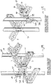
- Figures 54 and 55 show two different views of a manner in which a floor assembly 60 is fastened to consecutive columns 30 at a junction between two floors of a building or structure.
- the gusset plate 40 has a web 41 interposed between a pair of flanges 43.
- the flanges 43 and web 41 are oriented at about 45° relative to each other.
- a height or width of the plate 40 allows one of the flanges 43 to be fastened to the web 12 of the spreader 10 with fasteners 44 received through openings 45 in the flanges 43 and a corresponding set of openings 9 in the web 12.
- the opposed flange 43 is fastened to an internal surface of the web 2 of the beam 1 with the fasteners 44.
- the pair of spreaders 10 can thus be fastened to the internal surface of the beam 1 with two of the gusset plates 40.
- the end flange 18 of the spreaders 10 can also be fastened to the internal surface of the beam 1, as explained above.
- a lower column 30 is connected to an upper column 30 with splice members or plates 37.
- Each splice plate 37 has a profile that corresponds with a profile of one side of the column 30.
- the splice plate 37 has a faceplate 38 that can span adjacent upper and lower portions of consecutive columns 30.
- the faceplate 38 has a flange 39 that can span adjacent upper and lower portions of the flanges 34 of the consecutive columns 30.
- the faceplate 38 can be fastened or bolted to the converging walls 32 of the consecutive columns 30 via openings in the faceplate 38 and the bolt holes 31 in the columns 30.
- the flange 39 can be fastened or bolted to the flanges 34 of the consecutive columns 30.
- the openings in the flange 39, a corresponding set of holes 9 in the web 2 and the holes or openings in the flange 43 can be brought into register with each other allowing the splice plates 37, the columns 30, the beams 1 and the gusset plates 40 to be fastened together with a common set of the fasteners 44.
- Figures 56 to 58 show stages in the fastening of a floor assembly 62 column 30.
- figure 58 there is shown the use of a tool suitable for the fasteners 44.
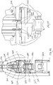
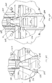
- Figures 59 to 62 show one of the jacks 316 (or the jacks 320) that can be used in the construction method or building system described herein.
- the jack 316 is telescopic having a lower section 340, an intermediate section 342 and an upper section 344, telescopically arranged with respect to each other.
- the sections have a square or rectangular cross-section, in plan. However, it is envisaged that other suitable sectional shapes are possible.
- a flange 346 is arranged on the lower section 340.
- the flange 346 can be bolted to faces of upper flanges 4 and upper flanges 14 of the beam members 1 and the spreader 10, respectively, of the lower or first floor assembly 60.1.
- a mounting head 348 is arranged on the upper section 344.
- the mounting head 348 also has a flange 350.
- the flange 350 can be bolted to faces of lower flanges 4 and lower flanges 14 of the beam members 1 and the spreader 10, respectively.
- Keeper members or keepers 352 are arranged on the mounting head 348. Each keeper 352 has a locating formation or foot 354 that is positioned so that a further floor assembly 60 can be constructed or positioned between the foot or feet 354 and the preceding floor assembly 60.
- the further floor assembly 60 such as the second floor assembly 60.2, can be jacked upwardly while being secured between the flange 350 and the keepers 352.
- keepers 352 can have a variety of configurations that serve the purpose of securing the further floor assembly 60 against excessive movement relative to the mounting head 348 while being jacked upwardly.
- the intermediate section 342 and the upper section 344 have sets of support pins or pegs 356 at the respective lower ends.
- the pegs 356 of each section are configured to project from walls 358 and to rest on upper ends of a preceding section once that section is extended.
- the pegs 356 can thus serve to support the jack 316 as it is extended in various stages.
- the jack 316 is hydraulic or pneumatic.
- the pegs 356 serve to avoid the need for having fluid pressure support the jack 316 in its extended or partially extended condition.
- the pegs 356 can be spring mounted to extend automatically. Alternatively, the pegs 356 can be manually or remotely operated.
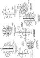
- Figure 63 shows a forming machine 100, not forming part of the claimed subject-matter, for forming a blank of material into the spreader member 10.
- the forming machine 100 is configured for carrying out reciprocal forming and shaping operations on metal sheeting to form the spreader 10.
- the forming machine 100 is suited for cutting, stamping and/or punching and pressing and/or folding lengths of steel stockfeed to form the spreader members 10.
- the forming machine 100 comprises a base 102 supporting a bottom die 104, and columns 106 extending vertically from the base 102 and spaced around the bottom die 104.
- the columns 106 support a platform 108 in a suspended position above the bottom die 104.
- Two top die actuators 110 are mounted on the platform 108.
- the actuators 110 drive a top die 112 between a home position and a forming position.
- the top die 112 is in its home position sufficient space is provided between the top and bottom dies 112 and 104 to feed a blank 10A between the dies.
- the top and bottom dies 112 and 104 cooperatively carry out a forming operation.
- the machine 100 has a two parallel side flange formers 114 (hereinafter referred to as flippers 114) for forming the parallel flanges 14 of the spreader member 10.
- the flippers 114 are located at either side of the bottom die 104.
- the horizontal and vertical flipper actuators 116 and 118 act cooperatively to move the flippers 114 between a home position and a forming position.
- Figure 78 shows a machine 150 for forming the beam member 1.
- the machine 150 is configured for carrying out reciprocal forming and shaping operations on metal sheet to form the beam members 1.
- the machine 150 only requires the above described formers and former actuators. Operation of the machine 150 may be at least partially automated by use of a programmable logic controller (PLC) running a program such as that represented in the flow chart of Figure 79 .
- PLC programmable logic controller
- the machine 100 for forming the spreader 10 requires all of the above described formers 114 and former actuators 110, plus the additional parts described below with reference to Figures 63 to 77 .
- plungers 120 Two end flange formers 120 (hereinafter referred to as plungers 120) are mounted on the platform 108, with one plunger 120 at each end of the die 104.
- plunger actuators 122 and 124 for driving the plungers 120 between a home position and a forming position, and a plunger actuator 126 for returning the plunger 120 to its home position.
- the base 102 further supports four tail arms 130 (the function of which will be explained below), two for each end of the die.
- the base 102 further supports two end punches 140, one for each end of the die, for punching holes in the end flanges 18.
- end punch actuator 142 for driving the end punches 140 between a home position and a punching position.
- operation of the forming machine 100 for forming spreader members 10 may be at least partially automated by use of a programmable logic controller (PLC) running a program such as that represented in the flow chart of Figure 80 .
- PLC programmable logic controller
- a blank 10A is fed between the top and bottom dies 112 and 104. Where feeding of the blank 10A is automated, sensors may be employed to sense the presence of the blank 10A and commence operation of the machine 100. Where feeding of the blank 10A is performed manually, commencement of operation will likely be contingent upon the closing of a guard (not illustrated).
- Operation of the machine 100 commences with the closure of the top die 112 onto the bottom die 104, as illustrated in figure 65 .
- This forms the holes 9 and 16, and other features on the web 12 of the spreader 10.
- This also forms the cuts or notches that are required for carrying out the necessary folding or bending operations to achieve the spreader 10.
- the flanges 14, 18 and the tabs 28 are in the pre-bent or pre-folded conditions subsequent to operation of the closure of the top die 112 onto the bottom die 104.
- the flippers 114 are then moved from their home positions to their forming positions, forming the parallel flanges 14.
- the plungers 120 are actuated to fold the end flanges 18 in a similar process, and then the plungers 120 are returned to their home positions. Then the tail arms 130 are actuated, each tail arm 130 folding one tab 20 over the end flange 18. Each tail arm 130 is then returned to its home position.
- the operation that is carried out to form the end flanges 18 is similar to that that is carried out to form the flanges 14. It follows that the plungers 120 incorporate a tool or die former 120A that is similar to the tools 114 A. For example, the actuator 122 drives the downward or vertical movement of the tool 120A while the actuator 124 drives the horizontal movement of the tool 120A.
- the end punches 140 are actuated to punch bolt holes in the end flanges 18 and are then returned to their home positions.
- the top die 112 is returned to its home position, and then the flippers 114 are returned to their home positions. In this way, the flippers prevent the part (i.e. spreader member 10) being raised with the top die 112.
- the forming machine 100 performs a number of sequential functions in close order.
- the forming machine 10 could be mounted to a truck bed or tray, or to a trailer for towing behind a vehicle. In this way, spreader members 10 could be formed at a building site.
- the forming machine 100 could also be used to form the beam members 1, by switching the PLC to run a program such as that represented in the flow chart of Figure 79 , and by feeding a blank (a longer blank than blank 10A - not illustrated) lengthwise into the machine 100 in stages (and with a high degree of accuracy), so that a portion of the beam member 1 profile is formed at a time.
- the forming machine 150 not forming part of the claimed subject-matter, of figure 78 is configured specifically for forming beam members 1.
- the forming machine 150 comprises longer top and bottom dies 112 and 104, and flippers 114 than the forming machine 100. However, the machine 150 does not include the plungers 120, tail arms 130 or end punches 140 of the forming machine 100.
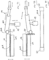
- Figures 81 to 83 show views of the column member 30.
- the column member 30 comprises a truncated "A" form section comprising sloping walls 32 which depend and diverge from a flat strip or cap 33.
- the column member 30 includes substantially parallel flanges 34 with angled outturns 35 and arrays of holes 31 in the cap 33, the walls 32 and the flanges 34.
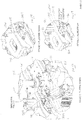
- FIG. 84 and 85 there is shown a forming machine 200, not forming part of the claimed subject-matter, for forming a blank of material into the column member 30.
- the forming machine 200 comprises a material magazine 202 and a forming section 204.
- the forming section 204 comprises four spaced journals 206 mounted on a number of through beams, so as to feed material into the forming section 204.
- the magazine 202 butts directly onto the forming section 204 and forms a structural part of the whole base frame of the machine 200.
- a punching station 203 is positioned at a feed end of the forming section 204 and is operable to punch openings or holes into stock to form the holes 31 of the column member 30.
- the journals 206 support two outer fixed dies 208 that complete the outturns 35 on the completed "truncated - A" form.
- the journals 206 also support and house an upper die support beam 209.
- the upper die support beam 209 is aligned and supported by control elements 210 within the journals and rests on control stops 212 at each end of the machine.
- the support beam 209 is able to move upwards under the control of an actuator 214 placed in the head of each of the four journals 206.
- the actuators 214 allow for the controlled vertical movement of the upper die support beam 209.
- Within the support beam 209 is a longitudinal space 216 that houses an upper die 220.
- the die 220 is of a semi resilient material.
- a lower beam 221 is supported by side control elements 222 where it passes through each journal and in turn rests on upward facing actuators 224.
- the lower beam 221 is comprised of an inner and outer members.
- the inner member is moveably supported within the outer member on a number of actuators 230.
- the inner member supports a lower die 234 which, together with the upper die 220, determines the angle of the truncated "A" form.
- the lower inner and outer members of the lower beam form the column member 30 as described below.
- the upper die 220 is constrained to its bottom home position, providing a material thickness between itself and the bottom die 234.
- the lower die actuators 224 drive the lower die 234 upwards into the resilient upper die 220 to form the bends at the lateral edges of the cap 33 of the column member 30.
- the constraint of the upper die 220 is then relaxed and the upper and lower dies 220, 234 move down together until a lower outer die 235 closes onto the upper outer fixed die 208, so completing the second bend of the "A" form, forming the flanges 34.
- Lower die inner actuators 230 are now enabled to collapse which allows the outer lower dies 232 to close onto the upper fixed dies 208 to form the outturns 35 along each side of the "A" form.
- Operation of a forming machine 200 for forming column members 30 may be at least partially automated by use of a programmable logic controller (PLC) running a program.
- PLC programmable logic controller
- a blank 1A is fed between the top and bottom dies 208 and 234. Where feeding of the blank 1A is automated, sensors may be employed to sense the presence of the blank 1A and commence operation of the machine 200. Where feeding of the blank 1A is performed manually, commencement of operation will likely be contingent upon the closing of a guard (not illustrated).
- the punching station 203 pre-forms the bolt holes in sheet 1A in stages as it passes from the magazine 204 into the "A" forming part of the machine 202 of the machine. This will result in the forming of the many holes 31, and other features on the web 33 of the part 30.
- the punching station 203 has a housing 227.
- the housing 227 defines an entry wall 229 and an exit wall 231. Both walls 229, 231 have openings 232 to permit the passage of the blank 1 A.
- a bed 237 is mounted on a suitable support structure in the housing 203 for supporting the blank 1 A.
- a punching head 239 is mounted in the housing to be vertically reciprocally displaceable with respect to the bed 237.
- a series of punching dies 241 mounted on the head so that when the head 237 is driven reciprocally, the punching dies 241 can carry out a punching operation on the blank 1 A to form the holes 31 in the blank.
- a pair of actuators 243 also mounted on the housing to drive the head 237.
- the forming machine 200 performs a number of sequential functions in close order, but for reasons of distribution and portability the desired machine is as small and compact as possible.
- the forming machine 200 could be mounted to a truck bed or tray, or to a trailer for towing behind a vehicle. In this way, column members 30 could be formed at a building site.
- actuators referenced herein could be hydraulic cylinders. However, in cases where alternate actuator types (such as electric or pneumatic actuators) can deliver the required force to perform the relevant operation, then these may be employed.
- the flanges 14 of the spreader 10 are bent or formed so that the portions 20 can be received between the flanges 4 of the beam members 1 without the need for packing or washers.
- the flanges 14 are formed so that an overall width of the portion 20 is reduced by an extent which is twice the width of the material used for the associated beam 1.
- flanges 18 of the spreader 10 are bent or formed to accommodate the tab 23 such that the flanges 18 present a flat surface for hearing or butting against the web 2 of the beam members 1.
- Figures 95 to 99 indicate a principle of operation that is employed to generate or form the flanges 14, 18.
- like reference numerals refer to like parts, unless otherwise specified.
- the use of the common numerals is not intended to indicate that the parts or components referred to in the preceding drawings are somehow essential to the structures shown in figures 90 to 94 .
- the flipper 114 is mounted on the horizontal flipper actuator 116 with a spherical steel bearing 115. This facilitates pivotal movement of an arm 117 of the flipper 114.
- the vertical movement of the flipper actuator 118 is operated with a draw ram 119.
- the flipper 114 is shown in in an up position prior to a drawing process to be performed on the blank. In figure 91 , the flipper 114 is in a down position subsequent to the drawing process.
- the tool 114A acts on the blank to form the flange 14. This process is indicated schematically in figures 92 and 93 .
- the setback of the bottom die 104 relative to the upper die 102 can be seen in these drawings.
- the tool 114A has enlarged end portions 121. A length of these end portions 121 corresponds generally with a length of the portions 20 of reduced width of the spreaders 10. It follows that operation of the flippers 114 results in fold lines 123, 125 of the spreader 10 ( figures 9, 10 ).
- the tool 114A does not rotate relative to the flipper body 127. Thus, the tool 114A carries out a drawing process on the blank to form the associated flange 14.
- the draw ram 119 provides the necessary pivotal movement of the tool 114A in a vertical plane.
- the horizontal flipper actuator 116 provides the necessary horizontal movement of the tool 114A to generate sufficient horizontal force such that the fold lines 123, 125 are formed in the drawing process.
- the flanges 18 are formed in a similar manner using the plungers 120 and the actuators 122, 124 and 126, all of which drive the tools 120A in the same way as the tool 114A is driven.
- fold lines 129, 131 are formed in the flange 18 ( figures 9, 10 ) to accommodate the tabs 23 so that the tabs 23 and the flange 18 present a flat surface for abutment against an inner surface of the web 2.
- the forming machines are conveyed to an area in which building structures are to be erected using the frame assemblies described above.
- the forming machines can be used on site to fabricate the components required for the frame assemblies.
- the various components, particularly the beam and spreader members are modular in nature. It follows that they can be connected together using a common bolt and nut combination.
- a typical example of such a bolt and nut combination would be one in which a head and a nut both incorporate a flange such that the parts of the components can be sandwiched between the flanges.
- the components are assembled without the need for washers or flanges. It follows that it is not necessary to use washers with the bolt and nut combinations.
- the forming machines can be configured to function in a range of conditions, such as in solar-powered container-based arrangements or, where possible, in a traditional factory arrangement.
- the possibility of using the forming machines in shipping containers enhances the ability to transport the shipping machines to locations where the building method described herein can be practised or carried out.
- a suitable thickness may be anywhere between 1 mm and 8 mm, for example, between about 1 mm and 6 mm.
- the dimensions of the beams 1 and spreaders 10 can vary depending on the required application and various structural requirements.
- the spreader and beam members can be fabricated by forming machines with a power output of about 3 hp. This results in components being fabricated at about 1 to 2 minutes per part. At that rate, the inventor envisages that all the spreader and beam members required for the first floor of the structure of the building described above could be provided within five hours. As result, it is expected that an entire frame for the building described above could be erected within 3 to 4 days.
- a method of building would include transporting forming machines to a building site, forming a strip of steel into the various components required for the base assembly and erecting a building or structure using a number of the base assemblies.
Landscapes
- Engineering & Computer Science (AREA)
- Architecture (AREA)
- Civil Engineering (AREA)
- Structural Engineering (AREA)
- Physics & Mathematics (AREA)
- Electromagnetism (AREA)
- Mechanical Engineering (AREA)
- Conveying And Assembling Of Building Elements In Situ (AREA)
- Joining Of Building Structures In Genera (AREA)
Claims (15)
- Système de charpente (50) pour une structure de construction, le système comprenant :des éléments de poutre (1), chaque élément de poutre (1) comprenant :deux brides parallèles opposées (4) ; etune âme (2) interposée entre les brides (4) ; etdes éléments d'écartement (10), chaque élément d'écartement (10) comprenant :deux brides latérales parallèles opposées (14) ;une âme (12) interposée entre les brides latérales (14) ; etdeux brides d'extrémité (18) opposées au niveau des extrémités respectives de l'âme,dans lequel les éléments de poutre (1) et les éléments d'écartement (10) sont conçus pour être fixés les uns aux autres de manière à former un ensemble de charpente, dans lequelau moins une partie d'extrémité (20) de chaque élément d'écartement (10) présente une longueur qui est supérieure à une profondeur des brides (4) des éléments de poutre (1) et présente une largeur réduite de manière à permettre à la partie d'extrémité (20) de s'adapter et de s'étendre entre les brides (4) des éléments de poutre (1), les brides (4) des éléments de poutre (1) et les brides latérales (14) des éléments d'écartement (10) étant sensiblement coplanaires de telle sorte que le système de charpente peut fournir une surface de support plane ; etcaractérisé en ce que les brides d'extrémité (18) de chaque élément d'écartement (10) définissent des parties (21) qui sont pliées vers l'intérieur pour définir des zones (21) s'étendant vers l'intérieur qui reçoivent des languettes (23) s'étendant à partir des brides latérales (14), de telle sorte que les faces externes des languettes (23) sont au même niveau qu'une surface externe d'une partie restante de la bride d'extrémité (18), les brides d'extrémité (18) et les languettes (23) présentant une surface sensiblement plane de telle sorte que les brides d'extrémité (18) peuvent être fixées directement aux âmes (2) des éléments de poutre (1) sans utiliser de rondelles ou de garniture.
- Système de charpente (50) selon la revendication 1, dans lequel l'au moins une partie d'extrémité (20) présente une largeur réduite dans une mesure qui est sensiblement équivalente à deux fois l'épaisseur d'un matériau des éléments de poutre (1).
- Système de charpente selon la revendication 1, dans lequel les brides latérales (14) de l'élément d'écartement (10) sont formées pour définir l'au moins une partie d'extrémité (20).
- Système de charpente selon la revendication 1, dans lequel les âmes (2) des éléments de poutre et d'écartement (1), (10) définissent des ouvertures (6), (16) pour recevoir des services de construction.
- Système de charpente (50) selon la revendication 1, qui comprend des paires d'éléments de poutre (1) disposés avec des âmes en butée (2), dans lequel les paires de poutres sont disposées en un réseau parallèle espacé, et dans lequel des paires de poutres adjacentes sont reliées par un réseau d'éléments d'écartement parallèles espacés (10) .
- Système de charpente (50) selon la revendication 5, dans lequel les éléments d'écartement (10) comprennent au moins une paire d'éléments d'écartement (10) disposés avec des âmes en butée (12).
- Procédé de construction, qui comprend la fixation de la poutre (1) et des éléments d'écartement (10) selon la revendication 1 ensemble pour former le système de charpente (50) selon l'une quelconque des revendications précédentes.
- Procédé selon la revendication 7, qui comprend :le formage de deux ou plusieurs systèmes de charpentes (50) sur un substrat, l'un au-dessus de l'autre, de telle sorte qu'un système de charpente inférieur définit un ensemble de rez-de-chaussée (60.1) et un système de charpente supérieur définit un ensemble de toit (60.3) ;l'installation d'une structure de toit sur le système de charpente supérieur alors que le système de charpente supérieur reste sur l'un parmi l'ensemble de rez-de-chaussée (60.1) et un ensemble de plancher intermédiaire (60.2) ; etle levage au moins du système de charpente supérieur pour définir au moins un niveau de plancher de la structure du construction (300).
- Procédé selon la revendication 8, qui comprend le formage des éléments de poutre et d'écartement (1), (10) en effectuant des opérations réciproques de formage et de façonnage sur plaque métallique.
- Procédé selon la revendication 9, dans lequel chaque élément d'écartement (10) est formé en effectuant les opérations suivantes sur une longueur de plaque métallique :le poinçonnage de la plaque pour former des ouvertures et des encoches ou des coupures dans la plaque ;le pliage des côtés de la plaque pour former des brides latérales (14) ;le pliage des extrémités de la plaque pour former des brides d'extrémité (18) opposées ; etle pliage des languettes (23) s'étendant des brides latérales (14) sur les brides d'extrémité (18).
- Procédé selon la revendication 10, dans lequel l'étape de pliage des côtés de la plaque est effectuée de telle sorte qu'au moins une partie d'extrémité (20) de l'élément d'écartement (10) résultant présente une longueur qui est supérieure à une profondeur des brides (4) des éléments de poutre (1) et présente une largeur réduite de façon à permettre à la partie d'extrémité (20) de s'adapter et de s'étendre entre les brides (4) des éléments de poutre (1).
- Procédé selon la revendication 11, dans lequel l'étape de pliage des côtés de la plaque est effectuée de telle sorte qu'au moins une partie d'extrémité (20) peut s'adapter entre les brides (4) des éléments de poutre (1), les brides des éléments de poutre et les éléments d'écartement (4), (14) étant sensiblement coplanaires.
- Procédé selon la revendication 10, dans lequel les opérations réciproques de formage et de façonnage sont effectuées par une machine de formage qui est située dans un chantier de construction sur lequel la structure de construction doit être construite.
- Structure de construction (300), qui comprend :
au moins deux systèmes de charpentes (50) selon la revendication 1. - Structure de construction (300) selon la revendication 14, dans laquelle un des systèmes de charpente (50) est un ensemble de rez-de-chaussée (60.1) supporté sur une base et un autre des systèmes de charpente (50) est un ensemble de toit (60.3) supporté au-dessus de l'ensemble de rez-de-chaussée (60.1), de telle sorte qu'au moins un niveau de plancher (60.2) est défini entre l'ensemble de rez-de-chaussée (60.1) et l'ensemble de toit (60.3).
Applications Claiming Priority (3)
| Application Number | Priority Date | Filing Date | Title |
|---|---|---|---|
| AU2014902604A AU2014902604A0 (en) | 2014-07-07 | Building framing improvements | |
| AU2014902687A AU2014902687A0 (en) | 2014-07-11 | A forming machine for forming a building frame member | |
| PCT/AU2015/050381 WO2016004474A1 (fr) | 2014-07-07 | 2015-07-07 | Systèmes de charpente pour structures de construction |
Publications (3)
| Publication Number | Publication Date |
|---|---|
| EP3186455A1 EP3186455A1 (fr) | 2017-07-05 |
| EP3186455A4 EP3186455A4 (fr) | 2018-03-14 |
| EP3186455B1 true EP3186455B1 (fr) | 2020-11-04 |
Family
ID=55063400
Family Applications (1)
| Application Number | Title | Priority Date | Filing Date |
|---|---|---|---|
| EP15819176.7A Active EP3186455B1 (fr) | 2014-07-07 | 2015-07-07 | Systèmes de charpente pour structures de construction |
Country Status (5)
| Country | Link |
|---|---|
| US (2) | US10151100B2 (fr) |
| EP (1) | EP3186455B1 (fr) |
| CN (2) | CN111877625B (fr) |
| AU (2) | AU2015286222B2 (fr) |
| WO (1) | WO2016004474A1 (fr) |
Families Citing this family (8)
| Publication number | Priority date | Publication date | Assignee | Title |
|---|---|---|---|---|
| LT6370B (lt) * | 2015-06-10 | 2017-03-10 | Uab Aldrea | Sijos komponentai, skirti techniniam konstravimui, konstravimo rinkinys ir sijos komponentų sujungimo būdas |
| US20180050381A1 (en) * | 2016-06-21 | 2018-02-22 | Seoul Laser Dieboard System Co., Ltd. | Preparing holes on rules or profiles used for channel letters |
| DE102016221111A1 (de) * | 2016-10-26 | 2018-04-26 | Airbus Operations Gmbh | Kabinenmonument für ein Luftfahrzeug |
| US10006193B1 (en) * | 2017-02-07 | 2018-06-26 | Tai Yu Liu | Lightweight steel construction |
| US10316509B2 (en) * | 2017-04-03 | 2019-06-11 | Revamp Panels, LLC | Post and beam system |
| US10202149B1 (en) * | 2017-08-11 | 2019-02-12 | Super ATV, LLC | ATV/UTV skid plate assembly |
| CN108729543A (zh) * | 2018-07-31 | 2018-11-02 | 巩俊贤 | 一种建筑用的安装组件及其建筑物 |
| CN117282899B (zh) * | 2023-11-27 | 2024-02-02 | 山西恒冠重工集团有限公司 | 一种法兰加工用锻压装置 |
Family Cites Families (40)
| Publication number | Priority date | Publication date | Assignee | Title |
|---|---|---|---|---|
| US1780433A (en) * | 1928-03-07 | 1930-11-04 | James A Mcgregor | Die for flanging sheet metal |
| US1821151A (en) * | 1929-05-16 | 1931-09-01 | Union Metal Prod Co | Car construction |
| US2476595A (en) * | 1945-02-22 | 1949-07-19 | Lee B Green | Expansible die punch for bending flanged work with tangent bending apparatus |
| US2536643A (en) * | 1948-01-15 | 1951-01-02 | Michigan Bumper Corp | Reciprocating dies with pivoted and slidable end shaping dies |
| US2966873A (en) * | 1955-01-11 | 1961-01-03 | Lockheed Aircraft Corp | Device for forming sheet material |
| US2821233A (en) * | 1955-01-25 | 1958-01-28 | Western Electric Co | Safety edge forming apparatus |
| US3243930A (en) * | 1962-05-29 | 1966-04-05 | Nat Gypsum Co | Corrugated sheet metal structural members |
| US3367009A (en) * | 1965-09-07 | 1968-02-06 | Smith Corp A O | Method of forming an elongated channel member |
| US3751870A (en) | 1971-02-05 | 1973-08-14 | Elkhart Wlding & Boiler Works | Frame structure system |
| GB1468190A (en) * | 1973-11-30 | 1977-03-23 | Ekert D | Metal frame member |
| FR2523483B1 (fr) * | 1982-03-19 | 1985-09-27 | Pauzin Alexis | Outil de pliage a plat |
| DE3672921D1 (de) * | 1985-01-25 | 1990-08-30 | Per Wiklund | Plattenprofil. |
| JP2853123B2 (ja) * | 1986-03-12 | 1999-02-03 | ドン インコ−ポレイテッド | 常温圧延金属成形物及びその成形方法並びにその成形装置 |
| US4875274A (en) * | 1987-03-26 | 1989-10-24 | Foster Larry L | Method of cutting metal stud and bending and securing same to form angel member |
| AU602119B2 (en) * | 1987-08-13 | 1990-09-27 | El Barador Holdings Pty Ltd | Structural assemblies |
| AU622263B2 (en) * | 1989-01-19 | 1992-04-02 | Roofing Centre Albury/Wodonga Pty. Ltd., The | Structural framing |
| AU640566B2 (en) * | 1991-08-07 | 1993-08-26 | Force 10 International Pty Ltd | Jointing of structural members |
| US5271256A (en) * | 1992-08-27 | 1993-12-21 | The Whitaker Corporation | Tooling module for stamping and forming machine |
| AU720746B2 (en) * | 1995-12-06 | 2000-06-08 | Dalmain Frederick Untiedt | Building structure |
| CA2293322A1 (fr) * | 1997-06-11 | 1998-12-17 | Cds Nu-Steel Pty. Ltd. | Systeme de cadre pour batiments |
| US6301854B1 (en) | 1998-11-25 | 2001-10-16 | Dietrich Industries, Inc. | Floor joist and support system therefor |
| WO2001090498A1 (fr) * | 2000-05-25 | 2001-11-29 | Nippon Steel Corporation | Structure de joint pour construction comprenant des plaques d'acier de faible epaisseur |
| US20040144057A1 (en) * | 2003-01-27 | 2004-07-29 | Allied Tube & Conduit Corporation | Framing system for buildings |
| US7765771B2 (en) * | 2004-10-08 | 2010-08-03 | Ware Industries, Inc. | Structural framing system and components thereof |
| US20060150548A1 (en) * | 2004-12-27 | 2006-07-13 | Gcg Holdings Ltd | Floor system with stell joists having openings with edge reinforcements and method |
| NZ545483A (en) * | 2005-02-23 | 2006-11-30 | Weeks Peacock Quality Homes | Method of connecting floor joist to bearer in floor frame |
| AU2006200728B2 (en) * | 2005-02-23 | 2010-12-09 | Steel Building Systems Australia Pty Ltd | Method of connecting floor joist to bearer in floor frame |
| US7677071B2 (en) * | 2006-06-02 | 2010-03-16 | Bh Legacy, Llc | Apparatus for the fabrication of metal wall frame members and assembly of wall frames therefrom, and foldable wall frame structures |
| JP2010502445A (ja) * | 2006-08-28 | 2010-01-28 | インダストリアル オリガミ インコーポレイテッド | 複合折り目線をシート材料に形成するための方法及び装置 |
| JP4347375B2 (ja) * | 2007-09-03 | 2009-10-21 | シャープ株式会社 | 太陽電池モジュール |
| CA2643248A1 (fr) * | 2008-11-05 | 2010-05-05 | Gcg Holdings Ltd | Appareil et procede de faconnage de tole en bandes multifonctions |
| CN201404989Y (zh) * | 2009-02-09 | 2010-02-17 | 张艳辉 | 下料冲孔可同时完成的槽钢冲压模具 |
| US8688411B2 (en) * | 2009-12-18 | 2014-04-01 | John Louis Vanker | Method and system of using standardized structural components |
| JP2011218436A (ja) * | 2010-04-14 | 2011-11-04 | Honda Motor Co Ltd | 熱間プレス成形方法 |
| US9834940B2 (en) * | 2010-05-06 | 2017-12-05 | 9344-8462 Québec Inc. | Modular building structures improvements |
| JP5808297B2 (ja) * | 2012-06-27 | 2015-11-10 | Jfeスチール株式会社 | プレス成形方法、プレス成形装置 |
| WO2014053004A1 (fr) * | 2012-10-02 | 2014-04-10 | Csr Building Products Limited | Raccord |
| FR3003283B1 (fr) * | 2013-03-12 | 2021-03-19 | Sas Dhomino | Systeme de construction modulaire |
| TWM491702U (zh) * | 2014-05-09 | 2014-12-11 | Sucoot Ind Co Ltd | 建築用之樑體 |
| US9890533B2 (en) * | 2015-09-22 | 2018-02-13 | Lakdas Nanayakkara | Metal stud frame element |
-
2015
- 2015-07-07 US US15/324,725 patent/US10151100B2/en active Active
- 2015-07-07 EP EP15819176.7A patent/EP3186455B1/fr active Active
- 2015-07-07 CN CN202010583133.1A patent/CN111877625B/zh active Active
- 2015-07-07 CN CN201580044748.4A patent/CN107075856B/zh active Active
- 2015-07-07 WO PCT/AU2015/050381 patent/WO2016004474A1/fr active Application Filing
- 2015-07-07 AU AU2015286222A patent/AU2015286222B2/en active Active
-
2018
- 2018-11-05 US US16/180,833 patent/US10895072B2/en active Active
-
2019
- 2019-07-17 AU AU2019206026A patent/AU2019206026B2/en active Active
Non-Patent Citations (1)
| Title |
|---|
| None * |
Also Published As
| Publication number | Publication date |
|---|---|
| AU2019206026B2 (en) | 2021-03-11 |
| US20190078312A1 (en) | 2019-03-14 |
| CN107075856B (zh) | 2020-07-17 |
| AU2019206026A1 (en) | 2019-08-01 |
| EP3186455A4 (fr) | 2018-03-14 |
| EP3186455A1 (fr) | 2017-07-05 |
| AU2015286222A1 (en) | 2017-03-02 |
| WO2016004474A1 (fr) | 2016-01-14 |
| CN111877625B (zh) | 2023-01-03 |
| US20170204597A1 (en) | 2017-07-20 |
| CN111877625A (zh) | 2020-11-03 |
| AU2015286222B2 (en) | 2019-08-29 |
| US10151100B2 (en) | 2018-12-11 |
| US10895072B2 (en) | 2021-01-19 |
| CN107075856A (zh) | 2017-08-18 |
Similar Documents
| Publication | Publication Date | Title |
|---|---|---|
| US10895072B2 (en) | Frame systems for building structures | |
| US20130047539A1 (en) | Building Structure | |
| EP2812505B1 (fr) | Système de construction modulaire | |
| US11028575B2 (en) | Method and system for collapsible wall frame with spacers that pre-determine placement of structural components | |
| CN113795438A (zh) | 储存系统 | |
| JP4441406B2 (ja) | モジュラー建築ユニットの垂直整列および水平化 | |
| JP5834376B1 (ja) | 木質ラーメン構造体の施工方法 | |
| EP3418460A1 (fr) | Unité préfabriquée | |
| US9163396B1 (en) | Modular building system | |
| CN103827410B (zh) | 砌体建筑物及砌体建筑物的构筑方法 | |
| CN113247651B (zh) | 一种带皮带机栈桥的门式刚架仓储结构的制作方法 | |
| JP6429239B2 (ja) | 木質ラーメン構造体、及びその木質ラーメン構造体の補強金具 | |
| WO2011056897A2 (fr) | Système de bâtiment et procédé | |
| JP2008214932A (ja) | 建物の構築方法 | |
| KR102300810B1 (ko) | 구조물 인상장치 및 그 장치를 이용한 구조물 인상방법 | |
| JP7193258B2 (ja) | 建物及び床の施工方法 | |
| AU2009235958B2 (en) | Prefabricated building | |
| KR100276864B1 (ko) | 거푸집용 코너 바 및 이를 이용한 거푸집 설치 방법 | |
| JP2656390B2 (ja) | ユニット住宅 | |
| DE202006003776U1 (de) | Druckkammer | |
| JPH04155034A (ja) | 小規模建築物の施工方法 | |
| JP2003253764A (ja) | 建物ユニット | |
| JPH09510517A (ja) | シート状金属材料にて集成された前荷重処理した標準化壁部材 | |
| JP2008215012A (ja) | 建物の構築方法 | |
| JP2008215013A (ja) | 建物の構築方法 |
Legal Events
| Date | Code | Title | Description |
|---|---|---|---|
| STAA | Information on the status of an ep patent application or granted ep patent |
Free format text: STATUS: THE INTERNATIONAL PUBLICATION HAS BEEN MADE |
|
| PUAI | Public reference made under article 153(3) epc to a published international application that has entered the european phase |
Free format text: ORIGINAL CODE: 0009012 |
|
| STAA | Information on the status of an ep patent application or granted ep patent |
Free format text: STATUS: REQUEST FOR EXAMINATION WAS MADE |
|
| 17P | Request for examination filed |
Effective date: 20170207 |
|
| AK | Designated contracting states |
Kind code of ref document: A1 Designated state(s): AL AT BE BG CH CY CZ DE DK EE ES FI FR GB GR HR HU IE IS IT LI LT LU LV MC MK MT NL NO PL PT RO RS SE SI SK SM TR |
|
| AX | Request for extension of the european patent |
Extension state: BA ME |
|
| DAV | Request for validation of the european patent (deleted) | ||
| DAX | Request for extension of the european patent (deleted) | ||
| RIN1 | Information on inventor provided before grant (corrected) |
Inventor name: MCDONALD, DOUGLAS ARTHUR |
|
| A4 | Supplementary search report drawn up and despatched |
Effective date: 20180213 |
|
| RIC1 | Information provided on ipc code assigned before grant |
Ipc: B21D 5/00 20060101ALI20180207BHEP Ipc: E04B 1/19 20060101ALI20180207BHEP Ipc: B21D 22/00 20060101ALI20180207BHEP Ipc: E04B 5/10 20060101AFI20180207BHEP Ipc: E04B 5/14 20060101ALI20180207BHEP Ipc: B21D 28/00 20060101ALI20180207BHEP Ipc: B21D 11/00 20060101ALI20180207BHEP Ipc: B21D 19/00 20060101ALI20180207BHEP Ipc: E04B 1/24 20060101ALI20180207BHEP Ipc: E04B 1/08 20060101ALI20180207BHEP Ipc: B21D 37/00 20060101ALI20180207BHEP |
|
| STAA | Information on the status of an ep patent application or granted ep patent |
Free format text: STATUS: EXAMINATION IS IN PROGRESS |
|
| 17Q | First examination report despatched |
Effective date: 20190621 |
|
| GRAP | Despatch of communication of intention to grant a patent |
Free format text: ORIGINAL CODE: EPIDOSNIGR1 |
|
| STAA | Information on the status of an ep patent application or granted ep patent |
Free format text: STATUS: GRANT OF PATENT IS INTENDED |
|
| INTG | Intention to grant announced |
Effective date: 20200327 |
|
| GRAS | Grant fee paid |
Free format text: ORIGINAL CODE: EPIDOSNIGR3 |
|
| GRAJ | Information related to disapproval of communication of intention to grant by the applicant or resumption of examination proceedings by the epo deleted |
Free format text: ORIGINAL CODE: EPIDOSDIGR1 |
|
| GRAL | Information related to payment of fee for publishing/printing deleted |
Free format text: ORIGINAL CODE: EPIDOSDIGR3 |
|
| STAA | Information on the status of an ep patent application or granted ep patent |
Free format text: STATUS: EXAMINATION IS IN PROGRESS |
|
| INTC | Intention to grant announced (deleted) | ||
| GRAR | Information related to intention to grant a patent recorded |
Free format text: ORIGINAL CODE: EPIDOSNIGR71 |
|
| STAA | Information on the status of an ep patent application or granted ep patent |
Free format text: STATUS: GRANT OF PATENT IS INTENDED |
|
| GRAA | (expected) grant |
Free format text: ORIGINAL CODE: 0009210 |
|
| STAA | Information on the status of an ep patent application or granted ep patent |
Free format text: STATUS: THE PATENT HAS BEEN GRANTED |
|
| AK | Designated contracting states |
Kind code of ref document: B1 Designated state(s): AL AT BE BG CH CY CZ DE DK EE ES FI FR GB GR HR HU IE IS IT LI LT LU LV MC MK MT NL NO PL PT RO RS SE SI SK SM TR |
|
| INTG | Intention to grant announced |
Effective date: 20200925 |
|
| REG | Reference to a national code |
Ref country code: GB Ref legal event code: FG4D |
|
| REG | Reference to a national code |
Ref country code: CH Ref legal event code: EP |
|
| REG | Reference to a national code |
Ref country code: AT Ref legal event code: REF Ref document number: 1330998 Country of ref document: AT Kind code of ref document: T Effective date: 20201115 |
|
| REG | Reference to a national code |
Ref country code: IE Ref legal event code: FG4D |
|
| REG | Reference to a national code |
Ref country code: DE Ref legal event code: R096 Ref document number: 602015061588 Country of ref document: DE |
|
| REG | Reference to a national code |
Ref country code: NL Ref legal event code: MP Effective date: 20201104 |
|
| REG | Reference to a national code |
Ref country code: AT Ref legal event code: MK05 Ref document number: 1330998 Country of ref document: AT Kind code of ref document: T Effective date: 20201104 |
|
| PG25 | Lapsed in a contracting state [announced via postgrant information from national office to epo] |
Ref country code: NO Free format text: LAPSE BECAUSE OF FAILURE TO SUBMIT A TRANSLATION OF THE DESCRIPTION OR TO PAY THE FEE WITHIN THE PRESCRIBED TIME-LIMIT Effective date: 20210204 Ref country code: RS Free format text: LAPSE BECAUSE OF FAILURE TO SUBMIT A TRANSLATION OF THE DESCRIPTION OR TO PAY THE FEE WITHIN THE PRESCRIBED TIME-LIMIT Effective date: 20201104 Ref country code: PT Free format text: LAPSE BECAUSE OF FAILURE TO SUBMIT A TRANSLATION OF THE DESCRIPTION OR TO PAY THE FEE WITHIN THE PRESCRIBED TIME-LIMIT Effective date: 20210304 Ref country code: FI Free format text: LAPSE BECAUSE OF FAILURE TO SUBMIT A TRANSLATION OF THE DESCRIPTION OR TO PAY THE FEE WITHIN THE PRESCRIBED TIME-LIMIT Effective date: 20201104 Ref country code: GR Free format text: LAPSE BECAUSE OF FAILURE TO SUBMIT A TRANSLATION OF THE DESCRIPTION OR TO PAY THE FEE WITHIN THE PRESCRIBED TIME-LIMIT Effective date: 20210205 |
|
| PG25 | Lapsed in a contracting state [announced via postgrant information from national office to epo] |
Ref country code: ES Free format text: LAPSE BECAUSE OF FAILURE TO SUBMIT A TRANSLATION OF THE DESCRIPTION OR TO PAY THE FEE WITHIN THE PRESCRIBED TIME-LIMIT Effective date: 20201104 Ref country code: AT Free format text: LAPSE BECAUSE OF FAILURE TO SUBMIT A TRANSLATION OF THE DESCRIPTION OR TO PAY THE FEE WITHIN THE PRESCRIBED TIME-LIMIT Effective date: 20201104 Ref country code: BG Free format text: LAPSE BECAUSE OF FAILURE TO SUBMIT A TRANSLATION OF THE DESCRIPTION OR TO PAY THE FEE WITHIN THE PRESCRIBED TIME-LIMIT Effective date: 20210204 Ref country code: IS Free format text: LAPSE BECAUSE OF FAILURE TO SUBMIT A TRANSLATION OF THE DESCRIPTION OR TO PAY THE FEE WITHIN THE PRESCRIBED TIME-LIMIT Effective date: 20210304 Ref country code: LV Free format text: LAPSE BECAUSE OF FAILURE TO SUBMIT A TRANSLATION OF THE DESCRIPTION OR TO PAY THE FEE WITHIN THE PRESCRIBED TIME-LIMIT Effective date: 20201104 Ref country code: SE Free format text: LAPSE BECAUSE OF FAILURE TO SUBMIT A TRANSLATION OF THE DESCRIPTION OR TO PAY THE FEE WITHIN THE PRESCRIBED TIME-LIMIT Effective date: 20201104 Ref country code: PL Free format text: LAPSE BECAUSE OF FAILURE TO SUBMIT A TRANSLATION OF THE DESCRIPTION OR TO PAY THE FEE WITHIN THE PRESCRIBED TIME-LIMIT Effective date: 20201104 |
|
| REG | Reference to a national code |
Ref country code: LT Ref legal event code: MG9D |
|
| PG25 | Lapsed in a contracting state [announced via postgrant information from national office to epo] |
Ref country code: HR Free format text: LAPSE BECAUSE OF FAILURE TO SUBMIT A TRANSLATION OF THE DESCRIPTION OR TO PAY THE FEE WITHIN THE PRESCRIBED TIME-LIMIT Effective date: 20201104 |
|
| PG25 | Lapsed in a contracting state [announced via postgrant information from national office to epo] |
Ref country code: CZ Free format text: LAPSE BECAUSE OF FAILURE TO SUBMIT A TRANSLATION OF THE DESCRIPTION OR TO PAY THE FEE WITHIN THE PRESCRIBED TIME-LIMIT Effective date: 20201104 Ref country code: EE Free format text: LAPSE BECAUSE OF FAILURE TO SUBMIT A TRANSLATION OF THE DESCRIPTION OR TO PAY THE FEE WITHIN THE PRESCRIBED TIME-LIMIT Effective date: 20201104 Ref country code: SM Free format text: LAPSE BECAUSE OF FAILURE TO SUBMIT A TRANSLATION OF THE DESCRIPTION OR TO PAY THE FEE WITHIN THE PRESCRIBED TIME-LIMIT Effective date: 20201104 Ref country code: LT Free format text: LAPSE BECAUSE OF FAILURE TO SUBMIT A TRANSLATION OF THE DESCRIPTION OR TO PAY THE FEE WITHIN THE PRESCRIBED TIME-LIMIT Effective date: 20201104 Ref country code: RO Free format text: LAPSE BECAUSE OF FAILURE TO SUBMIT A TRANSLATION OF THE DESCRIPTION OR TO PAY THE FEE WITHIN THE PRESCRIBED TIME-LIMIT Effective date: 20201104 Ref country code: SK Free format text: LAPSE BECAUSE OF FAILURE TO SUBMIT A TRANSLATION OF THE DESCRIPTION OR TO PAY THE FEE WITHIN THE PRESCRIBED TIME-LIMIT Effective date: 20201104 |
|
| REG | Reference to a national code |
Ref country code: DE Ref legal event code: R097 Ref document number: 602015061588 Country of ref document: DE |
|
| PG25 | Lapsed in a contracting state [announced via postgrant information from national office to epo] |
Ref country code: DK Free format text: LAPSE BECAUSE OF FAILURE TO SUBMIT A TRANSLATION OF THE DESCRIPTION OR TO PAY THE FEE WITHIN THE PRESCRIBED TIME-LIMIT Effective date: 20201104 |
|
| PLBE | No opposition filed within time limit |
Free format text: ORIGINAL CODE: 0009261 |
|
| STAA | Information on the status of an ep patent application or granted ep patent |
Free format text: STATUS: NO OPPOSITION FILED WITHIN TIME LIMIT |
|
| 26N | No opposition filed |
Effective date: 20210805 |
|
| PG25 | Lapsed in a contracting state [announced via postgrant information from national office to epo] |
Ref country code: NL Free format text: LAPSE BECAUSE OF FAILURE TO SUBMIT A TRANSLATION OF THE DESCRIPTION OR TO PAY THE FEE WITHIN THE PRESCRIBED TIME-LIMIT Effective date: 20201104 Ref country code: AL Free format text: LAPSE BECAUSE OF FAILURE TO SUBMIT A TRANSLATION OF THE DESCRIPTION OR TO PAY THE FEE WITHIN THE PRESCRIBED TIME-LIMIT Effective date: 20201104 Ref country code: IT Free format text: LAPSE BECAUSE OF FAILURE TO SUBMIT A TRANSLATION OF THE DESCRIPTION OR TO PAY THE FEE WITHIN THE PRESCRIBED TIME-LIMIT Effective date: 20201104 |
|
| PG25 | Lapsed in a contracting state [announced via postgrant information from national office to epo] |
Ref country code: SI Free format text: LAPSE BECAUSE OF FAILURE TO SUBMIT A TRANSLATION OF THE DESCRIPTION OR TO PAY THE FEE WITHIN THE PRESCRIBED TIME-LIMIT Effective date: 20201104 |
|
| REG | Reference to a national code |
Ref country code: CH Ref legal event code: PL |
|
| PG25 | Lapsed in a contracting state [announced via postgrant information from national office to epo] |
Ref country code: MC Free format text: LAPSE BECAUSE OF FAILURE TO SUBMIT A TRANSLATION OF THE DESCRIPTION OR TO PAY THE FEE WITHIN THE PRESCRIBED TIME-LIMIT Effective date: 20201104 |
|
| REG | Reference to a national code |
Ref country code: BE Ref legal event code: MM Effective date: 20210731 |
|
| PG25 | Lapsed in a contracting state [announced via postgrant information from national office to epo] |
Ref country code: LI Free format text: LAPSE BECAUSE OF NON-PAYMENT OF DUE FEES Effective date: 20210731 Ref country code: CH Free format text: LAPSE BECAUSE OF NON-PAYMENT OF DUE FEES Effective date: 20210731 |
|
| PG25 | Lapsed in a contracting state [announced via postgrant information from national office to epo] |
Ref country code: IS Free format text: LAPSE BECAUSE OF FAILURE TO SUBMIT A TRANSLATION OF THE DESCRIPTION OR TO PAY THE FEE WITHIN THE PRESCRIBED TIME-LIMIT Effective date: 20210304 Ref country code: LU Free format text: LAPSE BECAUSE OF NON-PAYMENT OF DUE FEES Effective date: 20210707 |
|
| PG25 | Lapsed in a contracting state [announced via postgrant information from national office to epo] |
Ref country code: BE Free format text: LAPSE BECAUSE OF NON-PAYMENT OF DUE FEES Effective date: 20210731 |
|
| PG25 | Lapsed in a contracting state [announced via postgrant information from national office to epo] |
Ref country code: HU Free format text: LAPSE BECAUSE OF FAILURE TO SUBMIT A TRANSLATION OF THE DESCRIPTION OR TO PAY THE FEE WITHIN THE PRESCRIBED TIME-LIMIT; INVALID AB INITIO Effective date: 20150707 |
|
| P01 | Opt-out of the competence of the unified patent court (upc) registered |
Effective date: 20230513 |
|
| PG25 | Lapsed in a contracting state [announced via postgrant information from national office to epo] |
Ref country code: CY Free format text: LAPSE BECAUSE OF FAILURE TO SUBMIT A TRANSLATION OF THE DESCRIPTION OR TO PAY THE FEE WITHIN THE PRESCRIBED TIME-LIMIT Effective date: 20201104 |
|
| PGFP | Annual fee paid to national office [announced via postgrant information from national office to epo] |
Ref country code: IE Payment date: 20230718 Year of fee payment: 9 Ref country code: GB Payment date: 20230725 Year of fee payment: 9 |
|
| PGFP | Annual fee paid to national office [announced via postgrant information from national office to epo] |
Ref country code: FR Payment date: 20230725 Year of fee payment: 9 Ref country code: DE Payment date: 20230726 Year of fee payment: 9 |
|
| PG25 | Lapsed in a contracting state [announced via postgrant information from national office to epo] |
Ref country code: MK Free format text: LAPSE BECAUSE OF FAILURE TO SUBMIT A TRANSLATION OF THE DESCRIPTION OR TO PAY THE FEE WITHIN THE PRESCRIBED TIME-LIMIT Effective date: 20201104 |