EP3183740B1 - Impactor spray ion source - Google Patents
Impactor spray ion source Download PDFInfo
- Publication number
- EP3183740B1 EP3183740B1 EP15756203.4A EP15756203A EP3183740B1 EP 3183740 B1 EP3183740 B1 EP 3183740B1 EP 15756203 A EP15756203 A EP 15756203A EP 3183740 B1 EP3183740 B1 EP 3183740B1
- Authority
- EP
- European Patent Office
- Prior art keywords
- structures
- targets
- ion source
- gas flowing
- ion
- Prior art date
- Legal status (The legal status is an assumption and is not a legal conclusion. Google has not performed a legal analysis and makes no representation as to the accuracy of the status listed.)
- Active
Links
Images
Classifications
-
- H—ELECTRICITY
- H01—ELECTRIC ELEMENTS
- H01J—ELECTRIC DISCHARGE TUBES OR DISCHARGE LAMPS
- H01J49/00—Particle spectrometers or separator tubes
- H01J49/02—Details
- H01J49/04—Arrangements for introducing or extracting samples to be analysed, e.g. vacuum locks; Arrangements for external adjustment of electron- or ion-optical components
- H01J49/0431—Arrangements for introducing or extracting samples to be analysed, e.g. vacuum locks; Arrangements for external adjustment of electron- or ion-optical components for liquid samples
- H01J49/0445—Arrangements for introducing or extracting samples to be analysed, e.g. vacuum locks; Arrangements for external adjustment of electron- or ion-optical components for liquid samples with means for introducing as a spray, a jet or an aerosol
- H01J49/045—Arrangements for introducing or extracting samples to be analysed, e.g. vacuum locks; Arrangements for external adjustment of electron- or ion-optical components for liquid samples with means for introducing as a spray, a jet or an aerosol with means for using a nebulising gas, i.e. pneumatically assisted
-
- H—ELECTRICITY
- H01—ELECTRIC ELEMENTS
- H01J—ELECTRIC DISCHARGE TUBES OR DISCHARGE LAMPS
- H01J49/00—Particle spectrometers or separator tubes
- H01J49/02—Details
- H01J49/10—Ion sources; Ion guns
- H01J49/14—Ion sources; Ion guns using particle bombardment, e.g. ionisation chambers
- H01J49/142—Ion sources; Ion guns using particle bombardment, e.g. ionisation chambers using a solid target which is not previously vapourised
-
- H—ELECTRICITY
- H01—ELECTRIC ELEMENTS
- H01J—ELECTRIC DISCHARGE TUBES OR DISCHARGE LAMPS
- H01J49/00—Particle spectrometers or separator tubes
- H01J49/02—Details
- H01J49/10—Ion sources; Ion guns
- H01J49/16—Ion sources; Ion guns using surface ionisation, e.g. field-, thermionic- or photo-emission
Definitions
- the present invention relates generally to mass spectrometry and in particular to mass spectrometers and methods of mass spectrometry.
- Various embodiments relate to an ion source and a method of ionising a sample.
- API Atmospheric Pressure lonisation
- EAI electrospray
- APCI atmospheric pressure chemical ionization
- IS impactor spray
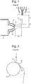
- Fig. 1 shows schematically a conventional standard impactor spray source. This comprises a pneumatic nebulizer assembly 1, a desolvation heater 4, an impactor target 5 and a mass spectrometer inlet assembly comprising cone gas nozzle 6, ion inlet orifice 8 and first vacuum region 9.
- the nebuliser assembly 1 is composed of an inner liquid capillary 2 and an outer gas capillary 3 which delivers a high velocity stream of gas at the nebulizer tip to aid the atomization of the liquid solvent flow.
- the inner liquid capillary 2 may have an internal diameter of 130 ⁇ m and an outside diameter of 270 ⁇ m.
- the outer gas capillary 3 may have an inside diameter of 330 ⁇ m.
- the gas supply for example nitrogen
- the gas supply for example nitrogen
- liquid flow rates of 0.1 to 1 mL/min are commonly used.
- a heated desolvation gas for example nitrogen flows between the nebulizer 1 and the heater 4 at a flow rate of typically 1200 L/hr.
- the high velocity stream of droplets from the nebulizer 1 impact on a 1.6 mm diameter stainless steel, cylindrical rod target 5.
- the surface of the rod target 5 is polished and smooth.
- the illustrated dimensions x 1 , y 1 and y 2 are typically 5 mm, 3 mm and 7 mm, respectively.
- the nebulizer 1 and impactor target 5 are typically held at 0 V and 1 kV, respectively.
- the mass spectrometer inlet is typically close to ground potential (for example 0-100 V).
- a nitrogen curtain gas flow of typically 150 L/hr passes between the cone gas nozzle 6 and the ion inlet cone 10. Ions, charged particles or neutrals that are contained within the gas flow wake 7 from the impactor target 5 can enter the mass spectrometer via the ion inlet orifice 8 which forms a boundary between the first vacuum region 9 of the MS and the atmospheric pressure region of the source enclosure.
- the gas flow wake 7 follows the curvature of the target (Coanda effect) and is swung in the direction of the ion inlet orifice 8 which results in a greater ion signal intensity.
- a nebulizer produces a stream of high velocity liquid droplets in a supersonic gas jet that impinges on a metallic rod target that is held at high voltage and is in close proximity to the nebuliser tip.
- WO2013/093517 and WO2014/064399 disclose arrangements according to the preamble of claim 1.
- WO2014064400 discloses improved reducibility of impact-based ioinisation source for low and high organic mobile phase compositions using a mesh target.
- EP1855306 (“Cristoni”) discloses an ionisation source and method for mass spectrometry.
- WO2004/034011 discloses an ionisation source for mass spectrometry analysis.
- an ion source as claimed in claim 1.
- Modifications to the target surface of an Impactor Spray ion source are proposed, which are designed to encourage additional vortex flow behaviour to enhance the performance of an impactor spray source.
- Conventional Impactor Spray ion sources involve a target that is typically a planar, curved surface and does not comprise a structure that is configured to disturb gas flowing along its surface. It has been recognised that vortex flow patterns at the target surface may play an important role in the nebulisation, desolvation and ionisation processes in Impactor Spray ion sources, and the present disclosure aims to utilise this recognition.
- the above ion source requires the target to comprise the one or more structures configured to disturb gas flowing along or across its surface. This is very distinct from, for example, WO2013/093517 (“Micromass”) in which the surface of the target is completely smooth.
- the stream predominantly of droplets are caused, in use, to impact upon the one or more targets thereby ionising the droplets to form said plurality of ions.
- the one or more structures may comprise one or more vortex generating structures, wherein the vortex generating structures are optionally configured to cause a vortex and/or turbulence in gas flowing past the one or more vortex generating structures.
- the one or more structures are configured to promote surface flow vortices that encourage gas flow to remain attached to the surface.
- the one or more structures optionally comprise an aerodynamic shape or profile configured to promote surface flow vortices that encourage gas flow to remain attached to the surface.
- the one or more structures may be positioned downstream of a stagnation point or line, and/or upstream of a separation point or line.
- the one or more structures may comprise one or more strakes or fins having a longitudinal axis that is parallel, off-parallel or perpendicular to the general direction of gas flowing over or around the target.
- the one or more structures may comprise a protuberance extending from a surface of the one or more targets and/or a notch or cavity extending into a surface of the one or more targets.
- the one or more structures may comprise at least one of:
- the one or more structures may be positioned within a predominant direction of gas flowing past the one or more targets.
- the one or more structures may be aligned with a predominant direction of gas flowing past the one or more targets.
- the one or more targets may comprise a cylindrical tube or rod.
- a or the predominant direction of gas flowing past the one or more targets may be along or around a portion of the surface, circumference, or circumferential surface of the cylindrical tube.
- the one or more targets may comprise a planar surface in the form of a plate, and a or the predominant direction of gas flowing past said one or more targets may be across or along said planar surface.
- a height or depth of the one or more structures may be equivalent to, or comparable to a boundary layer thickness of the gas flowing past the one or more targets.
- a height or depth of the one or more structures may be within +/- 0%, 10%, 15%, 20%, 30%, 40%, 50%, 100%, 200%, 500%, 1000%, 2500% or 5000% of a boundary layer thickness of the gas flowing past the one or more targets.
- a height or depth of the one or more structures, and/or a distance or spacing between adjacent structures may be greater than, equal to, or less than: (i) 1 ⁇ m; (ii) 2 ⁇ m; (iii) 5 ⁇ m; (iv) 10 ⁇ m; (v) 15 ⁇ m; (vi) 20 ⁇ m; (vii) 25 ⁇ m; (viii) 30 ⁇ m; (ix) 35 ⁇ m; (x) 40 ⁇ m; (xi) 45 ⁇ m; (xii) 50 ⁇ m; (xiii) 60 ⁇ m; (ixv) 70 ⁇ m; (xv) 80 ⁇ m; (xvi) 90 ⁇ m; (xvii) 100 ⁇ m; (xviii) 150 ⁇ m; (ixx) 200 ⁇ m; (xx) 300 ⁇ m; (xxi) 400 ⁇ m; or (xxii) 500 ⁇ m.
- the ion source may comprise an Atmospheric Pressure lonisation ("API”) ion source.
- API Atmospheric Pressure lonisation
- a mass spectrometer comprising an ion source as described above.
- structure may refer to a microstructure, for example having a dimension less than: (i) 1 ⁇ m; (ii) 2 ⁇ m; (iii) 5 ⁇ m; (iv) 10 ⁇ m; (v) 15 ⁇ m; (vi) 20 ⁇ m; (vii) 25 ⁇ m; (viii) 30 ⁇ m; (ix) 35 ⁇ m; (x) 40 ⁇ m; (xi) 45 ⁇ m; (xii) 50 ⁇ m; (xiii) 60 ⁇ m; (ixv) 70 ⁇ m; (xv) 80 ⁇ m; (xvi) 90 ⁇ m; (xvii) 100 ⁇ m; (xviii) 150 ⁇ m; (ixx) 200 ⁇ m; (xx) 300 ⁇ m; (xxi) 400 ⁇ m; or (xxii) 500 ⁇ m.
- the mass spectrometer may further comprise either:
- the mass spectrometer further comprises a device arranged and adapted to supply an AC or RF voltage to the electrodes.
- the AC or RF voltage optionally has an amplitude selected from the group consisting of: (i) about ⁇ 50 V peak to peak; (ii) about 50-100 V peak to peak; (iii) about 100-150 V peak to peak; (iv) about 150-200 V peak to peak; (v) about 200-250 V peak to peak; (vi) about 250-300 V peak to peak; (vii) about 300-350 V peak to peak; (viii) about 350-400 V peak to peak; (ix) about 400-450 V peak to peak; (x) about 450-500 V peak to peak; and (xi) > about 500 V peak to peak.
- the AC or RF voltage may have a frequency selected from the group consisting of: (i) ⁇ about 100 kHz; (ii) about 100-200 kHz; (iii) about 200-300 kHz; (iv) about 300-400 kHz; (v) about 400-500 kHz; (vi) about 0.5-1.0 MHz; (vii) about 1.0-1.5 MHz; (viii) about 1.5-2.0 MHz; (ix) about 2.0-2.5 MHz; (x) about 2.5-3.0 MHz; (xi) about 3.0-3.5 MHz; (xii) about 3.5-4.0 MHz; (xiii) about 4.0-4.5 MHz; (xiv) about 4.5-5.0 MHz; (xv) about 5.0-5.5 MHz; (xvi) about 5.5-6.0 MHz; (xvii) about 6.0-6.5 MHz; (xviii) about 6.5-7.0 MHz; (xix) about 7.0-7.5 MHz; (xx) about 7.5-8.0 MHz
- the mass spectrometer may also comprise a chromatography or other separation device upstream of an ion source.
- the chromatography separation device comprises a liquid chromatography or gas chromatography device.
- the separation device may comprise: (i) a Capillary Electrophoresis (“CE”) separation device; (ii) a Capillary Electrochromatography (“CEC”) separation device; (iii) a substantially rigid ceramic-based multilayer microfluidic substrate (“ceramic tile”) separation device; or (iv) a supercritical fluid chromatography separation device.
- the ion guide may be maintained at a pressure selected from the group consisting of: (i) ⁇ about 0.0001 mbar; (ii) about 0.0001-0.001 mbar; (iii) about 0.001-0.01 mbar; (iv) about 0.01-0.1 mbar; (v) about 0.1-1 mbar; (vi) about 1-10 mbar; (vii) about 10-100 mbar; (viii) about 100-1000 mbar; and (ix) > about 1000 mbar.
- analyte ions may be subjected to Electron Transfer Dissociation ("ETD") fragmentation in an Electron Transfer Dissociation fragmentation device.
- ETD Electron Transfer Dissociation
- Analyte ions may be caused to interact with ETD reagent ions within an ion guide or fragmentation device.
- Electron Transfer Dissociation either: (a) analyte ions are fragmented or are induced to dissociate and form product or fragment ions upon interacting with reagent ions; and/or (b) electrons are transferred from one or more reagent anions or negatively charged ions to one or more multiply charged analyte cations or positively charged ions whereupon at least some of the multiply charged analyte cations or positively charged ions are induced to dissociate and form product or fragment ions; and/or (c) analyte ions are fragmented or are induced to dissociate and form product or fragment ions upon interacting with neutral reagent gas molecules or atoms or a non-ionic reagent gas; and/or (d) electrons are transferred from one or more neutral, non-ionic or uncharged basic gases or vapours to one or more multiply charged analyte cations or positively charged ions whereupon at least some of the multiply charged ana
- the multiply charged analyte cations or positively charged ions may comprise peptides, polypeptides, proteins or biomolecules.
- the reagent anions or negatively charged ions are derived from a polyaromatic hydrocarbon or a substituted polyaromatic hydrocarbon; and/or (b) the reagent anions or negatively charged ions are derived from the group consisting of: (i) anthracene; (ii) 9,10 diphenyl-anthracene; (iii) naphthalene; (iv) fluorine; (v) phenanthrene; (vi) pyrene; (vii) fluoranthene; (viii) chrysene; (ix) triphenylene; (x) perylene; (xi) acridine; (xii) 2,2' dipyridyl; (xiii) 2,2' biquinoline; (xiv) 9-anthracenecarbonitrile; (xv) dibenzothiophene; (xvi) 1,10'-phenanthroline
- the process of Electron Transfer Dissociation fragmentation comprises interacting analyte ions with reagent ions, wherein the reagent ions comprise dicyanobenzene, 4-nitrotoluene or azulene.
- a chromatography detector may be provided wherein the chromatography detector comprises either:
- the mass spectrometer may be operated in various modes of operation including a mass spectrometry ("MS”) mode of operation, a tandem mass spectrometry (“MS/MS”) mode of operation, a mode of operation in which parent or precursor ions are alternatively fragmented or reacted so as to produce fragment or product ions, and not fragmented or reacted or fragmented or reacted to a lesser degree, a Multiple Reaction Monitoring (“MRM”) mode of operation, a Data Dependent Analysis (“DDA”) mode of operation, a Data Independent Analysis (“DIA”) mode of operation, a Quantification mode of operation or an Ion Mobility Spectrometry (“IMS”) mode of operation.
- MRM Multiple Reaction Monitoring
- DDA Data Dependent Analysis
- DIA Data Independent Analysis
- IMS Ion Mobility Spectrometry
- a point may be reached where the flow becomes attached to the surface and the local surface velocity may become zero. This may be known as the stagnation point 11 and is shown schematically for an Impactor Spray geometry in Fig. 2 .
- the stagnation region 13 may be bounded by the stagnation point 11 where the flow optionally becomes attached to the surface, and the separation point 12 where the flow optionally separates from the surface.
- Fig. 2 shows the gas streamline displaced to the right hand side of the rod axis, it is understood that a centralized gas flow from the Impactor Spray nebulizer may result in two symmetrical streamlines on either side of the target 5.
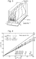
- Fig. 3 shows an illustration of a counter-rotating pair of surface vortices.
- ⁇ /D versus R e -0.5 for various turbulence intensities (Tu) is shown in Fig. 4 .
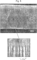
- Fig. 5 shows a Scanning Electron Microscope ("SEM") image of an Impactor Spray target (for example a 1.6 mm diameter, stainless steel Impactor Spray target) which was used as described above for the analysis of analytes contained in protein-precipitated human plasma.
- SEM Scanning Electron Microscope
- the granular, circular “halo” is due to the deposition of involatile components of the plasma and is outside of the area of interest for the present discussion.
- the SEM image was taken in the same direction as the impinging droplet stream and nebulizer gas jet.
- the cross (+) in Fig. 5 may represent an approximation of the impact point of the centre of the incoming gas jet.
- a close examination of the circled region of the image reveals a linear series of striation marks which are aligned with the direction of the flow streamlines. These striation marks may be evidence of the existence of counter-rotating surface vortices as described.
- the distance y 1 between the nebulizer tip and the target is typically 3 mm.
- these surface vortices may play an important role in the shearing of liquid droplets which could enhance the so-called “ion spray” and “sonic spray” mechanisms that yield gas phase ions and charged droplets in API sources.
- these cross flow surface channels may guide surface liquid towards the separation point where secondary droplets or ions may be ejected following a period of double layer formation within the surface liquid filaments (or rolling droplets).
- FIG. 6 An experimental geometry is shown schematically in Fig. 6 , in which a surface groove 14, with an equivalent width to the stagnation length (0.65 mm), is cut longitudinally into a 1.6 mm diameter stainless steel rod target 50. It has been shown that by rotating the position of the groove 14 with respect to the stagnation region (upper right hand quadrant), significant sensitivity decreases may be observed when the groove overlaps the stagnation region.
- Fig. 7 shows the effect of target groove position on the relative signal intensity for an Impactor Spray/Mass Spectrometry analysis of busiprone and reserpine which were infused into the source at a concentration of 0.125 pg/ ⁇ L and a flow rate of 0.8 mL/min.
- the highest sensitivity is observed when the groove is positioned well away from the stagnation zone (upper right hand quadrant).
- the lowest sensitivity is observed when the groove completely overlaps the upper quadrant, where presumably, the stagnation region is overwhelmed by turbulence such that the clear definition between a stagnation zone and free-stream flow no longer exists.
- the two additional reference points for busiprone and reserpine were obtained from a different target which contained no groove, but had a 1.6 mm diameter.
- aircraft wings incorporate vortex generators which are attached along the length of the wing in a position that is downstream but close to the stagnation line. These are typically triangular, rectangular or square features that are most effective when their height is equivalent to the thickness of the boundary layer at their point of attachment to the wing.
- a vortex generator can also take the form of an elongated strake or fin that is aligned in the direction of the flow streamlines.
- Historical hot-wire measurements have also shown that surface vortex disturbances can extend to as far as fifty boundary layer thicknesses so it may be expected that the useful height range of a vortex generating structure may be 1-50 times the boundary layer thickness ( ⁇ ).
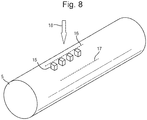
- Fig. 8 shows a schematic example of a cylindrical rod target 50 in accordance with an embodiment.
- Target 50 may have surface structures 15, or microstructures, that may serve the purpose of creating surface flow vortices.
- the surface flow vortices may encourage the flow to remain attached to the target surface.
- the size of the structures is exaggerated in Fig. 8 (which is schematic) and may be 10-100 ⁇ m in size.
- the target may be 1.6 mm in diameter.
- the microstructures may be located downstream from a stagnation line 16 and may be located upstream from a separation line (17).
- the size or height of the microstructures may be comparable or equivalent to the thickness of the boundary layer of gas flowing around the target. This can create the most effectiveness when attempting to generate vortices using the microstructures.
- microstructures are shown on the upper right hand quadrant of the target in Fig. 8 , an additional set of microstructures may be placed symmetrically on the upper left hand quadrant.
- the incoming nebulizer droplet stream 18 may be symmetrical, i.e. directed to the Top Dead Centre ("TDC") of the target.
- TDC Top Dead Centre
- the cylindrical rod target 5 could instead be a plate target, optionally comprising a planar surface in the form of a plate.
- the plate target may comprise one or more structures or microstructures on its surface.
- the structures or microstructures could comprise or further comprise one or more strakes or fins.
- the strakes or fins may have a longitudinal axis that is parallel, off-parallel or perpendicular to the general direction of gas flowing over or around the target.
- the strakes or fins may act to alter the direction of gas flowing past the surface and/or promote surface flow vortices to optionally encourage gas flow to remain attached to said surface.
- the strakes or fins may acheive this by having an aerodynamic shape or profile.
- the disclosed aspects and embodiments optionally increase the sensitivity of existing Impactor Spray ion sources and optionally provide a wider range of target types and geometries.
Landscapes
- Chemical & Material Sciences (AREA)
- Analytical Chemistry (AREA)
- Physics & Mathematics (AREA)
- Engineering & Computer Science (AREA)
- Plasma & Fusion (AREA)
- Dispersion Chemistry (AREA)
- Other Investigation Or Analysis Of Materials By Electrical Means (AREA)
- Electron Tubes For Measurement (AREA)
Applications Claiming Priority (3)
| Application Number | Priority Date | Filing Date | Title |
|---|---|---|---|
| GBGB1414596.5A GB201414596D0 (en) | 2014-08-18 | 2014-08-18 | Impactor Spray API source with vortex Generators |
| EP14181248 | 2014-08-18 | ||
| PCT/GB2015/052390 WO2016027073A1 (en) | 2014-08-18 | 2015-08-18 | Impactor spray ion source |
Publications (2)
| Publication Number | Publication Date |
|---|---|
| EP3183740A1 EP3183740A1 (en) | 2017-06-28 |
| EP3183740B1 true EP3183740B1 (en) | 2018-06-27 |
Family
ID=54011041
Family Applications (1)
| Application Number | Title | Priority Date | Filing Date |
|---|---|---|---|
| EP15756203.4A Active EP3183740B1 (en) | 2014-08-18 | 2015-08-18 | Impactor spray ion source |
Country Status (6)
| Country | Link |
|---|---|
| US (1) | US10262851B2 (enExample) |
| EP (1) | EP3183740B1 (enExample) |
| JP (2) | JP2017526131A (enExample) |
| CN (1) | CN106663587B (enExample) |
| GB (1) | GB2533184B (enExample) |
| WO (1) | WO2016027073A1 (enExample) |
Families Citing this family (5)
| Publication number | Priority date | Publication date | Assignee | Title |
|---|---|---|---|---|
| GB2567793B (en) * | 2017-04-13 | 2023-03-22 | Micromass Ltd | A method of fragmenting and charge reducing biomolecules |
| CN109841485B (zh) * | 2017-11-27 | 2020-05-08 | 中国科学院大连化学物理研究所 | 一种利用空气动力学辅助的方法提高离子传输效率的装置 |
| GB201807914D0 (en) * | 2018-05-16 | 2018-06-27 | Micromass Ltd | Impactor spray or electrospray ionisation ion source |
| CN110993481B (zh) * | 2019-11-13 | 2022-11-15 | 上海裕达实业有限公司 | 基于康达效应的电喷雾电离源辅助电离装置 |
| CN115531790A (zh) * | 2022-10-08 | 2022-12-30 | 南开大学 | 一种剧毒紫精类化合物的降解方法 |
Family Cites Families (7)
| Publication number | Priority date | Publication date | Assignee | Title |
|---|---|---|---|---|
| JP3379510B2 (ja) * | 1993-12-09 | 2003-02-24 | 株式会社日立製作所 | 液体クロマトグラフ結合型質量分析装置 |
| JP3307384B2 (ja) * | 1993-12-09 | 2002-07-24 | 株式会社日立製作所 | 液体クロマトグラフ結合型質量分析装置 |
| US7368728B2 (en) * | 2002-10-10 | 2008-05-06 | Universita' Degli Studi Di Milano | Ionization source for mass spectrometry analysis |
| EP1855306B1 (en) * | 2006-05-11 | 2019-11-13 | ISB - Ion Source & Biotechnologies S.R.L. | Ionization source and method for mass spectrometry |
| CA2860102A1 (en) * | 2011-12-23 | 2013-06-27 | Stevan Bajic | Interfacing capillary electrophoresis to a mass spectrometer via an impactor spray ionization source |
| JP6030771B2 (ja) * | 2012-10-25 | 2016-11-24 | マイクロマス ユーケー リミテッド | 二次液滴の減少を支援するためのインソース表面イオン化構造体への圧電振動 |
| CA2886655A1 (en) * | 2012-10-25 | 2014-05-01 | Micromass Uk Limited | Improved reproducibility of impact-based ionization source for low and high organic mobile phase compositions using a mesh target |
-
2015
- 2015-08-18 CN CN201580042818.2A patent/CN106663587B/zh active Active
- 2015-08-18 GB GB1514635.0A patent/GB2533184B/en active Active
- 2015-08-18 JP JP2017509769A patent/JP2017526131A/ja active Pending
- 2015-08-18 EP EP15756203.4A patent/EP3183740B1/en active Active
- 2015-08-18 WO PCT/GB2015/052390 patent/WO2016027073A1/en not_active Ceased
- 2015-08-18 US US15/504,180 patent/US10262851B2/en active Active
-
2019
- 2019-09-27 JP JP2019176665A patent/JP7018416B2/ja active Active
Non-Patent Citations (1)
| Title |
|---|
| None * |
Also Published As
| Publication number | Publication date |
|---|---|
| US20170263428A1 (en) | 2017-09-14 |
| EP3183740A1 (en) | 2017-06-28 |
| CN106663587B (zh) | 2019-09-27 |
| WO2016027073A1 (en) | 2016-02-25 |
| GB2533184B (en) | 2019-01-16 |
| GB201514635D0 (en) | 2015-09-30 |
| US10262851B2 (en) | 2019-04-16 |
| JP2020024923A (ja) | 2020-02-13 |
| CN106663587A (zh) | 2017-05-10 |
| JP7018416B2 (ja) | 2022-02-10 |
| JP2017526131A (ja) | 2017-09-07 |
| GB2533184A (en) | 2016-06-15 |
Similar Documents
| Publication | Publication Date | Title |
|---|---|---|
| JP7018416B2 (ja) | インパクタスプレーイオン源 | |
| US10679840B2 (en) | Miniature ion source of fixed geometry | |
| US20160372313A1 (en) | Sample Introduction System for Spectrometers | |
| GB2546407A (en) | Secondary Ultrasonic Nebulisation | |
| US10217622B2 (en) | Ambient ionisation with an impactor spray source | |
| US9651527B2 (en) | Ring shaped counter electrode to improve beam stability and compound sensitivity on a ceramic tile type microfluidic device | |
| US10032612B2 (en) | Two-dimensional separation and imaging technique for the rapid analysis of biological samples | |
| US20180308676A1 (en) | Ion source | |
| US9953819B2 (en) | Impactor spray atmospheric pressure ion source with target paddle | |
| EP3610497B1 (en) | Maldi target plate | |
| US10217623B2 (en) | Secondary electrospray ionization at reduced pressure | |
| GB2535835B (en) | A two-dimensional separation and imaging technique for the rapid analysis of biological samples | |
| GB2560262A (en) | Ambient ionisation with an impactor spray source | |
| GB2526397A (en) | Impactor spray atmospheric pressure ion source with target paddle | |
| GB2542941A (en) | Ion source alignment | |
| GB2520390A (en) | Miniature ion source of fixed geometry |
Legal Events
| Date | Code | Title | Description |
|---|---|---|---|
| STAA | Information on the status of an ep patent application or granted ep patent |
Free format text: STATUS: THE INTERNATIONAL PUBLICATION HAS BEEN MADE |
|
| PUAI | Public reference made under article 153(3) epc to a published international application that has entered the european phase |
Free format text: ORIGINAL CODE: 0009012 |
|
| STAA | Information on the status of an ep patent application or granted ep patent |
Free format text: STATUS: REQUEST FOR EXAMINATION WAS MADE |
|
| 17P | Request for examination filed |
Effective date: 20170317 |
|
| AK | Designated contracting states |
Kind code of ref document: A1 Designated state(s): AL AT BE BG CH CY CZ DE DK EE ES FI FR GB GR HR HU IE IS IT LI LT LU LV MC MK MT NL NO PL PT RO RS SE SI SK SM TR |
|
| AX | Request for extension of the european patent |
Extension state: BA ME |
|
| DAV | Request for validation of the european patent (deleted) | ||
| DAX | Request for extension of the european patent (deleted) | ||
| GRAP | Despatch of communication of intention to grant a patent |
Free format text: ORIGINAL CODE: EPIDOSNIGR1 |
|
| STAA | Information on the status of an ep patent application or granted ep patent |
Free format text: STATUS: GRANT OF PATENT IS INTENDED |
|
| INTG | Intention to grant announced |
Effective date: 20180117 |
|
| GRAS | Grant fee paid |
Free format text: ORIGINAL CODE: EPIDOSNIGR3 |
|
| GRAA | (expected) grant |
Free format text: ORIGINAL CODE: 0009210 |
|
| STAA | Information on the status of an ep patent application or granted ep patent |
Free format text: STATUS: THE PATENT HAS BEEN GRANTED |
|
| AK | Designated contracting states |
Kind code of ref document: B1 Designated state(s): AL AT BE BG CH CY CZ DE DK EE ES FI FR GB GR HR HU IE IS IT LI LT LU LV MC MK MT NL NO PL PT RO RS SE SI SK SM TR |
|
| REG | Reference to a national code |
Ref country code: GB Ref legal event code: FG4D |
|
| REG | Reference to a national code |
Ref country code: AT Ref legal event code: REF Ref document number: 1013043 Country of ref document: AT Kind code of ref document: T Effective date: 20180715 |
|
| REG | Reference to a national code |
Ref country code: IE Ref legal event code: FG4D |
|
| REG | Reference to a national code |
Ref country code: DE Ref legal event code: R096 Ref document number: 602015012802 Country of ref document: DE |
|
| PG25 | Lapsed in a contracting state [announced via postgrant information from national office to epo] |
Ref country code: SE Free format text: LAPSE BECAUSE OF FAILURE TO SUBMIT A TRANSLATION OF THE DESCRIPTION OR TO PAY THE FEE WITHIN THE PRESCRIBED TIME-LIMIT Effective date: 20180627 Ref country code: LT Free format text: LAPSE BECAUSE OF FAILURE TO SUBMIT A TRANSLATION OF THE DESCRIPTION OR TO PAY THE FEE WITHIN THE PRESCRIBED TIME-LIMIT Effective date: 20180627 Ref country code: FI Free format text: LAPSE BECAUSE OF FAILURE TO SUBMIT A TRANSLATION OF THE DESCRIPTION OR TO PAY THE FEE WITHIN THE PRESCRIBED TIME-LIMIT Effective date: 20180627 Ref country code: BG Free format text: LAPSE BECAUSE OF FAILURE TO SUBMIT A TRANSLATION OF THE DESCRIPTION OR TO PAY THE FEE WITHIN THE PRESCRIBED TIME-LIMIT Effective date: 20180927 Ref country code: NO Free format text: LAPSE BECAUSE OF FAILURE TO SUBMIT A TRANSLATION OF THE DESCRIPTION OR TO PAY THE FEE WITHIN THE PRESCRIBED TIME-LIMIT Effective date: 20180927 |
|
| REG | Reference to a national code |
Ref country code: NL Ref legal event code: MP Effective date: 20180627 |
|
| REG | Reference to a national code |
Ref country code: LT Ref legal event code: MG4D |
|
| PG25 | Lapsed in a contracting state [announced via postgrant information from national office to epo] |
Ref country code: LV Free format text: LAPSE BECAUSE OF FAILURE TO SUBMIT A TRANSLATION OF THE DESCRIPTION OR TO PAY THE FEE WITHIN THE PRESCRIBED TIME-LIMIT Effective date: 20180627 Ref country code: RS Free format text: LAPSE BECAUSE OF FAILURE TO SUBMIT A TRANSLATION OF THE DESCRIPTION OR TO PAY THE FEE WITHIN THE PRESCRIBED TIME-LIMIT Effective date: 20180627 Ref country code: HR Free format text: LAPSE BECAUSE OF FAILURE TO SUBMIT A TRANSLATION OF THE DESCRIPTION OR TO PAY THE FEE WITHIN THE PRESCRIBED TIME-LIMIT Effective date: 20180627 Ref country code: GR Free format text: LAPSE BECAUSE OF FAILURE TO SUBMIT A TRANSLATION OF THE DESCRIPTION OR TO PAY THE FEE WITHIN THE PRESCRIBED TIME-LIMIT Effective date: 20180928 |
|
| REG | Reference to a national code |
Ref country code: AT Ref legal event code: MK05 Ref document number: 1013043 Country of ref document: AT Kind code of ref document: T Effective date: 20180627 |
|
| PG25 | Lapsed in a contracting state [announced via postgrant information from national office to epo] |
Ref country code: NL Free format text: LAPSE BECAUSE OF FAILURE TO SUBMIT A TRANSLATION OF THE DESCRIPTION OR TO PAY THE FEE WITHIN THE PRESCRIBED TIME-LIMIT Effective date: 20180627 |
|
| PG25 | Lapsed in a contracting state [announced via postgrant information from national office to epo] |
Ref country code: CZ Free format text: LAPSE BECAUSE OF FAILURE TO SUBMIT A TRANSLATION OF THE DESCRIPTION OR TO PAY THE FEE WITHIN THE PRESCRIBED TIME-LIMIT Effective date: 20180627 Ref country code: SK Free format text: LAPSE BECAUSE OF FAILURE TO SUBMIT A TRANSLATION OF THE DESCRIPTION OR TO PAY THE FEE WITHIN THE PRESCRIBED TIME-LIMIT Effective date: 20180627 Ref country code: EE Free format text: LAPSE BECAUSE OF FAILURE TO SUBMIT A TRANSLATION OF THE DESCRIPTION OR TO PAY THE FEE WITHIN THE PRESCRIBED TIME-LIMIT Effective date: 20180627 Ref country code: IS Free format text: LAPSE BECAUSE OF FAILURE TO SUBMIT A TRANSLATION OF THE DESCRIPTION OR TO PAY THE FEE WITHIN THE PRESCRIBED TIME-LIMIT Effective date: 20181027 Ref country code: PL Free format text: LAPSE BECAUSE OF FAILURE TO SUBMIT A TRANSLATION OF THE DESCRIPTION OR TO PAY THE FEE WITHIN THE PRESCRIBED TIME-LIMIT Effective date: 20180627 Ref country code: AT Free format text: LAPSE BECAUSE OF FAILURE TO SUBMIT A TRANSLATION OF THE DESCRIPTION OR TO PAY THE FEE WITHIN THE PRESCRIBED TIME-LIMIT Effective date: 20180627 Ref country code: RO Free format text: LAPSE BECAUSE OF FAILURE TO SUBMIT A TRANSLATION OF THE DESCRIPTION OR TO PAY THE FEE WITHIN THE PRESCRIBED TIME-LIMIT Effective date: 20180627 |
|
| PG25 | Lapsed in a contracting state [announced via postgrant information from national office to epo] |
Ref country code: IT Free format text: LAPSE BECAUSE OF FAILURE TO SUBMIT A TRANSLATION OF THE DESCRIPTION OR TO PAY THE FEE WITHIN THE PRESCRIBED TIME-LIMIT Effective date: 20180627 Ref country code: SM Free format text: LAPSE BECAUSE OF FAILURE TO SUBMIT A TRANSLATION OF THE DESCRIPTION OR TO PAY THE FEE WITHIN THE PRESCRIBED TIME-LIMIT Effective date: 20180627 Ref country code: ES Free format text: LAPSE BECAUSE OF FAILURE TO SUBMIT A TRANSLATION OF THE DESCRIPTION OR TO PAY THE FEE WITHIN THE PRESCRIBED TIME-LIMIT Effective date: 20180627 |
|
| REG | Reference to a national code |
Ref country code: DE Ref legal event code: R097 Ref document number: 602015012802 Country of ref document: DE |
|
| PG25 | Lapsed in a contracting state [announced via postgrant information from national office to epo] |
Ref country code: MC Free format text: LAPSE BECAUSE OF FAILURE TO SUBMIT A TRANSLATION OF THE DESCRIPTION OR TO PAY THE FEE WITHIN THE PRESCRIBED TIME-LIMIT Effective date: 20180627 |
|
| REG | Reference to a national code |
Ref country code: CH Ref legal event code: PL |
|
| PG25 | Lapsed in a contracting state [announced via postgrant information from national office to epo] |
Ref country code: CH Free format text: LAPSE BECAUSE OF NON-PAYMENT OF DUE FEES Effective date: 20180831 Ref country code: LU Free format text: LAPSE BECAUSE OF NON-PAYMENT OF DUE FEES Effective date: 20180818 Ref country code: LI Free format text: LAPSE BECAUSE OF NON-PAYMENT OF DUE FEES Effective date: 20180831 |
|
| PLBE | No opposition filed within time limit |
Free format text: ORIGINAL CODE: 0009261 |
|
| STAA | Information on the status of an ep patent application or granted ep patent |
Free format text: STATUS: NO OPPOSITION FILED WITHIN TIME LIMIT |
|
| REG | Reference to a national code |
Ref country code: BE Ref legal event code: MM Effective date: 20180831 |
|
| REG | Reference to a national code |
Ref country code: IE Ref legal event code: MM4A |
|
| PG25 | Lapsed in a contracting state [announced via postgrant information from national office to epo] |
Ref country code: DK Free format text: LAPSE BECAUSE OF FAILURE TO SUBMIT A TRANSLATION OF THE DESCRIPTION OR TO PAY THE FEE WITHIN THE PRESCRIBED TIME-LIMIT Effective date: 20180627 |
|
| 26N | No opposition filed |
Effective date: 20190328 |
|
| PG25 | Lapsed in a contracting state [announced via postgrant information from national office to epo] |
Ref country code: IE Free format text: LAPSE BECAUSE OF NON-PAYMENT OF DUE FEES Effective date: 20180818 |
|
| PG25 | Lapsed in a contracting state [announced via postgrant information from national office to epo] |
Ref country code: FR Free format text: LAPSE BECAUSE OF NON-PAYMENT OF DUE FEES Effective date: 20180827 Ref country code: SI Free format text: LAPSE BECAUSE OF FAILURE TO SUBMIT A TRANSLATION OF THE DESCRIPTION OR TO PAY THE FEE WITHIN THE PRESCRIBED TIME-LIMIT Effective date: 20180627 Ref country code: BE Free format text: LAPSE BECAUSE OF NON-PAYMENT OF DUE FEES Effective date: 20180831 |
|
| PG25 | Lapsed in a contracting state [announced via postgrant information from national office to epo] |
Ref country code: AL Free format text: LAPSE BECAUSE OF FAILURE TO SUBMIT A TRANSLATION OF THE DESCRIPTION OR TO PAY THE FEE WITHIN THE PRESCRIBED TIME-LIMIT Effective date: 20180627 |
|
| PG25 | Lapsed in a contracting state [announced via postgrant information from national office to epo] |
Ref country code: MT Free format text: LAPSE BECAUSE OF NON-PAYMENT OF DUE FEES Effective date: 20180818 |
|
| PG25 | Lapsed in a contracting state [announced via postgrant information from national office to epo] |
Ref country code: TR Free format text: LAPSE BECAUSE OF FAILURE TO SUBMIT A TRANSLATION OF THE DESCRIPTION OR TO PAY THE FEE WITHIN THE PRESCRIBED TIME-LIMIT Effective date: 20180627 |
|
| PG25 | Lapsed in a contracting state [announced via postgrant information from national office to epo] |
Ref country code: PT Free format text: LAPSE BECAUSE OF FAILURE TO SUBMIT A TRANSLATION OF THE DESCRIPTION OR TO PAY THE FEE WITHIN THE PRESCRIBED TIME-LIMIT Effective date: 20180627 |
|
| PG25 | Lapsed in a contracting state [announced via postgrant information from national office to epo] |
Ref country code: CY Free format text: LAPSE BECAUSE OF FAILURE TO SUBMIT A TRANSLATION OF THE DESCRIPTION OR TO PAY THE FEE WITHIN THE PRESCRIBED TIME-LIMIT Effective date: 20180627 Ref country code: HU Free format text: LAPSE BECAUSE OF FAILURE TO SUBMIT A TRANSLATION OF THE DESCRIPTION OR TO PAY THE FEE WITHIN THE PRESCRIBED TIME-LIMIT; INVALID AB INITIO Effective date: 20150818 Ref country code: MK Free format text: LAPSE BECAUSE OF NON-PAYMENT OF DUE FEES Effective date: 20180627 |
|
| P01 | Opt-out of the competence of the unified patent court (upc) registered |
Effective date: 20230506 |
|
| PGFP | Annual fee paid to national office [announced via postgrant information from national office to epo] |
Ref country code: DE Payment date: 20250724 Year of fee payment: 11 |
|
| PGFP | Annual fee paid to national office [announced via postgrant information from national office to epo] |
Ref country code: GB Payment date: 20250725 Year of fee payment: 11 |