EP3183131B1 - Ensemble de vitre, vitrage et profil d'étanchéité de vitre - Google Patents
Ensemble de vitre, vitrage et profil d'étanchéité de vitre Download PDFInfo
- Publication number
- EP3183131B1 EP3183131B1 EP16700982.8A EP16700982A EP3183131B1 EP 3183131 B1 EP3183131 B1 EP 3183131B1 EP 16700982 A EP16700982 A EP 16700982A EP 3183131 B1 EP3183131 B1 EP 3183131B1
- Authority
- EP
- European Patent Office
- Prior art keywords
- guiding
- window
- sealing
- limb
- mounting
- Prior art date
- Legal status (The legal status is an assumption and is not a legal conclusion. Google has not performed a legal analysis and makes no representation as to the accuracy of the status listed.)
- Not-in-force
Links
Images


Classifications
-
- B—PERFORMING OPERATIONS; TRANSPORTING
- B60—VEHICLES IN GENERAL
- B60J—WINDOWS, WINDSCREENS, NON-FIXED ROOFS, DOORS, OR SIMILAR DEVICES FOR VEHICLES; REMOVABLE EXTERNAL PROTECTIVE COVERINGS SPECIALLY ADAPTED FOR VEHICLES
- B60J10/00—Sealing arrangements
- B60J10/70—Sealing arrangements specially adapted for windows or windscreens
- B60J10/74—Sealing arrangements specially adapted for windows or windscreens for sliding window panes, e.g. sash guides
- B60J10/79—Sealing arrangements specially adapted for windows or windscreens for sliding window panes, e.g. sash guides for flush-glass windows, i.e. for windows flush with the vehicle body or the window frame
-
- B—PERFORMING OPERATIONS; TRANSPORTING
- B60—VEHICLES IN GENERAL
- B60J—WINDOWS, WINDSCREENS, NON-FIXED ROOFS, DOORS, OR SIMILAR DEVICES FOR VEHICLES; REMOVABLE EXTERNAL PROTECTIVE COVERINGS SPECIALLY ADAPTED FOR VEHICLES
- B60J1/00—Windows; Windscreens; Accessories therefor
- B60J1/08—Windows; Windscreens; Accessories therefor arranged at vehicle sides
- B60J1/12—Windows; Windscreens; Accessories therefor arranged at vehicle sides adjustable
- B60J1/16—Windows; Windscreens; Accessories therefor arranged at vehicle sides adjustable slidable
- B60J1/17—Windows; Windscreens; Accessories therefor arranged at vehicle sides adjustable slidable vertically
-
- B—PERFORMING OPERATIONS; TRANSPORTING
- B60—VEHICLES IN GENERAL
- B60J—WINDOWS, WINDSCREENS, NON-FIXED ROOFS, DOORS, OR SIMILAR DEVICES FOR VEHICLES; REMOVABLE EXTERNAL PROTECTIVE COVERINGS SPECIALLY ADAPTED FOR VEHICLES
- B60J10/00—Sealing arrangements
- B60J10/20—Sealing arrangements characterised by the shape
- B60J10/26—Sealing arrangements characterised by the shape characterised by the surface shape
- B60J10/265—Sealing arrangements characterised by the shape characterised by the surface shape the surface being primarily decorative
-
- B—PERFORMING OPERATIONS; TRANSPORTING
- B60—VEHICLES IN GENERAL
- B60J—WINDOWS, WINDSCREENS, NON-FIXED ROOFS, DOORS, OR SIMILAR DEVICES FOR VEHICLES; REMOVABLE EXTERNAL PROTECTIVE COVERINGS SPECIALLY ADAPTED FOR VEHICLES
- B60J10/00—Sealing arrangements
- B60J10/20—Sealing arrangements characterised by the shape
- B60J10/27—Sealing arrangements characterised by the shape having projections, grooves or channels in the longitudinal direction
-
- B—PERFORMING OPERATIONS; TRANSPORTING
- B60—VEHICLES IN GENERAL
- B60J—WINDOWS, WINDSCREENS, NON-FIXED ROOFS, DOORS, OR SIMILAR DEVICES FOR VEHICLES; REMOVABLE EXTERNAL PROTECTIVE COVERINGS SPECIALLY ADAPTED FOR VEHICLES
- B60J5/00—Doors
- B60J5/04—Doors arranged at the vehicle sides
- B60J5/0401—Upper door structure
- B60J5/0402—Upper door structure window frame details, including sash guides and glass runs
Definitions
- the invention generally relates to a window assembly for a motor vehicle. Furthermore, the invention relates to a window pane and a window sealing profile.
- pillar As used herein, terms defining directions or positions, such as “left”, “right”, “front”, “rear”, “top”, “bottom”, “inner”, “outer”, and the like are referring to a view of a motor vehicle from one of the seats.
- the B pillar is rear of the A pillar but front of the C pillar.
- Directions or positions of components are typically designated according to their installed positions.
- pillar as used herein is not limited to the usual load bearing pillar of a motor vehicle.
- the term “pillar” should rather be construed to further include portions of the motor vehicle in the vicinity of the actual load bearing pillars where accommodating and guiding of the window pane takes place.
- EP 2 142 394 B1 discloses a guide arrangement for a movable window pane of a motor vehicle.
- the guide arrangement includes a first movable window pane, and a second movable window pane.
- the end face of the first window pane and the end face of the second window pane are arranged opposite, and at a distance from, one another.
- a first guide part is fastened to the first window pane.
- a second guide part is fastened to the second window pane.
- a first receptacle for the first guide part, and a second receptacle for the second guide part are provided.
- EP 1 794 402 B1 discloses a division bar assembly to be received between an associated fixed window and an associated movable window of a vehicle.
- the division bar assembly comprises a support adapted to be secured to the associated fixed window, a guide adapted to be affixed to the associated movable window and adapted to extend from an inner surface thereof, and a guide member extending from the support including a cavity dimensioned to receive the guide.
- US 2012 / 0 025 564 A1 discloses a flush glass system module for a motor vehicle door frame defining a window opening having an upper edge and a lower edge for receiving a window having an inner surface.
- the flush glass system module comprises a front slider adapted to mount to the inner surface of the window.
- the first applique is disposed entirely on the inner surface side of the window.
- DE 10 2005 013 581 B4 discloses a structure of a door window frame of a vehicle having a portion for holding a door window pane.
- a window pane seal is provided at one end portion of the door window pane.
- An outer surface of the window seal, an outer surface of the door window pane and an outer surface of an outer wall of the door window frame are flush on the outer side of the vehicle.
- the window pane arrangement for a motor vehicle having a window pane.
- the window pane arrangement comprises a front guiding rail and a rear guiding rail.
- the window pane is guided in the front guiding rail and the rear guiding rail.
- At least one of the guiding rails is configured as two-parts having a guiding member and a closure member connected to the guiding member.
- the guiding member and the closure member define between them a channel for receiving the window pane.
- the guiding member and the closure member are connected by means of a form-fitting connection.
- JP 60 151718 U discloses a door structure of an automobile. Air resistance and sound generation when the automobile is in operation are achieved by a flush surface.
- the door structure aims to reduce vibrations of the door glass due to pressure differences between the inside and the outside of the automobile.
- FR 2 739 060 A1 discloses a window of a vehicle door.
- the window can be moved relative to the door by a runner assembly and a runner guide.
- the runner is fixed to the window and the guide is fixed to the door structure such that the runner holds the window flush with the adjacent bodywork element.
- the runner comprises a rigid support in which is housed a seal mounted on the runner guide.
- the branches of the U shaped seal wrap around the window guide and have internal smooth parts.
- the smoot parts are in contact with the guide. Extended parts having sealing lips are supported on the guide.
- the runner is glued onto the window in a zone hidden by a silk screen.
- a seal is housed between the window and the adjacent bodywork part.
- IT 1 211 321 B discloses a window for a motor vehicle.
- the window comprises a frame defining a window opening and a window pane guided vertically in the frame.
- the window pane is disposed in such a way that in its raised position the window presents an external surface substantially flush relative to the surfaces of the adjacent bodywork of the upper edge, the front edge, and the rear edge of the window opening.
- DE 42 10 035 A1 discloses a guide for a window of a side door of a vehicle.
- the guide has a U-shaped guide channel.
- the guide channel is open towards the window pane and enclosed by a guide rail.
- the guide channel accommodates a sliding block by which the glass pane is guided in the longitudinal direction of the vehicle only.
- To guide the glass in the transverse direction a seal is provided. The seal grips the edge of the glass and has a reinforcing inlay. With this construction positioning loads on the glass may be reduced.
- the invention is based on the object to provide a smooth transition from the rim portions of a window pane to the neighboring portions of the vehicle.
- a window assembly according to claim 1.
- Advantageous embodiments of the window assembly are subject-matter of claims 2 to 9.
- a window pane for an advantageous window assembly is subject-matter of claim 10.
- a window sealing profile for an advantageous window assembly is subject-matter of claim 11.
- the invention provides a window assembly for a window opening, in particular a side window opening, of a motor vehicle having a front-rear direction.
- the window assembly comprises a door frame member, a movable window pane, a window sealing profile, and a guiding bracket.
- a front pillar or a rear pillar are an example for a door frame member, respectively.
- the movable window pane includes a window section and a guiding section.
- the guiding section comprises a guiding surface being able to contact a guiding member.
- the window sealing profile includes a mounting portion that is fastened to the door frame member.
- the mounting portion comprises a mounting leg and a mounting base. The mounting base is connected to the mounting leg.
- the mounting leg, the mounting base, or both have a bracket support configured to support a guiding bracket.
- the window sealing profile further includes a sealing portion for sealing the window pane.
- the guiding bracket includes a trimming surface and is configured to guide the window pane along a direction of movement between an open position and a closed position.
- the guiding bracket is further configured to be fastened to the window sealing profile and to the window pane. When in the fastened state, the guiding bracket simultaneously engages the window sealing profile and the window pane. Furthermore, when in the fastened state, the guiding bracket applies an inward directed force so as to press the window pane towards the window sealing profile.
- the guiding bracket comprises a fastening limb, a guiding limb, and an intermediate limb connecting the fastening limb to the guiding limb.
- the guiding bracket is provided with a separate guiding member.
- the guiding member is disposed at the end of the guiding limb.
- the guiding section comprises a receiving opening that is defined by the guiding surface.
- the receiving opening extends in a receiving direction which is parallel to the front-rear direction.
- the guiding member when in the fastened state, is received in the receiving opening.
- the guiding member is supporting the guiding section in a sliding manner.
- the outer surface and the window outer surface are arranged to be flush. With this configuration, a smooth surface of the motor vehicle is possible. In particular the transition between the window pane and the door frame member, such as a front pillar or rear pillar, can be achieved.
- the mounting portion is configured to form-fittingly engage the door frame member.
- the mounting leg may include a mounting protrusion.
- the mounting portion may further include a reinforcing member which is preferably embedded in the mounting leg and/or the mounting base.
- the mounting leg can have a rear inner bracket support and a front inner bracket support, wherein the rear bracket support is disposed to the rear of the front bracket support.
- the mounting portion may include an inner mounting leg and an outer mounting leg.
- the inner mounting leg and the outer mounting leg are an example for a mounting leg, respectively.
- the mounting base preferably connects the inner mounting leg to the outer mounting leg.
- the mounting protrusion can be disposed at the inner mounting leg and/or the outer mounting leg, preferably at the respective end.
- the reinforcing member is preferably embedded in the inner mounting leg, the outer mounting leg and/or the mounting base.
- the mounting portion may comprise a rear inner bracket support, a front inner bracket support, and/or a front bracket support.
- the rear inner bracket support, the front inner bracket support, and/or the front bracket support are an example for a bracket support, respectively.
- the rear inner bracket support and additionally or alternatively the outer bracket support may be disposed on the inner mounting leg.
- the mounting base includes a front bracket support.
- the sealing portion comprises a front sealing lip.
- the front sealing lip is preferably disposed at the mounting leg, in particular at the outer mounting leg.
- the front sealing lip can protrude outward or away from the mounting leg, in particular from the outer mounting leg.
- the front sealing lip is disposed at the transition between the mounting base and the mounting leg, in particular the transition between the mounting base and the outer mounting leg.
- the front sealing lip may engage the window pane.
- the front sealing lip is preferably interposed between the guiding bracket and the door frame member.
- the front sealing lip can have a front sealing surface, an example for a sealing surface, coated with lubricant varnish or flock.
- the sealing portion can include a rear sealing lip.
- the rear sealing lip can protrude outward from the mounting leg, in particular from the outer mounting leg.
- the rear sealing lip is disposed at the free end of the mounting leg, in particular at the free end of the outer mounting leg.
- the rear sealing lip may engage the window pane.
- the rear sealing lip is preferably interposed between the guiding bracket and the door frame member.
- the rear sealing lip can have a rear sealing surface, an example for a sealing surface, coated with lubricant varnish or flock.
- the front sealing lip is disposed to the front, whereas the rear sealing lip is disposed to the rear.
- the sealing portion can include an inner sealing bulge.
- the inner sealing bulge can protrude outward from the mounting leg, in particular from the outer mounting leg.
- the inner sealing bulge is disposed at the center of the mounting leg, in particular at the center of the outer mounting leg.
- the inner sealing bulge may engage the window pane.
- the inner sealing bulge is preferably interposed between the guiding bracket and the door frame member.
- the inner sealing bulge can have a bulge sealing surface, an example for a sealing surface, coated with lubricant varnish or flock.
- the inner sealing bulge is interposed between the front sealing lip and the rear sealing lip.
- the sealing portion may comprise an intermediate sealing member.
- the intermediate sealing member can be a separate member.
- the intermediate sealing member can be disposed on the door frame member, in particular on the front pillar and/or on the rear pillar. More preferred, the intermediate sealing member is interposed between the fastening leg and the outer leg. Most preferred, the intermediate sealing member is disposed on the base leg.
- the intermediate sealing member can include a front contact surface, a rear contact surface, and an exposed surface interposed between the front contact surface and the rear contact surface.
- the front contact surface and/or the rear contact surface may be coated with lubricating varnish or flock.
- the exposed surface is preferably arranged to be flush with the outer surface and the outer window surface. Additionally or alternatively, the exposed surface may be arranged to be flush with the outer surface and the outer window surface.
- the window pane may comprise a window section and a guiding section which are integrally formed as a single unitary member.
- the window pane is preferably made of a transparent thermoplastic like polycarbonate or polymethyl methacrylate (PMMA), for example.
- the guiding section may include a supporting portion.
- the guiding section can include a guiding arm.
- the guiding section also may comprise a connecting arm connecting the window section and the guiding arm.
- the guiding section can include a reinforcing member, which is advantageously embedded in the guiding arm and/or the connecting arm.
- the guiding section extends along between 50 % and 100 %, in particular between 70 % and 100 %, of a dimension of the window section.
- the fastening limb, the guiding limb, and the intermediate limb cooperate, in particular are disposed, in such a way, that the inward directed force is generated due to bending of the fastening limb and/or the guiding limb relative to the intermediate limb, respectively.
- the fastening limb, the intermediate limb, and the guiding limb are preferably integrally formed as a unitary member using a thermoplastic or a metal like aluminum.
- the fastening limb, the intermediate limb, and the guiding limb may be arranged in a C-like shape.
- the fastening limb may include a fastening hook.
- the guiding member may have a guiding support being configured to support the window pane.
- the guiding member is made from a lubricant material, e.g. polyethylene.
- the guiding member can be coated with a lubricant varnish or flock.
- the invention further provides a window pane for an advantageous embodiment of a window assembly.
- the window pane may include any combination of features relating to the window pane as previously described.
- a window pane for an advantageous embodiment of a window assembly comprises a window section and a guiding section being configured to cooperate with a guiding bracket.
- the window section and the guiding section are integrally formed as a single unitary member.
- the invention further provides a window sealing profile.
- the window sealing profile may include any combination of features relating to the window sealing profile as previously described.
- a window sealing profile for an advantageous window assembly comprises a mounting portion and a sealing portion.
- the mounting portion is configured to mount the window sealing profile to the door frame member.
- the mounting portion includes an inner mounting leg, an outer mounting leg, and a mounting base which connects the inner mounting leg to the outer mounting leg.
- the sealing portion is configured to seal a window pane.
- the sealing portion includes a front sealing lip disposed at the transition between the inner mounting leg and the mounting base. It is suggested, that the sealing portion comprises an inner sealing bulge disposed separate from and to the rear relative to the front sealing lip. Alternatively, it is suggested that the sealing portion comprises an inner sealing lip disposed at the transition between the inner mounting leg and the mounting base.
- the invention further provides a vehicle door comprising any of the previous described advantageous embodiments of a window assembly, a window pane, or a window sealing profile. Still further, the invention provides a vehicle comprising an advantageous embodiment of a vehicle door, a window assembly, a window pane, or a window sealing profile.
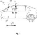
- a motor vehicle 10 comprises a front-rear direction FR and a side window opening 11 extending along the front-rear direction FR.
- the motor vehicle 10 further comprises a vehicle door 20 having a front pillar 21 and a rear pillar 22.
- the front pillar 21 is disposed towards the front of the vehicle door 20, whereas the rear pillar 22 is disposed towards the rear of the vehicle door 20.
- the front pillar 21 and the rear pillar 22 need not be a load bearing structure.
- the front pillar 21 and the rear pillar 22 are an example for a door frame member, respectively.
- the vehicle door 20 comprises a window pane 130.
- the window pane 130 is partially arranged within the front pillar 21 and the rear pillar 22 in order to guide the window pane 130, when opening or closing.
- the window pane 130 comprises a window section 131 which is usually transparent.
- the term transparent shall be construed to include a configuration wherein the window section 131 serves as a protection against sunlight.
- the window pane 130 includes a guiding section 136 which allows to guide the window pane 130, when opening or closing.
- a first embodiment of a window assembly 170 will be described with reference to the rear pillar 22 serving as the door frame member. It should be noted, that in the first embodiment and in all subsequently described embodiments, the front pillar 21 may additionally or alternatively serve as the door frame member.
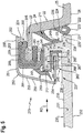
- the window assembly 170 comprises a rear pillar 22, a window sealing profile 100, a window pane 130, and a guiding bracket 150.
- the rear pillar 22 comprises a fastening leg 23, a base leg 24, and an outer leg 25 having an outer surface 26.
- the fastening leg 23 has provided at its end a mounting protrusion 27.
- the base leg 24 connects the fastening leg 23 to the outer leg 25.
- the fastening leg 23, the outer leg 24, and the base leg 25 are arranged step-like.
- the window sealing profile 100 includes a mounting portion 101 being configured to be fastened to the rear pillar 22.
- the mounting portion 101 is integrally formed as a single unitary member.
- the mounting portion 101 comprises an inner mounting leg 102, an outer mounting leg 103, and a mounting base 104.
- the inner mounting leg 102 and the outer mounting leg 103 are an example for a mounting leg, respectively.
- the inner mounting leg 102 has provided at its end a mounting protrusion 105. Adjacent to the mounting protrusion 105 a rear inner bracket support 106 is provided.
- the mounting base 104 connects the inner mounting leg 102 to the outer mounting leg 103. At the transition between the inner mounting leg 102 and the mounting base 104 a front inner bracket support 107 is provided.
- the rear inner bracket support 106 and the front inner bracket support 107 are an example for a bracket support, respectively.
- the rear inner bracket support 106 is disposed to the rear of the front inner bracket support.
- a front bracket support 108 which is also an example for a bracket support, is disposed roughly in the center of the mounting base 104.
- the outer mounting leg 103 comprises a front sealing lip 110, a rear sealing lip 111, and an inner sealing bulge 112.
- the front sealing lip 110, the rear sealing lip 111, and the inner sealing bulge 112 are an example for a sealing portion, respectively.
- the front sealing lip 110 is disposed at the transition between the outer mounting leg 103 and the mounting base 104.
- the front sealing lip 110 protrudes with an angle between 80° and 110°, preferably orthogonally, away from the outer mounting leg 103 and outward.
- the front sealing lip 110 comprises a front sealing surface 113 facing to the rear and being coated with flock.
- the rear sealing lip 111 is disposed at the end of the outer mounting leg 103.
- the rear sealing lip 111 protrudes with an angle between 80° and 110°, preferably orthogonally, away from the outer mounting leg 103 and outward.
- the rear sealing lip 111 comprises a rear sealing surface 114 facing to the front and being coated with lubricant varnish.
- the inner sealing bulge 112 is interposed between the front sealing lip 110 and the rear sealing lip 111.
- the inner sealing bulge 112 protrudes away from the outer mounting leg 103 and outward.
- the inner sealing bulge 112 roughly takes an (semi-)elliptical cross-section.
- the inner sealing bulge 112 comprises a bulge sealing surface 115 facing outward and being coated with lubricant varnish.
- the front sealing surface 113, the rear sealing surface 114 and the bulge sealing surface 115 are an example for a sealing surface, respectively.
- the window sealing profile 100 further comprises an intermediate sealing member 120.
- the intermediate sealing member 120 is an example for a sealing portion.
- the intermediate sealing member 120 is disposed at rear pillar 22.
- the intermediate sealing member 120 protrudes from the base leg 24 outward and subsequently bends back to form a cavity 124.
- the cavity 124 is cooperatively defined by the intermediate sealing member 120 and the base leg 24.
- the intermediate sealing member 120 includes a front contact surface 121, a rear contact surface 122, and an exposed surface 123.
- the front contact surface 121 and the rear contact surface 122 are another example for a sealing surface, respectively.
- the front contact surface 121 is coated with flock, whereas the rear contact surface 122 is uncoated.
- the exposed surface 123 is facing outward and is interposed between the front contact surface 121 and the rear contact surface 122.
- the window pane 130 comprises a window section 131 and a guiding section 136.
- the window section 131 and the guiding section 136 are integrally formed as a single unitary member.
- the window section 131 is substantially transparent.
- the window section 131 comprises an outer window surface 132, an inner window surface 133, and an end portion 134 including an end face 135.
- the end face 135 is configured to contact the intermediate sealing member 120.
- the guiding section 136 comprises a connecting arm 139 a guiding arm 141, and a supporting portion 137.
- the supporting portion 137 is disposed on the side of the inner window surface 133 and has a step-like shape.
- the connecting arm 139 is disposed adjacent the end portion 134 and protrudes from the supporting portion 137, roughly orthogonal to the window section 131, and inward.
- the connecting arm 139 subsequently transitions into the guiding arm 141 which extends substantially in parallel to the window section 131 and to the front.
- the connecting arm 139 the guiding arm 141 and the supporting portion 137 define a receiving opening 145.
- a reinforcing member 146 is embedded in the connecting arm 139, in the guiding arm 141, and in the supporting portion 137.
- the reinforcing member 146 is substantially U-shaped and made of metal, such as steel or aluminum.
- the receiving opening 145 extends along a receiving direction RD, which is parallel to the front-rear direction FR.
- the supporting portion 137 includes a supporting surface 138 facing inward.
- the connecting arm 139 includes a connecting surface 140 facing forward.
- the guiding arm 141 includes an inner guiding surface 142 facing inward, an outer guiding surface 143 facing outward, and a front guiding surface 144 facing to the front.
- the supporting surface 138, the connecting surface 140, the inner guiding surface 142, the outer guiding surface 143, and the front guiding surface 144 are examples for a guiding surface, respectively. With this embodiment, the guiding surfaces are uncoated.
- the guiding bracket 150 includes a fastening limb 151, an intermediate limb 153, and a guiding limb 154.
- the fastening limb 151, the intermediate limb 153, and the guiding limb 154 are roughly arranged in a C-shape.
- the fastening limb 151 has provided at its end a fastening hook 152.
- the intermediate limb 153 connects the fastening limb 151 to the guiding limb 154.
- the guiding bracket 150 comprises a trimming surface 155 extending at least over the fastening limb 151 and the intermediate limb 153.
- the fastening limb 151, the intermediate limb 153, and the guiding limb 154 are integrally formed as a single unitary member and made of a thermoplastic or a metal, such as steel or aluminum.
- the guiding bracket 150 further comprises a guiding member 160.
- the guiding member 160 is disposed at the end of the guiding limb 154.
- the guiding member 160 includes an inner guiding part 161, a rear guiding part 164, and an outer guiding part 166.
- the inner guiding part 161 extends parallel to the guiding limb 154 and to the front.
- the inner guiding part 161 is disposed inward relative to the outer guiding part 166.
- the rear guiding part 164 connects the inner guiding part 161 to the outer guiding part 166.
- the rear guiding part 164 is disposed to the rear relative to the inner guiding part 161 and the outer guiding part 166.
- the outer guiding part 166 extends parallel to the guiding limb 154 and to the front.
- the outer guiding part 166 is disposed outward relative to the inner guiding part 161.
- the inner guiding part 161 comprises an inner front guiding support 162 and an inner rear guiding support 163.
- the inner front guiding support 162 and the inner rear guiding support 163 are an example for a guiding support, respectively.
- the inner front guiding support 162 protrudes from the inner guiding part 161 and inward.
- the inner front guiding support 162 is disposed at the end of the inner guiding part 161.
- the inner rear guiding support 163 protrudes from the inner guiding part 161 and inward.
- the inner rear guiding support 163 is disposed at the transition of the inner guiding part 161 to the rear guiding part 164.
- the inner front guiding support 162 and the inner rear guiding support 163 are spaced apart from each other in the receiving direction RD.
- the rear guiding part 164 comprises a rear guiding support 165.
- the rear guiding support 165 is an example for a guiding support.
- the rear guiding support 165 protrudes from the rear guiding part 164 and to the rear.
- the rear guiding support 165 is preferably disposed roughly at the center of the rear guiding part 164.
- the outer guiding part 166 comprises an outer front guiding support 167 and an outer rear guiding support 168.
- the outer front guiding support 167 and the outer rear guiding support 168 are an example for a guiding support, respectively.
- the outer front guiding support 167 protrudes from the outer guiding part 166 and inward.
- the outer front guiding support 167 is disposed at the end of the outer guiding part 166.
- the outer rear guiding support 168 protrudes from the outer guiding part 166 and inward.
- the outer rear guiding support 168 is disposed at the transition of the outer guiding part 166 to the rear guiding part 164.
- the outer front guiding support 167 and the outer rear guiding support 168 are spaced apart from each other in the receiving direction RD.
- the window sealing profile 100 is fastened to the rear pillar 22.
- the mounting portion 101 is pushed onto the fastening leg 23, wherein the fastening protrusion 27 and the mounting protrusion 105 form-fittingly engage each other.
- the window sealing profile 100 and the window pane 130 are arranged so that the sealing portion engages the window pane 130.
- the intermediate sealing member 120 is formed to the base leg 24.
- the intermediate sealing member 120 engages the end portion 134.
- the rear contact surface 122 engages the outer leg 25 and the front contact surface 121 engages the end face 135.
- the front sealing lip 110, the rear sealing lip 111, and the inner sealing bulge 112 engage the guiding section 136.
- the front sealing lip 110 and the inner sealing bulge 112 engage the guiding arm 141, whereas the rear sealing lip 111 engages the connecting arm 139.
- the front sealing lip 110 engages the front guiding surface 144 and the inner sealing bulge 112 engages the inner guiding surface 142.
- the guiding bracket 150 is fastened to the window sealing profile 100 so that the bracket supports are engaging and supporting the guiding bracket 150.
- the guiding member 160 is disposed in the receiving opening 145 and slidingly engages the guiding section 136, in particular the connecting arm 139, the guiding arm 141, and the supporting portion 137.
- the inner guiding part 161 engages the guiding arm 141
- the rear guiding part 164 engages the connecting arm 139
- the outer guiding part 166 engages the supporting portion 137.
- the outer surface 26, the exposed surface 123, and the outer window surface 132 are flush.
- the window assembly 170 is assembled by providing a rear pillar 22 having the intermediate sealing member 120. Subsequently, the window sealing profile 100 is fastened to the rear pillar 22. Next, the window pane 130 is arranged in engagement with the window sealing profile 100. Finally, the guiding bracket 150 is fastened so as to engage both the window sealing profile 100 and the window pane 130. The window pane 130 is now guided by the guiding bracket 150 during movement between the open position and the closed position, and vice versa.
- a second embodiment of a window assembly 270 will be described with reference to the rear pillar 22 serving as the door frame member. It should be noted, that in the first embodiment and in all subsequently described embodiments, the front pillar 21 may additionally or alternatively serve as the door frame member.
- the window assembly 270 comprises the rear pillar 22, a window sealing profile 200, a window pane 230, and a guiding bracket 250.
- the window sealing profile 200 includes a mounting portion 201 being configured to be fastened to the rear pillar 22.
- the mounting portion 201 is integrally formed as a single unitary member.
- the mounting portion 201 comprises an inner mounting leg 202, an outer mounting leg 203, and a mounting base 204.
- the inner mounting leg 202 and the outer mounting leg 203 are an example for a mounting leg, respectively.
- the inner mounting leg 202 has provided at its end a mounting protrusion 205. Adjacent to the mounting protrusion 205 an inner bracket support 206 is provided.
- the mounting base 204 connects the inner mounting leg 202 to the outer mounting leg 203.
- the inner bracket support 206 extends over the entire inner mounting leg 202.
- the outer mounting leg 203 comprises a front sealing lip 210, and an inner sealing lip 212.
- the front sealing lip 210, and the inner sealing lip 212 are an example for a sealing portion, respectively.
- the front sealing lip 210 is disposed at the transition between the outer mounting leg 203 and the mounting base 204.
- the front sealing lip 210 protrudes in a zig-zag pattern away from the outer mounting leg 203 and outward.
- the front sealing lip 210 comprises a front sealing surface 213 facing to the rear and being coated with lubricant varnish.
- the inner sealing lip 212 is disposed adjacent to the front sealing lip 210.
- the inner sealing lip 112 protrudes away from the outer mounting leg 203 with an angle between 30° and 60°, preferably with an angle of about 45°, to the rear and outward.
- the inner sealing lip 212 comprises an inner surface 215 facing outward and being coated with lubricant varnish.
- the front sealing surface 213 and the bulge sealing surface 215 are an example for a sealing surface, respectively.
- the window sealing profile 100 further comprises a rear sealing lip 211 and an intermediate sealing member 220.
- the rear sealing lip 211 and the intermediate sealing member 220 are an example for a sealing portion, respectively.
- the intermediate sealing member 220 is disposed at rear pillar 22.
- the intermediate sealing member 220 protrudes from the base leg 24 outward and subsequently bends back to form a cavity 224.
- the cavity 224 is cooperatively defined by the intermediate sealing member 220 and the base leg 24.
- the intermediate sealing member 220 includes a front contact surface 221, a rear contact surface 222, and an exposed surface 223.
- the front contact surface 221 and the rear contact surface 222 are another example for a sealing surface, respectively.
- the front contact surface 221 and the rear contact surface 222 are coated with lubricant varnish.
- the exposed surface 223 is facing outward and is interposed between the front contact surface 221 and the rear contact surface 222.
- the rear sealing lip 211 is disposed at the rear pillar 22.
- the rear sealing lip 211 protrudes from the base leg 24 and outward.
- the rear sealing lip 211 comprises a rear sealing surface 214 facing to the front and being coated with lubricant varnish.
- the rear sealing surface 214 is an example for a sealing surface
- the window pane 230 comprises a window section 231 and a guiding section 236.
- the window section 231 and the guiding section 236 are integrally formed as a single unitary member.
- the window section 231 is substantially transparent.
- the window section 231 comprises an outer window surface 232, an inner window surface 233, and an end portion 234 including an end face 235.
- the end face 235 is configured to contact the intermediate sealing member 220.
- the guiding section 236 comprises a connecting arm 232, a guiding arm 241, and a supporting portion 237.
- the supporting portion 237 is disposed on the side of the inner window surface 233 and has a step-like shape.
- the connecting arm 232 is disposed adjacent the end portion 234 and protrudes from the supporting portion 237, roughly orthogonal to the window section 231, and inward.
- the connecting arm 239 subsequently transitions into the guiding arm 241 which extends substantially in parallel to the window section 231 and to the front.
- the connecting arm 232, the guiding arm 241 and the supporting portion 237 define a receiving opening 245.
- the receiving opening 245 extends along a receiving direction RD, which is parallel to the front-rear direction FR.
- the supporting portion 237 includes a supporting surface 238 facing inward.
- the connecting arm 239 includes a front connecting surface 240a facing forward and a rear connecting surface 240b facing rearward.
- the guiding arm 241 includes an inner guiding surface 242 facing inward, an outer guiding surface 243 facing outward, and a front guiding surface 244 facing to the front.
- the supporting surface 238, the connecting surface 240, the inner guiding surface 242, the outer guiding surface 243, and the front guiding surface 244 are coated with lubricating varnish.
- the supporting surface 238, the connecting surface 240, the inner guiding surface 242, the outer guiding surface 243, and the front guiding surface 244 are examples for a guiding surface, respectively.
- the guiding bracket 250 includes a fastening limb 251, an intermediate limb 253, and a guiding limb 254.
- the fastening limb 251, the intermediate limb 253, and the guiding limb 254 are roughly arranged in a C-shape.
- the fastening limb 251 has provided at its end a fastening hook 252.
- the intermediate limb 253 connects the fastening limb 251 to the guiding limb 254.
- the guiding bracket 250 comprises a trimming surface 255 extending at least over the fastening limb 251 and the intermediate limb 253.
- the fastening limb 251, the intermediate limb 253, and the guiding limb 254 are integrally formed as a single unitary member and made of a thermoplastic or a metal, such as steel or aluminum.
- the guiding bracket 250 further comprises a guiding member 260.
- the guiding member 260 is disposed at the end of the guiding limb 254.
- the guiding member 260 includes an inner guiding part 261, a rear guiding part 264, and an outer guiding part 266.
- the inner guiding part 261 extends parallel to the guiding limb 254 and to the front.
- the inner guiding part 261 is disposed inward relative to the outer guiding part 266.
- the rear guiding part 264 connects the inner guiding part 261 to the outer guiding part 266.
- the rear guiding part 264 is disposed to the rear relative to the inner guiding part 261 and the outer guiding part 266.
- the outer guiding part 266 extends parallel to the guiding limb 254 and to the front.
- the outer guiding part 266 is disposed outward relative to the inner guiding part 261.
- the inner guiding part 261 comprises an inner guiding support 262 which is an example for a guiding support.
- the rear guiding part 264 comprises a rear guiding support 265.
- the rear guiding support 265 is an example for a guiding support.
- the window sealing profile 200 is fastened to the rear pillar 22.
- the mounting portion 201 is pushed onto the fastening leg 23, wherein the fastening protrusion 27 and the mounting protrusion 205 form-fittingly engage each other. Furthermore, the window sealing profile 200 and the window pane 230 are arranged so that the sealing portion engages the window pane 230.
- the intermediate sealing member 220 is formed to the base leg 24.
- the intermediate sealing member 220 engages the end portion 234. Specifically, the rear contact surface 222 engages the outer leg 25.
- the window pane 230 is arranged so that the end face 235 engages the front contact surface 221.
- the rear sealing lip 211 is formed to the base leg 24 and engages the guiding section 236. Specifically, the rear sealing lip 211 engages the connecting arm 239.
- the rear sealing lip 211 engages the rear connecting surface 240b. Furthermore, the front sealing lip 210 and the inner sealing lip 212 engage the guiding section 236. More specifically, the front sealing lip 210 and the inner sealing bulge 212 engage the guiding arm 241.
- the front sealing lip 210 preferably engages the front guiding surface 244, whereas the inner sealing lip 212 engages the inner guiding surface 242.
- the guiding bracket 250 is fastened to the window sealing profile 200 so that the inner bracket support 206 engages and supports the guiding bracket 250.
- the guiding member 260 is disposed in the receiving opening 245 and slidingly engages the guiding section 236, in particular the connecting arm 239 and the guiding arm 241.
- the guiding member 260 and the supporting portion 237 cooperatively define a gap 267. Specifically, the inner guiding part 261 engages the guiding arm 241 and the rear guiding part 264 engages the connecting arm 139.
- the window assembly 270 is assembled by providing a rear pillar 22 having the rear sealing lip 211 and the intermediate sealing member 220. Subsequently, the window sealing profile 200 is fastened to the rear pillar 22. Next, the window pane 230 is arranged in engagement with the window sealing profile 200. Finally, the guiding bracket 250 is fastened so as to engage both the window sealing profile 200 and the window pane 230. The window pane 230 is now guided by the guiding bracket 250 during movement between the open position and the closed position, and vice versa.
Landscapes
- Engineering & Computer Science (AREA)
- Mechanical Engineering (AREA)
- Seal Device For Vehicle (AREA)
- Window Of Vehicle (AREA)
Claims (11)
- Ensemble de fenêtre (170, 270) pour une ouverture de fenêtre (11) d'un véhicule automobile (10) ayant une direction avant/arrière (FR), comprenant :un élément d'encadrement de portière (21, 22) qui présente une surface extérieure (26) ;une vitre de fenêtre mobile (130, 230) qui présente une section de guidage (136, 236) et une section de fenêtre (131, 231) incluant une surface extérieure de fenêtre (132, 232), la section de guidage (136, 236) comprenant une surface de guidage (138, 140, 142, 143, 144, 240a, 240b, 242, 243, 244) étant configurée pour venir en contact avec un élément de guidage ;un profil d'étanchéité de fenêtre (100, 200) incluant une partie de montage (101, 201) qui est fixée à l'élément d'encadrement de portière (21, 22) et présentant une partie d'étanchéité (110, 111, 112, 120, 210, 211, 212, 220) qui est configurée pour étancher la vitre (130, 230), la partie de montage (101, 201) comprenant une jambe de montage (102, 103, 202, 203) et une base de montage (104, 204) qui est reliée à la jambe de montage (102, 103, 202, 203), la jambe de montage (102, 103, 202, 203) et/ou la base de montage (104, 204) présentant un support d'étrier (106, 206) configuré pour supporter un étrier de guidage (150, 250) ; etun étrier de guidage (150, 250) présentant une surface d'ajustage (155, 255) et étant configuré pour guider la vitre de fenêtre (130, 230) le long d'une direction de mouvement entre une position ouverte et une position fermée, l'étrier de guidage (150, 250) étant en outre configuré pour être fixé au profil d'étanchéité de fenêtre (100, 200) et à la vitre de fenêtre (130, 230).dans lequel l'étrier de guidage (150, 250), lorsqu'il se trouve dans l'état fixé, est simultanément en prise avec le profil d'étanchéité de fenêtre (100, 200) et la vitre de fenêtre (130, 230),dans lequel l'étrier de guidage (150, 250), lorsqu'il se trouve dans l'état fixé, est configuré pour appliquer une force (FI) dirigée vers l'intérieur de manière à presser la vitre de fenêtre (130, 230) vers le profil d'étanchéité de fenêtre (100, 200),caractérisé en ce que l'étrier de guidage (150, 250) comprend un bras de fixation (151, 251), un bras de guidage (154, 254) et un bras intermédiaire (153, 253) reliant le bras de fixation (151, 251) au bras de guidage (154, 254);dans lequel l'étrier de guidage (150, 250) comprend un élément de guidage (160, 260) séparé, l'élément de guidage (160, 260) étant agencé à l'extrémité du bras de guidage (154, 254) ;dans lequel la section de guidage (136, 236) comprend une ouverture de réception (145, 245) définie par la surface de guidage (138, 140, 142, 143, 144, 240a, 240b, 242, 243, 244) et s'étendant dans une direction de réception (RD) qui est parallèle à la direction avant/arrière ;dans lequel l'élément de guidage (160, 260), lorsqu'il est dans l'état fixé, est reçu dans l'ouverture de réception (145, 245) et supporte la section de guidage (136, 236) de manière coulissante.
- Ensemble de fenêtre (170, 270) selon la revendication 1, dans lequel la surface extérieure (26) et la surface extérieure de fenêtre (132, 232) sont disposées de manière à être en affleurement.
- Ensemble de fenêtre (170, 270) selon la revendication 1 ou 2, dans lequel le bras de fixation (151, 251), le bras de guidage (154, 254) et le bras intermédiaire (153, 253) coopèrent de telle manière que la force (FI) dirigée vers l'intérieur est engendrée par une flexion du bras de fixation (151, 251) et/ou du bras de guidage (154, 254) par rapport au bras intermédiaire (153, 253), respectivement.
- Ensemble de fenêtre (170, 270) selon l'une des revendications 1 à 3, dans lequel l'élément de guidage (160, 260) comprend un support de guidage (162, 163, 165, 167, 168, 262, 265) qui est configuré pour supporter la vitre de fenêtre (130, 230).
- Ensemble de fenêtre (170, 270) selon l'une des revendications 1 à 4, dans lequel la partie d'étanchéité comprend un élément d'étanchéité intermédiaire (120, 220) qui présente une surface de contact avant (121, 221) en prise avec la vitre de fenêtre (130, 230) et une surface de contact arrière (122, 222) en prise avec l'élément d'encadrement de portière (21, 22).
- Ensemble de fenêtre (170, 270) selon la revendication 5, dans lequel la vitre de fenêtre (130, 230) comprend une face terminale (135, 235) en prise avec l'élément d'étanchéité intermédiaire (120, 220).
- Ensemble de fenêtre (170, 270) selon la revendication 5 ou 6, dans lequel l'élément d'étanchéité intermédiaire (120, 220) comprend en outre une surface (123, 223) exposée, interposée entre la surface de contact avant (121, 221) et la surface de contact arrière (122, 222),
dans lequel la surface exposée (123, 223) est disposée de manière à être en affleurement ou en retrait par rapport à la surface extérieure (26) et à la surface de fenêtre extérieure (132, 232). - Ensemble de fenêtre (170, 270) selon l'une quelconque des revendications 1 à 7, dans lequel la partie d'étanchéité comprend une lèvre d'étanchéité avant (110, 210) qui est agencée à une transition entre la jambe de montage (102, 202) et la base de montage (104, 204).
- Ensemble de fenêtre (170, 270) selon l'une quelconque des revendications 1 à 8, dans lequel la partie d'étanchéité comprend une lèvre d'étanchéité arrière (111, 211) qui est agencée à une extrémité de la jambe de montage (102, 202) ou sur l'élément d'encadrement de portière (21, 22).
- Vitre de fenêtre (130, 230) pour un ensemble de fenêtre (170, 270) selon l'une quelconque des revendications 1 à 9, la vitre de fenêtre (130, 230, 330, 430) comprenant :une section de fenêtre (131, 231) ; etune section de guidage (136, 236) qui est configurée pour coopérer avec un étrier de guidage (150, 250),caractérisée en ce que la section de fenêtre (131, 231) et la section de guidage (136, 236) sont formées d'un seul tenant en tant qu'élément unitaire individuel.
- Profil d'étanchéité de fenêtre (100, 200) pour un ensemble de fenêtre (170, 270) selon l'une quelconque des revendications 1 à 10, le profil d'étanchéité de fenêtre comprenant :une partie de montage (101, 201) qui est configurée pour monter le profil d'étanchéité de fenêtre (100, 200) sur l'élément d'encadrement de portière (21, 22), la partie de montage ayant une jambe de montage intérieure (102, 202), une jambe de montage extérieure (103, 203) et une base de montage (104, 204) reliant la jambe de montage intérieure (102, 202) à la jambe de montage extérieure (103, 203) ; etune partie d'étanchéité qui est configurée pour étancher une vitre de fenêtre (130, 230), la partie d'étanchéité ayant une lèvre d'étanchéité avant (110, 210) agencée à la transition entre la jambe de montage intérieure (102, 202) et la base de montage (104, 204),dans lequel la partie d'étanchéité comprend un renflement d'étanchéité (112) agencé séparément depuis et vers l'arrière par rapport à la lèvre d'étanchéité avant (110),
oudans lequel la partie d'étanchéité comprend une lèvre d'étanchéité intérieure (212) agencée à la transition entre la jambe de montage intérieure (202) et la base de montage (204).
Applications Claiming Priority (2)
| Application Number | Priority Date | Filing Date | Title |
|---|---|---|---|
| EP15192663 | 2015-11-02 | ||
| PCT/EP2016/050919 WO2017076512A1 (fr) | 2015-11-02 | 2016-01-18 | Ensemble de vitre, vitrage et profil d'étanchéité de vitre |
Publications (2)
| Publication Number | Publication Date |
|---|---|
| EP3183131A1 EP3183131A1 (fr) | 2017-06-28 |
| EP3183131B1 true EP3183131B1 (fr) | 2018-07-25 |
Family
ID=54396771
Family Applications (1)
| Application Number | Title | Priority Date | Filing Date |
|---|---|---|---|
| EP16700982.8A Not-in-force EP3183131B1 (fr) | 2015-11-02 | 2016-01-18 | Ensemble de vitre, vitrage et profil d'étanchéité de vitre |
Country Status (5)
| Country | Link |
|---|---|
| US (1) | US10562385B2 (fr) |
| EP (1) | EP3183131B1 (fr) |
| CN (1) | CN108290480B (fr) |
| ES (1) | ES2692418T3 (fr) |
| WO (1) | WO2017076512A1 (fr) |
Cited By (1)
| Publication number | Priority date | Publication date | Assignee | Title |
|---|---|---|---|---|
| WO2023048664A1 (fr) * | 2021-09-27 | 2023-03-30 | Standard Profi̇l Otomoti̇v Sanayi̇ Ve Ti̇caret Anoni̇m Şi̇rketi̇ | Guide monolithique pour fenêtres coulissantes dans des véhicules |
Families Citing this family (8)
| Publication number | Priority date | Publication date | Assignee | Title |
|---|---|---|---|---|
| WO2017076513A1 (fr) * | 2015-11-02 | 2017-05-11 | Cooper Standard GmbH | Ensemble fenêtre, et porte de véhicule et véhicule présentant l'ensemble fenêtre |
| JP7087554B2 (ja) * | 2017-11-10 | 2022-06-21 | 株式会社アイシン | 車両ドアのドアサッシュ構造 |
| JP7095263B2 (ja) * | 2017-11-10 | 2022-07-05 | 株式会社アイシン | 車両ドアのウインドガラス支持構造 |
| JP7147485B2 (ja) * | 2017-12-08 | 2022-10-05 | Agc株式会社 | スライダ付きウインドウガラス及びその製造方法 |
| US11052731B2 (en) * | 2019-02-05 | 2021-07-06 | Volvo Car Corporation | Vehicle flush window system, a vehicle comprising same, and related assembly method |
| DE102019125811A1 (de) * | 2019-09-25 | 2021-03-25 | Cqlt Saargummi Technologies S.À.R.L. | Fensterführung und Kraftfahrzeugfenster |
| EP3988356B1 (fr) * | 2020-10-21 | 2023-04-12 | FCA Italy S.p.A. | Dispositif pour guider une vitre coulissante d'une porte latérale de véhicule automobile |
| WO2022214266A1 (fr) * | 2021-04-06 | 2022-10-13 | Bayerische Motoren Werke Aktiengesellschaft | Lève-vitre pour une vitre latérale d'un véhicule automobile |
Family Cites Families (40)
| Publication number | Priority date | Publication date | Assignee | Title |
|---|---|---|---|---|
| DE3153293C2 (de) * | 1981-12-11 | 1993-11-25 | Rockwell Golde Gmbh | Selbsttätig andrückende Abdichtanordnung für die Fensterscheibe eines vertikal verschiebbaren Fahrzeugfensters |
| DE3227153A1 (de) * | 1982-07-21 | 1984-02-02 | Ford-Werke AG, 5000 Köln | Fahrzeugtuer, insbesondere fuer personenkraftwagen |
| DE3313658C2 (de) * | 1983-04-15 | 1987-04-23 | Daimler-Benz Ag, 7000 Stuttgart | Aufbau für Personen- oder Kombinationskraftwagen |
| JPS6025520U (ja) * | 1983-07-29 | 1985-02-21 | トヨタ自動車株式会社 | 自動車のドア構造 |
| JPS6025521U (ja) * | 1983-07-29 | 1985-02-21 | トヨタ自動車株式会社 | 自動車のドア構造 |
| JPS60102125U (ja) * | 1983-12-19 | 1985-07-12 | トヨタ自動車株式会社 | 自動車のドア構造 |
| US4731951A (en) * | 1983-12-26 | 1988-03-22 | Toyota Jidosha Kabushiki Kaisha | Vehicle door structure |
| US4608779A (en) * | 1984-01-11 | 1986-09-02 | Mazda Motor Corporation | Automobile door assembly |
| JPS60151718A (ja) | 1984-01-19 | 1985-08-09 | Nissan Motor Co Ltd | ロボツト用教示装置 |
| US4604830A (en) * | 1984-01-31 | 1986-08-12 | Mazda Motor Corporation | Flush-surfaced automobile door assembly |
| JPS60151718U (ja) * | 1984-03-21 | 1985-10-08 | トヨタ自動車株式会社 | 自動車のドア構造 |
| JPH0349049Y2 (fr) * | 1985-03-13 | 1991-10-21 | ||
| IT1210806B (it) * | 1987-06-16 | 1989-09-29 | Ferrari Eng | Struttura di sopporto e di guida dei cristalli di una carrozzeria di un automobile |
| FR2620088B1 (fr) * | 1987-09-08 | 1989-12-15 | Peugeot | Dispositif de guidage pour vitre coulissante |
| IT1211321B (it) | 1987-09-25 | 1989-10-12 | Fiat Auto Spa | Finestrino verticalmente scorrevole con cristallo a filo per autoveicoli |
| DE3737736A1 (de) * | 1987-11-06 | 1989-05-24 | Daimler Benz Ag | Seitenaufbau fuer kraftfahrzeuge |
| FR2641025B1 (fr) * | 1988-12-28 | 1995-05-24 | Mesnel Sa Ets | |
| IT1237689B (it) * | 1989-12-15 | 1993-06-15 | Fiat Auto Spa | Porta per veicoli e metodo per la realizzazione della stessa. |
| DE4210035A1 (de) | 1992-03-27 | 1993-09-30 | Audi Ag | Scheibenführung |
| FR2739060B1 (fr) * | 1995-09-22 | 1998-06-05 | Peugeot | Dispositif permettant a une vitre mobile de porte de vehicule d'affleurer un element de carrosserie adjacent |
| US6141910A (en) * | 1997-05-28 | 2000-11-07 | Dura Global Technologies, Inc. | Door module having a windowpane which includes brackets for attaching the windowpane to the door module and for moving the windowpane |
| US6220650B1 (en) * | 2000-07-07 | 2001-04-24 | Donnelly Corporation | Vehicle window assembly |
| JP3929930B2 (ja) * | 2003-04-02 | 2007-06-13 | 本田技研工業株式会社 | 自動車用窓ガラスの支持構造 |
| JP2005297602A (ja) | 2004-04-06 | 2005-10-27 | Honda Motor Co Ltd | ドアサッシュ構造 |
| JP2006044360A (ja) * | 2004-08-02 | 2006-02-16 | Toyoda Gosei Co Ltd | ガラスラン |
| US20060059799A1 (en) | 2004-08-24 | 2006-03-23 | Cooper-Standard Automotive Inc. | Invisible division bar modular assembly |
| GB2432870A (en) * | 2005-11-18 | 2007-06-06 | Gdx North America Inc | Sealing assemblies and methods of making them |
| JP4873992B2 (ja) * | 2006-05-19 | 2012-02-08 | 鬼怒川ゴム工業株式会社 | 車両用グラスラン |
| DE102006053095A1 (de) | 2006-11-10 | 2008-05-15 | Metzeler Automotive Profile Systems Gmbh | Führungsanordnung für eine bewegbare Fensterscheibe, insbesondere eines Kraftfahrzeugs |
| JP5162184B2 (ja) | 2007-08-14 | 2013-03-13 | 株式会社エヌ・ティ・ティ・ドコモ | ユーザ装置、基地局及びチャネル品質情報報告方法 |
| FR2920112B1 (fr) * | 2007-08-24 | 2009-10-30 | Hutchinson Sa | Procede de fabrication d'un module superieur d'ouvrant pour un vitrage d'un vehicule, et un tel module |
| US20120025564A1 (en) | 2010-07-28 | 2012-02-02 | Magna International Inc. | Flush Glass System Module |
| CN102416850A (zh) * | 2010-09-27 | 2012-04-18 | 鬼怒川橡胶工业株式会社 | 门窗玻璃导槽的安装结构 |
| US8572898B2 (en) * | 2011-09-08 | 2013-11-05 | Ford Global Technologies, Llc | Method for assembling flush glass assembly |
| US8650802B2 (en) * | 2011-09-08 | 2014-02-18 | Ford Global Technologies, Llc | Vehicle (automobile) flush glass appearance assembly |
| US8646215B2 (en) * | 2011-09-08 | 2014-02-11 | Ford Global Technologies, Llc | Flush glass assembly interfaces |
| JP5846159B2 (ja) * | 2013-05-31 | 2016-01-20 | トヨタ自動車株式会社 | ウインドウガラスの支持構造 |
| DE102014005721B3 (de) | 2014-04-17 | 2015-08-13 | Audi Ag | Scheibenanordnung für ein Kraftfahrzeug |
| WO2017076513A1 (fr) * | 2015-11-02 | 2017-05-11 | Cooper Standard GmbH | Ensemble fenêtre, et porte de véhicule et véhicule présentant l'ensemble fenêtre |
| JP6371269B2 (ja) * | 2015-11-24 | 2018-08-08 | トヨタ自動車株式会社 | 車両用ドアガラス昇降構造 |
-
2016
- 2016-01-18 CN CN201680071438.6A patent/CN108290480B/zh not_active Expired - Fee Related
- 2016-01-18 WO PCT/EP2016/050919 patent/WO2017076512A1/fr active Application Filing
- 2016-01-18 US US15/773,104 patent/US10562385B2/en active Active
- 2016-01-18 ES ES16700982.8T patent/ES2692418T3/es active Active
- 2016-01-18 EP EP16700982.8A patent/EP3183131B1/fr not_active Not-in-force
Non-Patent Citations (1)
| Title |
|---|
| None * |
Cited By (1)
| Publication number | Priority date | Publication date | Assignee | Title |
|---|---|---|---|---|
| WO2023048664A1 (fr) * | 2021-09-27 | 2023-03-30 | Standard Profi̇l Otomoti̇v Sanayi̇ Ve Ti̇caret Anoni̇m Şi̇rketi̇ | Guide monolithique pour fenêtres coulissantes dans des véhicules |
Also Published As
| Publication number | Publication date |
|---|---|
| ES2692418T3 (es) | 2018-12-03 |
| US10562385B2 (en) | 2020-02-18 |
| WO2017076512A1 (fr) | 2017-05-11 |
| EP3183131A1 (fr) | 2017-06-28 |
| CN108290480B (zh) | 2019-06-18 |
| US20180319260A1 (en) | 2018-11-08 |
| CN108290480A (zh) | 2018-07-17 |
Similar Documents
| Publication | Publication Date | Title |
|---|---|---|
| EP3183131B1 (fr) | Ensemble de vitre, vitrage et profil d'étanchéité de vitre | |
| EP3183132B1 (fr) | Ensemble fenêtre, carreau de fenêtre et profil de guidage de fenêtre | |
| EP3183134B1 (fr) | Ensemble fenêtre et porte de véhicule et véhicule présentant l'ensemble fenêtre | |
| CN108463366B (zh) | 用于面齐平的窗玻璃设计的具有在框架侧的引导元件处的导入区域的车门组件和装配方法 | |
| US8166708B2 (en) | Integrated glass run and upper reveal with film | |
| CN103182922B (zh) | 车辆用车门框 | |
| US8915018B2 (en) | Slider window assembly | |
| EP1759960B1 (fr) | Structure de toit pour véhicule | |
| US8979181B2 (en) | Vehicle body structure | |
| US8567838B2 (en) | Vehicle body structure | |
| JP2008081108A (ja) | 自動車用ルーフフレーム | |
| WO2011014684A1 (fr) | Ensemble vitre réglable | |
| US20200031213A1 (en) | Flush glazed device for a vehicle door, door, motor vehicle, and corresponding production method and single-piece sealing device | |
| US8641118B2 (en) | Vehicle body structure | |
| WO2010080895A1 (fr) | Guide de vitre de véhicule | |
| CN208698689U (zh) | 一种外夹条前端盖、外夹条组件及外夹条组件安装结构 | |
| JP3314632B2 (ja) | サンルーフ車のルーフ構造 | |
| US4805958A (en) | Sunroof housing for automative vehicles | |
| US20120025561A1 (en) | Sealing mechanism for a collapsible roof | |
| JP2018172074A (ja) | 車両用バックドア | |
| CN116638932A (zh) | 车门的玻璃导槽组件及车辆 | |
| GB2627995A (en) | Vehicle window seal assembly | |
| JP2009227146A (ja) | 車両のスライドドアレールカバー構造 | |
| KR20010066493A (ko) | 자동차의 슬라이딩 도어용 가이드 레일의 보강구조 | |
| JPH08169238A (ja) | 自動車のスライドドアのセンターレール構造 |
Legal Events
| Date | Code | Title | Description |
|---|---|---|---|
| STAA | Information on the status of an ep patent application or granted ep patent |
Free format text: STATUS: UNKNOWN |
|
| STAA | Information on the status of an ep patent application or granted ep patent |
Free format text: STATUS: THE INTERNATIONAL PUBLICATION HAS BEEN MADE |
|
| PUAI | Public reference made under article 153(3) epc to a published international application that has entered the european phase |
Free format text: ORIGINAL CODE: 0009012 |
|
| STAA | Information on the status of an ep patent application or granted ep patent |
Free format text: STATUS: REQUEST FOR EXAMINATION WAS MADE |
|
| 17P | Request for examination filed |
Effective date: 20161219 |
|
| AK | Designated contracting states |
Kind code of ref document: A1 Designated state(s): AL AT BE BG CH CY CZ DE DK EE ES FI FR GB GR HR HU IE IS IT LI LT LU LV MC MK MT NL NO PL PT RO RS SE SI SK SM TR |
|
| AX | Request for extension of the european patent |
Extension state: BA ME |
|
| STAA | Information on the status of an ep patent application or granted ep patent |
Free format text: STATUS: EXAMINATION IS IN PROGRESS |
|
| 17Q | First examination report despatched |
Effective date: 20170704 |
|
| GRAP | Despatch of communication of intention to grant a patent |
Free format text: ORIGINAL CODE: EPIDOSNIGR1 |
|
| STAA | Information on the status of an ep patent application or granted ep patent |
Free format text: STATUS: GRANT OF PATENT IS INTENDED |
|
| DAV | Request for validation of the european patent (deleted) | ||
| DAX | Request for extension of the european patent (deleted) | ||
| INTG | Intention to grant announced |
Effective date: 20180504 |
|
| GRAS | Grant fee paid |
Free format text: ORIGINAL CODE: EPIDOSNIGR3 |
|
| GRAA | (expected) grant |
Free format text: ORIGINAL CODE: 0009210 |
|
| STAA | Information on the status of an ep patent application or granted ep patent |
Free format text: STATUS: THE PATENT HAS BEEN GRANTED |
|
| AK | Designated contracting states |
Kind code of ref document: B1 Designated state(s): AL AT BE BG CH CY CZ DE DK EE ES FI FR GB GR HR HU IE IS IT LI LT LU LV MC MK MT NL NO PL PT RO RS SE SI SK SM TR |
|
| REG | Reference to a national code |
Ref country code: GB Ref legal event code: FG4D |
|
| REG | Reference to a national code |
Ref country code: CH Ref legal event code: EP |
|
| REG | Reference to a national code |
Ref country code: AT Ref legal event code: REF Ref document number: 1021361 Country of ref document: AT Kind code of ref document: T Effective date: 20180815 |
|
| REG | Reference to a national code |
Ref country code: IE Ref legal event code: FG4D |
|
| REG | Reference to a national code |
Ref country code: DE Ref legal event code: R096 Ref document number: 602016004302 Country of ref document: DE |
|
| REG | Reference to a national code |
Ref country code: NL Ref legal event code: MP Effective date: 20180725 |
|
| REG | Reference to a national code |
Ref country code: ES Ref legal event code: FG2A Ref document number: 2692418 Country of ref document: ES Kind code of ref document: T3 Effective date: 20181203 |
|
| REG | Reference to a national code |
Ref country code: LT Ref legal event code: MG4D |
|
| PG25 | Lapsed in a contracting state [announced via postgrant information from national office to epo] |
Ref country code: NL Free format text: LAPSE BECAUSE OF FAILURE TO SUBMIT A TRANSLATION OF THE DESCRIPTION OR TO PAY THE FEE WITHIN THE PRESCRIBED TIME-LIMIT Effective date: 20180725 |
|
| REG | Reference to a national code |
Ref country code: AT Ref legal event code: MK05 Ref document number: 1021361 Country of ref document: AT Kind code of ref document: T Effective date: 20180725 |
|
| PG25 | Lapsed in a contracting state [announced via postgrant information from national office to epo] |
Ref country code: IS Free format text: LAPSE BECAUSE OF FAILURE TO SUBMIT A TRANSLATION OF THE DESCRIPTION OR TO PAY THE FEE WITHIN THE PRESCRIBED TIME-LIMIT Effective date: 20181125 Ref country code: FI Free format text: LAPSE BECAUSE OF FAILURE TO SUBMIT A TRANSLATION OF THE DESCRIPTION OR TO PAY THE FEE WITHIN THE PRESCRIBED TIME-LIMIT Effective date: 20180725 Ref country code: RS Free format text: LAPSE BECAUSE OF FAILURE TO SUBMIT A TRANSLATION OF THE DESCRIPTION OR TO PAY THE FEE WITHIN THE PRESCRIBED TIME-LIMIT Effective date: 20180725 Ref country code: GR Free format text: LAPSE BECAUSE OF FAILURE TO SUBMIT A TRANSLATION OF THE DESCRIPTION OR TO PAY THE FEE WITHIN THE PRESCRIBED TIME-LIMIT Effective date: 20181026 Ref country code: NO Free format text: LAPSE BECAUSE OF FAILURE TO SUBMIT A TRANSLATION OF THE DESCRIPTION OR TO PAY THE FEE WITHIN THE PRESCRIBED TIME-LIMIT Effective date: 20181025 Ref country code: SE Free format text: LAPSE BECAUSE OF FAILURE TO SUBMIT A TRANSLATION OF THE DESCRIPTION OR TO PAY THE FEE WITHIN THE PRESCRIBED TIME-LIMIT Effective date: 20180725 Ref country code: BG Free format text: LAPSE BECAUSE OF FAILURE TO SUBMIT A TRANSLATION OF THE DESCRIPTION OR TO PAY THE FEE WITHIN THE PRESCRIBED TIME-LIMIT Effective date: 20181025 Ref country code: AT Free format text: LAPSE BECAUSE OF FAILURE TO SUBMIT A TRANSLATION OF THE DESCRIPTION OR TO PAY THE FEE WITHIN THE PRESCRIBED TIME-LIMIT Effective date: 20180725 Ref country code: LT Free format text: LAPSE BECAUSE OF FAILURE TO SUBMIT A TRANSLATION OF THE DESCRIPTION OR TO PAY THE FEE WITHIN THE PRESCRIBED TIME-LIMIT Effective date: 20180725 Ref country code: PL Free format text: LAPSE BECAUSE OF FAILURE TO SUBMIT A TRANSLATION OF THE DESCRIPTION OR TO PAY THE FEE WITHIN THE PRESCRIBED TIME-LIMIT Effective date: 20180725 |
|
| PG25 | Lapsed in a contracting state [announced via postgrant information from national office to epo] |
Ref country code: HR Free format text: LAPSE BECAUSE OF FAILURE TO SUBMIT A TRANSLATION OF THE DESCRIPTION OR TO PAY THE FEE WITHIN THE PRESCRIBED TIME-LIMIT Effective date: 20180725 Ref country code: AL Free format text: LAPSE BECAUSE OF FAILURE TO SUBMIT A TRANSLATION OF THE DESCRIPTION OR TO PAY THE FEE WITHIN THE PRESCRIBED TIME-LIMIT Effective date: 20180725 Ref country code: LV Free format text: LAPSE BECAUSE OF FAILURE TO SUBMIT A TRANSLATION OF THE DESCRIPTION OR TO PAY THE FEE WITHIN THE PRESCRIBED TIME-LIMIT Effective date: 20180725 |
|
| REG | Reference to a national code |
Ref country code: DE Ref legal event code: R097 Ref document number: 602016004302 Country of ref document: DE |
|
| PG25 | Lapsed in a contracting state [announced via postgrant information from national office to epo] |
Ref country code: RO Free format text: LAPSE BECAUSE OF FAILURE TO SUBMIT A TRANSLATION OF THE DESCRIPTION OR TO PAY THE FEE WITHIN THE PRESCRIBED TIME-LIMIT Effective date: 20180725 Ref country code: CZ Free format text: LAPSE BECAUSE OF FAILURE TO SUBMIT A TRANSLATION OF THE DESCRIPTION OR TO PAY THE FEE WITHIN THE PRESCRIBED TIME-LIMIT Effective date: 20180725 Ref country code: EE Free format text: LAPSE BECAUSE OF FAILURE TO SUBMIT A TRANSLATION OF THE DESCRIPTION OR TO PAY THE FEE WITHIN THE PRESCRIBED TIME-LIMIT Effective date: 20180725 |
|
| PGFP | Annual fee paid to national office [announced via postgrant information from national office to epo] |
Ref country code: IT Payment date: 20190131 Year of fee payment: 4 Ref country code: ES Payment date: 20190215 Year of fee payment: 4 Ref country code: DE Payment date: 20190201 Year of fee payment: 4 Ref country code: FR Payment date: 20190123 Year of fee payment: 4 |
|
| PG25 | Lapsed in a contracting state [announced via postgrant information from national office to epo] |
Ref country code: SM Free format text: LAPSE BECAUSE OF FAILURE TO SUBMIT A TRANSLATION OF THE DESCRIPTION OR TO PAY THE FEE WITHIN THE PRESCRIBED TIME-LIMIT Effective date: 20180725 Ref country code: DK Free format text: LAPSE BECAUSE OF FAILURE TO SUBMIT A TRANSLATION OF THE DESCRIPTION OR TO PAY THE FEE WITHIN THE PRESCRIBED TIME-LIMIT Effective date: 20180725 Ref country code: SK Free format text: LAPSE BECAUSE OF FAILURE TO SUBMIT A TRANSLATION OF THE DESCRIPTION OR TO PAY THE FEE WITHIN THE PRESCRIBED TIME-LIMIT Effective date: 20180725 |
|
| PLBE | No opposition filed within time limit |
Free format text: ORIGINAL CODE: 0009261 |
|
| STAA | Information on the status of an ep patent application or granted ep patent |
Free format text: STATUS: NO OPPOSITION FILED WITHIN TIME LIMIT |
|
| 26N | No opposition filed |
Effective date: 20190426 |
|
| PG25 | Lapsed in a contracting state [announced via postgrant information from national office to epo] |
Ref country code: SI Free format text: LAPSE BECAUSE OF FAILURE TO SUBMIT A TRANSLATION OF THE DESCRIPTION OR TO PAY THE FEE WITHIN THE PRESCRIBED TIME-LIMIT Effective date: 20180725 Ref country code: MC Free format text: LAPSE BECAUSE OF FAILURE TO SUBMIT A TRANSLATION OF THE DESCRIPTION OR TO PAY THE FEE WITHIN THE PRESCRIBED TIME-LIMIT Effective date: 20180725 |
|
| REG | Reference to a national code |
Ref country code: CH Ref legal event code: PL |
|
| PG25 | Lapsed in a contracting state [announced via postgrant information from national office to epo] |
Ref country code: LU Free format text: LAPSE BECAUSE OF NON-PAYMENT OF DUE FEES Effective date: 20190118 |
|
| REG | Reference to a national code |
Ref country code: BE Ref legal event code: MM Effective date: 20190131 |
|
| REG | Reference to a national code |
Ref country code: IE Ref legal event code: MM4A |
|
| PG25 | Lapsed in a contracting state [announced via postgrant information from national office to epo] |
Ref country code: BE Free format text: LAPSE BECAUSE OF NON-PAYMENT OF DUE FEES Effective date: 20190131 |
|
| PG25 | Lapsed in a contracting state [announced via postgrant information from national office to epo] |
Ref country code: CH Free format text: LAPSE BECAUSE OF NON-PAYMENT OF DUE FEES Effective date: 20190131 Ref country code: LI Free format text: LAPSE BECAUSE OF NON-PAYMENT OF DUE FEES Effective date: 20190131 |
|
| PG25 | Lapsed in a contracting state [announced via postgrant information from national office to epo] |
Ref country code: IE Free format text: LAPSE BECAUSE OF NON-PAYMENT OF DUE FEES Effective date: 20190118 |
|
| PG25 | Lapsed in a contracting state [announced via postgrant information from national office to epo] |
Ref country code: TR Free format text: LAPSE BECAUSE OF FAILURE TO SUBMIT A TRANSLATION OF THE DESCRIPTION OR TO PAY THE FEE WITHIN THE PRESCRIBED TIME-LIMIT Effective date: 20180725 |
|
| PG25 | Lapsed in a contracting state [announced via postgrant information from national office to epo] |
Ref country code: PT Free format text: LAPSE BECAUSE OF FAILURE TO SUBMIT A TRANSLATION OF THE DESCRIPTION OR TO PAY THE FEE WITHIN THE PRESCRIBED TIME-LIMIT Effective date: 20181125 Ref country code: MT Free format text: LAPSE BECAUSE OF NON-PAYMENT OF DUE FEES Effective date: 20190118 |
|
| REG | Reference to a national code |
Ref country code: DE Ref legal event code: R119 Ref document number: 602016004302 Country of ref document: DE |
|
| GBPC | Gb: european patent ceased through non-payment of renewal fee |
Effective date: 20200118 |
|
| PG25 | Lapsed in a contracting state [announced via postgrant information from national office to epo] |
Ref country code: GB Free format text: LAPSE BECAUSE OF NON-PAYMENT OF DUE FEES Effective date: 20200118 Ref country code: DE Free format text: LAPSE BECAUSE OF NON-PAYMENT OF DUE FEES Effective date: 20200801 Ref country code: FR Free format text: LAPSE BECAUSE OF NON-PAYMENT OF DUE FEES Effective date: 20200131 |
|
| PG25 | Lapsed in a contracting state [announced via postgrant information from national office to epo] |
Ref country code: IT Free format text: LAPSE BECAUSE OF NON-PAYMENT OF DUE FEES Effective date: 20200118 |
|
| PG25 | Lapsed in a contracting state [announced via postgrant information from national office to epo] |
Ref country code: CY Free format text: LAPSE BECAUSE OF FAILURE TO SUBMIT A TRANSLATION OF THE DESCRIPTION OR TO PAY THE FEE WITHIN THE PRESCRIBED TIME-LIMIT Effective date: 20180725 |
|
| REG | Reference to a national code |
Ref country code: ES Ref legal event code: FD2A Effective date: 20210602 |
|
| PG25 | Lapsed in a contracting state [announced via postgrant information from national office to epo] |
Ref country code: HU Free format text: LAPSE BECAUSE OF FAILURE TO SUBMIT A TRANSLATION OF THE DESCRIPTION OR TO PAY THE FEE WITHIN THE PRESCRIBED TIME-LIMIT; INVALID AB INITIO Effective date: 20160118 |
|
| PG25 | Lapsed in a contracting state [announced via postgrant information from national office to epo] |
Ref country code: ES Free format text: LAPSE BECAUSE OF NON-PAYMENT OF DUE FEES Effective date: 20200119 |
|
| PG25 | Lapsed in a contracting state [announced via postgrant information from national office to epo] |
Ref country code: MK Free format text: LAPSE BECAUSE OF FAILURE TO SUBMIT A TRANSLATION OF THE DESCRIPTION OR TO PAY THE FEE WITHIN THE PRESCRIBED TIME-LIMIT Effective date: 20180725 |