EP3182127B1 - Systèmes, dispositifs et procédés d'amélioration de la précision de biocapteurs à l'aide de temps de remplissage - Google Patents
Systèmes, dispositifs et procédés d'amélioration de la précision de biocapteurs à l'aide de temps de remplissage Download PDFInfo
- Publication number
- EP3182127B1 EP3182127B1 EP16200308.1A EP16200308A EP3182127B1 EP 3182127 B1 EP3182127 B1 EP 3182127B1 EP 16200308 A EP16200308 A EP 16200308A EP 3182127 B1 EP3182127 B1 EP 3182127B1
- Authority
- EP
- European Patent Office
- Prior art keywords
- sample
- time
- current
- electrodes
- fill
- Prior art date
- Legal status (The legal status is an assumption and is not a legal conclusion. Google has not performed a legal analysis and makes no representation as to the accuracy of the status listed.)
- Active
Links
Images


Classifications
-
- G—PHYSICS
- G01—MEASURING; TESTING
- G01N—INVESTIGATING OR ANALYSING MATERIALS BY DETERMINING THEIR CHEMICAL OR PHYSICAL PROPERTIES
- G01N27/00—Investigating or analysing materials by the use of electric, electrochemical, or magnetic means
- G01N27/26—Investigating or analysing materials by the use of electric, electrochemical, or magnetic means by investigating electrochemical variables; by using electrolysis or electrophoresis
- G01N27/416—Systems
-
- C—CHEMISTRY; METALLURGY
- C12—BIOCHEMISTRY; BEER; SPIRITS; WINE; VINEGAR; MICROBIOLOGY; ENZYMOLOGY; MUTATION OR GENETIC ENGINEERING
- C12Q—MEASURING OR TESTING PROCESSES INVOLVING ENZYMES, NUCLEIC ACIDS OR MICROORGANISMS; COMPOSITIONS OR TEST PAPERS THEREFOR; PROCESSES OF PREPARING SUCH COMPOSITIONS; CONDITION-RESPONSIVE CONTROL IN MICROBIOLOGICAL OR ENZYMOLOGICAL PROCESSES
- C12Q1/00—Measuring or testing processes involving enzymes, nucleic acids or microorganisms; Compositions therefor; Processes of preparing such compositions
- C12Q1/001—Enzyme electrodes
- C12Q1/005—Enzyme electrodes involving specific analytes or enzymes
- C12Q1/006—Enzyme electrodes involving specific analytes or enzymes for glucose
-
- G—PHYSICS
- G01—MEASURING; TESTING
- G01N—INVESTIGATING OR ANALYSING MATERIALS BY DETERMINING THEIR CHEMICAL OR PHYSICAL PROPERTIES
- G01N27/00—Investigating or analysing materials by the use of electric, electrochemical, or magnetic means
- G01N27/26—Investigating or analysing materials by the use of electric, electrochemical, or magnetic means by investigating electrochemical variables; by using electrolysis or electrophoresis
- G01N27/28—Electrolytic cell components
- G01N27/30—Electrodes, e.g. test electrodes; Half-cells
- G01N27/327—Biochemical electrodes, e.g. electrical or mechanical details for in vitro measurements
- G01N27/3271—Amperometric enzyme electrodes for analytes in body fluids, e.g. glucose in blood
- G01N27/3273—Devices therefor, e.g. test element readers, circuitry
Definitions
- the present disclosure relates to determining a concentration of an analyte in a sample, and more particularly relates to making a more accurate determination of the concentration based on the fill time of the sample.
- Analyte detection in physiological fluids is of ever increasing importance to today's society.
- Analyte detection assays find use in a variety of applications, including clinical laboratory testing, home testing, etc., where the results of such testing play a prominent role in diagnosis and management in a variety of disease conditions.
- Analytes of interest include glucose for diabetes management, cholesterol, and the like.
- analyte detection protocols and devices for both clinical and home use have been developed. Some of these devices include electrochemical cells, electrochemical sensors, hemoglobin sensors, antioxidant sensors, biosensors, and immunosensors.
- haematocrit One characteristic of blood that can affect analyte detection is the haematocrit. Levels of haematocrit can be vastly different amongst various people. By way of non-limiting example, a person suffering from anemia may have a haematocrit level of approximately 20% while a neonate may have a haematocrit level of approximately 65%. Even samples taken from the same individual over a period of time can have different haematocrit levels. Further, because high haematocrit can also increase the viscosity of blood, and viscosity can in turn affect other parameters associated with analyte detection, accounting for the effect of haematocrit on a sample can be important in making accurate analyte concentration determinations.
- varying levels of haematocrit in a blood sample have been accounted for is by separating the plasma from the blood and then recalculating the concentration of the antigen with respect to the adjusted plasma volume. Separation has been achieved, for example, by performing a centrifugation step.
- Other ways in which the varying levels of haematocrit in a blood sample have been accounted for include using an average haematocrit in a calculation or measuring a haematocrit in a separate step and then calculating the concentration of the antigen with respect to the plasma value. These methods, however, are believed to be undesirable, at least because they involve unwanted sample handling, take additional time, and/or lead to substantial errors in the final determinations. Further, temperatures in environments where samples are analyzed can also have a negative impact on the accuracy of analyte concentration determination.
- WO2008/150436A1 describes analyte determination methods and devices.
- EP1839571A1 describes methods for analyzing a sample in the presence of interferents.
- WO2008/040982A1 describes a method for determining hematocrit corrected analyte concentrations.
- WO2005/026689A2 describes an immunoassay device with an immuno-reference electrode.
- US2002/130043A1 describes a heated electrochemical cell.
- the present invention relates to an electrochemical system according to the appended claims. Applicants have recognized that it would be desirable to develop a way to obtain more accurate analyte concentration measurements that account for a wide spectrum of haematocrit levels and temperatures with little or none of the attendant issues noted previously. Accordingly, systems and devices of the invention are generally provided for determining a concentration of an analyte in a sample.
- the method includes detecting a presence of the sample in an electrochemical sensor.
- the electrochemical sensor can include, for example, two electrodes.
- the two electrodes can include, for example, an opposed faced orientation. In other embodiments, the two electrodes can include a facing orientation.
- the method further includes determining a fill time of the sample with the two electrodes and calculating a correction factor in view of at least the fill time.
- the method also includes reacting an analyte to cause a physical transformation of the analyte between the two electrodes and determining the concentration of the analyte in view of the correction factor with the same two electrodes. For example, reacting of the analyte can generate an electroactive species that can be measured as a current by the two electrodes.
- the fill time determination and the analyte concentration determination can both be determined using the same two electrodes.
- the method includes detecting a presence of the sample in an electrochemical sensor.
- the electrochemical sensor can include, for example, two electrodes.
- the two electrodes can include, for example, an opposed faced orientation. In other embodiments, the two electrodes can include a facing orientation.
- the method further includes determining a fill time of the sample with the two electrodes.
- the method also includes reacting an analyte to cause a physical transformation of the analyte.
- the method further includes determining a first analyte concentration in the sample with the same two electrodes and calculating a corrected analyte concentration based on the first analyte concentration and the fill time.
- the fill time determination and the analyte concentration determination can both be determined using the same two electrodes.
- the step of calculating the corrected analyte concentration can include calculating a correction factor based on the fill time.
- the corrected analyte concentration can be calculated based on the first analyte concentration and the correction factor.
- the correction factor can be determined based on a series of threshold values. For example, the correction factor can be about zero when the fill time is less than a first fill time threshold.
- the correction factor can be calculated in view of the fill time when the fill time is greater than a first fill time threshold and less than a second fill time threshold.
- the correction factor can be a constant value when the fill time is greater than a second fill time threshold.
- the details of the step of calculating the corrected analyte concentration can depend on whether the first analyte concentration in the sample is less than or greater than a threshold value.
- the step of calculating the corrected analyte concentration can include a sum of the correction factor and the first analyte concentration in the sample when the first analyte concentration in the sample is less than a threshold value.
- the step of calculating the corrected analyte concentration can include dividing the correction factor by one hundred and adding one to give an intermediate term and multiplying the intermediate term by the first analyte concentration to give a fill time corrected analyte concentration.
- the fill time of the sample can be determined by applying an electric potential between the two electrodes while the sample is introduced, measuring cell current as a function of time, and determining a current drop time based on cell current as a function of time.
- the current drop time can correspond to the fill time of the sample.
- the step of determining current drop time can include calculating the maximum negative value of the change in measured cell current over time.
- the step of determining current drop time can include calculating a difference between at least two current values where the difference is greater than a first predetermined threshold.
- the step of determining current drop time can include calculating a difference between at least two current values where the difference is less than a second predetermined threshold.
- the step of determining current drop time can include calculating a slope in the measured current as a function of time where the slope is greater than a third predetermined threshold. In some embodiments, the step of determining current drop time can include calculating a slope in the measured current as a function of time where the slope is less than a fourth predetermined threshold. In some embodiments, the step of determining current drop time can include calculating an inflection point in the measured current as a function of time. The measurement of cell current as a function of time can include, for example, performing current measurements approximately every 2 milliseconds and calculating and storing an average current based on the current measurements approximately every 10 milliseconds. In some embodiments, the method can further include determining a level of haematocrit in the sample in view of the fill time of the sample. As a result, the concentration of the antigen can be determined in view of the determined level of haematocrit.
- detecting the presence of a sample can include applying an electric potential between the two electrodes, and measuring a change in current values that is greater than a fifth predetermined threshold. In some embodiments, detecting the presence of a sample can include applying an electric potential between the two electrodes, and measuring a change in current values that is less than a sixth predetermined threshold. In some embodiments detecting the presence of a sample can include applying a generally constant current between the two electrodes and measuring a change in an electric potential that is greater than a seventh predetermined threshold. In some embodiments, detecting the presence of a sample can include applying a generally constant current between the two electrodes and measuring a change in an electric potential that is less than an eighth predetermined threshold. In some embodiments, detecting the presence of the sample can be performed by a microprocessor of an analyte measuring machine.
- the electrochemical cell can include a glucose sensor. In another embodiment the electrochemical cell can include an immunosensor. In such an embodiment, the analyte for which the concentration is being analyzed can include C-reactive protein.
- the analyzed sample can include blood. In one embodiment the blood can include whole blood. The analyte for which the concentration is being analyzed can include glucose.
- the method includes detecting a presence of the sample in an electrochemical sensor.
- the electrochemical sensor can include, for example, two electrodes.
- the method further includes determining a fill time of the sample with the two electrodes.
- the method also includes reacting an analyte that causes a physical transformation of the analyte.
- the method further includes determining a first analyte concentration in the sample with the same two electrodes and calculating a corrected analyte concentration based on the first analyte concentration and the fill time.
- the fill time determination and the analyte concentration determination can both be determined using the same two electrodes.
- the step of calculating the corrected analyte concentration can include calculating a correction factor based on the fill time.
- the corrected analyte concentration can be calculated based on the first analyte concentration and the correction factor.
- the correction factor can be determined based on a series of threshold values. For example, the correction factor can be about zero when the fill time is less than a first fill time threshold.
- the correction factor can be calculated in view of the fill time when the fill time is greater than a first fill time threshold and less than a second fill time threshold.
- the correction factor can be a constant value when the fill time is greater than a second fill time threshold.
- the details of the step of calculating the corrected analyte concentration can depend on whether the first analyte concentration in the sample is less than or greater than a threshold value.
- the step of calculating the corrected analyte concentration can include a sum of the correction factor and the first analyte concentration in the sample when the first analyte concentration in the sample is less than a threshold value.
- the step of calculating the corrected analyte concentration can include dividing the correction factor by one hundred and adding one to give an intermediate term and multiplying the intermediate term by the first analyte concentration to give a fill time corrected analyte concentration.
- the system includes an electrochemical sensor including electrical contacts configured to mate with a test meter.
- the electrochemical sensor includes a first electrode and a second electrode in a spaced apart relationship and a reagent.
- the first and second electrodes can include, for example, an opposed faced orientation. In other embodiments, the first and second electrodes can include a facing orientation.
- the system also includes a test meter including a processor configured to receive current data from the test strip upon application of voltages to the test strip, and further configured to determine a corrected analyte concentration based on a calculated analyte concentration and a measured fill time with the same two electrodes.
- the system can also include a heating element configured to heat at least a portion of the electrochemical sensor.
- the test meter can include data includes data storage that contains an analyte concentration threshold, a first fill time threshold, and a second fill time threshold.
- at least one of the electrochemical sensor, the test meter, and the processor are configured to measure a temperature of the sample.
- the electrochemical cell can be a glucose sensor.
- the electrochemical cell can be an immunosensor.
- the immunosensor can include a first liquid reagent, a second liquid reagent, and magnetic beads conjugated to an antigen.
- the first liquid reagent can include an antibody conjugated to an enzyme in a buffer.
- the first liquid reagent can be striped on the lower electrode and can be dried.
- the second liquid reagent can include ferricyanide, a substrate for the enzyme, and a second mediator in a dilute acid solution.
- the second liquid reagent can be striped on the lower electrode and can be dried.
- the magnetic beads on the other hand, can be striped on the upper electrode and dried.
- the immunosensor can also include a plurality of chambers, a separator, a vent, and one or more sealing components.
- the separator can be disposed between the lower and the upper electrodes.
- the plurality of chambers can include a reaction chamber, a detection chamber, and a fill chamber.
- the reaction chamber can be formed in the separator and can have the first reagent and the magnetic beads conjugated to the antigen disposed therein.
- the detection chamber can also be formed in the separator and can have the second reagent disposed therein.
- the fill chamber can be formed at least partially in the separator and one of the lower and upper electrodes, can be spaced a distance apart from the detection chamber, and can overlap at least a portion of the reaction chamber.
- the vent can be formed at least partially in each of the separator, the lower electrode, and the upper electrode, can be spaced a distance apart from the reaction chamber, and can overlap at least a portion of the detection chamber.
- the one or more sealing components can be a first sealing component and a second sealing component.
- the first sealing component can have an incorporated anticoagulant coupled to one of the lower and upper electrodes, can be disposed over the vent, and can be configured to both form a wall of the fill chamber and seal the vent.
- the second sealing component can be coupled to the other of the lower and upper electrodes, can be disposed over the vent, and can be configured to seal the vent.
- the first sealing component is a hydrophilic adhesive tape.
- At least one of the control unit, the immunosensor, and the meter can include a configuration to measure a temperature of the sample.
- the analyte for which the system calculates the concentration can include C-reactive protein.
- the sample introduced into the electrochemical cell can include blood. In one embodiment the blood can include whole blood.
- the electrochemical sensor can also be a number of other analyzing devices, including, by way of non-limiting example, electrochemical cells, glucose sensors, glucose meters, hemoglobin sensors, antioxidant sensors, biosensors, and immunosensors.
- the electrochemical sensor is a glucose sensor.
- the glucose sensor can include an electrochemical cell having a working electrode and a counter or counter/reference electrode.
- the working electrode and the counter or counter/reference electrode can be spaced apart by approximately 500 micrometers or less.
- a spacing between the electrodes is in the range of about 80 micrometers to about 200 micrometers. The spacing can be determined in order to achieve a desired result, for example, substantially achieving a steady state current in a desirable time.
- a spacing between the electrodes is selected such that the reaction products from a counter electrode arrive at a working electrode.
- the working and counter or counter/reference electrode can have a variety of configurations.
- the electrodes can be facing each other, they can be substantially opposed to each other, or they can have a side-by-side configuration in which the electrodes are positioned approximately in the same plane.
- the electrodes can have substantially the same corresponding area.
- the electrodes can also be planar.
- the electrochemical cell includes a working electrode, a counter electrode, and a separate reference electrode.
- the electrochemical cell can have two electrode pairs.
- the electrode pairs can include any combination of working, counter, counter/reference, and separate reference electrodes, but in one exemplary embodiment each pair includes a working electrode and a counter or counter/reference electrode.
- the electrochemical cell can have an effective cell volume of about 1.5 microliters or less.
- the electrochemical cell can be hollow.
- a potential can be applied to the electrodes of the cells by a number of different mechanisms, including, by way of non-limiting example, a meter.
- the magnitude of the potential can depend on a number of different factors, including, by way of non-limiting example, the desired reaction of the sample within the cell.
- the magnitude of the potential can be selected such that electro-oxidation of a reduced form or electro-reduction of an oxidized form of a sample is substantially diffusion controlled.
- Samples can enter the cell by way of capillary action.
- a control unit can be used to determine a fill time of the sample entering the cell.
- the control unit can include a current flow detector configured to measure cell current as a function of time to determine a current drop corresponding to the fill time of the sample.
- At least one of the control unit, the electrochemical cell, and the meter can be configured to measure a temperature of the sample, or alternatively a temperature of the ambient air inside of the meter or proximate to the electrochemical sensor attached to the meter.
- One exemplary embodiment of a method for measuring an antigen in a blood sample can include providing an immunosensor having two electrodes and a meter connected to the electrochemical cell so that the meter applies a potential between the two electrodes of the immunosensor.
- the method can further include introducing a blood sample including an antigen into the immunosensor, applying an electric potential between the two electrodes, calculating a fill time of the blood sample, and determining a concentration of the antigen in view of the fill time.
- the immunosensor can further include a reaction chamber and a detection chamber formed in a separator disposed between the two electrodes, a fill chamber at least partially formed in the separator and one of the two electrodes, and a vent at least partially formed in the separator and the two electrodes.
- the fill chamber can be spaced a distance apart from the detection chamber and can overlap at least a portion of the reaction chamber.
- the vent can be spaced a distance apart from the reaction chamber and can overlap at least a portion of the detection chamber.
- the antigen of the blood sample can be C-reactive protein.
- the method can further include measuring a temperature of the blood sample. As a result, a concentration of the antigen can be calculated in view of fill time.
- the method for measuring a blood sample can further include providing an antibody-enzyme conjugate in a first buffer and magnetic beads linked to an antigen in a second buffer in the reaction chamber.
- Ferricyanide, glucose, and a mediator in a dilute acid can be provided in the detection chamber.
- a first seal can be provided over a first side of the vent that forms a wall of the fill chamber and a second seal can be provided over a second side of the vent. At least a portion of the blood sample that is introduced into the immunosensor moves from the fill chamber to the reaction chamber when it is introduced into the immunosensor.
- the method can further include opening the vent after a pre-determined time by piercing at least one of the seals. Piercing at least one of the seals allows portions of the blood sample containing the antibody-enzyme conjugate that are not bound to the magnetic beads to move to the detection chamber. Still further, the method can include catalyzing oxidation of the glucose in the detection chamber, which can result in the formation of ferrocyanide. A current can be electrochemically detected from the ferrocyanide, and a concentration of the antigen in the blood sample can be calculated in view of the signal detected.
- a method for determining a concentration of an analyte in a sample comprising: introducing a sample including an analyte into an electrochemical cell of a sample analyzing device, the electrochemical cell having a working electrode and a counter electrode; determining a fill time of the sample; calculating a prepulse time in view of at least the fill time; applying an electric potential between the working electrode and the counter electrode for a length of time equal to the prepulse time; and determining a concentration of the analyte.
- Determining a fill time of the sample may comprise: applying an electric potential between the working electrode and the counter electrode as the sample is introduced; measuring cell current as a function of time; and determining a current drop time based on cell current as a function of time, wherein the current drop time corresponds to the fill time of the sample.
- Determining a current drop time may be achieved by calculating the maximum negative value of the change in measured cell current over time.
- Measuring cell current as a function of time may comprise: performing current measurements approximately every 2 milliseconds; and calculating and storing an average current based on the current measurements approximately every 10 milliseconds.
- the method may further comprise determining a level of haematocrit in the sample in view of the fill time of the sample.
- Determining a concentration of the analyte may comprise calculating the concentration of the analyte in view of the determined level of haematocrit.
- the sample analyzing device used in the method may comprise a glucose sensor.
- the sample analyzing device used in the method may comprise an immunosensor.
- the sample in the method may comprise blood. Additionally, the blood may comprise whole blood.
- An electrochemical system comprising: an electrochemical cell having a lower electrode and an upper electrode; a meter connected to the electrochemical cell so that the meter applies a potential between the lower electrode and the upper electrode of the electrochemical cell; and a control unit connected to the meter so that the control unit determines a fill time of a sample introduced into the electrochemical cell and uses the fill time to calculate a concentration of an analyte in the sample.
- the electrochemical system may further comprise a heating element configured to heat at least a portion of the electrochemical cell.
- the electrochemical cell of the electrochemical system may comprise an immunosensor.
- the immunosensor of the electrochemical system may further comprise: a first liquid reagent comprising an antibody conjugated to an enzyme in a buffer, the first liquid reagent being striped on the lower electrode and dried; a second liquid reagent comprising ferricyanide, a substrate for the enzyme, and an electrochemical mediator in a dilute acid solution, the second liquid reagent being striped on the lower electrode and dried; magnetic beads conjugated to an antigen, the magnetic beads being striped on the upper electrode and dried thereon; a separator disposed between the lower and upper electrodes; a reaction chamber formed in the separator and having the first reagent and the magnetic beads conjugated to the antigen disposed therein; a detection chamber formed in the separator and having the second reagent disposed therein; a fill chamber formed at least partially in the separator and one of the lower and upper electrodes, spaced a distance apart from the detection chamber, and overlapping at least a portion of the reaction chamber; a vent formed at least partially in each of the separator, the lower electrode, and
- the first sealing component of the electrochemical system may comprise a hydrophilic adhesive tape.
- At least one of the immunosensor, the meter, and the control unit may include a configuration to measure a temperature of the sample.
- the analyte may comprise C-reactive protein.
- the sample introduced into the electrochemical cell may comprise blood. Additionally, the blood may comprise whole blood.
- a method for measuring a blood sample comprising: providing: an immunosensor having two electrodes; and a meter connected to the immunosensor so that the meter applies a potential between the two electrodes of the immunosensor; introducing a blood sample including an antigen into the immunosensor; applying an electric potential between the two electrodes; calculating a fill time of the blood sample; and determining a concentration of the antigen in view of the fill time.
- the immunosensor provided in the method may comprise: a reaction chamber and a detection chamber formed in a separator disposed between the two electrodes; a fill chamber at least partially formed in the separator and one of the two electrodes, spaced a distance apart from the detection chamber, and overlapping at least a portion of the reaction chamber; and a vent at least partially formed in the separator and the two electrodes, spaced a distance apart from the reaction chamber, and overlapping at least a portion of the detection chamber; the method further comprising: providing: an antibody-enzyme conjugate in a first buffer and magnetic beads linked to an antigen in a second buffer in the reaction chamber; ferricyanide, glucose, and a mediator in a dilute acid in the detection chamber; a first seal over a first side of the vent that forms a wall of the fill chamber; and a second seal over a second side of the vent, wherein at least a portion of the blood sample moves from the fill chamber to the reaction chamber when introducing a blood sample into the immunosensor; opening the vent after a
- Calculating a fill time may comprise applying an electric potential between the working electrode and the counter electrode as the sample is introduced; measuring cell current as a function of time; and determining a current drop time based on cell current as a function of time, wherein the current drop time corresponds to the fill time of the sample.
- the method may further comprise determining a level of haematocrit in the sample in view of the fill time of the sample, wherein determining the concentration of the antigen is performed in view of the determined level of haematocrit.
- the antigen may comprise C-reactive protein.
- the method may comprise measuring a temperature of the blood sample.
- a method for determining a concentration of an analyte in a sample comprising: detecting a presence of the sample in an electrochemical sensor, the electrochemical sensor comprising two electrodes; determining a fill time of the sample with the two electrodes; calculating a correction factor in view of at least the fill time; reacting an analyte to cause a physical transformation of the analyte between the two electrodes; and determining the concentration of the analyte in view of the correction factor with the same two electrodes.
- Determining the fill time of the sample may comprise: applying an electric potential between the two electrodes while the sample is introduced; measuring a current as a function of time; and determining a current drop time based on the current as a function of time, wherein the current drop time corresponds to the fill time of the sample.
- Determining the current drop time may comprise calculating the maximum negative value of the change in the measured current over time.
- Determining the current drop time may comprise calculating a difference between at least two current values where the difference is greater than a first predetermined threshold.
- Determining the current drop time may comprise calculating a difference between at least two current values where the difference is less than a second predetermined threshold.
- Determining the current drop time may comprise calculating a slope in the measured current as a function of time where the slope is greater than a third predetermined threshold.
- Determining the current drop time may comprise calculating a slope in the measured current as a function of time where the slope is less than a fourth predetermined threshold.
- Determining the current drop time may comprise calculating an inflection point in the measured current as a function of time.
- Detecting the presence of the sample may comprise: applying an electric potential between the two electrodes, and measuring a change in current values that is greater than a fifth predetermined threshold.
- Detecting the presence of the sample may comprise: applying an electric potential between the two electrodes, and measuring a change in current values that is less than a sixth predetermined threshold.
- Detecting the presence of the sample may comprise: applying a generally constant current between the two electrodes, and measuring a change in an electric potential that is greater than a seventh predetermined threshold.
- Detecting the presence of the sample may comprise: applying a generally constant current between the two electrodes, and measuring a change in an electric potential that is less than an eighth predetermined threshold.
- Detecting the presence of the sample may be performed by a microprocessor of an analyte measuring machine.
- Reacting of the analyte may generate an electroactive species that is measured as a current by the two electrodes.
- the two electrodes provided in the method may comprise an opposing faced orientation.
- the two electrodes provided in the method may comprise a facing orientation.
- the electrochemical sensor provided in the method may comprise a glucose sensor
- the electrochemical sensor provided in the method may comprise an immunosensor.
- the sample may comprise blood. Additionally, the sample may comprise whole blood.
- a method for measuring a corrected analyte concentration comprising: detecting a presence of the sample in an electrochemical sensor, the electrochemical sensor comprising two electrodes; determining a fill time of the sample with the two electrodes; reacting an analyte to cause a physical transformation of the analyte; determining a first analyte concentration in the sample with the same two electrodes; and calculating a corrected analyte concentration based on the first analyte concentration and the fill time.
- the step of calculating the corrected analyte concentration may comprise: calculating a correction factor based on the fill time, wherein the corrected analyte concentration is calculated based on the first analyte concentration and the correction factor.
- the correction factor may comprise about zero when the fill time is less than a first fill time threshold.
- the correction factor may be calculated in view of the fill time when the fill time is greater than a first fill time threshold and less than a second fill time threshold.
- the correction factor may comprise a constant value when the fill time is greater than a second fill time threshold.
- the step of calculating the corrected analyte concentration may comprise calculating a sum of the correction factor and the first analyte concentration in the sample when the first analyte concentration in the sample is less than a threshold value.
- the step of calculating the corrected analyte concentration when the first analyte concentration in the sample is greater than a threshold value may comprise: dividing the correction factor by one hundred and adding one to give an intermediate term; and multiplying the intermediate term by the first analyte concentration to give a fill time corrected analyte concentration.
- Determining the fill time of the sample may comprise: applying an electric potential between the two electrodes while the sample is introduced; measuring a current as a function of time; and determining a current drop time based on the current as a function of time, wherein the current drop time corresponds to the fill time of the sample.
- Determining the current drop time may comprise calculating the maximum negative value of the change in the measured current over time.
- Determining the current drop time may comprise calculating a difference between at least two current values where the difference is greater than a first predetermined threshold.
- Determining the current drop time may comprise calculating a difference between at least two current values where the difference is less than a second predetermined threshold.
- Determining the current drop time may comprise calculating a slope in the measured current as a function of time where the slope is greater than a third predetermined threshold.
- Determining the current drop time may comprise calculating a slope in the measured current as a function of time where the slope is less than a fourth predetermined threshold.
- Determining the current drop time may comprise calculating an inflection point in the measured current as a function of time.
- Detecting the presence of the sample may comprise: applying an electric potential between the two electrodes, and measuring a change in current values that is greater than a fifth predetermined threshold.
- Detecting the presence of the sample may comprise: applying an electric potential between the two electrodes, and measuring a change in current values that is less than a sixth predetermined threshold.
- Detecting the presence of the sample may comprise: applying a generally constant current between the two electrodes, and measuring a change in an electric potential that is greater than a seventh predetermined threshold.
- Detecting the presence of the sample may comprise: applying a generally constant current between the two electrodes, and measuring a change in an electric potential that is less than an eighth predetermined threshold.
- Detecting the presence of the sample may be performed by a microprocessor of an analyte measuring machine.
- Reacting of the analyte may generate an electroactive species that is measured as a current by the two electrodes.
- the two electrodes provided may comprise an opposing faced orientation.
- the two electrodes provided may comprise a facing orientation.
- an electrochemical system comprising:
- the test meter of the electrochemical system may include data storage containing an analyte concentration threshold, a first fill time threshold, and a second fill time threshold.
- the electrochemical system may further comprise a heating element configured to heat at least a portion of the electrochemical sensor.
- the electrochemical sensor of the electrochemical system may comprise a glucose sensor.
- the electrochemical sensor of the electrochemical system may comprise an immunosensor.
- At least one of the electrochemical sensor, the test meter, and the processor may be configured to measure a temperature of the sample.
- the analyte, the corrected concentration of which the electrochemical system is configured to determine may comprise C-reactive protein.
- the analyte, the corrected concentration of which the electrochemical system is configured to determine may comprise glucose.
- the sample may comprise blood. Additionally, the sample may comprise whole blood.
- the first and second electrodes of the electrochemical system may comprise an opposing faced orientation.
- the first and second electrodes of the electrochemical system may comprise a facing orientation.
- the terms “about” or “approximately” for any numerical values or ranges indicate a suitable dimensional tolerance that allows the part or collection of components to function for its intended purpose as described herein.
- the terms “patient,” “host,” “user,” and “subject” refer to any human or animal subject and are not intended to limit the systems or methods to human use, although use of the subject invention in a human patient represents a preferred embodiment.
- a glucose test system based on a thin-layer cell design with opposing electrodes and tri-pulse electrochemical detection that is fast (e.g., about 5 second or less analysis time), requires a small sample (e.g., about 0.4 ⁇ L or less), and can provide improved reliability and accuracy of blood glucose measurements.
- glucose in the sample can be oxidized to gluconolactone using glucose dehydrogenase and an electrochemically active mediator can be used to shuttle electrons from the enzyme to a palladium working electrode.
- a reagent layer coating at least one of the electrodes in the reaction cell can include glucose dehydrogenase (GDH) based on pyrroloquinoline quinone (PQQ) co-factor and ferricyanide.
- the enzyme GDH based on the PQQ co-factor may be replaced with the enzyme GDH based on the flavin adenine dinucleotide (FAD) co-factor.
- GDH(ox) When blood or control solution is dosed into the reaction chamber, glucose is oxidized by GDH(ox) and in the process converts GDH(ox) to GDH(red), as shown in the chemical transformation T.1 below.
- GDH(ox) refers to the oxidized state of GDH
- GDH (red) refers to the reduced state of GDH.
- T.1 D-Glucose + GDH(ox) ⁇ Gluconic acid + GDH(red)
- a potentiostat can be utilized to apply a tri-pulse potential waveform to the working and counter electrodes, resulting in test current transients used to calculate the glucose concentration. Further, additional information gained from the test current transients may be used to discriminate between sample matrices and correct for variability in blood samples due to hematocrit, temperature variation, electrochemically active components, and identify possible system errors.
- an electrochemical cell can be in the form of a test strip.
- the test strip may include two opposing electrodes separated by a thin spacer for defining a sample-receiving chamber or zone in which a reagent layer is located.
- test strips including, for example, test strips with co-planar electrodes may also be used with the methods described herein.
- the methods for determining a concentration of an analyte in a sample disclosed herein can be used with any sample analyzing device and/or system.
- the devices typically include at least one working electrode and one counter electrode between which an electric potential can be applied.
- the sample analyzing device can generally be associated with a component for applying the electric potential between the electrodes, such as a meter.
- a variety of test meters can be used with the systems and methods described herein.
- the test meter includes at least a processor, which may include one or more control units configured for performing calculations capable of calculating a correction factor in view of at least one measured or calculated parameter as well as configured for data sorting and/or storage.
- the microprocessor can be in the form of a mixed signal microprocessor (MSP) such as, for example, the Texas Instruments MSP 430.
- MSP mixed signal microprocessor
- the TI-MSP 430 can be configured to also perform a portion of the potentiostat function and the current measurement function.
- the MSP 430 can also include volatile and non-volatile memory.
- many of the electronic components can be integrated with the microcontroller in the form of an application specific integrated circuit.
- the sample analyzing device can also be associated with one or more components that are capable of measuring a fill time of a sample when it is introduced to the device. Such components can also be capable of calculating a concentration of an analyte in the sample in view of the fill time. Such components are generally referred to herein as control units. Further, the terms analyte, antigen, and antibodies are used interchangeably within, and thus, use of one term is equally applicable to all three terms, unless otherwise indicated or reasonably known by one skilled in the art.
- a sample is introduced into an electrochemical cell of a sample analyzing device that has a working electrode and a counter electrode.
- An electric potential can be applied between the working and counter electrodes of the electrochemical cell and a fill time of the sample into, for example, a capillary space of the electrochemical cell, can be determined.
- a prepulse time can be calculated in view of at least the fill time of the sample and an electric potential can be applied between the working electrode and the counter electrode for a length of time equal to the prepulse time.
- a concentration of the analyte in the sample can then be determined.
- an estimate of a level of haematocrit level can be determined.
- the estimate of a level of haematocrit can be determined without reference to an associated analyte concentration.
- assessments related to conditions such as anemia can be made.
- only a level of haematocrit is measured without making other concentration determinations.
- Determining a level of haematocrit based on the disclosed teachings can allow determinations to be made quickly and accurately, often in less than a second. For example, haematocrit levels of a drop of blood can be determined in less than a second merely by dropping the blood onto a sensor strip of a sample analyzing device. Once the blood is disposed on the strip, a digital readout of the haematocrit level can be provided almost instantaneously.
- a fill time can be used in a variety of ways to improve a determination of a concentration of an analyte.
- the fill time of the sample can be used to calculate a prepulse time.
- the prepulse time in view of the fill time By adjusting the prepulse time in view of the fill time, longer reaction times can be provided for samples which take a longer time to fill the sensor. For example, if the sample includes whole blood, then haematocrit level can be a factor in the fill time of the sample. Adjusting the prepulse time in view of the fill time can thus allow for more accurate concentrations to be determined over a range of haematocrit levels.
- the haematocrit level can be linked to the fill time, e.g., an estimate of the haematocrit level can be determined in view of the fill time. In such an instance, the haematocrit levels can be accounted for in the determination of the analyte concentration in order to provide more accurate analyte concentration determinations.
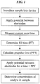
- the steps illustrated in FIG. 1 can be used to determine the concentration of an analyte in a sample.
- a sample is first introduced into the device.
- Any type of sample analyzing devices can be used in conjunction with at least some of the systems and methods disclosed herein. These devices can include, by way of non-limiting example, electrochemical cells, electrochemical sensors, glucose sensors, glucose meters, hemoglobin sensors, antioxidant sensors, biosensors, and immunosensors.
- One exemplary embodiment of a sample analyzing device is an electrochemical sensor.
- the electrochemical sensor can include at least two electrodes.
- the at least two electrodes can be configured in any way, for example, the electrodes can be on the same plane or on different planes.
- a sample can be introduced into the electrochemical cell.
- the introduction of a sample may be detected by an automatic technique in which the meter monitors a change in voltage, current, or capacitance, a change which indicates that sample has been dosed into the sample reaction chamber.
- the physiological sample may be detected by a manual technique in which the user visually observes the filling of the sample reaction chamber and initiates the test by pressing a button.
- an optical detector in the meter can sense the dosing of the sample. The time taken by the sample to fill the reaction chamber can likewise be measured by any number of similar techniques.
- the electrodes can be configured such that when a sample is introduced into the sensor, the second electrode is contacted prior to or simultaneous with the first electrode as the sample fills the sensor.
- the first electrode is limiting in the current it can sustain relative to the voltage applied to the second electrode.
- the first electrode can therefore limit the current flowing in the electrochemical sensor.
- a potential Prior to, simultaneous with, or immediately after the sample contacts the first electrode, a potential can be applied between the electrodes such that when the first and second electrodes are bridged by the sample liquid a current flows between them.
- the current versus time response during the sensor filling can be used to determine the point at which the sensor is adequately filled. For example, adequate filling can mean that sufficient liquid has filled the sensor to entirely cover at least the first electrode.
- the current versus time response can be a discontinuity in the rate of change of current with time, such as an increased drop in current or a decreased rate of increase.
- a discontinuity in the rate of change of current with time such as an increased drop in current or a decreased rate of increase.
- a potential of between about +10 mV to about +30 mV can be applied between the first and second electrodes of an electrochemical cell for a period of time, e.g., about 1000 ms, as a sample introduced into the device fills the cell.
- a potential of about +20 mV can be applied between the first and second electrodes as a sample introduced into the device fills the cell.
- the current flowing between the electrodes can be measured at predetermined intervals during this time. For example, the current can be measured every 2 milliseconds ("ms") and the average current can be stored every 10 ms.
- the current data can then be analyzed, by a control unit, for example.
- control unit can include a microprocessor.
- the analysis of the current data measured over the approximately 1000 ms, during which the sample fills the device can include a determination of the latest time at which the current decreases by a predetermined amount. This time can be used as the fill time (FT) of the sample.
- FT fill time
- the latest time at which the current decreases by more than 0.4 micro-Ampere (" ⁇ A") over a 40 ms interval can be used to determine the time at which the sample has filled the cell.
- the step of determining current drop time can include calculating a difference between in at least two current values where the difference is greater than or less than a predetermined threshold value.
- a predetermined threshold value can be employed. For example, when the area of the working electrode is about 4.2 square millimetres and hematocrits as high as about 75% are being assayed, the predetermined threshold value can be in the range of about 0.4 micramperes over about a 40 ms time period.
- the predetermined threshold value can be in the range of about 0.7 microamperes to about 0.9 micramperes over about a 50 ms time period.
- the step of determining current drop time can include calculating an inflection point in the measured current as a function of time.
- detecting the presence of a sample can include applying an electric potential between the two electrodes, and measuring a change in current values that is greater than or less than a predetermined threshold value.
- a predetermined threshold value can be employed. For example, when the area of the working electrode is about 4.2 square millimeters, the predetermined threshold value can be in the range of about 3 microamperes.
- detecting the presence of a sample can include applying a generally constant current between the two electrodes, and measuring a change in an electric potential that is greater than or less than a predetermined threshold.
- the predetermined threshold value can be in the range of about 200 mV. In other exemplary embodiment, the threshold value can be about 400 mV.
- a first electric potential having a first polarity
- a first electric potential can be applied between a first and second electrode and a resulting current measured as a function of time.
- This first electric potential can be referred to, for example, as a prepulse.
- the length of time that a prepulse can be applied can be about 5 seconds.
- the fill time (FT) of the sample which can be determined using any of the techniques discussed above, can be used to calculate the length of time that a prepulse can be applied. This time period can be referred to, for example, as a prepulse time (PPT).
- PPT prepulse time
- the calculation of prepulse time can allow for longer prepulse times for samples that take longer to fill the sensor.
- the prepulse time can be set according to the following exemplary parameters.
- the fill time can be set to 300 ms.
- This calculation allows the prepulse time (PPT) to be adjusted to allow for longer reaction times for samples that take more than a predetermined amount of time, e.g., about 300 ms, to fill the sensor.
- a maximum prepulse time can be set if the fill time is longer than a predetermined length of time. For example, in one embodiment, if the fill time is greater than about 500 ms, e.g., about 515 ms, the prepulse time (PPT) can be set equal to 5000 ms.
- the minimum PPT (for fill times less than about 300 ms) is 3000 ms and the maximum PPT (for fill times greater than about 500 ms, e.g., about 515 ms) is about 5000 ms.
- the calculation of prepulse time can be adjusted so as to take into account other properties and requirements of a particular sample or analyte.
- the variables and constants in the equation shown above for calculation of prepulse time can be adjusted so as to provide alternate maximum and minimum prepulse times, or combinations thereof.
- a potential can be applied between the electrodes of the cell for a time equal to the prepulse time (PPT) and a resulting current measured as a function of time. At least a portion of the data (current as a function of time) provides a first time-current transient.
- the first electrical potential can be sufficiently negative with respect to the second electrode such that second electrode functions as the working electrode in which a limiting oxidation current is measured.
- a second electric potential can be applied between the first and second electrodes for a second time interval. The second electrical potential causes a current that is measured as a function of time to produce a second time-current transient.
- the second potential has a second polarity, which is opposite to the first polarity.
- the second potential can be sufficiently positive with respect to second electrode such that first electrode functions as the working electrode in which a limiting oxidation current is measured.
- the first electric potential and second electrical potential can range from about -0.6 V to about +0.6 V.
- the time interval of the time-current transients can, in one embodiment, can be in the range of about 1 second to 10 seconds, and preferably in the range of about 1 to 5 seconds. In another embodiment, a sum of the first time interval and the second time interval is less than about 5 seconds. It should also be noted that the first time interval does not have to be the same as the second time interval.
- the second electric potential is applied immediately following the application of the first electric potential.
- a delay or open circuit potential is introduced in between the first electric potential and the second electric potential.
- a delay is introduced after physiological sample is detected in the sample reaction chamber, but before the application of the first electric potential. The delay can be in the range of about 0.01 and about 3 seconds, preferably from about 0.05 to about 1 second and most preferably from about 0.5 to about 0.9 seconds.
- a first test potential E 1 can be applied between the electrodes for a first test potential time T 1 , e.g., PPT milliseconds. For example, a potential of+300 mV can be applied.
- a second test potential E 2 can be applied between the electrodes for a second test potential time interval T 2 , e.g., -300 mV for 1000 ms.
- the cell current as a function of time can be measured, herein called a time current transient or a current transient and referred to as i a ( t ), during first test potential time interval T 1 , and as i b ( t ) during the second test potential time interval T 2 .
- the current as a function of time can be measured every 10 ms with the average current stored every 50 ms.
- At least a portion of the data from the first and second potentials (current as a function of time) can provide first and second time-current transients.
- the concentration of an analyte in the sample can then be determined from the current data using any number of algorithms.
- analyte concentration can be calculated using the algorithm as shown in Equation (Eq.) 1.
- G i r i l p ai 2 ⁇ zgr
- G is the analyte concentration
- the terms i l , i r , and i 2 are current values and the terms p, zgr, and a are empirically derived calibration constants.
- p may range from about 0.2 to about 4, and preferably from about 0.1 to about 1.
- the calibration factor a can be used to account for possible variations in the dimensions of the electrochemical cell. Variations in the dimensions of the electrochemical cell can cause a proportional shift in the magnitude of the measured current. Under certain circumstances, manufacturing processes can cause the electrode area to vary from one lot of test strips to another lot of test strips. Calculating a calibration factor a for each lot of test strips helps to compensate for variations in electrode area and the height of the cell. The term a can be calculated during the calibration process of a test strip lot.
- a calibration factor zgr is used to account for variations in the background.
- a presence of an oxidizable species within the reagent layer of the cell before the addition of a sample may contribute to a background signal.
- ferrocyanide e.g., reduced mediator
- the reagent layer were to contain a small amount of ferrocyanide (e.g., reduced mediator) before the sample was added to the test strip, then there would be an increase in the measured test current which would not be ascribed to the analyte concentration. Because this would cause a constant bias in the overall measured test current for a particular lot of test strips, this bias can be corrected for using the calibration factor Z. Similar to the terms p and a, Z can also be calculated during the calibration process. Exemplary methods for calibrating strip lots are described in U.S. Patent No. 6,780,645 .
- p can be 0.51
- a can be 0.2
- zgr can be 5. While the method disclosed herein is described with the use of calibration factors, p , a, and zgr, one skilled in the art will appreciate that their use is not required.
- glucose concentration could be calculated without p , a, and/or Z (in Eq. 1 p and/or a could be set equal to one and zgr could be set equal to zero).
- Eq. 1 can be found in a pending U.S. Application No. 11/240,797 which was filed on September 30, 2005 and entitled "Method and Apparatus for Rapid Electrochemical Analysis,".
- Current value i r can be calculated from the second current transient and current value i l can be calculated from the first current transient. All current values (e.g. i r , i l , and i 2 ) stated in Eq. 1 and in subsequent equations can use the absolute value of the current.
- Current values i r , i l can be, in some embodiments, an integral of current values over a time interval of a current transient, a summation of current values over a time interval of a current transient, or an average or single current value of a current transient multiplied by a time interval of the current transient. For the summation of current values, a range of consecutive current measurement can be summed together from only two current values or to all of the current values. Current value i 2 can be calculated as discussed below.
- i l may be the average current from 1.4 to 4 seconds of a 5 second long period and i r may be the average current from 4.4 to 5 seconds of a 5 second long period, as shown in Eq. 2a and 3a, below.
- i l may be the sum of currents from 3.9 to 4 seconds of a 5 second long period and i r may be the sum of currents from 4.25 to 5 seconds of a 5 second long period, as shown in Eq. 2b and 3b, below.
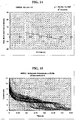
- a magnitude of current for the first current transient can be described as a function of time by Eq. 4.
- i ss is the steady-state current following the application of first test potential E 1
- D is the diffusion coefficient of the mediator
- L is the thickness of the spacer.
- t refers to the time elapsed after first test potential E 1 was applied.
- a magnitude of current for the second current transient can be described as a function of time by Eq. 5.
- Eq. 5 There is a factor of two difference for the exponential term in Eq. 5 as compared to the exponential term in Eq. 4 because the second current transient is generated from the second test potential E 2 , which was opposite in polarity to the first test potential E 1 , and was applied immediately after the first test potential E 1 . It should be noted that in Eq. 5, t refers to the time elapsed after second test potential E 2 was applied.
- a peak current for first test potential time interval T 1 can be denoted as i pa and a peak current for second test potential time interval T 2 can be denoted as i pb . If both first peak current i pa and second peak current i pb were measured at the same short time after the application of first test potential E 1 and second test potential E 2 respectively, for example 0.1 seconds, Eq. 4 can be subtracted from Eq. 5 to yield Eq. 6.
- i pb ⁇ 2 i pa ⁇ i ss
- i pb can be used with i pa together to determine a correction factor.
- i pb can be used with i pa in a mathematical function to determine a corrected current which is proportional to glucose and less sensitive to interferents.
- Eq. 7 was derived to calculate a current i 4 which is proportional to glucose and has a relative fraction of current removed that is ascribed to interferents.
- i 2 i r i pb ⁇ 2 i pa + i ss i pb + i ss
- i ss was added to both the numerator and denominator to allow the numerator to approach zero when no glucose is present.
- the term i ss may be estimated using Equation 8A, for currents at times greater than a minimum time, where a suitable minimum time can be estimated from Equation 8B.
- the current value, i 2 can be calculated according to Eq. 9.
- i 2 i r i 4.1 ⁇ 2 ⁇ i 1.1 + i ss i 4.1 + i ss
- Eq. 1 can enable accurate measurements of analyte concentration in the presence of interferents.
- an estimate of a level of haematocrit can be determined without reference to an associated analyte concentration.
- haematocrit levels of a drop of blood can be determined from current values and an analyte concentration.
- the value of the analyte concentration (G) can be corrected in view of the haematocrit level, e.g., using Eq. 11A and 11B.
- G ′ G + Corr for G ⁇ 100 mg / dL
- G ′ G + 1 + Corr / 100 for G ⁇ 100 mg / dL
- Corr ⁇ 0.2 H ⁇ 50 sin ⁇ G / 180 for G ⁇ 180 mg / dL
- Corr ⁇ 0.5 H ⁇ 50 sin ⁇ G / 180 for 180 ⁇ G ⁇ 270 mg / dL
- Corr + 0.5 H ⁇ 50 for G > 270 mg / dL where the range of Corr is restricted to 0 to -5 for G ⁇ 180, and 0 to 5 for G ⁇ 180.
- the value of the analyte concentration (G) can be corrected in view of the fill time without deriving an estimate of the haematocrit (H), e.g., using Eq. 14A (when G ⁇ 100 mg/dL) and 14B (when G ⁇ 100 mg/dL) in conjunction with Eqs. 15A, 15B, and 15C.
- G ′ G + Corr for G ⁇ 100 mg / dL
- G ′ G + 1 + Corr / 100 for G ⁇ 100 mg / dL
- the threshold value Th 1 can be about 0.2 seconds and the threshold value Th 2 can be about 0.4 seconds.
- the threshold value Th 2 can be about 0.4 seconds.
- the viscosity of the sample can affect the fill time of the sample.
- the sample can take more than about 0.4 seconds to fill the sensor.
- the correction factor can be restricted to a maximum of about 10 mg/dL plasma glucose or about 10% of the signal.
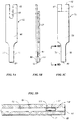
- the glucose sensor can include an electrochemical cell, such as the cell illustrated in FIGS. 2A and 2B .
- the cell can include a thin strip membrane 201 having upper and lower surfaces 202, 203, and can also include a cell zone 204 defined between a working electrode 206 disposed on the lower surface 203 and a counter/reference electrode 205 disposed on the upper surface 202.
- the membrane thickness can be selected to achieve a desired result, such as having the reaction products from a counter electrode arrive at a working electrode.
- the membrane thickness can be selected so that the electrodes are separated by a distance t, which can be sufficiently close such that the products of electrochemical reaction at the counter electrode can migrate to the working electrode during the time of the test and a steady state diffusion profile can be substantially achieved.
- t can be less than approximately 500 micrometers, alternatively in the range of about 10 micrometers to about 400 micrometers, and more particularly in the range of about 80 micrometers to about 200 micrometers.
- a spacing between the electrodes can be selected such that the reaction products from a counter electrode arrive at a working electrode before the end of the assay.
- the electrodes can also have a variety of configurations.
- the electrodes can be planar.
- the electrodes 205, 206 are facing each other and are substantially opposed, in other embodiments the electrodes can just be facing each other, they can be substantially opposed to each other, or they can have a side-by-side configuration in which the electrodes are positioned approximately in the same plane. Examples of different electrode configurations can be found at least in U.S. Patent No. 7,431,820 of Hodges , entitled "Electrochemical Cell,” and filed on October 14, 2003.
- a sample deposition or "target" area 207 can be defined on the upper surface 202 of the membrane 201 and can be spaced at a distance greater than the membrane thickness from the cell zone 204.
- the membrane 201 can have a diffusion zone 208 that can extend between the target area 207 and the cell zone 204.
- a suitable reagent can include a redox mediator M, an enzyme E , and a pH buffer B , each of which can be contained within the cell zone 204 of the membrane and/or between the cell zone 204 and the target area 207.
- the reagent can also include stabilizers and the like.
- a drop of blood can be placed on the target zone 207, and the blood components can wick towards the cell zone 204.
- Each of electrodes 205, 206 can have a predefined area.
- the cell zone 204 can defined by edges 209, 210, 211 of the membrane, which can correspond with edges of the electrodes 205, 206 and by leading (with respect to the target area 207) edges 212, 213 of the electrodes.
- the electrodes can be about 600 angstrom thick and can be from about 1 to about 5 mm wide although a variety of other dimensions and parameters can be used without departing from the scope of the present invention.
- both sides of the membrane can be covered with the exception of the target area 207 by laminating layers 214 (omitted from plan views) which can serve to prevent evaporation of water from the sample and to provide mechanical robustness to the apparatus. Evaporation of water is believed to be undesirable as it concentrates the sample, allows the electrodes to dry out, and allows the solution to cool, affecting the diffusion coefficient and slowing the enzyme kinetics, although diffusion coefficient can be estimated as above.
- a hollow electrochemical cell for use with the systems and methods disclosed herein is provided.
- the electrodes 305, 306 can be supported by spaced apart polymer walls 330 to define a hollow cell.
- An opening 331 can be provided on one side of the cell whereby a sample can be admitted into the cavity 332.
- a membrane is not used, although in some embodiments a membrane can be included.
- the electrodes can have a variety of configurations, at least as discussed above. By way of non-limiting example, the electrodes can be spaced apart by less than about 500 micrometers, preferably in the range of about 10 or about 20 micrometers to about 400 micrometers, and more preferably in a range of about 80 micrometers to about 200 micrometers.
- the effective cell volume can be about 1.5 microliters or less.
- electrochemical cells of FIGS. 2A, 2B, and 3 can be used in conjunction with the meters, control units, and other components and steps of the devices, systems, and methods disclosed herein. Further disclosures related to the electrochemical cells of FIGS. 2A, 2B, and 3 are found in U.S. Patent No. 6,284,125 of Hodges et al. , entitled "Electrochemical cell” and filed on April 17, 1998.
- electrochemical cells used in conjunction with the present disclosures can have two electrode pairs.
- the electrode pairs can include any combination of working, counter, counter/reference, and separate reference electrodes.
- the sensor can be in the form of a form of a test strip 62 including an elongate body 59 that extends along a longitudinal axis L from a proximal end 80 to a distal end 82 and having lateral edges 56, 58.
- Body 59 can include a proximal sample reaction chamber 61 that contains electrodes 164, 166 and a reagent 72.
- Test strip body 59 can further include distally positioned electrical contacts 63, 67 for electrically communicating with a test meter (not illustrated).
- test strip 62 is formed from multiple layers including a first electrically conductive layer 66, a spacer 60, a second electrically conductive layer 64.
- First electrically conductive layer 66 and/or second electrically conductive layer 64 can be formed from a variety a conductive materials that are, in one embodiment, positioned on an insulating sheet (not shown).
- Spacer layer 60 can be formed from a variety of electrically insulating materials and can include, or be formed from, an adhesive.
- additional electrically conductive or insulative layers could be used to form test strip body 59.
- proximal sample reaction chamber 61 can be defined by first electrically conductive layer 66, second electrically conductive layer 64, and spacer layer 60.
- reaction chamber 61 can also include a reagent 72 and first and second electrodes 166, 164.
- a cutout area 68 in spacer 60 can expose a portion of second electrically conductive layer 64 and first electrically conductive layer 66, and thereby defines first electrode 166 and second electrode 164, respectively.
- Reagent 72 can be in the form of a layer positioned on first electrode 166.
- reaction chamber 61 is adapted for analyzing small volume samples.
- sample reaction chamber 61 can have a volume ranging from about 0.1 microliters to about 5 microliters, preferably about 0.2 to about 3 microliters, and more preferably about 0.3 microliters to about 1 microliter.
- the electrodes are preferably closely spaced.
- the height of spacer 60 can be in the range of about 1 micron to about 500 microns, preferably in the range of about 10 microns and about 400 microns, and more preferably in the range of about 40 microns and about 200 microns.
- test strip body 59 can include cut-away portions 51, 52 such that the lateral width of reaction chamber 61 is smaller than the full width (widest width) of test strip body 59. Cut-away portions 51, 52 can also facilitate delivery of a sample to reaction chamber 61.
- cut-away portion 51, 52 can have a shape corresponding to a portion of a finger of a user.
- test strip body 59 could include only a single cut-away portion or no cut-away portions.
- test strip body 59 can include at least one sample delivery port for delivery of a sample to reaction chamber 61.
- cutout area 68 can extend transversely to the lateral edges 56, 58 of test strip body 59 to provide two openings 70 for the delivering of physiological fluid to sample reaction chamber 61. Where two openings 70 are present one can act as a sample receiving port for delivery of a fluid sample while the other can act as a vent.
- sample can be delivered to sample reaction chamber 61 using alternative structures including sample receiving ports and/or vents positioned at different locations in test strip body 59, such as, for example, sample receiving ports and/or vents positioned in first and/or second electrically conductive layers 66, 64.
- test strip 62 is adapted to draw sample into reaction chamber 61 via capillary action.
- the dimensions and surface characteristics of reaction chamber 61 and openings 70 can be adapted to produce a capillary force when a liquid sample (e.g., whole blood) is brought into contact with one of openings 70.
- a liquid sample e.g., whole blood
- reaction chamber 61 can include additional structures to assist with/create capillary forces such as, for example, beads, a porous membrane, and/or other fillers.
- a reagent such as reagent 72
- the composition of reagent 72 can vary depending on the intended analyte and the expected form of the sample.
- reagent 72 includes at least a mediator and an enzyme and is deposited onto first electrode 166.
- mediators and/or enzymes are within the scope of the present disclosure.
- suitable mediators include ferricyanide, ferrocene, ferrocene derivatives, osmium bipyridyl complexes, ruthenium (III) hexamine, and quinone derivatives.
- Suitable enzymes include glucose oxidase, glucose dehydrogenase (GDH) based on pyrroloquinoline quinone (PQQ) co-factor,GDH based on nicotinamide adenine dinucleotide co-factor, and flavine-adenine dinucleotide (FAD) based GDH (FAD-GDH) .
- GDH glucose dehydrogenase
- PQQ pyrroloquinoline quinone
- FAD flavine-adenine dinucleotide
- FAD-GDH flavine-adenine dinucleotide
- body 59 can include connection tracks that electrically connect first and second electrodes 166, 164 with distal electrical contacts 63, 67.
- first electrically conductive layer 66 includes a first connection track 76 that electrically connects first electrode 166 with a first electrical contact 67.
- second electrically conductive layer 64 can include a second connection track 78 that connects the second electrode 164 with a second electrical contact 63 ( FIG. 5A ).
- First and second electrically conductive layers can also define first and second electrical contacts 67, 63 that facilitate electrical contact of test strip 62 with a test meter.
- a portion of first electrically conductive layer 66 extends distally from the distal end of spacer layer 60 and second electrically conductive layer 64 to define first electrical contact 67.
- Second electrical contact can be defined by a U-shaped notch 65 in the first electrically conductive layer 66 which exposes a portion of second electrically conductive layer 64.
- test strip 62 can include a variety of alternative electrical contact configurations for electrically connecting to a test meter.
- U.S. Pat. No. 6,379,513 discloses electrochemical cell connection structures.
- FIGS. 4A through 5D can be used in conjunction with the meters, control units, and other components and steps of the devices, systems, and methods disclosed herein. Further disclosures related to the electrochemical cells of FIGS. 4A through 5D are found in U.S. Patent Application Serial No. 11/278,341 of Chatelier et al. , entitled “Methods And Apparatus For Analyzing A Sample In The Presence Of Interferents,” and filed on March 31.
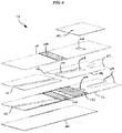
- FIG. 6 Another exemplary embodiment of a sample analyzing device for use in conjunction with at least some of the methods disclosed herein, an immunosensor 110, is illustrated in FIG. 6 and is described in U.S. Patent Application Serial No. 12/570,268 of Chatelier et al. , entitled “Adhesive Compositions for Use in an Immunosensor” and filed on September 30, 2009.
- a plurality of chambers can be formed within the immunosensor, including a fill chamber, by which a sample can be introduced into the immunosensor, a reaction chamber, by which a sample can be reacted with one or more desired materials, and a detection chamber, by which a concentration of a particular component of the sample can be determined.
- the immunosensor can also include a vent hole to allow air to enter and escape the immunosensor as desired, and first and second sealing components to selectively seal first and second sides of the vent hole.
- the first sealing component can also form a wall of the fill chamber.
- the immunosensor 110 includes a lower electrode 112 having two liquid reagents 130, 132 striped onto it.
- the lower electrode 112 can be formed using any number of techniques used to form electrodes, but in one embodiment a polyethylene tetraphthalate (PET) sheet that is filled with barium sulphate is sputter-coated with gold.
- PET polyethylene tetraphthalate
- Other non-limiting example of forming an electrode are disclosed in U.S. Patent No. 6,521,110 of Hodges et al. , entitled “Electrochemical Cell” and filed on November 10, 2000.
- the liquid reagents 130, 132 can have a number of different compositions.
- the first liquid reagent 130 includes an antibody conjugated to an enzyme, such as GDH-PQQ, in a buffer that contains sucrose, as well as a poloxamer, such as Pluronics ® block copolymers, an anticoagulant, such as citraconate, and calcium ions.
- the second liquid reagent 132 includes a mixture of ferricyanide, glucose, and a second mediator, such as phenazine ethosulfate, in an acidic buffer, such as a dilute citraconic acid solution.
- the first and second liquid reagents 130, 132 can be dried onto the lower electrode 112.
- a number of techniques can be used to dry the reagents 130, 132, but in one embodiment, following the striping of the reagents 130, 132 on the lower electrode 112, one or more infrared dryers can be applied to the reagents 130, 132. One or more air dryers can also be used, for example, subsequent to the infrared dryers.
- References to a first reagent and a first liquid reagent and a second reagent and a second liquid reagent herein are used interchangeably and are not necessarily an indication that the reagents are in their liquid or dried form at a given time for a particular embodiment.
- an anticoagulant can be associated with either or both of the first liquid reagent 130 and the second liquid reagent 132.
- a line can be formed in the sputter-coated gold between the reagents 130, 132 such that an edge of reagent 132 is very close to, or touches, the line.
- the line can be applied using laser ablation or with a sharp metal edge.
- the line can be applied before the reagents 130, 132 are striped on the electrode.
- the line can be designed to electrically insulate the section of the lower electrode 112 under the detection chamber from the section that will be under the reaction chamber. This can provide a better definition of an area of the working electrode during the electrochemical assay.
- the immunosensor 110 can also include an upper electrode 114 having one or more magnetic beads 134 containing surface-bound antigens thereon.
- the antigens can be configured to react with the antibody disposed on the lower electrode 112 and the sample within a reaction chamber 118, as described in further detail below.
- the components disposed on the lower electrode 112 and on the upper electrode 114 can be interchangeable.
- the lower electrode 112 can include one or more magnetic beads 134 and the upper electrode 114 can include two liquid reagents 130, 132 striped onto it.
- the length of the electrode 112 forms the length of the entire body of the immunosensor 110
- the electrode can be only a portion of a layer of an immunosensor that serves as the lower or upper electrode or multiple electrodes can be disposed on a single layer of an immunosensor.
- each of the lower and upper electrodes can serve as the working electrode and the counter or counter/reference electrode at different stages.
- the lower electrode is considered the working electrode and the upper electrode the counter or counter/reference electrode.
- a separator 116 disposed between the lower and upper electrodes 112, 114 can have a variety of shapes and sizes, but it generally is configured to desirably engage the lower and upper electrodes 112, 114 to form the immunosensor 110.
- the separator 116 includes adhesive on both sides.
- the separator 116 can further include a release liner on each side of the two sides of the separator 116.
- the separator 116 can be cut in a manner that forms at least two cavities.
- a first cavity can be formed to serve as a reaction chamber 118 and a second cavity can be formed to serve as a detection chamber 120.
- the separator 116 can be kiss-cut such that the reaction chamber 118 is aligned with the electrodes 112, 114 to allow an antigen-antibody reaction therein while the detection chamber 120 is aligned with the electrodes 112, 114 to allow for the electrochemical determination of ferrocyanide therein.
- the separator 116 can be placed on the lower electrode 112 in a manner that allows the magnetic beads 134 of the upper electrode 114 and the first reagent 130 of the lower electrode 112 to be at least partially disposed in the reaction chamber 118 and the ferricyanide-glucose combination of the second reagent 132 of the lower electrode 112 to be at least partially disposed in the detection chamber 120. It can be advantageous to include an anticoagulant in each of the first and second liquid reagents 130, 132 so that an anticoagulant is associated with each of the reaction and detection chambers 118, 120.
- the combination of one of the upper and lower electrodes 112, 114 and the separator 116 can be laminated together to form a bi-laminate, while in other embodiments the combination of each of the lower electrode 112, the upper electrode 114, and the separator 116 can be laminated together to form a tri-laminate. Alternatively, additional layers may also be added.
- a fill chamber 122 can be formed by punching a hole into one of the lower and upper electrodes 112, 114 and the separator 116.
- the fill chamber is formed by punching a hole in the lower electrode 112 and the separator 116 such that the hole in the lower electrode 112 overlaps the reaction chamber 118.
- the fill chamber 122 can be a distance apart from the detection chamber 120.
- Such a configuration allows a sample to enter the immunosensor 110 through the fill chamber 122 and flow into the reaction chamber 118 to be reacted, for example with the first liquid reagent 130 that includes the antibody conjugated to an enzyme in a buffer on the first electrode 112 and the magnetic beads 134 striped on the upper electrode 114, without entering the detection chamber 120.
- the sample Once the sample has been reacted, it can then flow into the detection chamber 120 for interaction with the second liquid reagent 132, for example the mixture of ferricyanide, glucose, and the second mediator in an acidic buffer.
- a vent 124 can be formed by punching a hole through each of the two electrodes 112, 114 and the separator 116 such that the vent 124 extends through the entirety of the immunosensor 110.
- the hole can be formed in a suitable manner, such as, for example, drilled or punched in a number of different locations, but in one exemplary embodiment it can overlap a region of the detection chamber 120 that is spaced apart from the reaction chamber 118.
- the vent 124 can be sealed in a number of different manners.
- a first sealing component 140 is located on the lower electrode 112 to seal a first side of the vent 124 and a second sealing component 142 is located on the upper electrode 114 to seal a second side of the vent 124.
- the sealing components can be made of and/or include any number of materials.
- either or both of the sealing components can be hydrophilic adhesive tape or Scotch® tape. Adhesive sides of the sealing components can face the immunosensor 110. As shown, not only can the first sealing component 140 form a seal for the vent 124, but it can also form a wall for the fill chamber 122 so that the sample can be contained therein.
- Properties incorporated onto the adhesive side of the first sealing component 140 can be associated with the fill chamber 122.
- the fill chamber can remain well-wet when a sample is disposed therein.
- the sealing components 140, 142 can be selectively associated and disassociated with the immunosensor 110 to provide venting and/or sealing for the immunosensor 110 and the components disposed therein as desired.
- Adhesives can generally be used in the construction of the immunosensor.
- Non-limiting examples of ways in which adhesives can be incorporated into immunosensors and other sample analyzing devices of the present disclosure can be found in U.S. Patent Application Serial No. 12/570,268 of Chatelier et al. , entitled “Adhesive Compositions for Use in an Immunosensor” and filed on September 30, 2009.
- the immunosensor 110 can be configured to be placed into a meter that is configured to apply a potential to the electrodes 112, 114 and measure a current that results from the application of the potential.
- the immunosensor includes one or more tabs 117 for engaging a meter.
- Other features can also be used to engage the immunosensor 110 with a meter.
- the meter can include a number of different features.
- the meter can include a magnet that is configured to maintain certain components of the immunosensor 110 in one chamber while other components flow to the other.
- the magnet of the meter is located such that, upon placing the immunosensor 110 in the meter, the magnet is disposed below the reaction chamber 118. This can allow the magnet to assist in holding back any magnetic beads 134, and more particularly any antibody-enzyme conjugate that is bound to the beads 134, from flowing into the detection chamber 120.
- An alternate feature of the meter includes a heating element.
- a heating element can help speed up the reaction rate and help the sample flow through the immunosensor 110 in a desired manner by reducing the viscosity.
- a heating element can also allow one or more chambers and/or a sample disposed therein to be heated to a predetermined temperature. Heating to a predetermined temperature can help provide accuracy, for example, by diminishing or removing the effects of temperature change as reactions occur.
- a piercing instrument can also be associated with the meter.
- the piercing instrument can be configured to pierce at least one of the first and second sealing components at a desired time so that air can flow out of the vent hole and liquid can flow from the reaction chamber into the detection chamber.
- the immunosensor 110 can also be configured to be associated with a control unit.
- the control unit can be configured to perform a variety of functions.
- the control unit is capable of measuring a fill time of a sample when it is introduced to the device.
- the control unit can be configured to determine a haematocrit value of a blood sample.
- the control unit is configured to calculate a concentration of an analyte in the sample in view of the fill time.
- the control unit can include a number of different features, depending, at least in part, on the functionality desired and the method by which the system is designed to measure the fill time..
- the control unit can also measure other aspects of the system.
- the control unit can be configured to measure a temperature of one or more chambers of the immunosensor. It can also be configured to measure a temperature of the sample, a color of the sample, or a variety of other characteristics and/or properties of the sample and/or the system.
- the control unit can be configured to communicate the results of the fill time determination, the results of the analyte concentration determination, and/or the haematocrit measurement to outside equipment. This can be accomplished in any number of ways.
- the control unit can be hardwired to a microprocessor and/or a display device.
- the control unit can be configured to wirelessly transmit data from the control unit to a microprocessor and/or a display device.
- the immunosensor or the meter can be configured to measure a temperature of one or more chambers of the immunosensor, measure or infer the temperature of a sample, or measure, determine, or infer a variety of other characteristics and/or properties of the sample and/or the system.
- a control unit can be interchanged and selectively combined in a single control unit.
- a control unit can both determine a fill time and measure a temperature of a chamber.
- multiple control units can be used together to perform various functions, based at least in part on the configurations of the various control units and the desired functions to be performed.
- the system included a sensor with two opposed electrodes, with reagents designed to react with the sample dried on one electrode.
- a plurality of samples was provided for analysis to test the performance of the systems, devices, and methods disclosed herein.
- the samples were blood samples that contained three different levels of haematocrit, which were known so comparisons of the test results could be compared to the actual results to determine the accuracy of the systems, devices, and methods.
- the four levels of haematocrit were approximately 20%, 60%, and 75%. Testing three levels of haematocrit allowed the accuracy of the disclosed systems, devices, and methods to be confirmed over a broad spectrum of concentration levels.
- the electrode covered with the dried reagent is the second electrode.
- the first and second electrodes cover the entire area of the chamber to be filled with liquid sample.
- Samples were introduced into the sensor. While the introduction of samples into the sensor could have been accomplished in a variety of manners, in this example each sample was admitted individually by way of capillary action into the fill chamber. As soon as the blood started to enter the detection chamber, a 300 mV potential was applied to the electrodes by way of the meter for approximately four seconds. Alternatively, the voltage could have been applied prior to or while the blood was arriving in the detection chamber.
- FIG. 7 A plot of the current versus time transient resulting from this example is illustrated in FIG. 7 . As shown in the FIG.
- the line showing the time-current transient obtained with 75% haematocrit blood is relatively flat from about 0.1 to about 0.5 seconds since the filling process increases the area of the first electrode (which would tend to increase the current) and at the same time there is electrochemical depletion of electroactive species at the first electrode (which would tend to decrease the current).
- These two processes are approximately matched while the sensor is filling with blood. After fill is complete (at approximately 0.5 s) the first process is over and the second process dominates so that the current drops abruptly. The latest time at which the current decreases sharply is taken as the fill time.
- a second type of sensor was constructed which included two opposed electrodes with reagents designed to react with the sample dried on one electrode.
- the electrode with the dried reagent was the first electrode and was configured such that it did not cover the entire area of the liquid filled chamber whereas the second electrode was configured such that it covered a wider area of the liquid filled chamber and was contacted with liquid prior to the first electrode being contacted with liquid.
- the early part of each trace corresponds to the period during which the filling process increases the area of the working electrode and hence increases the current.
- the electrochemical depletion of electroactive species tends to decrease the current at the time indicated by the arrows in the figure.
- the time at which the current decreases sharply is taken as the fill time.
- the different configuration of the sensors leads to a different dependence of fill time on haematocrit.
- variable prepulse times in an electrochemical system is demonstrated by the following example.
- a potentiostat meter was constructed which was capable of using the fill time information to vary the prepulse time using the methods discussed above.
- An initial test of the new meters was performed using heparinised capillary blood. The natural haematocrit and glucose were tested, and then plasma and 77% blood were tested at the natural or spiked glucose levels. Strips were tested on the original (fixed time) meters and on the meters which incorporated the variable prepulse time algorithm disclosed above. The data were analyzed using the algorithm discussed above.
- FIG. 9 shows that the 77% haematocrit blood gave negative biases (-19 to -28%) when tested with the original (fixed time) meters, but that all points were within 15% of the reference glucose measurement when tested with the variable prepulse time meters.
- An example of a commercially available instrument configured to perform a reference glucose measurement is a Yellow Springs Instrument (YSI) glucose analyzer.
- YSI Yellow Springs Instrument
- Table 1 Parameter Fixed time meters Variable time meters Mean CV (%) 3.6 3.0 Mean bias -9.4 -4.4 Global SD bias 12.0 5.9 % biases within 15% 62 100
- variable time meters outperformed the fixed time meters in terms of accuracy and precision.
- the system included a sample analyzing device, in particular the immunosensor 110 of FIG. 6 , a meter configured to apply a potential, and a control unit configured to determine the initial fill velocity.
- a potential was applied to the electrodes of the immunosensor 110, a level of haematocrit was determined, and then the potential was reversed.
- the concentration of the analyte was subsequently determined in view of the determined level of haematocrit.
- the level of haematocrit was determined in view of a fill time of the sample.
- a plurality of samples was provided for analysis to test the performance of the systems, devices, and methods disclosed herein.
- the samples were blood samples that contained C-reactive proteins, and thus the concentration of the analyte being determined was the concentration of C-reactive proteins.
- the samples contained four different levels of haematocrit, which were known so comparisons of the test results could be compared to the actual results to determine the accuracy of the systems, devices, and methods.
- the four levels of haematocrit were approximately 15%, 49%, 60%, and 72%. Testing four levels of haematocrit allowed the accuracy of the disclosed systems, devices, and methods to be confirmed over a broad spectrum of concentration levels.
- an immunosensor was preheated to approximately 37 °C before a sample was introduced.
- the meter associated with the immunosensor was configured to perform the preheating, although other alternatives could have been used.
- Samples were then introduced into the immunosensor. While the introduction of samples into the immunosensor could have been accomplished in a variety of manners, in the example each sample was admitted individually by way of capillary action into the fill chamber.
- the vent of the immunosensor was accessed by piercing the first sealing component.
- a piercing instrument of the meter was used to perform the piercing action, which in turn allowed the blood to flow from the reaction chamber of the immunosensor into the detection chamber of the immunosensor.
- a 300 mV potential was applied to the electrodes by way of the meter.
- the current versus time transient was used to determine the fill time of the sample according to the methods discussed above.
- a plot of the fill time versus haematocrit percentage from this example is illustrated in FIG. 10 .
- the estimate of the haematocrit according to the methods disclosed herein can be used to express the antigen concentration with respect to plasma rather than whole blood, since this is more acceptable in pathology.
- the first calculation based on the initial current may be the only step that is needed to make that calculation.
- the actual determination of the haematocrit level can be determined as quickly as the initial current can be calculated.
- the level of haematocrit can be determined following the first 50 milliseconds.
- An exemplary algorithm for correcting an analyte measurement based on fill time of a sample without further derivation of and correction for hematocrit is demonstrated by the following example.
- a sensor which contained the enzyme FAD-GDH, instead of GDH-PQQ was tested.
- a blood sample containing glucose was applied to the sensor and the potential waveform shown in FIG. 11 was applied.
- a fill time of the sample was determined during the application of the first potential to the sensor (E1, which was about +20 mV in this example) for about 1 second.
- the fill time was determined to be the period of time from the first detection of sample in the sensor until the time at which the maximum value of the rate of change of the current transient during application of the first potential was measured, i.e., the maximum value of i(t) - i(t + dt).
- the maximum value of i(t) - i(t + dt), i.e., the sharpest drop in current, corresponds to the time at which a sufficient volume of the sample has filled the sensor for the analyte measurement to be conducted.
- the fill time was not assessed during the approximately first 0.15 seconds following sample detection, since the initial signal is a combination of the rapid current decrease due to the consumption of antioxidant species near the anode and the slower current increase which accompanies filling of the sensor. When these two rates are matched then a pseudo steady state current is achieved and there is little change in current while the rest of the sensor fills with blood. For this reason, the earliest fill time shown in FIG. 11 is about 0.15 seconds.
- a second test potential E2 of +300 mV was applied for about 3 seconds after which a third test potential E3 of -300 mV was applied.
- Values of i l and i r were calculated using Eqs. 2b and 3b.
- a value of i l was calculated as the sum of currents from 3.9 to 4 seconds of the 5 second long period and a value of i r was calculated as the sum of currents from 4.25 to 5 seconds of the 5 second long period.
- a first glucose concentration in the sample was then calculated using Eq. 1, above.
- the values of p, a and zgr were 0.5796, 0.02722 and 1.8, respectively.
- the first glucose concentration was then corrected in view of the fill time of the sample according to Eqs. 14A, 14B, 15A, 15B, and 15C, above, for which the two threshold values of FT, Th 1 and Th 2 were 0.2 seconds and 0.4 seconds, respectively.
- the results of glucose measurements corrected in view of fill time according to Eqs. 14A, 14B, 15A, 15B, and 15C improved accuracy resulting in a lower bias from reference data.
- FIG. 12 shows that the bias of samples from reference values of analyte concentration was dependent on the fill time of the sample.
- the bias of samples was increasingly negative as fill time increases. In other words, the accuracy of uncorrected values of analyte concentration decreased for samples with longer fill times. Thus, there is a distinct dependence of the bias on the fill time of samples.
- FIG. 13A shows the same data set as shown in FIG. 12 plotted against the hematocrit range of the samples.
- FIG. 13B shows the improvement obtained when the data is corrected in view of fill time according to Eqs. 14A, 14B, 15A, 15B, and 15C, above.
- the global SD bias decreased from 6.2 to 5.7 after the data was corrected for fill time.
- FIG. 14 illustrates a plot of the bias versus fill time data for samples obtained from 311 donors tested using FAD-GDH sensors in a clinical setting according to the algorithms discussed above in Example 5.
- the fill time correction provided a decrease in global SD bias from 5.75 to 5.58.
- the improvement in this clinical data was only modest because most samples filled the sensor in about 0.2 seconds or less, and were this uncorrected by the fill time algorithm.
- FIG. 15 illustrates the current transients obtained when blood with hematocrits in the range of about 15% to about 72% was loaded into sensors.
- FIG. 16 illustrates fill time data calculated from the data of FIG. 15 .
- FIG. 16 shows the raw fill time values as open diamonds, the mean of 5 replicates as filled squares, and ⁇ 1 SD as vertical bars.
- the fill times ranged from about 0.06 seconds to about 0.32 seconds, with higher hematocrit samples filling more slowly.
- the global SD bias decreased from 5.08 to 4.71 after the glucose values were corrected for fill time using the algorithms discussed above in Example 5.
- Non-limiting examples of some of the other types of devices with which the methods disclosed herein can be used are discussed in greater detail in U.S. Patent No. 5,942,102 of Hodges et al. , entitled “Electrochemical Method” and filed on May 7, 1997, U.S. Patent No. 6,174,420 of Hodges et al. , entitled “Electrochemical Cell” and filed on May 18, 1999, U.S. Patent No. 6,379,513 of Chambers et al. , entitled “Sensor Connection Means” and filed on September 20, 1999, U.S. Patent No. 6,475,360 of Hodges et al. , entitled “Heated Electrochemical Cell” and filed on September 11, 2000, U.S. Patent No.
- any number of configurations can be used.
- some configurations that can be used with the present disclosures include sensors having two electrodes facing each other, sensors having two electrodes on the same plane, and sensors having three electrodes, two of which are opposed and two of which are on the same plane. These different configurations can occur in any number of devices, including immunosensors and the other aforementioned devices.
Claims (4)
- Système électrochimique, comprenant :une cellule électrochimique ayant une électrode inférieure (112) et une électrode supérieure (114) ;un dispositif de mesure connecté à la cellule électrochimique de sorte que le dispositif de mesure applique un potentiel entre l'électrode inférieure et l'électrode supérieure de la cellule électrochimique ; etune unité de commande connectée à l'appareil de mesure de sorte que l'unité de commande détermine un temps de remplissage d'un échantillon introduit dans la cellule électrochimique et utilise le temps de remplissage pour calculer une concentration d'un analyte dans l'échantillon,et la cellule électrochimique comprenant un immunocapteur (110), l'immunocapteur comprenant :un premier réactif liquide (130) comprenant un anticorps conjugué à une enzyme dans un tampon, le premier réactif liquide étant rayé sur l'électrode inférieure et séché ;un second réactif liquide (132) comprenant du ferricyanure, un substrat pour l'enzyme et un médiateur électrochimique dans une solution acide diluée, le second réactif liquide étant rayé sur l'électrode inférieure et séché ;des perles magnétiques (134) conjuguées à un antigène, les perles magnétiques étant rayées sur l'électrode supérieure et séchées sur celle-ci ;un séparateur (116) disposé entre les électrodes inférieure et supérieure ;une chambre de réaction (118) formée dans le séparateur et ayant le premier réactif et les perles magnétiques conjuguées à l'antigène disposés dans celle-ci, l'échantillon, l'anticorps et l'antigène étant configurés pour réagir les uns avec les autres dans la chambre de réaction ;une chambre de détection (120) formée dans le séparateur et ayant le second réactif disposé dans celle-ci,une chambre de remplissage (122) formée au moins partiellement dans le séparateur et l'une des électrodes inférieure et supérieure, espacée d'une certaine distance de la chambre de détection et chevauchant au moins une partie de la chambre de réaction ;un évent (124) formé au moins partiellement dans chacun du séparateur, de l'électrode inférieure et de l'électrode supérieure, espacé d'une certaine distance de la chambre de réaction, et chevauchant au moins une partie de la chambre de détection ;un premier composant d'étanchéité (140, 142) ayant un anticoagulant incorporé couplé à l'une des électrodes inférieure et supérieure, disposé sur l'évent, et configuré pour former une paroi de la chambre de remplissage et sceller l'évent ; etun deuxième composant d'étanchéité (140, 142) couplé à l'autre des électrodes inférieure et supérieure, disposé au-dessus de l'évent et configuré pour sceller l'évent.
- Système électrochimique selon la revendication 1, comprenant en outre un élément chauffant configuré pour chauffer au moins une partie de la cellule électrochimique.
- Système électrochimique selon la revendication 1, le premier composant d'étanchéité comprenant un ruban adhésif hydrophile.
- Système électrochimique selon la revendication 1, au moins l'un du capteur immunologique, du dispositif de mesure et de l'unité de commande comprenant une configuration pour mesurer une température de l'échantillon.
Priority Applications (2)
| Application Number | Priority Date | Filing Date | Title |
|---|---|---|---|
| EP17206275.4A EP3349008B1 (fr) | 2009-12-30 | 2010-12-29 | Systèmes, dispositifs et procédés d'amélioration de la précision de biocapteurs à l'aide de temps de remplissage |
| EP17206283.8A EP3349009A1 (fr) | 2009-12-30 | 2010-12-29 | Systèmes, dispositifs et procédés d'amélioration de la précision de biocapteurs à l'aide de temps de remplissage |
Applications Claiming Priority (3)
| Application Number | Priority Date | Filing Date | Title |
|---|---|---|---|
| US12/649,594 US8101065B2 (en) | 2009-12-30 | 2009-12-30 | Systems, devices, and methods for improving accuracy of biosensors using fill time |
| US12/971,777 US8623198B2 (en) | 2009-12-30 | 2010-12-17 | Systems, devices, and methods for improving accuracy of biosensors using fill time |
| EP10252245.5A EP2360477B1 (fr) | 2009-12-30 | 2010-12-29 | Systèmes, dispositifs et procédés pour améliorer la précision de biocapteurs utilisant le temps de remplissage |
Related Parent Applications (2)
| Application Number | Title | Priority Date | Filing Date |
|---|---|---|---|
| EP10252245.5A Division EP2360477B1 (fr) | 2009-12-30 | 2010-12-29 | Systèmes, dispositifs et procédés pour améliorer la précision de biocapteurs utilisant le temps de remplissage |
| EP10252245.5A Division-Into EP2360477B1 (fr) | 2009-12-30 | 2010-12-29 | Systèmes, dispositifs et procédés pour améliorer la précision de biocapteurs utilisant le temps de remplissage |
Related Child Applications (4)
| Application Number | Title | Priority Date | Filing Date |
|---|---|---|---|
| EP17206283.8A Division-Into EP3349009A1 (fr) | 2009-12-30 | 2010-12-29 | Systèmes, dispositifs et procédés d'amélioration de la précision de biocapteurs à l'aide de temps de remplissage |
| EP17206283.8A Division EP3349009A1 (fr) | 2009-12-30 | 2010-12-29 | Systèmes, dispositifs et procédés d'amélioration de la précision de biocapteurs à l'aide de temps de remplissage |
| EP17206275.4A Division-Into EP3349008B1 (fr) | 2009-12-30 | 2010-12-29 | Systèmes, dispositifs et procédés d'amélioration de la précision de biocapteurs à l'aide de temps de remplissage |
| EP17206275.4A Division EP3349008B1 (fr) | 2009-12-30 | 2010-12-29 | Systèmes, dispositifs et procédés d'amélioration de la précision de biocapteurs à l'aide de temps de remplissage |
Publications (2)
| Publication Number | Publication Date |
|---|---|
| EP3182127A1 EP3182127A1 (fr) | 2017-06-21 |
| EP3182127B1 true EP3182127B1 (fr) | 2020-03-18 |
Family
ID=44065616
Family Applications (4)
| Application Number | Title | Priority Date | Filing Date |
|---|---|---|---|
| EP17206275.4A Active EP3349008B1 (fr) | 2009-12-30 | 2010-12-29 | Systèmes, dispositifs et procédés d'amélioration de la précision de biocapteurs à l'aide de temps de remplissage |
| EP16200308.1A Active EP3182127B1 (fr) | 2009-12-30 | 2010-12-29 | Systèmes, dispositifs et procédés d'amélioration de la précision de biocapteurs à l'aide de temps de remplissage |
| EP10252245.5A Not-in-force EP2360477B1 (fr) | 2009-12-30 | 2010-12-29 | Systèmes, dispositifs et procédés pour améliorer la précision de biocapteurs utilisant le temps de remplissage |
| EP17206283.8A Withdrawn EP3349009A1 (fr) | 2009-12-30 | 2010-12-29 | Systèmes, dispositifs et procédés d'amélioration de la précision de biocapteurs à l'aide de temps de remplissage |
Family Applications Before (1)
| Application Number | Title | Priority Date | Filing Date |
|---|---|---|---|
| EP17206275.4A Active EP3349008B1 (fr) | 2009-12-30 | 2010-12-29 | Systèmes, dispositifs et procédés d'amélioration de la précision de biocapteurs à l'aide de temps de remplissage |
Family Applications After (2)
| Application Number | Title | Priority Date | Filing Date |
|---|---|---|---|
| EP10252245.5A Not-in-force EP2360477B1 (fr) | 2009-12-30 | 2010-12-29 | Systèmes, dispositifs et procédés pour améliorer la précision de biocapteurs utilisant le temps de remplissage |
| EP17206283.8A Withdrawn EP3349009A1 (fr) | 2009-12-30 | 2010-12-29 | Systèmes, dispositifs et procédés d'amélioration de la précision de biocapteurs à l'aide de temps de remplissage |
Country Status (13)
| Country | Link |
|---|---|
| US (3) | US8101065B2 (fr) |
| EP (4) | EP3349008B1 (fr) |
| JP (5) | JP5635388B2 (fr) |
| KR (1) | KR101293938B1 (fr) |
| CN (1) | CN102116752B (fr) |
| AU (2) | AU2010257393A1 (fr) |
| BR (1) | BRPI1010355A2 (fr) |
| CA (2) | CA2826512C (fr) |
| ES (3) | ES2790736T3 (fr) |
| HK (2) | HK1256941A1 (fr) |
| IL (1) | IL210208A0 (fr) |
| SG (1) | SG172589A1 (fr) |
| TW (1) | TWI504899B (fr) |
Families Citing this family (35)
| Publication number | Priority date | Publication date | Assignee | Title |
|---|---|---|---|---|
| US8101065B2 (en) * | 2009-12-30 | 2012-01-24 | Lifescan, Inc. | Systems, devices, and methods for improving accuracy of biosensors using fill time |
| US8877034B2 (en) | 2009-12-30 | 2014-11-04 | Lifescan, Inc. | Systems, devices, and methods for measuring whole blood hematocrit based on initial fill velocity |
| US8617370B2 (en) | 2010-09-30 | 2013-12-31 | Cilag Gmbh International | Systems and methods of discriminating between a control sample and a test fluid using capacitance |
| US8932445B2 (en) | 2010-09-30 | 2015-01-13 | Cilag Gmbh International | Systems and methods for improved stability of electrochemical sensors |
| JP5837613B2 (ja) * | 2010-12-31 | 2015-12-24 | シラグ・ゲーエムベーハー・インターナショナルCilag GMBH International | 高精度分析物測定用システム及び方法 |
| US9946836B2 (en) * | 2011-01-31 | 2018-04-17 | Robert Bosch Gmbh | Biomarker monitoring device and method |
| JP2014515108A (ja) * | 2011-04-19 | 2014-06-26 | ポーレックス コーポレイション | 液体試料の採取、保存、輸送および送達用器具 |
| US9792838B2 (en) | 2011-06-30 | 2017-10-17 | Abbott Point Of Care Inc. | Methods and devices for determining sensing device usability |
| WO2013003705A1 (fr) * | 2011-06-30 | 2013-01-03 | Abbott Point Of Care Inc. | Procédés et dispositifs pour déterminer les capacités d'utilisation d'un dispositif de détection |
| US9903830B2 (en) * | 2011-12-29 | 2018-02-27 | Lifescan Scotland Limited | Accurate analyte measurements for electrochemical test strip based on sensed physical characteristic(s) of the sample containing the analyte |
| KR102035472B1 (ko) * | 2011-12-29 | 2019-10-23 | 라이프스캔 스코트랜드 리미티드 | 분석물을 함유한 샘플의 감지된 물리적 특성(들) 및 도출된 바이오센서 파라미터에 기초한 전기화학 검사 스트립을 위한 정확한 분석물 측정 |
| US8877023B2 (en) * | 2012-06-21 | 2014-11-04 | Lifescan Scotland Limited | Electrochemical-based analytical test strip with intersecting sample-receiving chambers |
| US20140134655A1 (en) * | 2012-11-09 | 2014-05-15 | Cilag Gmbh International | System and method for detection of sample volume during initial sample fill of a biosensor to determine glucose concentration in fluid samples or sample fill error |
| ES2715407T3 (es) * | 2013-03-14 | 2019-06-04 | Ascensia Diabetes Care Holdings Ag | Aproximación progresiva de la concentración de un analito de muestra |
| US9121050B2 (en) | 2013-03-15 | 2015-09-01 | American Sterilizer Company | Non-enzyme based detection method for electronic monitoring of biological indicator |
| US8858884B2 (en) | 2013-03-15 | 2014-10-14 | American Sterilizer Company | Coupled enzyme-based method for electronic monitoring of biological indicator |
| TWI610077B (zh) * | 2013-07-02 | 2018-01-01 | 來富肯蘇格蘭有限公司 | 基於電化學的分析試驗帶及用於測定一體液取樣中之一分析物的方法 |
| US20150072365A1 (en) * | 2013-09-10 | 2015-03-12 | Cilag Gmbh International | Magnetically aligning test strips in test meter |
| US20150068893A1 (en) * | 2013-09-12 | 2015-03-12 | Joinsoon Medical Technology Co., Ltd. | Biosensor test strip for biosensor test device |
| US20150096906A1 (en) * | 2013-10-07 | 2015-04-09 | Cilag Gmbh International | Biosensor with bypass electrodes |
| CN105334243A (zh) * | 2014-07-04 | 2016-02-17 | 深圳迈瑞生物医疗电子股份有限公司 | 一种血液分析仪 |
| KR102170067B1 (ko) * | 2014-12-19 | 2020-10-27 | 에프. 호프만-라 로슈 아게 | 적어도 하나의 분석물을 전기 화학적으로 검출하기 위한 테스트 엘리먼트 |
| CN106370715A (zh) * | 2015-07-21 | 2017-02-01 | 天津亿朋医疗器械有限公司 | 一种血液成分分析方法及装置 |
| KR102540664B1 (ko) * | 2015-11-03 | 2023-06-08 | 삼성전자주식회사 | 바이오 센서 및 그의 센싱 방법 |
| TWI609182B (zh) * | 2016-11-04 | 2017-12-21 | 五鼎生物技術股份有限公司 | 葡萄糖量測裝置與設備 |
| EP3577449B1 (fr) * | 2017-02-01 | 2020-10-07 | Universiteit Gent | Procédé et système pour déterminer une concentration de biomarqueur |
| EP3447490A1 (fr) * | 2017-08-25 | 2019-02-27 | Koninklijke Philips N.V. | Dispositif d'analyse pour l'analyse d'un é?chantillon de fluide |
| CN107748652B (zh) * | 2017-11-07 | 2021-04-20 | 深圳市智物联网络有限公司 | 一种数据存储方法及装置 |
| KR101933457B1 (ko) * | 2017-11-21 | 2018-12-28 | (주) 비비비 | 바이오 센서 |
| KR102178379B1 (ko) * | 2018-12-03 | 2020-11-13 | 한국전자기술연구원 | 전기화학식 바이오 센서의 측정방법 |
| CN110095404B (zh) * | 2019-05-06 | 2022-07-29 | 上海电力学院 | 一种水介质中不锈钢腐蚀状态监测方法与装置 |
| CN114450585A (zh) * | 2019-09-30 | 2022-05-06 | 通用生物传感私人有限公司 | 用于饮料分析的电化学传感器 |
| CN114599961A (zh) * | 2020-03-23 | 2022-06-07 | 泰尔茂株式会社 | 测试条 |
| CN115825186A (zh) * | 2021-09-16 | 2023-03-21 | 爱科来株式会社 | 测定方法和测定装置 |
| KR20230100948A (ko) * | 2021-12-29 | 2023-07-06 | 주식회사 아이센스 | 교정 알람 방법 |
Family Cites Families (111)
| Publication number | Priority date | Publication date | Assignee | Title |
|---|---|---|---|---|
| US5316952A (en) * | 1991-02-15 | 1994-05-31 | Technical Research Associates, Inc. | Blood sample apparatus and method |
| US5264103A (en) | 1991-10-18 | 1993-11-23 | Matsushita Electric Industrial Co., Ltd. | Biosensor and a method for measuring a concentration of a substrate in a sample |
| US6319471B1 (en) | 1992-07-10 | 2001-11-20 | Gambro, Inc. | Apparatus for producing blood component products |
| US5391272A (en) * | 1992-03-06 | 1995-02-21 | Andcare, Inc. | Electrochemical immunoassay methods |
| US5385846A (en) | 1993-06-03 | 1995-01-31 | Boehringer Mannheim Corporation | Biosensor and method for hematocrit determination |
| US5352351A (en) * | 1993-06-08 | 1994-10-04 | Boehringer Mannheim Corporation | Biosensing meter with fail/safe procedures to prevent erroneous indications |
| US5781455A (en) | 1993-11-02 | 1998-07-14 | Kyoto Daiichi Kagaku Co., Ltd. | Article of manufacture comprising computer usable medium for a portable blood sugar value measuring apparatus |
| US5582697A (en) * | 1995-03-17 | 1996-12-10 | Matsushita Electric Industrial Co., Ltd. | Biosensor, and a method and a device for quantifying a substrate in a sample liquid using the same |
| US5620579A (en) | 1995-05-05 | 1997-04-15 | Bayer Corporation | Apparatus for reduction of bias in amperometric sensors |
| AUPN363995A0 (en) | 1995-06-19 | 1995-07-13 | Memtec Limited | Electrochemical cell |
| US6413410B1 (en) | 1996-06-19 | 2002-07-02 | Lifescan, Inc. | Electrochemical cell |
| US6174420B1 (en) | 1996-11-15 | 2001-01-16 | Usf Filtration And Separations Group, Inc. | Electrochemical cell |
| US6521110B1 (en) | 1995-11-16 | 2003-02-18 | Lifescan, Inc. | Electrochemical cell |
| AUPN661995A0 (en) | 1995-11-16 | 1995-12-07 | Memtec America Corporation | Electrochemical cell 2 |
| US6638415B1 (en) | 1995-11-16 | 2003-10-28 | Lifescan, Inc. | Antioxidant sensor |
| US6241862B1 (en) | 1996-02-14 | 2001-06-05 | Inverness Medical Technology, Inc. | Disposable test strips with integrated reagent/blood separation layer |
| US5858648A (en) | 1996-11-04 | 1999-01-12 | Sienna Biotech, Inc. | Assays using reference microparticles |
| US6632349B1 (en) | 1996-11-15 | 2003-10-14 | Lifescan, Inc. | Hemoglobin sensor |
| DE69809391T2 (de) | 1997-02-06 | 2003-07-10 | Therasense Inc | Kleinvolumiger sensor zur in-vitro bestimmung |
| AUPO581397A0 (en) | 1997-03-21 | 1997-04-17 | Memtec America Corporation | Sensor connection means |
| JPH10282037A (ja) * | 1997-04-04 | 1998-10-23 | Matsushita Electric Ind Co Ltd | 生体成分中の基質の定量法 |
| US7390667B2 (en) | 1997-12-22 | 2008-06-24 | Roche Diagnostics Operations, Inc. | System and method for analyte measurement using AC phase angle measurements |
| US8071384B2 (en) | 1997-12-22 | 2011-12-06 | Roche Diagnostics Operations, Inc. | Control and calibration solutions and methods for their use |
| US7494816B2 (en) | 1997-12-22 | 2009-02-24 | Roche Diagnostic Operations, Inc. | System and method for determining a temperature during analyte measurement |
| US7407811B2 (en) | 1997-12-22 | 2008-08-05 | Roche Diagnostics Operations, Inc. | System and method for analyte measurement using AC excitation |
| US6475360B1 (en) | 1998-03-12 | 2002-11-05 | Lifescan, Inc. | Heated electrochemical cell |
| US6878251B2 (en) * | 1998-03-12 | 2005-04-12 | Lifescan, Inc. | Heated electrochemical cell |
| WO1999060391A1 (fr) | 1998-05-20 | 1999-11-25 | Arkray, Inc. | Procede et appareil de mesures electrochimiques recourant a des methodes statistiques |
| US6830934B1 (en) | 1999-06-15 | 2004-12-14 | Lifescan, Inc. | Microdroplet dispensing for a medical diagnostic device |
| EP1080209A2 (fr) | 1998-10-21 | 2001-03-07 | Arch Development Corporation | Procede de traitement des diabetes de type 2 |
| US6475372B1 (en) * | 2000-02-02 | 2002-11-05 | Lifescan, Inc. | Electrochemical methods and devices for use in the determination of hematocrit corrected analyte concentrations |
| US6424847B1 (en) | 1999-02-25 | 2002-07-23 | Medtronic Minimed, Inc. | Glucose monitor calibration methods |
| US6193873B1 (en) | 1999-06-15 | 2001-02-27 | Lifescan, Inc. | Sample detection to initiate timing of an electrochemical assay |
| US7045054B1 (en) * | 1999-09-20 | 2006-05-16 | Roche Diagnostics Corporation | Small volume biosensor for continuous analyte monitoring |
| US7276146B2 (en) | 2001-11-16 | 2007-10-02 | Roche Diagnostics Operations, Inc. | Electrodes, methods, apparatuses comprising micro-electrode arrays |
| ES2238254T3 (es) | 1999-12-27 | 2005-09-01 | Matsushita Electric Industrial Co., Ltd. | Biosensor. |
| US6895263B2 (en) | 2000-02-23 | 2005-05-17 | Medtronic Minimed, Inc. | Real time self-adjusting calibration algorithm |
| US7890295B2 (en) | 2000-02-23 | 2011-02-15 | Medtronic Minimed, Inc. | Real time self-adjusting calibration algorithm |
| US6571651B1 (en) | 2000-03-27 | 2003-06-03 | Lifescan, Inc. | Method of preventing short sampling of a capillary or wicking fill device |
| RU2278612C2 (ru) | 2000-07-14 | 2006-06-27 | Лайфскен, Инк. | Иммуносенсор |
| ATE468531T1 (de) * | 2001-05-30 | 2010-06-15 | I Sens Inc | Biosensor |
| US6797150B2 (en) | 2001-10-10 | 2004-09-28 | Lifescan, Inc. | Determination of sample volume adequacy in biosensor devices |
| CN1920548B (zh) | 2001-10-10 | 2013-05-29 | 生命扫描有限公司 | 一种制造电化学电池的方法 |
| WO2003034055A1 (fr) | 2001-10-12 | 2003-04-24 | Arkray, Inc. | Procede de mesure de concentration et dispositif de mesure de concentration |
| US7018843B2 (en) | 2001-11-07 | 2006-03-28 | Roche Diagnostics Operations, Inc. | Instrument |
| US6872298B2 (en) | 2001-11-20 | 2005-03-29 | Lifescan, Inc. | Determination of sample volume adequacy in biosensor devices |
| US6689411B2 (en) | 2001-11-28 | 2004-02-10 | Lifescan, Inc. | Solution striping system |
| US6749887B1 (en) | 2001-11-28 | 2004-06-15 | Lifescan, Inc. | Solution drying system |
| US6856125B2 (en) | 2001-12-12 | 2005-02-15 | Lifescan, Inc. | Biosensor apparatus and method with sample type and volume detection |
| KR100475634B1 (ko) * | 2001-12-24 | 2005-03-15 | 주식회사 아이센스 | 일정 소량의 시료를 빠르게 도입할 수 있는 시료도입부를구비한 바이오 센서 |
| US6946067B2 (en) | 2002-01-04 | 2005-09-20 | Lifescan, Inc. | Method of forming an electrical connection between an electrochemical cell and a meter |
| JP2005518527A (ja) | 2002-02-10 | 2005-06-23 | アガマトリックス, インコーポレイテッド | 電気化学的特性についてのアッセイのための方法および装置 |
| US7697966B2 (en) | 2002-03-08 | 2010-04-13 | Sensys Medical, Inc. | Noninvasive targeting system method and apparatus |
| US20060134713A1 (en) * | 2002-03-21 | 2006-06-22 | Lifescan, Inc. | Biosensor apparatus and methods of use |
| US20030180814A1 (en) | 2002-03-21 | 2003-09-25 | Alastair Hodges | Direct immunosensor assay |
| US6964871B2 (en) * | 2002-04-25 | 2005-11-15 | Home Diagnostics, Inc. | Systems and methods for blood glucose sensing |
| US6743635B2 (en) | 2002-04-25 | 2004-06-01 | Home Diagnostics, Inc. | System and methods for blood glucose sensing |
| US6780645B2 (en) | 2002-08-21 | 2004-08-24 | Lifescan, Inc. | Diagnostic kit with a memory storing test strip calibration codes and related methods |
| AU2003234944A1 (en) | 2002-08-27 | 2004-03-18 | Bayer Healthcare, Llc | Methods of Determining Glucose Concentration in Whole Blood Samples |
| US7291256B2 (en) | 2002-09-12 | 2007-11-06 | Lifescan, Inc. | Mediator stabilized reagent compositions and methods for their use in electrochemical analyte detection assays |
| US20040120848A1 (en) | 2002-12-20 | 2004-06-24 | Maria Teodorczyk | Method for manufacturing a sterilized and calibrated biosensor-based medical device |
| US7132041B2 (en) | 2003-02-11 | 2006-11-07 | Bayer Healthcare Llc | Methods of determining the concentration of an analyte in a fluid test sample |
| EP1467206A1 (fr) | 2003-04-08 | 2004-10-13 | Roche Diagnostics GmbH | Dispositif biocapteur |
| KR100554649B1 (ko) | 2003-06-09 | 2006-02-24 | 주식회사 아이센스 | 전기화학적 바이오센서 |
| US7488601B2 (en) | 2003-06-20 | 2009-02-10 | Roche Diagnostic Operations, Inc. | System and method for determining an abused sensor during analyte measurement |
| CA2530297C (fr) * | 2003-06-20 | 2011-04-12 | F. Hoffmann-La Roche Ag | Couche de reactif pour bande diagnostique |
| US7597793B2 (en) | 2003-06-20 | 2009-10-06 | Roche Operations Ltd. | System and method for analyte measurement employing maximum dosing time delay |
| US7452457B2 (en) | 2003-06-20 | 2008-11-18 | Roche Diagnostics Operations, Inc. | System and method for analyte measurement using dose sufficiency electrodes |
| US7723099B2 (en) * | 2003-09-10 | 2010-05-25 | Abbott Point Of Care Inc. | Immunoassay device with immuno-reference electrode |
| JP2005134372A (ja) * | 2003-10-06 | 2005-05-26 | Matsushita Electric Ind Co Ltd | 被検物質測定装置 |
| EP3273232A2 (fr) | 2003-12-04 | 2018-01-24 | Panasonic Healthcare Holdings Co., Ltd. | Méthode de mesure de composant du sang, capteur utilisé par la méthode, et appareil de mesure |
| WO2005066638A1 (fr) | 2004-01-07 | 2005-07-21 | Arkray, Inc. | Instrument analytique a agencement ameliore de section de reactif et procede analytique correspondant |
| EP1733043B1 (fr) | 2004-03-31 | 2016-06-01 | Bayer HealthCare LLC | Procede de mise en oeuvre de fonctions de correction basees sur un seuil pour biocapteurs |
| MXPA06013233A (es) | 2004-05-14 | 2007-02-28 | Bayer Healthcare Llc | Metodos para realizar un ajuste del hematocrito en ensayos de glucosa y dispositivos para los mismos. |
| EP1751533A2 (fr) | 2004-05-14 | 2007-02-14 | Bayer Healthcare, LLC | Systemes voltametriques de titrage d'analytes biologiques |
| ES2567060T3 (es) | 2004-06-17 | 2016-04-19 | Bayer Healthcare Llc | Detección del llenado incompleto de unos biosensores |
| WO2006036833A2 (fr) | 2004-09-24 | 2006-04-06 | The Regents Of The University Of Michigan | Viscosimetre nanolitre pour analyser du plasma sanguin ou d'autres echantillons liquides |
| KR100698961B1 (ko) * | 2005-02-04 | 2007-03-26 | 주식회사 아이센스 | 전기화학적 바이오센서 |
| US20060217602A1 (en) | 2005-03-04 | 2006-09-28 | Alan Abul-Haj | Method and apparatus for noninvasive targeting |
| US7547382B2 (en) * | 2005-04-15 | 2009-06-16 | Agamatrix, Inc. | Determination of partial fill in electrochemical strips |
| JP4965561B2 (ja) | 2005-04-29 | 2012-07-04 | ハネウェル・インターナショナル・インコーポレーテッド | サイトメータ細胞計数及びサイズ測定システム |
| US8211279B2 (en) | 2005-06-03 | 2012-07-03 | Board Of Regents Of The University Of Texas System | Electrochemistry and electrogenerated chemiluminescence with a single faradaic electrode |
| GB0511270D0 (en) | 2005-06-03 | 2005-07-13 | Hypoguard Ltd | Test system |
| US7695600B2 (en) * | 2005-06-03 | 2010-04-13 | Hypoguard Limited | Test system |
| CA2941312C (fr) | 2005-07-20 | 2018-05-08 | Bayer Healthcare Llc | Amperometrie a declenchement periodique |
| US20070024287A1 (en) | 2005-08-01 | 2007-02-01 | Mesa Laboratories, Inc. | Apparatus and method for measuring liquid conductivity and electrode series capacitance |
| US7749371B2 (en) | 2005-09-30 | 2010-07-06 | Lifescan, Inc. | Method and apparatus for rapid electrochemical analysis |
| CA2986870A1 (fr) | 2005-09-30 | 2007-04-12 | Ascensia Diabetes Care Holdings Ag | Voltamperometrie commandee |
| US8163162B2 (en) | 2006-03-31 | 2012-04-24 | Lifescan, Inc. | Methods and apparatus for analyzing a sample in the presence of interferents |
| US20070235346A1 (en) * | 2006-04-11 | 2007-10-11 | Popovich Natasha D | System and methods for providing corrected analyte concentration measurements |
| EP1882745A1 (fr) * | 2006-07-25 | 2008-01-30 | The Swatch Group Research and Development Ltd. | Système électrochimique de dosage d'un composé biologique par une enzyme |
| JP4475264B2 (ja) * | 2006-10-03 | 2010-06-09 | パナソニック株式会社 | バイオセンサ、バイオセンサ用測定装置及び基質の定量方法 |
| ES2375288T3 (es) * | 2006-10-05 | 2012-02-28 | Lifescan Scotland Limited | Procedimiento para determinar concentraciones de analito corregidas con hematocrito. |
| US7771583B2 (en) | 2006-10-18 | 2010-08-10 | Agamatrix, Inc. | Electrochemical determination of analytes |
| US8409424B2 (en) * | 2006-12-19 | 2013-04-02 | Apex Biotechnology Corp. | Electrochemical test strip, electrochemical test system, and measurement method using the same |
| US20080199894A1 (en) | 2007-02-15 | 2008-08-21 | Abbott Diabetes Care, Inc. | Device and method for automatic data acquisition and/or detection |
| US7751864B2 (en) | 2007-03-01 | 2010-07-06 | Roche Diagnostics Operations, Inc. | System and method for operating an electrochemical analyte sensor |
| US8080153B2 (en) | 2007-05-31 | 2011-12-20 | Abbott Diabetes Care Inc. | Analyte determination methods and devices |
| EP2176652B1 (fr) | 2007-07-26 | 2014-04-23 | Nipro Diagnostics, Inc. | Système et procédés pour déterminer la concentration d'un analysat par ampérométrie à résolution temporelle |
| MX2010001470A (es) | 2007-08-06 | 2010-03-01 | Bayer Healthcare Llc | Sistema y metodo para la calibracion automatica. |
| US8778168B2 (en) | 2007-09-28 | 2014-07-15 | Lifescan, Inc. | Systems and methods of discriminating control solution from a physiological sample |
| US7783442B2 (en) | 2007-10-31 | 2010-08-24 | Medtronic Minimed, Inc. | System and methods for calibrating physiological characteristic sensors |
| US8603768B2 (en) * | 2008-01-17 | 2013-12-10 | Lifescan, Inc. | System and method for measuring an analyte in a sample |
| JP5066583B2 (ja) * | 2008-01-22 | 2012-11-07 | 株式会社島津製作所 | 測定装置並びにそれらを備えた液体採取測定システム |
| EP2283149A1 (fr) | 2008-05-13 | 2011-02-16 | General Atomics | Biodétecteur électrochimique pour une détermination directe du pourcentage d'hémoglobine glyquée |
| JP5001220B2 (ja) * | 2008-05-23 | 2012-08-15 | 株式会社エイアンドティー | 基質濃度測定装置と方法およびプログラム |
| EP2280284A4 (fr) * | 2008-05-26 | 2014-10-29 | Panasonic Healthcare Co Ltd | Biocapteur |
| US8551320B2 (en) * | 2008-06-09 | 2013-10-08 | Lifescan, Inc. | System and method for measuring an analyte in a sample |
| US8221994B2 (en) | 2009-09-30 | 2012-07-17 | Cilag Gmbh International | Adhesive composition for use in an immunosensor |
| US8101065B2 (en) * | 2009-12-30 | 2012-01-24 | Lifescan, Inc. | Systems, devices, and methods for improving accuracy of biosensors using fill time |
| US8877034B2 (en) * | 2009-12-30 | 2014-11-04 | Lifescan, Inc. | Systems, devices, and methods for measuring whole blood hematocrit based on initial fill velocity |
-
2009
- 2009-12-30 US US12/649,594 patent/US8101065B2/en not_active Expired - Fee Related
-
2010
- 2010-12-17 US US12/971,777 patent/US8623198B2/en active Active
- 2010-12-21 JP JP2010284923A patent/JP5635388B2/ja not_active Expired - Fee Related
- 2010-12-22 AU AU2010257393A patent/AU2010257393A1/en not_active Abandoned
- 2010-12-23 IL IL210208A patent/IL210208A0/en unknown
- 2010-12-23 CA CA2826512A patent/CA2826512C/fr not_active Expired - Fee Related
- 2010-12-23 CA CA2726411A patent/CA2726411C/fr not_active Expired - Fee Related
- 2010-12-29 ES ES17206275T patent/ES2790736T3/es active Active
- 2010-12-29 TW TW099139130A patent/TWI504899B/zh not_active IP Right Cessation
- 2010-12-29 ES ES16200308T patent/ES2791289T3/es active Active
- 2010-12-29 BR BRPI1010355-4A patent/BRPI1010355A2/pt not_active Application Discontinuation
- 2010-12-29 ES ES10252245.5T patent/ES2645388T3/es active Active
- 2010-12-29 EP EP17206275.4A patent/EP3349008B1/fr active Active
- 2010-12-29 EP EP16200308.1A patent/EP3182127B1/fr active Active
- 2010-12-29 AU AU2010257465A patent/AU2010257465B2/en not_active Ceased
- 2010-12-29 EP EP10252245.5A patent/EP2360477B1/fr not_active Not-in-force
- 2010-12-29 EP EP17206283.8A patent/EP3349009A1/fr not_active Withdrawn
- 2010-12-30 KR KR1020100139601A patent/KR101293938B1/ko active IP Right Grant
- 2010-12-30 SG SG2010097392A patent/SG172589A1/en unknown
- 2010-12-30 CN CN201010621885.9A patent/CN102116752B/zh not_active Expired - Fee Related
-
2012
- 2012-02-02 HK HK18116079.0A patent/HK1256941A1/zh unknown
- 2012-02-02 HK HK18116080.7A patent/HK1256942A1/zh unknown
-
2013
- 2013-11-26 US US14/090,693 patent/US9404888B2/en active Active
-
2014
- 2014-05-08 JP JP2014096732A patent/JP5820014B2/ja not_active Expired - Fee Related
- 2014-05-08 JP JP2014096733A patent/JP5820015B2/ja not_active Expired - Fee Related
-
2015
- 2015-09-28 JP JP2015190405A patent/JP6258276B2/ja not_active Expired - Fee Related
-
2017
- 2017-08-24 JP JP2017161088A patent/JP6522067B2/ja active Active
Non-Patent Citations (1)
| Title |
|---|
| None * |
Also Published As
Similar Documents
| Publication | Publication Date | Title |
|---|---|---|
| EP3182127B1 (fr) | Systèmes, dispositifs et procédés d'amélioration de la précision de biocapteurs à l'aide de temps de remplissage | |
| US10371663B2 (en) | Systems and methods for high accuracy analyte measurement | |
| US9347910B2 (en) | Systems and methods for improved stability of electrochemical sensors | |
| AU2012200759B2 (en) | Systems, devices and methods for improving accuracy of biosensors using fill time |
Legal Events
| Date | Code | Title | Description |
|---|---|---|---|
| PUAI | Public reference made under article 153(3) epc to a published international application that has entered the european phase |
Free format text: ORIGINAL CODE: 0009012 |
|
| STAA | Information on the status of an ep patent application or granted ep patent |
Free format text: STATUS: THE APPLICATION HAS BEEN PUBLISHED |
|
| AC | Divisional application: reference to earlier application |
Ref document number: 2360477 Country of ref document: EP Kind code of ref document: P |
|
| AK | Designated contracting states |
Kind code of ref document: A1 Designated state(s): AL AT BE BG CH CY CZ DE DK EE ES FI FR GB GR HR HU IE IS IT LI LT LU LV MC MK MT NL NO PL PT RO RS SE SI SK SM TR |
|
| STAA | Information on the status of an ep patent application or granted ep patent |
Free format text: STATUS: REQUEST FOR EXAMINATION WAS MADE |
|
| 17P | Request for examination filed |
Effective date: 20171220 |
|
| RBV | Designated contracting states (corrected) |
Designated state(s): AL AT BE BG CH CY CZ DE DK EE ES FI FR GB GR HR HU IE IS IT LI LT LU LV MC MK MT NL NO PL PT RO RS SE SI SK SM TR |
|
| STAA | Information on the status of an ep patent application or granted ep patent |
Free format text: STATUS: EXAMINATION IS IN PROGRESS |
|
| 17Q | First examination report despatched |
Effective date: 20180226 |
|
| REG | Reference to a national code |
Ref country code: HK Ref legal event code: DE Ref document number: 1237874 Country of ref document: HK |
|
| GRAP | Despatch of communication of intention to grant a patent |
Free format text: ORIGINAL CODE: EPIDOSNIGR1 |
|
| STAA | Information on the status of an ep patent application or granted ep patent |
Free format text: STATUS: GRANT OF PATENT IS INTENDED |
|
| INTG | Intention to grant announced |
Effective date: 20191010 |
|
| GRAS | Grant fee paid |
Free format text: ORIGINAL CODE: EPIDOSNIGR3 |
|
| GRAA | (expected) grant |
Free format text: ORIGINAL CODE: 0009210 |
|
| STAA | Information on the status of an ep patent application or granted ep patent |
Free format text: STATUS: THE PATENT HAS BEEN GRANTED |
|
| AC | Divisional application: reference to earlier application |
Ref document number: 2360477 Country of ref document: EP Kind code of ref document: P |
|
| AK | Designated contracting states |
Kind code of ref document: B1 Designated state(s): AL AT BE BG CH CY CZ DE DK EE ES FI FR GB GR HR HU IE IS IT LI LT LU LV MC MK MT NL NO PL PT RO RS SE SI SK SM TR |
|
| REG | Reference to a national code |
Ref country code: GB Ref legal event code: FG4D |
|
| REG | Reference to a national code |
Ref country code: DE Ref legal event code: R096 Ref document number: 602010063594 Country of ref document: DE |
|
| REG | Reference to a national code |
Ref country code: AT Ref legal event code: REF Ref document number: 1246512 Country of ref document: AT Kind code of ref document: T Effective date: 20200415 Ref country code: IE Ref legal event code: FG4D |
|
| REG | Reference to a national code |
Ref country code: NL Ref legal event code: FP |
|
| PG25 | Lapsed in a contracting state [announced via postgrant information from national office to epo] |
Ref country code: FI Free format text: LAPSE BECAUSE OF FAILURE TO SUBMIT A TRANSLATION OF THE DESCRIPTION OR TO PAY THE FEE WITHIN THE PRESCRIBED TIME-LIMIT Effective date: 20200318 Ref country code: RS Free format text: LAPSE BECAUSE OF FAILURE TO SUBMIT A TRANSLATION OF THE DESCRIPTION OR TO PAY THE FEE WITHIN THE PRESCRIBED TIME-LIMIT Effective date: 20200318 Ref country code: NO Free format text: LAPSE BECAUSE OF FAILURE TO SUBMIT A TRANSLATION OF THE DESCRIPTION OR TO PAY THE FEE WITHIN THE PRESCRIBED TIME-LIMIT Effective date: 20200618 |
|
| PG25 | Lapsed in a contracting state [announced via postgrant information from national office to epo] |
Ref country code: BG Free format text: LAPSE BECAUSE OF FAILURE TO SUBMIT A TRANSLATION OF THE DESCRIPTION OR TO PAY THE FEE WITHIN THE PRESCRIBED TIME-LIMIT Effective date: 20200618 Ref country code: SE Free format text: LAPSE BECAUSE OF FAILURE TO SUBMIT A TRANSLATION OF THE DESCRIPTION OR TO PAY THE FEE WITHIN THE PRESCRIBED TIME-LIMIT Effective date: 20200318 Ref country code: LV Free format text: LAPSE BECAUSE OF FAILURE TO SUBMIT A TRANSLATION OF THE DESCRIPTION OR TO PAY THE FEE WITHIN THE PRESCRIBED TIME-LIMIT Effective date: 20200318 Ref country code: HR Free format text: LAPSE BECAUSE OF FAILURE TO SUBMIT A TRANSLATION OF THE DESCRIPTION OR TO PAY THE FEE WITHIN THE PRESCRIBED TIME-LIMIT Effective date: 20200318 Ref country code: GR Free format text: LAPSE BECAUSE OF FAILURE TO SUBMIT A TRANSLATION OF THE DESCRIPTION OR TO PAY THE FEE WITHIN THE PRESCRIBED TIME-LIMIT Effective date: 20200619 |
|
| REG | Reference to a national code |
Ref country code: LT Ref legal event code: MG4D |
|
| PG25 | Lapsed in a contracting state [announced via postgrant information from national office to epo] |
Ref country code: IS Free format text: LAPSE BECAUSE OF FAILURE TO SUBMIT A TRANSLATION OF THE DESCRIPTION OR TO PAY THE FEE WITHIN THE PRESCRIBED TIME-LIMIT Effective date: 20200718 Ref country code: SK Free format text: LAPSE BECAUSE OF FAILURE TO SUBMIT A TRANSLATION OF THE DESCRIPTION OR TO PAY THE FEE WITHIN THE PRESCRIBED TIME-LIMIT Effective date: 20200318 Ref country code: CZ Free format text: LAPSE BECAUSE OF FAILURE TO SUBMIT A TRANSLATION OF THE DESCRIPTION OR TO PAY THE FEE WITHIN THE PRESCRIBED TIME-LIMIT Effective date: 20200318 Ref country code: RO Free format text: LAPSE BECAUSE OF FAILURE TO SUBMIT A TRANSLATION OF THE DESCRIPTION OR TO PAY THE FEE WITHIN THE PRESCRIBED TIME-LIMIT Effective date: 20200318 Ref country code: EE Free format text: LAPSE BECAUSE OF FAILURE TO SUBMIT A TRANSLATION OF THE DESCRIPTION OR TO PAY THE FEE WITHIN THE PRESCRIBED TIME-LIMIT Effective date: 20200318 Ref country code: SM Free format text: LAPSE BECAUSE OF FAILURE TO SUBMIT A TRANSLATION OF THE DESCRIPTION OR TO PAY THE FEE WITHIN THE PRESCRIBED TIME-LIMIT Effective date: 20200318 Ref country code: LT Free format text: LAPSE BECAUSE OF FAILURE TO SUBMIT A TRANSLATION OF THE DESCRIPTION OR TO PAY THE FEE WITHIN THE PRESCRIBED TIME-LIMIT Effective date: 20200318 Ref country code: PT Free format text: LAPSE BECAUSE OF FAILURE TO SUBMIT A TRANSLATION OF THE DESCRIPTION OR TO PAY THE FEE WITHIN THE PRESCRIBED TIME-LIMIT Effective date: 20200812 |
|
| REG | Reference to a national code |
Ref country code: ES Ref legal event code: FG2A Ref document number: 2791289 Country of ref document: ES Kind code of ref document: T3 Effective date: 20201103 |
|
| REG | Reference to a national code |
Ref country code: AT Ref legal event code: MK05 Ref document number: 1246512 Country of ref document: AT Kind code of ref document: T Effective date: 20200318 |
|
| REG | Reference to a national code |
Ref country code: DE Ref legal event code: R097 Ref document number: 602010063594 Country of ref document: DE |
|
| PLBE | No opposition filed within time limit |
Free format text: ORIGINAL CODE: 0009261 |
|
| STAA | Information on the status of an ep patent application or granted ep patent |
Free format text: STATUS: NO OPPOSITION FILED WITHIN TIME LIMIT |
|
| PG25 | Lapsed in a contracting state [announced via postgrant information from national office to epo] |
Ref country code: AT Free format text: LAPSE BECAUSE OF FAILURE TO SUBMIT A TRANSLATION OF THE DESCRIPTION OR TO PAY THE FEE WITHIN THE PRESCRIBED TIME-LIMIT Effective date: 20200318 Ref country code: DK Free format text: LAPSE BECAUSE OF FAILURE TO SUBMIT A TRANSLATION OF THE DESCRIPTION OR TO PAY THE FEE WITHIN THE PRESCRIBED TIME-LIMIT Effective date: 20200318 |
|
| 26N | No opposition filed |
Effective date: 20201221 |
|
| PG25 | Lapsed in a contracting state [announced via postgrant information from national office to epo] |
Ref country code: PL Free format text: LAPSE BECAUSE OF FAILURE TO SUBMIT A TRANSLATION OF THE DESCRIPTION OR TO PAY THE FEE WITHIN THE PRESCRIBED TIME-LIMIT Effective date: 20200318 |
|
| PG25 | Lapsed in a contracting state [announced via postgrant information from national office to epo] |
Ref country code: SI Free format text: LAPSE BECAUSE OF FAILURE TO SUBMIT A TRANSLATION OF THE DESCRIPTION OR TO PAY THE FEE WITHIN THE PRESCRIBED TIME-LIMIT Effective date: 20200318 |
|
| REG | Reference to a national code |
Ref country code: DE Ref legal event code: R119 Ref document number: 602010063594 Country of ref document: DE |
|
| REG | Reference to a national code |
Ref country code: CH Ref legal event code: PL |
|
| REG | Reference to a national code |
Ref country code: NL Ref legal event code: MM Effective date: 20210101 |
|
| GBPC | Gb: european patent ceased through non-payment of renewal fee |
Effective date: 20201229 |
|
| PG25 | Lapsed in a contracting state [announced via postgrant information from national office to epo] |
Ref country code: MC Free format text: LAPSE BECAUSE OF FAILURE TO SUBMIT A TRANSLATION OF THE DESCRIPTION OR TO PAY THE FEE WITHIN THE PRESCRIBED TIME-LIMIT Effective date: 20200318 |
|
| REG | Reference to a national code |
Ref country code: BE Ref legal event code: MM Effective date: 20201231 |
|
| PG25 | Lapsed in a contracting state [announced via postgrant information from national office to epo] |
Ref country code: NL Free format text: LAPSE BECAUSE OF NON-PAYMENT OF DUE FEES Effective date: 20210101 |
|
| PG25 | Lapsed in a contracting state [announced via postgrant information from national office to epo] |
Ref country code: LU Free format text: LAPSE BECAUSE OF NON-PAYMENT OF DUE FEES Effective date: 20201229 Ref country code: FR Free format text: LAPSE BECAUSE OF NON-PAYMENT OF DUE FEES Effective date: 20201231 Ref country code: IE Free format text: LAPSE BECAUSE OF NON-PAYMENT OF DUE FEES Effective date: 20201229 |
|
| PG25 | Lapsed in a contracting state [announced via postgrant information from national office to epo] |
Ref country code: GB Free format text: LAPSE BECAUSE OF NON-PAYMENT OF DUE FEES Effective date: 20201229 Ref country code: LI Free format text: LAPSE BECAUSE OF NON-PAYMENT OF DUE FEES Effective date: 20201231 Ref country code: DE Free format text: LAPSE BECAUSE OF NON-PAYMENT OF DUE FEES Effective date: 20210701 Ref country code: CH Free format text: LAPSE BECAUSE OF NON-PAYMENT OF DUE FEES Effective date: 20201231 |
|
| PG25 | Lapsed in a contracting state [announced via postgrant information from national office to epo] |
Ref country code: IT Free format text: LAPSE BECAUSE OF NON-PAYMENT OF DUE FEES Effective date: 20201229 |
|
| REG | Reference to a national code |
Ref country code: ES Ref legal event code: FD2A Effective date: 20220422 |
|
| PG25 | Lapsed in a contracting state [announced via postgrant information from national office to epo] |
Ref country code: TR Free format text: LAPSE BECAUSE OF FAILURE TO SUBMIT A TRANSLATION OF THE DESCRIPTION OR TO PAY THE FEE WITHIN THE PRESCRIBED TIME-LIMIT Effective date: 20200318 Ref country code: MT Free format text: LAPSE BECAUSE OF FAILURE TO SUBMIT A TRANSLATION OF THE DESCRIPTION OR TO PAY THE FEE WITHIN THE PRESCRIBED TIME-LIMIT Effective date: 20200318 Ref country code: CY Free format text: LAPSE BECAUSE OF FAILURE TO SUBMIT A TRANSLATION OF THE DESCRIPTION OR TO PAY THE FEE WITHIN THE PRESCRIBED TIME-LIMIT Effective date: 20200318 |
|
| PG25 | Lapsed in a contracting state [announced via postgrant information from national office to epo] |
Ref country code: MK Free format text: LAPSE BECAUSE OF FAILURE TO SUBMIT A TRANSLATION OF THE DESCRIPTION OR TO PAY THE FEE WITHIN THE PRESCRIBED TIME-LIMIT Effective date: 20200318 Ref country code: AL Free format text: LAPSE BECAUSE OF FAILURE TO SUBMIT A TRANSLATION OF THE DESCRIPTION OR TO PAY THE FEE WITHIN THE PRESCRIBED TIME-LIMIT Effective date: 20200318 |
|
| PG25 | Lapsed in a contracting state [announced via postgrant information from national office to epo] |
Ref country code: ES Free format text: LAPSE BECAUSE OF NON-PAYMENT OF DUE FEES Effective date: 20201230 Ref country code: BE Free format text: LAPSE BECAUSE OF NON-PAYMENT OF DUE FEES Effective date: 20201231 |