EP3180790B1 - Panier pour le transport et/ou l'entreposage de matieres radioactives - Google Patents
Panier pour le transport et/ou l'entreposage de matieres radioactives Download PDFInfo
- Publication number
- EP3180790B1 EP3180790B1 EP15753656.6A EP15753656A EP3180790B1 EP 3180790 B1 EP3180790 B1 EP 3180790B1 EP 15753656 A EP15753656 A EP 15753656A EP 3180790 B1 EP3180790 B1 EP 3180790B1
- Authority
- EP
- European Patent Office
- Prior art keywords
- basket
- lateral
- housing
- wall
- internal
- Prior art date
- Legal status (The legal status is an assumption and is not a legal conclusion. Google has not performed a legal analysis and makes no representation as to the accuracy of the status listed.)
- Active
Links
- 238000003860 storage Methods 0.000 title claims description 18
- 239000012857 radioactive material Substances 0.000 title claims description 11
- 238000005192 partition Methods 0.000 claims description 117
- 230000002093 peripheral effect Effects 0.000 claims description 63
- 230000000712 assembly Effects 0.000 claims description 17
- 238000000429 assembly Methods 0.000 claims description 17
- 239000003758 nuclear fuel Substances 0.000 claims description 7
- 238000004806 packaging method and process Methods 0.000 claims description 5
- 230000000295 complement effect Effects 0.000 claims description 4
- 238000000034 method Methods 0.000 claims description 4
- 238000003825 pressing Methods 0.000 claims description 3
- 238000000926 separation method Methods 0.000 claims 1
- 239000000446 fuel Substances 0.000 description 4
- 238000007747 plating Methods 0.000 description 4
- 238000001125 extrusion Methods 0.000 description 2
- 238000004519 manufacturing process Methods 0.000 description 2
- 230000002285 radioactive effect Effects 0.000 description 2
- 230000035939 shock Effects 0.000 description 2
- 125000006850 spacer group Chemical group 0.000 description 2
- 229910000639 Spring steel Inorganic materials 0.000 description 1
- 230000010339 dilation Effects 0.000 description 1
- 230000017525 heat dissipation Effects 0.000 description 1
- 238000003780 insertion Methods 0.000 description 1
- 230000037431 insertion Effects 0.000 description 1
- 238000005304 joining Methods 0.000 description 1
- 238000003754 machining Methods 0.000 description 1
- 238000012986 modification Methods 0.000 description 1
- 230000004048 modification Effects 0.000 description 1
- 230000000284 resting effect Effects 0.000 description 1
Images

Classifications
-
- G—PHYSICS
- G21—NUCLEAR PHYSICS; NUCLEAR ENGINEERING
- G21F—PROTECTION AGAINST X-RADIATION, GAMMA RADIATION, CORPUSCULAR RADIATION OR PARTICLE BOMBARDMENT; TREATING RADIOACTIVELY CONTAMINATED MATERIAL; DECONTAMINATION ARRANGEMENTS THEREFOR
- G21F5/00—Transportable or portable shielded containers
- G21F5/005—Containers for solid radioactive wastes, e.g. for ultimate disposal
- G21F5/008—Containers for fuel elements
- G21F5/012—Fuel element racks in the containers
-
- G—PHYSICS
- G21—NUCLEAR PHYSICS; NUCLEAR ENGINEERING
- G21C—NUCLEAR REACTORS
- G21C19/00—Arrangements for treating, for handling, or for facilitating the handling of, fuel or other materials which are used within the reactor, e.g. within its pressure vessel
- G21C19/02—Details of handling arrangements
- G21C19/06—Magazines for holding fuel elements or control elements
- G21C19/07—Storage racks; Storage pools
-
- G—PHYSICS
- G21—NUCLEAR PHYSICS; NUCLEAR ENGINEERING
- G21F—PROTECTION AGAINST X-RADIATION, GAMMA RADIATION, CORPUSCULAR RADIATION OR PARTICLE BOMBARDMENT; TREATING RADIOACTIVELY CONTAMINATED MATERIAL; DECONTAMINATION ARRANGEMENTS THEREFOR
- G21F5/00—Transportable or portable shielded containers
- G21F5/06—Details of, or accessories to, the containers
- G21F5/12—Closures for containers; Sealing arrangements
-
- Y—GENERAL TAGGING OF NEW TECHNOLOGICAL DEVELOPMENTS; GENERAL TAGGING OF CROSS-SECTIONAL TECHNOLOGIES SPANNING OVER SEVERAL SECTIONS OF THE IPC; TECHNICAL SUBJECTS COVERED BY FORMER USPC CROSS-REFERENCE ART COLLECTIONS [XRACs] AND DIGESTS
- Y02—TECHNOLOGIES OR APPLICATIONS FOR MITIGATION OR ADAPTATION AGAINST CLIMATE CHANGE
- Y02E—REDUCTION OF GREENHOUSE GAS [GHG] EMISSIONS, RELATED TO ENERGY GENERATION, TRANSMISSION OR DISTRIBUTION
- Y02E30/00—Energy generation of nuclear origin
- Y02E30/30—Nuclear fission reactors
Definitions
- the invention relates to a storage device for storing and / or transporting radioactive materials. More particularly, the invention relates to a storage device for the transport and / or storage of nuclear fuel assemblies, preferably irradiated.
- Such storage devices also called “baskets” or “racks” storage, have a plurality of cells within which are placed irradiated nuclear fuel assemblies for transport and / or storage.
- the fuel assemblies are in particular brought to be moved from the nuclear power plant, from the end of their use as a source of energy, to their storage or treatment site.
- This type of basket is subjected to high temperatures.
- peripheral partitions are fixed to internal partitions by clamping screws extending mainly in the longitudinal direction of the internal partitions.
- the internal partitions are then in thermal contact with the peripheral partitions essentially on the edge of the internal partitions.
- Such a storage basket is known from the document JP 2004 163120 A .
- the invention aims to at least partially solve the problems encountered in the solutions of the prior art.
- the invention relates to a basket for transport packaging and / or storage of radioactive materials such as nuclear fuel assemblies.
- the basket comprises at least one internal partition and at least one peripheral partition.
- the peripheral wall is located laterally on the periphery of the internal wall.
- the internal partition comprises at least one wall having two opposite side surfaces.
- the internal partition defines at least partially on either side thereof two cells for housing the radioactive material, the peripheral wall participating with the internal partition to the delineation of the cells.
- the peripheral wall comprises at least one housing receiving an end of the at least one wall, the housing comprising two opposite housing side surfaces and a bottom uniting the two lateral housing surfaces.
- the basket comprises a clamping means configured to press at least one of the wall side surfaces against at least one of the lateral housing surfaces.
- the lateral contact of the at least one inner wall wall with at least one of the lateral surfaces of its housing confers an increase in the thermal contact area between the internal wall and the peripheral wall to which the internal wall is fastened.
- the invention may optionally include one or more of the following features combined with one another or not.
- the inner partition may comprise two parallel walls separated by a gap, each of the walls having an outer side surface and an inner side surface, at least one of the inner / outer side surfaces being configured to be pressed against a side housing surfaces by the clamping means.
- each of the wall side surfaces is in thermal and mechanical contact with one of the opposite housing side surfaces.
- the clamping means generates a clamping force of the inner wall wall end between said housing side surface against which the wall is plated, said first nip surface, and a second nip surface facing the first pinch surface.
- the end of the at least one wall is clamped in the housing, being in mechanical contact with the two lateral housing surfaces.
- the peripheral wall comprises an interior surface oriented towards the inside of the basket and participating in the delimitation of the cells, the housing opening at the inner surface, so that at least one of the lateral surfaces of the housing is orthogonal to the inner surface.
- a ratio of a value of a thickness of at least one wall to a length of the side wall surface contact surface with one of the housing side surfaces in a transverse sectional plane of the basket is between 0. , 2 and 1.
- a ratio of 1 remains advantageous when the two side wall surfaces are in contact with the side surfaces of housing.
- the internal partition is in mechanical contact with the peripheral partition over at least% of the height of the peripheral partition, preferably over substantially the entire height of the basket.
- the basket comprises a plurality of internal partitions formed of stacked and intercrossed structural elements.
- the clamping means preferably comprises a plurality of clamping members spaced apart from one another along the height of the basket.
- the clamping elements are preferably configured to each exert a clamping force whose value is independent of that of the other clamping elements.
- the plurality of clamping elements spaced along the height facilitates in particular a mechanical and thermal contact of the peripheral wall with an internal wall made in one piece which extends substantially over the entire height of the basket.
- a plurality of clamping members spaced apart from one another along the height of the basket is also of interest, when the internal partitions are formed of stacked and interlocking structural elements. Indeed, the clamping elements then make it possible to resume all the possible differential dilations and possible manufacturing tolerances and mounting stacked and interlocked structural elements.
- the clamping means is configured to be tightened / loosened from outside the basket.
- the operations of assembly / disassembly of the basket are particularly facilitated.
- the clamping means comprises a screw and a nut configured to cooperate with the screw.
- the clamping means is then of simple structure and can also serve to fix the internal partition to the peripheral wall.
- the clamping means comprises at least one jaw, the jaw being urged apart by the nut to press at least one of the side wall surfaces against at least one of the lateral housing surfaces.
- the clamping means preferably comprises at least a first inclined surface, the peripheral wall or the wall end comprising at least one second inclined surface complementary to the first inclined surface and configured to bear on the first inclined surface. Increasing the clamping surface facilitates lateral plating of the wall in its housing.
- the clamping means comprises at least one elastic clamping element situated in the spacing defined above, the elastic clamping element tending to press at least one of the external lateral surfaces against the one of the side surfaces of housing.
- the invention also relates to a package for the transport and / or storage of radioactive materials such as nuclear fuel assemblies, the package comprising a package and a lid closing the package, the package housing a basket as defined herein. -above.
- the invention also relates to a method of assembling a basket as defined above, comprising, after a prior step of receiving the wall end in its housing, a plating step of at least 1 one of the wall side surfaces against one of the housing side surfaces, so that the wall is located between the clamping means and the housing side surface against which the side wall surface is pressed.
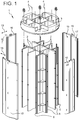
- the figure 1 is a storage device 1 for irradiated nuclear fuel assemblies in a package (not shown) for transporting and / or storing the fuel assemblies.
- the storage device 1 is called basket in the following description.
- the basket 1 comprises a head plate 3 and a bottom (not shown).
- the basket 1 comprises a plurality of adjacent cells 2, the latter each extending along a longitudinal axis 4 of the basket.
- the cells 2 are of square section. They are able to receive each a fuel assembly of square section. Nevertheless, the fuel assemblies and / or the cells 2 may also adopt other forms, such as a hexagonal shape.
- the cells 2 are provided so as to be juxtaposed to each other. They are made through a plurality of partitions 6, 8 and 10.
- the partitions 6, 8 and 10 are divided into three sets of separate partitions, defined respectively by a first set of internal partitions 6, a second set of internal partitions 8, and a set of peripheral partitions 10 located radially at the periphery of the internal partitions 6 and 8 relative to the longitudinal axis 4 of the basket.
- the partitions 6, 8, 10 are common to several cells 2. As such, it is noted that the internal partitions 6, 8 generally participate in the delimitation of several cells 2 located on either side of the internal partition 6, 8 concerned.
- the partitions 6, 8 comprise one or more walls 80, 82, 84 intended to separate the cells 2. These walls 80, 82, 84 take roughly the shape of a plate.
- the internal partitions 6, 8 are assembled together so as to be arranged parallel and perpendicular to each other, to form cells 2 of square section.
- the first internal partitions 6 are arranged parallel to each other, as well as the second internal partitions 8 between them.
- the first internal partitions 6 are assembled so as to be substantially perpendicular to the second internal partitions 8.
- the peripheral partitions 10 are fixed to the internal partitions 6, 8, so as to close the cells 2 at the periphery of the basket 1.
- the internal partitions 6, 8 constitute at least three of the four plane lateral faces delimiting a cell 2.
- the inner surfaces 17 of peripheral partitions 10 each optionally form one of the four plane lateral faces delimiting a cell 2.
- These inner surfaces 17 are oriented towards the inside of the basket 1, as opposed to the outer surfaces 19 of the peripheral partitions 10 which are situated at the periphery of the basket 1 and which delimit the outside of the basket 1.
- the surfaces outer 19 are preferably arcs of circles, so as to facilitate the insertion / removal of the basket 1 in the circular cavity of a package (not shown).
- the internal partitions 6 and 8 are made in one piece, so as to extend each along the entire length of / the cells 2 they define.
- the peripheral partitions 10 are made in one piece, so as to extend each along the entire length of the cells 2 they define.
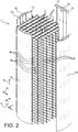
- the cells 2 are formed by means of a plurality of structural assemblies 6a, 8a with notches stacked in a stacking direction 11 parallel to the longitudinal axis 4 of the basket.
- the stacking direction 11 extends from a storage device bottom to a basket head plate.
- the height of the basket is also referred to as the stacking direction 11.
- the directions 11, 13 and 15 are orthogonal two by two.
- the structural assemblies with notches 6a, 8a are therefore crisscrossed perpendicularly.
- the structural assemblies 6a, 8a extend between at least two opposite peripheral partitions 10 to which they are attached.
- the peripheral partitions 10 are made in one piece.
- each peripheral wall 10 is made via a plurality of stacked structural assemblies.
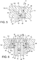
- the Figures 3 and 4 represent the tightening of one of the internal partitions 6, 8 in a housing of a peripheral wall 10 of a basket 1, according to the first or the second embodiment.
- the internal partition 6, 8 comprises two parallel walls 82, 84 separated by a spacing.
- the walls 82, 84 are preferably identical.
- Each of the walls 82, 84 has an outer lateral surface 81 and an internal lateral surface 85, of so that the outer lateral surface 81 and the inner lateral surface 85 are on either side of the wall 82, 84.
- the spacing e 1 is kept constant, for example by means of spacers (not shown) bearing on the inner lateral surfaces 85, within the spacing e 1 .
- the end of the internal partition 6, 8 is housed in a recess 101 which is formed in the peripheral wall 10 and which comprises two housings 100 for accommodating the walls 82, 84.
- each of the parallel walls 82, 84 of the internal partition 6, 8 is received in one of the housings 100 of the peripheral partition 10.
- These housings 100 each comprise two opposite and parallel side surfaces 102, 106.
- the lateral surfaces 102 The housings 100 open at an inner surface 17 of the peripheral wall 10, so that the housing side surfaces 102, 106 are orthogonal to the interior surface 17.
- Inner 17 and the internal partition 6, 8 delimit two contiguous cells 2, on either side of the internal partition 6, 8.
- the outer side surface 81 of each of the walls 82, 84 is pressed against one of the housing side surfaces 102, 106 by a clamping means 9.
- the outer side surfaces 81 have a shape complementary to the housing side surfaces 102, 106, to promote the thermal contact of the internal partitions 6, 8 with the peripheral partitions 10.
- the housing side surfaces 102, 106 of an inner wall end 6, 8 are two by two parallel.
- the clamping means 9 comprises a plurality of clamping members 90 spaced apart from one another along the height of the basket 1.
- Each clamping means 90 comprises a screw 92 and a nut 96 cooperating with the screw 92.
- the screws are accommodated in holes 91 of the peripheral wall 10, passing through the outer surface 19.
- the clamping elements 90 can be tightened / loosened from the outside of the basket 1, by acting on the screw heads 92.
- nut 96 is located between two jaws 94, so that the jaws 94 are solicited apart by the nut 96 and the screw 92 to press the side wall surfaces 81 against the lateral surfaces 102 of housing.
- the nut 96 has two first inclined surfaces 97 and the peripheral wall 10 comprises, at each jaw 94, two second inclined surfaces 95 of complementary shape to the first inclined surfaces 97.
- the first surfaces and second inclined surfaces 95, 97 are intended to be supported on one another, so as to maximize the mechanical contact surface between them and promote lateral clamping of the walls 82, 84 of internal partition 6, 8 in their housing 100.
- the clamping elements 90 can each exert a lateral clamping force Fi whose value is independent of that of the other clamping elements 90, as a function of the tension exerted on the screw 92 and the nut 96.
- the clamping elements 90 allow then to take all the possible differential expansions and the possible manufacturing and assembly tolerances of the internal partitions 6, 8 and / or the peripheral partitions 10 more easily.
- independent clamping elements 90 and spaced apart from each other along the height of the basket 1 allow in particular a mechanical and thermal contact of the internal partition 6, 8 and the peripheral wall 10 over substantially the entire height of the basket 1, that is to say for example at least% of the height of the peripheral wall 10.
- the jaws 94 are formed in one piece, in particular by extrusion, with the peripheral partition 10.
- the walls 82, 84 of the internal partition are therefore in thermal contact with the peripheral wall 10, at least at the level of the two lateral surfaces 102 , 106 opposite of housing.
- the walls 82, 84 are thus clamped in their housing 100.
- the first lateral surface 102 of the housing 100 then forms a first nip surface of each wall 82, 84 and the second lateral surface 106 of the housing 100 forms a second surface of pinching of this wall 82, 84.
- the internal partition 6, 8 and the clamping elements 90 are substantially symmetrical by plane plane symmetry parallel to the walls 82, 84 and passing through the axis 93.
- first inclined surfaces 97 are inclined towards the outer surface 19.
- the walls 82, 84 are in contact with each of the bottom 104 of their respective housing 100.
- the clamping elements 90 of the embodiment of FIG. Figures 3 and 4 are the only means of fixing the internal partition 6, 8 to the peripheral wall 10.
- each jaw 94 could be formed integrally with one of the walls 82, 84 of walls or attached to one of the walls 82, 84, so as to project from the remainder of the inner wall surface 85.
- These variants of embodiments may have the advantage of allowing easier machining of the jaws 94.
- the internal partition 6, 8 fixed to the peripheral wall 10 and / or the clamping elements 90 could also have no plane symmetry.
- first inclined surfaces 97 could of course be of opposite inclinations, that is to say approaching one another towards the inner surface 17.
- the basket 1 may comprise fastening means (not shown) of the internal partitions 6, 8 to the peripheral partitions 10, the clamping means 9 serving only to press the wall or walls 80, 82, 84 against at least one of the lateral surfaces 102, 106 of housing, once the internal wall 6, 8 is at least partially fixed to the peripheral wall 10.
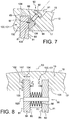
- the figure 5 represents an alternative embodiment of Figures 3 and 4 , wherein the internal partition 6, 8 comprises a single wall 80.
- This single wall 80 comprises two opposite outer side surfaces 81 and a ring 83 joining these two side surfaces.
- the recess 101 housing the end of the internal partition 6, 8 comprises a single housing 100 housing the end of the single wall 80.
- the edge 83 is spaced from the bottom 104 of the housing 100.
- the external lateral surfaces 81 of internal partition 6, 8 are pressed against the lateral surfaces 102, 106 of the housing by a clamping element 9 comprising a single jaw 94.
- the jaw 94 is for example formed in one piece by extrusion with the peripheral wall 10. This jaw 94 is clamped laterally against the wall 80 by a screw 92 cooperating with a nut 96 received in a housing 99 nut.
- the nut housing opens on the inner surface 17, so as to be locally orthogonal to the inner surface 17.
- the variant embodiment of the figure 6 differs from that of Figures 3 and 4 in that it comprises two clamping elements 90 in a transverse sectional plane of the basket 1. Furthermore, the clamping elements 90 are received at least partially in the housings 100, and the clamping elements 90 are free of jaws 94.
- the recess 101 receiving the end of the internal partition 6, 8 comprises two housings 100 separated from each other by an intermediate wall 108 of the peripheral partition 10. Each of the walls 82, 84 is clamped between a first pinch surface formed by a housing side wall 106 and a second nip surface 109 formed by the contact surface of the nut 96 with the wall 82, 84 it tightens.
- the clamping elements 90 each comprise a screw 92 and a nut cooperating with the screw 92.
- the screw holes 91 open into the housings 100 at the level of the housing funds 104.
- the nuts 96 are located in the housings 100, bearing against the outer wall surface 81 82, 84 along the second nipping surface 109.
- the nuts 96 bear the first inclined surfaces 97 and the second inclined surfaces 95 form the first side surfaces 102 of housing.
- the second inclined surfaces 95 are cut directly into the peripheral wall 10, so as to open at the inner surface 17 at an angle other than 90 ° with the interior surface 17.
- the screws 92 are tightened with a clamping force F 2 oriented in the longitudinal direction of the internal partition 6, 8, that is to say in the first direction 13 or the second direction 15.
- the nuts 96 then exert directly a lateral clamping force Fi on the outer side wall faces 81, 84, so as to press the inner side wall faces 85, 84 against the second side housing surfaces 106.
- the spacing e 1 between the walls 82, 84 of internal partitions is kept constant by a transverse spacer 86 resting on the inner lateral surfaces 85 of the wall 82, 84 and by the portion of the peripheral partition 10 situated between the two contiguous housings 100 .
- the variant embodiment of the figure 7 differs from the embodiment of the figure 5 in that the clamping element 90 is at least partially in the housing 100, and in that the clamping element 90 does not comprise a nut or jaw.
- the recess 101 includes a single housing 100 which partially houses the pusher 96, the wall 80 being clamped between a first nip surface formed by the first housing side surface 102 and a second nip surface 109 which is the contact surface of the housing. pusher 96 with the wall 80.
- the wall 80 comprises two external lateral surfaces 81 opposite and joined by a song 83.
- the clamping element 90 comprises a screw 92 whose head is accessible from the outside of the basket 1, and a push-piece 96 for pressing one of the surfaces external side 81 against the first side surface 102 of housing. Due to the pusher 96, the other external lateral wall surface 81 is not in mechanical and thermal contact with the second lateral housing surface 106.
- the screw 92 bears on the pusher 96 which is located at least partially in a recess 99 of the peripheral wall 10, opening into the housing 100.
- the edge 83 of wall is located at a distance from the bottom 104 of the housing.
- the figure 8 represents another variant of the invention which differs from the embodiment of the Figures 3 and 4 in that the clamping elements 90 do not have screws, no nuts and no jaws. Furthermore, the clamping elements 90 are located at a distance from the peripheral partition 10. Finally, the two walls 82, 84 of the internal partition 6, 8 are received in a single housing 100. This single housing 100 forms the recess 101, the two outer side surfaces 81 of the walls 82, 84 being respectively pressed against the first housing side surface 102 and the second housing side surface 106.
- the internal wall end 6, 8 and the clamping element 90 are symmetrical by plane symmetry passing through the axis 93.
- the clamping element 90 shown in this figure comprises an elastic clamping element 98 and a constraint element 920 of the elastic clamping member 98, the constraint element 920 also for holding the clamping member 98 between the inner side surfaces 85.
- the elastic clamping element 98 takes for example the form of a set of spring steel curved spring washers.
- the set of washers is located in the spacing e 1 and is supported on the inner side surfaces 81 which it solicits in spacing from one another.
- the outer wall surfaces 81, 84 are then pressed against the lateral surfaces 102, 106 of housing, with a lateral force Fi.
- the constraint element 920 is intended to compress the elastic clamping element 98, so as to allow it to be inserted between the internal lateral wall surfaces 81. Furthermore, the constraint element 920 can also serve to bias the resilient clamping member 98 apart, so that the elastic clamping member 98 sufficiently distances the inner side surfaces 85 from each other for pressing the outer side surfaces 81 against the housing side surfaces 102, 106.
- Basket 1 is assembled according to the method described below.
- the internal partitions 6, 8 are previously fixed to each other so as to form the central cells 2 of the basket.
- the peripheral partitions 10 are assembled to the internal partitions 6, 8, so as to close the peripheral cells 2 laterally.
- the ends of the internal partitions 6, 8 are each housed in their respective recess 101, by plating at least one of the wall side surfaces 81, 85 of the internal partition against at least one of the housing surfaces 102 , 106 of the recess.
- a bottom and a head plate 3 contribute to maintaining all the partitions of the basket 1, on either side of the height 11 of the basket, the head plate also allowing the handling of the basket.
- the two opposite ends of the walls 80, 82, 84 of internal partitions 6, 8 are first received in their respective housings 100.
- the clamping means 9 located at one of the plate ends then at least one of the side surfaces 81, 85 of wall 80, 82, 84 against at least one of the side surfaces 102, 106 housing.
- the wall 80, 82, 84 is then located between this lateral surface 102, 106 of housing and the clamping means 9.
- the internal partition 6, 8 comprises two walls 82, 84
- these two walls 82, 84 are preferably first received both in their housing 100, before the clamping means 9 plates against at least one of the surfaces lateral 102, 106 housing.
- the internal partitions 6, 8 may be at least partially fixed to the peripheral partitions 10, before the clamping means 9 ensures the plating of at least one of the lateral surfaces 81, 85 of the at least one wall 80, 82, 84 against the corresponding housing side surface 102, 106.
- the walls 80, 82, 84 may optionally slide along the direction of elongation of the internal partitions 6, 8, that is to say along the first direction 13 or along the second direction 15, after their clamping against at least one of the lateral housing surfaces 102, 106 by the clamping means 9. This sliding makes it possible for example to better compensate for possible differential expansions of the basket 1 and / or to take up shocks to the basket 1 .
Landscapes
- Physics & Mathematics (AREA)
- Engineering & Computer Science (AREA)
- General Engineering & Computer Science (AREA)
- High Energy & Nuclear Physics (AREA)
- Plasma & Fusion (AREA)
- Details Of Rigid Or Semi-Rigid Containers (AREA)
- Packages (AREA)
- Buffer Packaging (AREA)
Applications Claiming Priority (2)
| Application Number | Priority Date | Filing Date | Title |
|---|---|---|---|
| FR1457789A FR3024919B1 (fr) | 2014-08-13 | 2014-08-13 | Panier pour le transport et/ou l'entreposage de matieres radioactives |
| PCT/EP2015/068331 WO2016023849A1 (fr) | 2014-08-13 | 2015-08-10 | Panier pour le transport et/ou l'entreposage de matieres radioactives |
Publications (2)
| Publication Number | Publication Date |
|---|---|
| EP3180790A1 EP3180790A1 (fr) | 2017-06-21 |
| EP3180790B1 true EP3180790B1 (fr) | 2018-07-11 |
Family
ID=51862462
Family Applications (1)
| Application Number | Title | Priority Date | Filing Date |
|---|---|---|---|
| EP15753656.6A Active EP3180790B1 (fr) | 2014-08-13 | 2015-08-10 | Panier pour le transport et/ou l'entreposage de matieres radioactives |
Country Status (8)
| Country | Link |
|---|---|
| US (1) | US10573422B2 (zh) |
| EP (1) | EP3180790B1 (zh) |
| JP (1) | JP6674444B2 (zh) |
| KR (1) | KR102464336B1 (zh) |
| CN (1) | CN106663484B (zh) |
| ES (1) | ES2690475T3 (zh) |
| FR (1) | FR3024919B1 (zh) |
| WO (1) | WO2016023849A1 (zh) |
Families Citing this family (6)
| Publication number | Priority date | Publication date | Assignee | Title |
|---|---|---|---|---|
| FR3044819B1 (fr) | 2015-12-03 | 2017-12-22 | Tn Int | Dispositif de rangement pour l'entreposage et/ou le transport d'assemblages de combustible nucleaire, comprenant des etages a fonctions differenciees |
| TWI795484B (zh) * | 2017-12-20 | 2023-03-11 | 美商Tn美國有限責任公司 | 用於燃料總成的模組提籃總成 |
| FR3077411B1 (fr) | 2018-01-26 | 2020-03-06 | Tn International | Panier de rangement pour matieres radioactives, presentant un encombrement optimise ainsi que des logements de geometrie plus precise |
| KR101974773B1 (ko) * | 2018-01-26 | 2019-09-05 | 두산중공업 주식회사 | 원자로 용기의 차폐 및 절단 장치 |
| EP4073823A4 (en) | 2019-12-09 | 2024-03-20 | Holtec International | INTEGRATED NUCLEAR FUEL STORAGE SYSTEM |
| SE2251135A1 (en) * | 2022-09-30 | 2024-03-31 | Svensk Kaernbraenslehantering Ab | Devices and methods |
Family Cites Families (8)
| Publication number | Priority date | Publication date | Assignee | Title |
|---|---|---|---|---|
| US5651038A (en) * | 1996-02-06 | 1997-07-22 | Sierra Nuclear Corporation | Sealed basket for pressurized water reactor fuel assemblies |
| FR2747825B1 (fr) | 1996-04-19 | 1998-05-22 | Transnucleaire | Casier de rangement d'assemblages combustibles nucleaires dont les alveoles contiennent un profile neutrophage |
| JP4052451B2 (ja) * | 2002-11-08 | 2008-02-27 | 三菱重工業株式会社 | リサイクル燃料集合体格納用バスケット及びリサイクル燃料集合体格納容器 |
| FR2865571B1 (fr) * | 2004-01-23 | 2006-04-28 | Cogema Logistics | Dispositif de rangement prevu pour etre place dans un emballage destine au transport de matieres radioactives |
| JP4621699B2 (ja) * | 2007-02-13 | 2011-01-26 | 株式会社東芝 | 使用済燃料貯蔵ラック |
| JP5010491B2 (ja) * | 2008-01-30 | 2012-08-29 | 三菱重工業株式会社 | リサイクル燃料集合体収納用バスケット及びリサイクル燃料集合体収納容器、並びにリサイクル燃料集合体収納用バスケットの製造方法 |
| FR2961942B1 (fr) * | 2010-06-25 | 2014-04-11 | Tn Int | Conteneur pour le transport et/ou l'entreposage de matieres radioactives |
| JP5205540B1 (ja) * | 2012-09-20 | 2013-06-05 | 株式会社カワハラ技研 | 放射性汚染物質収納容器 |
-
2014
- 2014-08-13 FR FR1457789A patent/FR3024919B1/fr not_active Expired - Fee Related
-
2015
- 2015-08-10 JP JP2017506303A patent/JP6674444B2/ja active Active
- 2015-08-10 EP EP15753656.6A patent/EP3180790B1/fr active Active
- 2015-08-10 CN CN201580043123.6A patent/CN106663484B/zh active Active
- 2015-08-10 US US15/502,916 patent/US10573422B2/en active Active
- 2015-08-10 WO PCT/EP2015/068331 patent/WO2016023849A1/fr active Application Filing
- 2015-08-10 KR KR1020177003336A patent/KR102464336B1/ko active IP Right Grant
- 2015-08-10 ES ES15753656.6T patent/ES2690475T3/es active Active
Non-Patent Citations (1)
| Title |
|---|
| None * |
Also Published As
| Publication number | Publication date |
|---|---|
| WO2016023849A1 (fr) | 2016-02-18 |
| KR20170043517A (ko) | 2017-04-21 |
| JP6674444B2 (ja) | 2020-04-01 |
| FR3024919A1 (fr) | 2016-02-19 |
| EP3180790A1 (fr) | 2017-06-21 |
| ES2690475T3 (es) | 2018-11-21 |
| CN106663484B (zh) | 2018-09-07 |
| US10573422B2 (en) | 2020-02-25 |
| FR3024919B1 (fr) | 2016-09-30 |
| KR102464336B1 (ko) | 2022-11-07 |
| US20170229199A1 (en) | 2017-08-10 |
| JP2017523428A (ja) | 2017-08-17 |
| CN106663484A (zh) | 2017-05-10 |
Similar Documents
| Publication | Publication Date | Title |
|---|---|---|
| EP3180790B1 (fr) | Panier pour le transport et/ou l'entreposage de matieres radioactives | |
| EP1212755B1 (fr) | Panier de rangement pour matieres radioactives | |
| FR2933525A1 (fr) | Ratelier de stockage d'assemblages de combustible nucleaire, frais ou irradies | |
| EP2208205B1 (fr) | Grille de maintien de crayons de combustible nucleaire, et ossature et assemblage comprenant une telle grille | |
| FR3012586A1 (fr) | Systeme de maintien d'au moins un panneau solaire sur un module solaire et module solaire le comportant | |
| EP2751821B1 (fr) | Couvercle de connexion d'ensembles de stockage d'energie | |
| EP2810286A1 (fr) | Entretoise de positionnement, module de stockage d'energie l'utilisant et procede d'assemblage du module | |
| FR3044819A1 (fr) | Dispositif de rangement pour l'entreposage et/ou le transport d'assemblages de combustible nucleaire, comprenant des etages a fonctions differenciees | |
| FR2505262A1 (fr) | Dispositif permettant de maintenir en liasse des feuilles empilees et perforees | |
| EP0522981A1 (fr) | Batterie d'accumulateurs monobloc | |
| FR2969744A1 (fr) | Element et methode de fixation d'au moins un panneau photovoltaique sur un rail et installation comprenant au moins un tel element | |
| EP3363022A1 (fr) | Element de refroidissement avec embase pour evacuer de la chaleur d'un emballage | |
| WO2023026013A1 (fr) | Dispositif de rangement pour l'entreposage et/ou le transport d'assemblages de combustible nucleaire, présentant une conception à résistance mécanique améliorée | |
| EP3743928B1 (fr) | Panier de rangement pour matieres radioactives, presentant un encombrement optimise ainsi que des logements de geometrie plus precise | |
| EP3816458B1 (fr) | Agrafe de maintien de deux elements plans | |
| WO2021234106A1 (fr) | Ensemble électrochimique, batterie et procédé correspondants | |
| WO2004105048A2 (fr) | Dispositif de rangement pour le transport/stockage d'assemblages de combustible nucleaire | |
| EP4136660A1 (fr) | Dispositif de rangement pour l'entreposage et/ou le transport d'assemblages de combustible nucleaire, presentant une conception a couts reduits | |
| EP4073822A1 (fr) | Dispositif de rangement pour l'entreposage et/ou le transport d'assemblages de combustible nucleaire, présentant une conception à coûts réduits | |
| FR3079505A1 (fr) | Piece pour la separation de tubes superposes | |
| FR3102518A3 (fr) | Agrafe de maintien de deux elements plans | |
| BE894241A (fr) | Module de systeme de construction | |
| FR3053160A1 (fr) | Dispositif d'assemblage d'accumulateurs electriques | |
| FR2748542A1 (fr) | Dispositif pour l'accouplement etanche de deux tubes lisses | |
| WO2009081076A2 (fr) | Dispositif d'assemblage reversible |
Legal Events
| Date | Code | Title | Description |
|---|---|---|---|
| STAA | Information on the status of an ep patent application or granted ep patent |
Free format text: STATUS: THE INTERNATIONAL PUBLICATION HAS BEEN MADE |
|
| PUAI | Public reference made under article 153(3) epc to a published international application that has entered the european phase |
Free format text: ORIGINAL CODE: 0009012 |
|
| STAA | Information on the status of an ep patent application or granted ep patent |
Free format text: STATUS: REQUEST FOR EXAMINATION WAS MADE |
|
| 17P | Request for examination filed |
Effective date: 20170214 |
|
| AK | Designated contracting states |
Kind code of ref document: A1 Designated state(s): AL AT BE BG CH CY CZ DE DK EE ES FI FR GB GR HR HU IE IS IT LI LT LU LV MC MK MT NL NO PL PT RO RS SE SI SK SM TR |
|
| AX | Request for extension of the european patent |
Extension state: BA ME |
|
| DAV | Request for validation of the european patent (deleted) | ||
| DAX | Request for extension of the european patent (deleted) | ||
| GRAP | Despatch of communication of intention to grant a patent |
Free format text: ORIGINAL CODE: EPIDOSNIGR1 |
|
| STAA | Information on the status of an ep patent application or granted ep patent |
Free format text: STATUS: GRANT OF PATENT IS INTENDED |
|
| INTG | Intention to grant announced |
Effective date: 20180201 |
|
| RIN1 | Information on inventor provided before grant (corrected) |
Inventor name: DELAGE, OLIVIER Inventor name: ROGER, CHRISTOPHE |
|
| GRAS | Grant fee paid |
Free format text: ORIGINAL CODE: EPIDOSNIGR3 |
|
| GRAA | (expected) grant |
Free format text: ORIGINAL CODE: 0009210 |
|
| STAA | Information on the status of an ep patent application or granted ep patent |
Free format text: STATUS: THE PATENT HAS BEEN GRANTED |
|
| AK | Designated contracting states |
Kind code of ref document: B1 Designated state(s): AL AT BE BG CH CY CZ DE DK EE ES FI FR GB GR HR HU IE IS IT LI LT LU LV MC MK MT NL NO PL PT RO RS SE SI SK SM TR |
|
| REG | Reference to a national code |
Ref country code: GB Ref legal event code: FG4D Free format text: NOT ENGLISH |
|
| REG | Reference to a national code |
Ref country code: CH Ref legal event code: EP |
|
| REG | Reference to a national code |
Ref country code: AT Ref legal event code: REF Ref document number: 1017759 Country of ref document: AT Kind code of ref document: T Effective date: 20180715 |
|
| REG | Reference to a national code |
Ref country code: IE Ref legal event code: FG4D Free format text: LANGUAGE OF EP DOCUMENT: FRENCH |
|
| REG | Reference to a national code |
Ref country code: DE Ref legal event code: R096 Ref document number: 602015013490 Country of ref document: DE |
|
| REG | Reference to a national code |
Ref country code: FR Ref legal event code: PLFP Year of fee payment: 4 |
|
| REG | Reference to a national code |
Ref country code: CH Ref legal event code: NV Representative=s name: BOVARD AG PATENT- UND MARKENANWAELTE, CH |
|
| REG | Reference to a national code |
Ref country code: SE Ref legal event code: TRGR |
|
| REG | Reference to a national code |
Ref country code: NL Ref legal event code: MP Effective date: 20180711 |
|
| REG | Reference to a national code |
Ref country code: ES Ref legal event code: FG2A Ref document number: 2690475 Country of ref document: ES Kind code of ref document: T3 Effective date: 20181121 |
|
| REG | Reference to a national code |
Ref country code: LT Ref legal event code: MG4D |
|
| REG | Reference to a national code |
Ref country code: AT Ref legal event code: MK05 Ref document number: 1017759 Country of ref document: AT Kind code of ref document: T Effective date: 20180711 |
|
| PG25 | Lapsed in a contracting state [announced via postgrant information from national office to epo] |
Ref country code: NL Free format text: LAPSE BECAUSE OF FAILURE TO SUBMIT A TRANSLATION OF THE DESCRIPTION OR TO PAY THE FEE WITHIN THE PRESCRIBED TIME-LIMIT Effective date: 20180711 |
|
| PG25 | Lapsed in a contracting state [announced via postgrant information from national office to epo] |
Ref country code: FI Free format text: LAPSE BECAUSE OF FAILURE TO SUBMIT A TRANSLATION OF THE DESCRIPTION OR TO PAY THE FEE WITHIN THE PRESCRIBED TIME-LIMIT Effective date: 20180711 Ref country code: PL Free format text: LAPSE BECAUSE OF FAILURE TO SUBMIT A TRANSLATION OF THE DESCRIPTION OR TO PAY THE FEE WITHIN THE PRESCRIBED TIME-LIMIT Effective date: 20180711 Ref country code: BG Free format text: LAPSE BECAUSE OF FAILURE TO SUBMIT A TRANSLATION OF THE DESCRIPTION OR TO PAY THE FEE WITHIN THE PRESCRIBED TIME-LIMIT Effective date: 20181011 Ref country code: AT Free format text: LAPSE BECAUSE OF FAILURE TO SUBMIT A TRANSLATION OF THE DESCRIPTION OR TO PAY THE FEE WITHIN THE PRESCRIBED TIME-LIMIT Effective date: 20180711 Ref country code: NO Free format text: LAPSE BECAUSE OF FAILURE TO SUBMIT A TRANSLATION OF THE DESCRIPTION OR TO PAY THE FEE WITHIN THE PRESCRIBED TIME-LIMIT Effective date: 20181011 Ref country code: GR Free format text: LAPSE BECAUSE OF FAILURE TO SUBMIT A TRANSLATION OF THE DESCRIPTION OR TO PAY THE FEE WITHIN THE PRESCRIBED TIME-LIMIT Effective date: 20181012 Ref country code: LT Free format text: LAPSE BECAUSE OF FAILURE TO SUBMIT A TRANSLATION OF THE DESCRIPTION OR TO PAY THE FEE WITHIN THE PRESCRIBED TIME-LIMIT Effective date: 20180711 Ref country code: RS Free format text: LAPSE BECAUSE OF FAILURE TO SUBMIT A TRANSLATION OF THE DESCRIPTION OR TO PAY THE FEE WITHIN THE PRESCRIBED TIME-LIMIT Effective date: 20180711 Ref country code: IS Free format text: LAPSE BECAUSE OF FAILURE TO SUBMIT A TRANSLATION OF THE DESCRIPTION OR TO PAY THE FEE WITHIN THE PRESCRIBED TIME-LIMIT Effective date: 20181111 |
|
| PG25 | Lapsed in a contracting state [announced via postgrant information from national office to epo] |
Ref country code: HR Free format text: LAPSE BECAUSE OF FAILURE TO SUBMIT A TRANSLATION OF THE DESCRIPTION OR TO PAY THE FEE WITHIN THE PRESCRIBED TIME-LIMIT Effective date: 20180711 Ref country code: AL Free format text: LAPSE BECAUSE OF FAILURE TO SUBMIT A TRANSLATION OF THE DESCRIPTION OR TO PAY THE FEE WITHIN THE PRESCRIBED TIME-LIMIT Effective date: 20180711 Ref country code: LV Free format text: LAPSE BECAUSE OF FAILURE TO SUBMIT A TRANSLATION OF THE DESCRIPTION OR TO PAY THE FEE WITHIN THE PRESCRIBED TIME-LIMIT Effective date: 20180711 |
|
| REG | Reference to a national code |
Ref country code: DE Ref legal event code: R097 Ref document number: 602015013490 Country of ref document: DE |
|
| PG25 | Lapsed in a contracting state [announced via postgrant information from national office to epo] |
Ref country code: MC Free format text: LAPSE BECAUSE OF FAILURE TO SUBMIT A TRANSLATION OF THE DESCRIPTION OR TO PAY THE FEE WITHIN THE PRESCRIBED TIME-LIMIT Effective date: 20180711 Ref country code: CZ Free format text: LAPSE BECAUSE OF FAILURE TO SUBMIT A TRANSLATION OF THE DESCRIPTION OR TO PAY THE FEE WITHIN THE PRESCRIBED TIME-LIMIT Effective date: 20180711 Ref country code: EE Free format text: LAPSE BECAUSE OF FAILURE TO SUBMIT A TRANSLATION OF THE DESCRIPTION OR TO PAY THE FEE WITHIN THE PRESCRIBED TIME-LIMIT Effective date: 20180711 Ref country code: RO Free format text: LAPSE BECAUSE OF FAILURE TO SUBMIT A TRANSLATION OF THE DESCRIPTION OR TO PAY THE FEE WITHIN THE PRESCRIBED TIME-LIMIT Effective date: 20180711 Ref country code: IT Free format text: LAPSE BECAUSE OF FAILURE TO SUBMIT A TRANSLATION OF THE DESCRIPTION OR TO PAY THE FEE WITHIN THE PRESCRIBED TIME-LIMIT Effective date: 20180711 Ref country code: LU Free format text: LAPSE BECAUSE OF NON-PAYMENT OF DUE FEES Effective date: 20180810 |
|
| PLBE | No opposition filed within time limit |
Free format text: ORIGINAL CODE: 0009261 |
|
| STAA | Information on the status of an ep patent application or granted ep patent |
Free format text: STATUS: NO OPPOSITION FILED WITHIN TIME LIMIT |
|
| REG | Reference to a national code |
Ref country code: IE Ref legal event code: MM4A |
|
| PG25 | Lapsed in a contracting state [announced via postgrant information from national office to epo] |
Ref country code: DK Free format text: LAPSE BECAUSE OF FAILURE TO SUBMIT A TRANSLATION OF THE DESCRIPTION OR TO PAY THE FEE WITHIN THE PRESCRIBED TIME-LIMIT Effective date: 20180711 Ref country code: SK Free format text: LAPSE BECAUSE OF FAILURE TO SUBMIT A TRANSLATION OF THE DESCRIPTION OR TO PAY THE FEE WITHIN THE PRESCRIBED TIME-LIMIT Effective date: 20180711 Ref country code: SM Free format text: LAPSE BECAUSE OF FAILURE TO SUBMIT A TRANSLATION OF THE DESCRIPTION OR TO PAY THE FEE WITHIN THE PRESCRIBED TIME-LIMIT Effective date: 20180711 |
|
| 26N | No opposition filed |
Effective date: 20190412 |
|
| PG25 | Lapsed in a contracting state [announced via postgrant information from national office to epo] |
Ref country code: IE Free format text: LAPSE BECAUSE OF NON-PAYMENT OF DUE FEES Effective date: 20180810 |
|
| PG25 | Lapsed in a contracting state [announced via postgrant information from national office to epo] |
Ref country code: SI Free format text: LAPSE BECAUSE OF FAILURE TO SUBMIT A TRANSLATION OF THE DESCRIPTION OR TO PAY THE FEE WITHIN THE PRESCRIBED TIME-LIMIT Effective date: 20180711 |
|
| PG25 | Lapsed in a contracting state [announced via postgrant information from national office to epo] |
Ref country code: MT Free format text: LAPSE BECAUSE OF FAILURE TO SUBMIT A TRANSLATION OF THE DESCRIPTION OR TO PAY THE FEE WITHIN THE PRESCRIBED TIME-LIMIT Effective date: 20180711 |
|
| PG25 | Lapsed in a contracting state [announced via postgrant information from national office to epo] |
Ref country code: TR Free format text: LAPSE BECAUSE OF FAILURE TO SUBMIT A TRANSLATION OF THE DESCRIPTION OR TO PAY THE FEE WITHIN THE PRESCRIBED TIME-LIMIT Effective date: 20180711 |
|
| PG25 | Lapsed in a contracting state [announced via postgrant information from national office to epo] |
Ref country code: PT Free format text: LAPSE BECAUSE OF FAILURE TO SUBMIT A TRANSLATION OF THE DESCRIPTION OR TO PAY THE FEE WITHIN THE PRESCRIBED TIME-LIMIT Effective date: 20180711 |
|
| PG25 | Lapsed in a contracting state [announced via postgrant information from national office to epo] |
Ref country code: MK Free format text: LAPSE BECAUSE OF NON-PAYMENT OF DUE FEES Effective date: 20180711 Ref country code: HU Free format text: LAPSE BECAUSE OF FAILURE TO SUBMIT A TRANSLATION OF THE DESCRIPTION OR TO PAY THE FEE WITHIN THE PRESCRIBED TIME-LIMIT; INVALID AB INITIO Effective date: 20150810 Ref country code: CY Free format text: LAPSE BECAUSE OF FAILURE TO SUBMIT A TRANSLATION OF THE DESCRIPTION OR TO PAY THE FEE WITHIN THE PRESCRIBED TIME-LIMIT Effective date: 20180711 |
|
| P01 | Opt-out of the competence of the unified patent court (upc) registered |
Effective date: 20230526 |
|
| PGFP | Annual fee paid to national office [announced via postgrant information from national office to epo] |
Ref country code: GB Payment date: 20230825 Year of fee payment: 9 Ref country code: ES Payment date: 20230905 Year of fee payment: 9 Ref country code: CH Payment date: 20230919 Year of fee payment: 9 |
|
| PGFP | Annual fee paid to national office [announced via postgrant information from national office to epo] |
Ref country code: SE Payment date: 20230825 Year of fee payment: 9 Ref country code: FR Payment date: 20230828 Year of fee payment: 9 Ref country code: DE Payment date: 20230824 Year of fee payment: 9 Ref country code: BE Payment date: 20230823 Year of fee payment: 9 |