EP3179968B1 - Dispositifs d'implant d'accès aux sinus paranasaux et produits et procédés associés - Google Patents
Dispositifs d'implant d'accès aux sinus paranasaux et produits et procédés associés Download PDFInfo
- Publication number
- EP3179968B1 EP3179968B1 EP15748382.7A EP15748382A EP3179968B1 EP 3179968 B1 EP3179968 B1 EP 3179968B1 EP 15748382 A EP15748382 A EP 15748382A EP 3179968 B1 EP3179968 B1 EP 3179968B1
- Authority
- EP
- European Patent Office
- Prior art keywords
- implant device
- conduit
- head
- millimeters
- paranasal sinus
- Prior art date
- Legal status (The legal status is an assumption and is not a legal conclusion. Google has not performed a legal analysis and makes no representation as to the accuracy of the status listed.)
- Active
Links
- 239000007943 implant Substances 0.000 title claims description 371
- 210000003695 paranasal sinus Anatomy 0.000 title claims description 113
- 238000000034 method Methods 0.000 title claims description 51
- 239000000463 material Substances 0.000 claims description 217
- 210000003128 head Anatomy 0.000 claims description 123
- 206010016717 Fistula Diseases 0.000 claims description 52
- 230000003890 fistula Effects 0.000 claims description 52
- 210000004561 lacrimal apparatus Anatomy 0.000 claims description 48
- 210000001519 tissue Anatomy 0.000 claims description 40
- 239000012530 fluid Substances 0.000 claims description 35
- 239000000080 wetting agent Substances 0.000 claims description 35
- 239000004599 antimicrobial Substances 0.000 claims description 32
- 238000002513 implantation Methods 0.000 claims description 32
- 229920001296 polysiloxane Polymers 0.000 claims description 29
- 238000004873 anchoring Methods 0.000 claims description 21
- 239000007788 liquid Substances 0.000 claims description 21
- 238000003860 storage Methods 0.000 claims description 19
- 238000004806 packaging method and process Methods 0.000 claims description 13
- 239000002202 Polyethylene glycol Substances 0.000 claims description 11
- 229920001223 polyethylene glycol Polymers 0.000 claims description 11
- 239000000017 hydrogel Substances 0.000 claims description 10
- -1 poly(ethylene oxide) Polymers 0.000 claims description 10
- 108700042778 Antimicrobial Peptides Proteins 0.000 claims description 9
- 102000044503 Antimicrobial Peptides Human genes 0.000 claims description 9
- 238000004891 communication Methods 0.000 claims description 9
- 229920000036 polyvinylpyrrolidone Polymers 0.000 claims description 7
- 239000001267 polyvinylpyrrolidone Substances 0.000 claims description 7
- 235000013855 polyvinylpyrrolidone Nutrition 0.000 claims description 7
- KIUKXJAPPMFGSW-DNGZLQJQSA-N (2S,3S,4S,5R,6R)-6-[(2S,3R,4R,5S,6R)-3-Acetamido-2-[(2S,3S,4R,5R,6R)-6-[(2R,3R,4R,5S,6R)-3-acetamido-2,5-dihydroxy-6-(hydroxymethyl)oxan-4-yl]oxy-2-carboxy-4,5-dihydroxyoxan-3-yl]oxy-5-hydroxy-6-(hydroxymethyl)oxan-4-yl]oxy-3,4,5-trihydroxyoxane-2-carboxylic acid Chemical compound CC(=O)N[C@H]1[C@H](O)O[C@H](CO)[C@@H](O)[C@@H]1O[C@H]1[C@H](O)[C@@H](O)[C@H](O[C@H]2[C@@H]([C@@H](O[C@H]3[C@@H]([C@@H](O)[C@H](O)[C@H](O3)C(O)=O)O)[C@H](O)[C@@H](CO)O2)NC(C)=O)[C@@H](C(O)=O)O1 KIUKXJAPPMFGSW-DNGZLQJQSA-N 0.000 claims description 6
- 229920003171 Poly (ethylene oxide) Polymers 0.000 claims description 6
- 229920002674 hyaluronan Polymers 0.000 claims description 6
- 229960003160 hyaluronic acid Drugs 0.000 claims description 6
- 239000003910 polypeptide antibiotic agent Substances 0.000 claims description 6
- 238000004519 manufacturing process Methods 0.000 claims description 5
- 230000003287 optical effect Effects 0.000 claims description 3
- 238000000847 optical profilometry Methods 0.000 claims description 3
- 229910052709 silver Inorganic materials 0.000 claims description 3
- 239000004332 silver Substances 0.000 claims description 3
- 210000001180 ethmoid sinus Anatomy 0.000 description 21
- 239000000047 product Substances 0.000 description 21
- 239000000203 mixture Substances 0.000 description 19
- 238000011282 treatment Methods 0.000 description 19
- 239000000654 additive Substances 0.000 description 18
- 230000000996 additive effect Effects 0.000 description 15
- 239000003795 chemical substances by application Substances 0.000 description 13
- 210000004086 maxillary sinus Anatomy 0.000 description 12
- 239000011248 coating agent Substances 0.000 description 11
- 238000000576 coating method Methods 0.000 description 11
- 229920000642 polymer Polymers 0.000 description 11
- 238000000465 moulding Methods 0.000 description 9
- 230000015572 biosynthetic process Effects 0.000 description 8
- 238000010276 construction Methods 0.000 description 8
- 210000001214 frontal sinus Anatomy 0.000 description 8
- 210000004083 nasolacrimal duct Anatomy 0.000 description 8
- 239000011342 resin composition Substances 0.000 description 8
- 239000000243 solution Substances 0.000 description 8
- 210000005252 bulbus oculi Anatomy 0.000 description 7
- 239000007822 coupling agent Substances 0.000 description 7
- 238000013461 design Methods 0.000 description 7
- 239000002243 precursor Substances 0.000 description 7
- 238000012986 modification Methods 0.000 description 6
- 230000004048 modification Effects 0.000 description 6
- 229920000052 poly(p-xylylene) Polymers 0.000 description 6
- 238000000926 separation method Methods 0.000 description 6
- 210000004872 soft tissue Anatomy 0.000 description 6
- 210000000795 conjunctiva Anatomy 0.000 description 5
- 238000001035 drying Methods 0.000 description 5
- 238000005470 impregnation Methods 0.000 description 5
- 229910052751 metal Inorganic materials 0.000 description 5
- 239000002184 metal Substances 0.000 description 5
- 230000035807 sensation Effects 0.000 description 5
- 210000003718 sphenoid sinus Anatomy 0.000 description 5
- BQCADISMDOOEFD-UHFFFAOYSA-N Silver Chemical compound [Ag] BQCADISMDOOEFD-UHFFFAOYSA-N 0.000 description 4
- TZCXTZWJZNENPQ-UHFFFAOYSA-L barium sulfate Chemical compound [Ba+2].[O-]S([O-])(=O)=O TZCXTZWJZNENPQ-UHFFFAOYSA-L 0.000 description 4
- 210000000988 bone and bone Anatomy 0.000 description 4
- 229920001577 copolymer Polymers 0.000 description 4
- 239000000945 filler Substances 0.000 description 4
- 230000036571 hydration Effects 0.000 description 4
- 238000006703 hydration reaction Methods 0.000 description 4
- 210000003928 nasal cavity Anatomy 0.000 description 4
- 229920001692 polycarbonate urethane Polymers 0.000 description 4
- 230000000845 anti-microbial effect Effects 0.000 description 3
- 230000032770 biofilm formation Effects 0.000 description 3
- 238000005229 chemical vapour deposition Methods 0.000 description 3
- 238000000151 deposition Methods 0.000 description 3
- 239000003814 drug Substances 0.000 description 3
- 229940079593 drug Drugs 0.000 description 3
- 210000001031 ethmoid bone Anatomy 0.000 description 3
- 210000000744 eyelid Anatomy 0.000 description 3
- 238000010438 heat treatment Methods 0.000 description 3
- 238000003780 insertion Methods 0.000 description 3
- 230000037431 insertion Effects 0.000 description 3
- 230000003993 interaction Effects 0.000 description 3
- 210000000826 nictitating membrane Anatomy 0.000 description 3
- 229920002635 polyurethane Polymers 0.000 description 3
- 239000004814 polyurethane Substances 0.000 description 3
- 238000012545 processing Methods 0.000 description 3
- 229920006268 silicone film Polymers 0.000 description 3
- 201000009890 sinusitis Diseases 0.000 description 3
- 239000007921 spray Substances 0.000 description 3
- 238000005507 spraying Methods 0.000 description 3
- 238000001356 surgical procedure Methods 0.000 description 3
- VRBFTYUMFJWSJY-UHFFFAOYSA-N 28804-46-8 Chemical compound ClC1CC(C=C2)=CC=C2C(Cl)CC2=CC=C1C=C2 VRBFTYUMFJWSJY-UHFFFAOYSA-N 0.000 description 2
- LYCAIKOWRPUZTN-UHFFFAOYSA-N Ethylene glycol Chemical compound OCCO LYCAIKOWRPUZTN-UHFFFAOYSA-N 0.000 description 2
- WHNWPMSKXPGLAX-UHFFFAOYSA-N N-Vinyl-2-pyrrolidone Chemical compound C=CN1CCCC1=O WHNWPMSKXPGLAX-UHFFFAOYSA-N 0.000 description 2
- 239000004372 Polyvinyl alcohol Substances 0.000 description 2
- KXJLGCBCRCSXQF-UHFFFAOYSA-N [diacetyloxy(ethyl)silyl] acetate Chemical compound CC(=O)O[Si](CC)(OC(C)=O)OC(C)=O KXJLGCBCRCSXQF-UHFFFAOYSA-N 0.000 description 2
- 238000004630 atomic force microscopy Methods 0.000 description 2
- 230000008901 benefit Effects 0.000 description 2
- 238000000748 compression moulding Methods 0.000 description 2
- 230000008021 deposition Effects 0.000 description 2
- 235000013870 dimethyl polysiloxane Nutrition 0.000 description 2
- 239000004205 dimethyl polysiloxane Substances 0.000 description 2
- 238000003618 dip coating Methods 0.000 description 2
- 210000003717 douglas' pouch Anatomy 0.000 description 2
- 238000002651 drug therapy Methods 0.000 description 2
- 230000000694 effects Effects 0.000 description 2
- 238000003384 imaging method Methods 0.000 description 2
- 238000010348 incorporation Methods 0.000 description 2
- 238000001746 injection moulding Methods 0.000 description 2
- 238000003973 irrigation Methods 0.000 description 2
- 230000002262 irrigation Effects 0.000 description 2
- 239000012633 leachable Substances 0.000 description 2
- 230000007774 longterm Effects 0.000 description 2
- 239000002245 particle Substances 0.000 description 2
- 229920000435 poly(dimethylsiloxane) Polymers 0.000 description 2
- 229920000515 polycarbonate Polymers 0.000 description 2
- 239000004417 polycarbonate Substances 0.000 description 2
- 239000002861 polymer material Substances 0.000 description 2
- 229920005749 polyurethane resin Polymers 0.000 description 2
- 229920002451 polyvinyl alcohol Polymers 0.000 description 2
- 150000004756 silanes Chemical class 0.000 description 2
- 229920005573 silicon-containing polymer Polymers 0.000 description 2
- 229920002050 silicone resin Polymers 0.000 description 2
- 239000002002 slurry Substances 0.000 description 2
- 229920001187 thermosetting polymer Polymers 0.000 description 2
- 238000001721 transfer moulding Methods 0.000 description 2
- 238000009736 wetting Methods 0.000 description 2
- UURVHRGPGCBHIC-UHFFFAOYSA-N 3-(ethenoxycarbonylamino)propanoic acid 4-[[[[[[[[[[[[[[[[[[[[[[[[[[[4-ethenoxycarbonyloxybutyl(dimethyl)silyl]oxy-dimethylsilyl]oxy-dimethylsilyl]oxy-dimethylsilyl]oxy-dimethylsilyl]oxy-dimethylsilyl]oxy-dimethylsilyl]oxy-dimethylsilyl]oxy-dimethylsilyl]oxy-dimethylsilyl]oxy-dimethylsilyl]oxy-dimethylsilyl]oxy-dimethylsilyl]oxy-dimethylsilyl]oxy-dimethylsilyl]oxy-dimethylsilyl]oxy-dimethylsilyl]oxy-dimethylsilyl]oxy-dimethylsilyl]oxy-dimethylsilyl]oxy-dimethylsilyl]oxy-dimethylsilyl]oxy-dimethylsilyl]oxy-dimethylsilyl]oxy-dimethylsilyl]oxy-dimethylsilyl]oxy-dimethylsilyl]butyl ethenyl carbonate 1-ethenylpyrrolidin-2-one ethenyl N-[3-tris(trimethylsilyloxy)silylpropyl]carbamate Chemical compound C=CN1CCCC1=O.OC(=O)CCNC(=O)OC=C.C[Si](C)(C)O[Si](CCCNC(=O)OC=C)(O[Si](C)(C)C)O[Si](C)(C)C.C[Si](C)(CCCCOC(=O)OC=C)O[Si](C)(C)O[Si](C)(C)O[Si](C)(C)O[Si](C)(C)O[Si](C)(C)O[Si](C)(C)O[Si](C)(C)O[Si](C)(C)O[Si](C)(C)O[Si](C)(C)O[Si](C)(C)O[Si](C)(C)O[Si](C)(C)O[Si](C)(C)O[Si](C)(C)O[Si](C)(C)O[Si](C)(C)O[Si](C)(C)O[Si](C)(C)O[Si](C)(C)O[Si](C)(C)O[Si](C)(C)O[Si](C)(C)O[Si](C)(C)O[Si](C)(C)O[Si](C)(C)CCCCOC(=O)OC=C UURVHRGPGCBHIC-UHFFFAOYSA-N 0.000 description 1
- ZOPSJJCUEOEROC-NSQCPRBHSA-N 3-[[butyl(dimethyl)silyl]oxy-dimethylsilyl]propyl 2-methylprop-2-enoate;n,n-dimethylprop-2-enamide;1-ethenylpyrrolidin-2-one;2-hydroxyethyl 2-methylprop-2-enoate;[(2r)-2-hydroxy-3-[3-[methyl-bis(trimethylsilyloxy)silyl]propoxy]propyl] 2-methylprop-2-enoat Chemical compound CN(C)C(=O)C=C.C=CN1CCCC1=O.CC(=C)C(=O)OCCO.CC(=C)C(=O)OCCOC(=O)C(C)=C.CCCC[Si](C)(C)O[Si](C)(C)CCCOC(=O)C(C)=C.CC(=C)C(=O)OC[C@H](O)COCCC[Si](C)(O[Si](C)(C)C)O[Si](C)(C)C ZOPSJJCUEOEROC-NSQCPRBHSA-N 0.000 description 1
- WHNPOQXWAMXPTA-UHFFFAOYSA-N 3-methylbut-2-enamide Chemical group CC(C)=CC(N)=O WHNPOQXWAMXPTA-UHFFFAOYSA-N 0.000 description 1
- RTNUTCOTGVKVBR-UHFFFAOYSA-N 4-chlorotriazine Chemical class ClC1=CC=NN=N1 RTNUTCOTGVKVBR-UHFFFAOYSA-N 0.000 description 1
- HRPVXLWXLXDGHG-UHFFFAOYSA-N Acrylamide Chemical compound NC(=O)C=C HRPVXLWXLXDGHG-UHFFFAOYSA-N 0.000 description 1
- 229910000014 Bismuth subcarbonate Inorganic materials 0.000 description 1
- 241000282465 Canis Species 0.000 description 1
- 101800003223 Cecropin-A Proteins 0.000 description 1
- GHXZTYHSJHQHIJ-UHFFFAOYSA-N Chlorhexidine Chemical compound C=1C=C(Cl)C=CC=1NC(N)=NC(N)=NCCCCCCN=C(N)N=C(N)NC1=CC=C(Cl)C=C1 GHXZTYHSJHQHIJ-UHFFFAOYSA-N 0.000 description 1
- 206010009137 Chronic sinusitis Diseases 0.000 description 1
- 206010023644 Lacrimation increased Diseases 0.000 description 1
- 108060003100 Magainin Proteins 0.000 description 1
- BLRPTPMANUNPDV-UHFFFAOYSA-N Silane Chemical compound [SiH4] BLRPTPMANUNPDV-UHFFFAOYSA-N 0.000 description 1
- RTAQQCXQSZGOHL-UHFFFAOYSA-N Titanium Chemical compound [Ti] RTAQQCXQSZGOHL-UHFFFAOYSA-N 0.000 description 1
- 239000007983 Tris buffer Substances 0.000 description 1
- 150000001252 acrylic acid derivatives Chemical class 0.000 description 1
- 150000001408 amides Chemical class 0.000 description 1
- 238000004458 analytical method Methods 0.000 description 1
- 150000008064 anhydrides Chemical class 0.000 description 1
- 238000013459 approach Methods 0.000 description 1
- 230000004888 barrier function Effects 0.000 description 1
- 239000011324 bead Substances 0.000 description 1
- 102000012265 beta-defensin Human genes 0.000 description 1
- 108050002883 beta-defensin Proteins 0.000 description 1
- 239000013060 biological fluid Substances 0.000 description 1
- 229940073609 bismuth oxychloride Drugs 0.000 description 1
- MGLUJXPJRXTKJM-UHFFFAOYSA-L bismuth subcarbonate Chemical compound O=[Bi]OC(=O)O[Bi]=O MGLUJXPJRXTKJM-UHFFFAOYSA-L 0.000 description 1
- 229940036358 bismuth subcarbonate Drugs 0.000 description 1
- WMWLMWRWZQELOS-UHFFFAOYSA-N bismuth(III) oxide Inorganic materials O=[Bi]O[Bi]=O WMWLMWRWZQELOS-UHFFFAOYSA-N 0.000 description 1
- 239000000872 buffer Substances 0.000 description 1
- 239000007853 buffer solution Substances 0.000 description 1
- 238000005266 casting Methods 0.000 description 1
- 125000002091 cationic group Chemical group 0.000 description 1
- HCQPHKMLKXOJSR-IRCPFGJUSA-N cecropin-a Chemical compound C([C@@H](C(=O)N[C@@H](CCCCN)C(=O)N[C@@H](CCCCN)C(=O)N[C@H](C(=O)N[C@@H](CCC(O)=O)C(=O)N[C@@H](CCCCN)C(=O)N[C@H](C(=O)NCC(=O)N[C@@H](CCC(N)=O)C(=O)N[C@@H](CC(N)=O)C(=O)N[C@H](C(=O)N[C@@H](CCCNC(N)=N)C(=O)N[C@@H](CC(O)=O)C(=O)NCC(=O)N[C@@H]([C@@H](C)CC)C(=O)N[C@@H]([C@@H](C)CC)C(=O)N[C@@H](CCCCN)C(=O)N[C@@H](C)C(=O)NCC(=O)N1[C@@H](CCC1)C(=O)N[C@@H](C)C(=O)N[C@@H](C(C)C)C(=O)N[C@@H](C)C(=O)N[C@@H](C(C)C)C(=O)N[C@@H](C(C)C)C(=O)NCC(=O)N[C@@H](CCC(N)=O)C(=O)N[C@@H](C)C(=O)N[C@@H]([C@@H](C)O)C(=O)N[C@@H](CCC(N)=O)C(=O)N[C@@H]([C@@H](C)CC)C(=O)N[C@@H](C)C(=O)N[C@@H](CCCCN)C(N)=O)[C@@H](C)CC)C(C)C)[C@@H](C)CC)NC(=O)[C@H](CC(C)C)NC(=O)[C@H](CCCCN)NC(=O)[C@H](CC=1C2=CC=CC=C2NC=1)NC(=O)[C@@H](N)CCCCN)C1=CC=CC=C1 HCQPHKMLKXOJSR-IRCPFGJUSA-N 0.000 description 1
- 238000006243 chemical reaction Methods 0.000 description 1
- 229960003260 chlorhexidine Drugs 0.000 description 1
- 208000027157 chronic rhinosinusitis Diseases 0.000 description 1
- 230000001886 ciliary effect Effects 0.000 description 1
- 230000008602 contraction Effects 0.000 description 1
- 238000004132 cross linking Methods 0.000 description 1
- 210000003464 cuspid Anatomy 0.000 description 1
- 238000007598 dipping method Methods 0.000 description 1
- KPUWHANPEXNPJT-UHFFFAOYSA-N disiloxane Chemical class [SiH3]O[SiH3] KPUWHANPEXNPJT-UHFFFAOYSA-N 0.000 description 1
- 238000009826 distribution Methods 0.000 description 1
- 238000011846 endoscopic investigation Methods 0.000 description 1
- 238000013129 endoscopic sinus surgery Methods 0.000 description 1
- 150000002118 epoxides Chemical class 0.000 description 1
- 210000001508 eye Anatomy 0.000 description 1
- 239000003889 eye drop Substances 0.000 description 1
- 229940012356 eye drops Drugs 0.000 description 1
- 239000012467 final product Substances 0.000 description 1
- 125000001153 fluoro group Chemical group F* 0.000 description 1
- 238000011010 flushing procedure Methods 0.000 description 1
- 239000011888 foil Substances 0.000 description 1
- 238000009472 formulation Methods 0.000 description 1
- 230000006870 function Effects 0.000 description 1
- 238000007306 functionalization reaction Methods 0.000 description 1
- PCHJSUWPFVWCPO-UHFFFAOYSA-N gold Chemical compound [Au] PCHJSUWPFVWCPO-UHFFFAOYSA-N 0.000 description 1
- 229910052737 gold Inorganic materials 0.000 description 1
- 239000010931 gold Substances 0.000 description 1
- WGCNASOHLSPBMP-UHFFFAOYSA-N hydroxyacetaldehyde Natural products OCC=O WGCNASOHLSPBMP-UHFFFAOYSA-N 0.000 description 1
- 150000003949 imides Chemical class 0.000 description 1
- 230000006872 improvement Effects 0.000 description 1
- USSYUMHVHQSYNA-SLDJZXPVSA-N indolicidin Chemical compound CC[C@H](C)[C@H](N)C(=O)N[C@@H](CC(C)C)C(=O)N1CCC[C@H]1C(=O)N[C@H](C(=O)N[C@@H](CCCCN)C(=O)N[C@@H](CC=1C2=CC=CC=C2NC=1)C(=O)N1[C@@H](CCC1)C(=O)N[C@@H](CC=1C2=CC=CC=C2NC=1)C(=O)N[C@@H](CC=1C2=CC=CC=C2NC=1)C(=O)N1[C@@H](CCC1)C(=O)N[C@@H](CC=1C2=CC=CC=C2NC=1)C(=O)N[C@@H](CCCNC(N)=N)C(=O)N[C@@H](CCCNC(N)=N)C(N)=O)CC1=CNC2=CC=CC=C12 USSYUMHVHQSYNA-SLDJZXPVSA-N 0.000 description 1
- PNDPGZBMCMUPRI-UHFFFAOYSA-N iodine Chemical compound II PNDPGZBMCMUPRI-UHFFFAOYSA-N 0.000 description 1
- 239000002085 irritant Substances 0.000 description 1
- 231100000021 irritant Toxicity 0.000 description 1
- 239000012948 isocyanate Substances 0.000 description 1
- 150000002513 isocyanates Chemical class 0.000 description 1
- 235000021242 lactoferrin Nutrition 0.000 description 1
- 238000000608 laser ablation Methods 0.000 description 1
- 239000011159 matrix material Substances 0.000 description 1
- 210000002050 maxilla Anatomy 0.000 description 1
- 150000002739 metals Chemical class 0.000 description 1
- 244000005700 microbiome Species 0.000 description 1
- 238000013508 migration Methods 0.000 description 1
- 230000005012 migration Effects 0.000 description 1
- 238000012544 monitoring process Methods 0.000 description 1
- 239000000178 monomer Substances 0.000 description 1
- 210000000214 mouth Anatomy 0.000 description 1
- 239000002105 nanoparticle Substances 0.000 description 1
- 210000001331 nose Anatomy 0.000 description 1
- 150000007524 organic acids Chemical class 0.000 description 1
- 235000005985 organic acids Nutrition 0.000 description 1
- BWOROQSFKKODDR-UHFFFAOYSA-N oxobismuth;hydrochloride Chemical compound Cl.[Bi]=O BWOROQSFKKODDR-UHFFFAOYSA-N 0.000 description 1
- OTCVAHKKMMUFAY-UHFFFAOYSA-N oxosilver Chemical class [Ag]=O OTCVAHKKMMUFAY-UHFFFAOYSA-N 0.000 description 1
- 230000035699 permeability Effects 0.000 description 1
- 238000005240 physical vapour deposition Methods 0.000 description 1
- 239000006187 pill Substances 0.000 description 1
- 229920003023 plastic Polymers 0.000 description 1
- 239000004033 plastic Substances 0.000 description 1
- BASFCYQUMIYNBI-UHFFFAOYSA-N platinum Chemical compound [Pt] BASFCYQUMIYNBI-UHFFFAOYSA-N 0.000 description 1
- 229920001987 poloxamine Polymers 0.000 description 1
- 229920000191 poly(N-vinyl pyrrolidone) Polymers 0.000 description 1
- 229920001451 polypropylene glycol Polymers 0.000 description 1
- 238000002360 preparation method Methods 0.000 description 1
- 239000000955 prescription drug Substances 0.000 description 1
- 230000002265 prevention Effects 0.000 description 1
- 102000004196 processed proteins & peptides Human genes 0.000 description 1
- 108090000765 processed proteins & peptides Proteins 0.000 description 1
- 238000001314 profilometry Methods 0.000 description 1
- 230000001737 promoting effect Effects 0.000 description 1
- HNJBEVLQSNELDL-UHFFFAOYSA-N pyrrolidin-2-one Chemical compound O=C1CCCN1 HNJBEVLQSNELDL-UHFFFAOYSA-N 0.000 description 1
- 230000005855 radiation Effects 0.000 description 1
- 229920005989 resin Polymers 0.000 description 1
- 239000011347 resin Substances 0.000 description 1
- 230000004044 response Effects 0.000 description 1
- 229960001225 rifampicin Drugs 0.000 description 1
- 230000028327 secretion Effects 0.000 description 1
- 229910000077 silane Inorganic materials 0.000 description 1
- 150000004760 silicates Chemical class 0.000 description 1
- 239000002210 silicon-based material Substances 0.000 description 1
- 229920002379 silicone rubber Polymers 0.000 description 1
- 150000003378 silver Chemical class 0.000 description 1
- 229910001923 silver oxide Inorganic materials 0.000 description 1
- 229960003600 silver sulfadiazine Drugs 0.000 description 1
- UEJSSZHHYBHCEL-UHFFFAOYSA-N silver(1+) sulfadiazinate Chemical compound [Ag+].C1=CC(N)=CC=C1S(=O)(=O)[N-]C1=NC=CC=N1 UEJSSZHHYBHCEL-UHFFFAOYSA-N 0.000 description 1
- GGCZERPQGJTIQP-UHFFFAOYSA-N sodium;9,10-dioxoanthracene-2-sulfonic acid Chemical compound [Na+].C1=CC=C2C(=O)C3=CC(S(=O)(=O)O)=CC=C3C(=O)C2=C1 GGCZERPQGJTIQP-UHFFFAOYSA-N 0.000 description 1
- 239000007787 solid Substances 0.000 description 1
- 210000002474 sphenoid bone Anatomy 0.000 description 1
- 238000009987 spinning Methods 0.000 description 1
- 239000004094 surface-active agent Substances 0.000 description 1
- 238000007460 surgical drainage Methods 0.000 description 1
- 238000011477 surgical intervention Methods 0.000 description 1
- 208000024891 symptom Diseases 0.000 description 1
- GUVRBAGPIYLISA-UHFFFAOYSA-N tantalum atom Chemical compound [Ta] GUVRBAGPIYLISA-UHFFFAOYSA-N 0.000 description 1
- 239000010936 titanium Substances 0.000 description 1
- 229910052719 titanium Inorganic materials 0.000 description 1
- 238000011200 topical administration Methods 0.000 description 1
- 238000009966 trimming Methods 0.000 description 1
- WFKWXMTUELFFGS-UHFFFAOYSA-N tungsten Chemical compound [W] WFKWXMTUELFFGS-UHFFFAOYSA-N 0.000 description 1
- 229910052721 tungsten Inorganic materials 0.000 description 1
- 239000010937 tungsten Substances 0.000 description 1
Images


Classifications
-
- A—HUMAN NECESSITIES
- A61—MEDICAL OR VETERINARY SCIENCE; HYGIENE
- A61F—FILTERS IMPLANTABLE INTO BLOOD VESSELS; PROSTHESES; DEVICES PROVIDING PATENCY TO, OR PREVENTING COLLAPSING OF, TUBULAR STRUCTURES OF THE BODY, e.g. STENTS; ORTHOPAEDIC, NURSING OR CONTRACEPTIVE DEVICES; FOMENTATION; TREATMENT OR PROTECTION OF EYES OR EARS; BANDAGES, DRESSINGS OR ABSORBENT PADS; FIRST-AID KITS
- A61F9/00—Methods or devices for treatment of the eyes; Devices for putting-in contact lenses; Devices to correct squinting; Apparatus to guide the blind; Protective devices for the eyes, carried on the body or in the hand
- A61F9/007—Methods or devices for eye surgery
- A61F9/00772—Apparatus for restoration of tear ducts
-
- A—HUMAN NECESSITIES
- A61—MEDICAL OR VETERINARY SCIENCE; HYGIENE
- A61F—FILTERS IMPLANTABLE INTO BLOOD VESSELS; PROSTHESES; DEVICES PROVIDING PATENCY TO, OR PREVENTING COLLAPSING OF, TUBULAR STRUCTURES OF THE BODY, e.g. STENTS; ORTHOPAEDIC, NURSING OR CONTRACEPTIVE DEVICES; FOMENTATION; TREATMENT OR PROTECTION OF EYES OR EARS; BANDAGES, DRESSINGS OR ABSORBENT PADS; FIRST-AID KITS
- A61F13/00—Bandages or dressings; Absorbent pads
- A61F13/12—Bandages or dressings; Absorbent pads specially adapted for the head or neck
- A61F13/122—Bandages or dressings; Absorbent pads specially adapted for the head or neck specially adapted for the face
- A61F13/126—Bandages or dressings; Absorbent pads specially adapted for the head or neck specially adapted for the face specially adapted for the nose
-
- A—HUMAN NECESSITIES
- A61—MEDICAL OR VETERINARY SCIENCE; HYGIENE
- A61M—DEVICES FOR INTRODUCING MEDIA INTO, OR ONTO, THE BODY; DEVICES FOR TRANSDUCING BODY MEDIA OR FOR TAKING MEDIA FROM THE BODY; DEVICES FOR PRODUCING OR ENDING SLEEP OR STUPOR
- A61M27/00—Drainage appliance for wounds or the like, i.e. wound drains, implanted drains
- A61M27/002—Implant devices for drainage of body fluids from one part of the body to another
-
- A—HUMAN NECESSITIES
- A61—MEDICAL OR VETERINARY SCIENCE; HYGIENE
- A61F—FILTERS IMPLANTABLE INTO BLOOD VESSELS; PROSTHESES; DEVICES PROVIDING PATENCY TO, OR PREVENTING COLLAPSING OF, TUBULAR STRUCTURES OF THE BODY, e.g. STENTS; ORTHOPAEDIC, NURSING OR CONTRACEPTIVE DEVICES; FOMENTATION; TREATMENT OR PROTECTION OF EYES OR EARS; BANDAGES, DRESSINGS OR ABSORBENT PADS; FIRST-AID KITS
- A61F2240/00—Manufacturing or designing of prostheses classified in groups A61F2/00 - A61F2/26 or A61F2/82 or A61F9/00 or A61F11/00 or subgroups thereof
- A61F2240/001—Designing or manufacturing processes
-
- A—HUMAN NECESSITIES
- A61—MEDICAL OR VETERINARY SCIENCE; HYGIENE
- A61F—FILTERS IMPLANTABLE INTO BLOOD VESSELS; PROSTHESES; DEVICES PROVIDING PATENCY TO, OR PREVENTING COLLAPSING OF, TUBULAR STRUCTURES OF THE BODY, e.g. STENTS; ORTHOPAEDIC, NURSING OR CONTRACEPTIVE DEVICES; FOMENTATION; TREATMENT OR PROTECTION OF EYES OR EARS; BANDAGES, DRESSINGS OR ABSORBENT PADS; FIRST-AID KITS
- A61F2250/00—Special features of prostheses classified in groups A61F2/00 - A61F2/26 or A61F2/82 or A61F9/00 or A61F11/00 or subgroups thereof
- A61F2250/0014—Special features of prostheses classified in groups A61F2/00 - A61F2/26 or A61F2/82 or A61F9/00 or A61F11/00 or subgroups thereof having different values of a given property or geometrical feature, e.g. mechanical property or material property, at different locations within the same prosthesis
- A61F2250/0019—Special features of prostheses classified in groups A61F2/00 - A61F2/26 or A61F2/82 or A61F9/00 or A61F11/00 or subgroups thereof having different values of a given property or geometrical feature, e.g. mechanical property or material property, at different locations within the same prosthesis differing in hardness, e.g. Vickers, Shore, Brinell
-
- A—HUMAN NECESSITIES
- A61—MEDICAL OR VETERINARY SCIENCE; HYGIENE
- A61F—FILTERS IMPLANTABLE INTO BLOOD VESSELS; PROSTHESES; DEVICES PROVIDING PATENCY TO, OR PREVENTING COLLAPSING OF, TUBULAR STRUCTURES OF THE BODY, e.g. STENTS; ORTHOPAEDIC, NURSING OR CONTRACEPTIVE DEVICES; FOMENTATION; TREATMENT OR PROTECTION OF EYES OR EARS; BANDAGES, DRESSINGS OR ABSORBENT PADS; FIRST-AID KITS
- A61F2250/00—Special features of prostheses classified in groups A61F2/00 - A61F2/26 or A61F2/82 or A61F9/00 or A61F11/00 or subgroups thereof
- A61F2250/0014—Special features of prostheses classified in groups A61F2/00 - A61F2/26 or A61F2/82 or A61F9/00 or A61F11/00 or subgroups thereof having different values of a given property or geometrical feature, e.g. mechanical property or material property, at different locations within the same prosthesis
- A61F2250/0025—Special features of prostheses classified in groups A61F2/00 - A61F2/26 or A61F2/82 or A61F9/00 or A61F11/00 or subgroups thereof having different values of a given property or geometrical feature, e.g. mechanical property or material property, at different locations within the same prosthesis differing in roughness
-
- A—HUMAN NECESSITIES
- A61—MEDICAL OR VETERINARY SCIENCE; HYGIENE
- A61M—DEVICES FOR INTRODUCING MEDIA INTO, OR ONTO, THE BODY; DEVICES FOR TRANSDUCING BODY MEDIA OR FOR TAKING MEDIA FROM THE BODY; DEVICES FOR PRODUCING OR ENDING SLEEP OR STUPOR
- A61M2207/00—Methods of manufacture, assembly or production
-
- A—HUMAN NECESSITIES
- A61—MEDICAL OR VETERINARY SCIENCE; HYGIENE
- A61M—DEVICES FOR INTRODUCING MEDIA INTO, OR ONTO, THE BODY; DEVICES FOR TRANSDUCING BODY MEDIA OR FOR TAKING MEDIA FROM THE BODY; DEVICES FOR PRODUCING OR ENDING SLEEP OR STUPOR
- A61M2209/00—Ancillary equipment
- A61M2209/06—Packaging for specific medical equipment
-
- A—HUMAN NECESSITIES
- A61—MEDICAL OR VETERINARY SCIENCE; HYGIENE
- A61M—DEVICES FOR INTRODUCING MEDIA INTO, OR ONTO, THE BODY; DEVICES FOR TRANSDUCING BODY MEDIA OR FOR TAKING MEDIA FROM THE BODY; DEVICES FOR PRODUCING OR ENDING SLEEP OR STUPOR
- A61M2210/00—Anatomical parts of the body
- A61M2210/06—Head
- A61M2210/0612—Eyes
-
- A—HUMAN NECESSITIES
- A61—MEDICAL OR VETERINARY SCIENCE; HYGIENE
- A61M—DEVICES FOR INTRODUCING MEDIA INTO, OR ONTO, THE BODY; DEVICES FOR TRANSDUCING BODY MEDIA OR FOR TAKING MEDIA FROM THE BODY; DEVICES FOR PRODUCING OR ENDING SLEEP OR STUPOR
- A61M2210/00—Anatomical parts of the body
- A61M2210/06—Head
- A61M2210/0681—Sinus (maxillaris)
Definitions
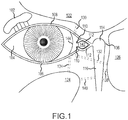
- the invention relates to treatment of conditions of the paranasal sinuses, including with respect to paranasal sinus access implant devices and products and methods including paranasal access implant devices.
- Implantation of an implant device through such a surgically-formed fistula between the lacrimal apparatus and a paranasal sinus has been identified as a technique to provide direct access to the paranasal sinus, and through which a variety of medical treatments and medical procedures may be directed to the paranasal sinus. Though these surgical approaches are widely recognized, millions of patients continue to suffer long-term disability and discomfort. There continues to be a need for effective and convenient techniques to administer drugs directed to treatment of conditions of the paranasal sinuses.
- WO 2012 048278 relates to an implant device, tool, and methods to treatment of paranasal sinuses.
- WO 2009 145755 relates to surface treated implantable articles and related methods.
- Paranasal sinus access implant devices may be configured to be implanted in a human to provide fluid access to a paranasal sinus through an internal passage of such a paranasal sinus access implant device, with the internal passage being accessible through an opening in a head of the paranasal sinus access implant device.
- the head may be configured to be disposed in the lacrimal apparatus in the orbit, for example between the medial canthus and the medial side of the adjacent eyeball, when the paranasal sinus access implant device is implanted to provide fluid access to a paranasal sinus.
- Such paranasal sinus access implant devices have significant potential for performance of medical procedures and treatments of paranasal sinuses, but such potential has not yet been realized.
- Treatment compositions may be delivered to a paranasal sinus through such an implant device by administering eye drops that may then flow through the implant device to a paranasal sinus.
- Fluid administrations may also be made by inserting a needle through the implant device to inject fluid directly into the paranasal sinus and medical procedures may involve passing a medical device through the implant device and into the paranasal sinus.
- implant devices face challenges, including in relation to ease of implantation and control over the implantation procedure, patient comfort in relation to implanted devices and susceptibility of exposed surfaces of implant device to formation of biofilms following implantation.
- a first aspect of the disclosure involves a paranasal sinus access implant device useful for implantation in a human to fluidly connect a lacrimal apparatus to a paranasal sinus through a fistula formed between the lacrimal apparatus and the paranasal sinus.
- a paranasal sinus access implant device may comprise:
- the paranasal sinus access implant device may include one or more material or geometry features, or be associated with one or more material, to at least partially address one of more of the needs noted above.
- the paranasal sinus access implant device may include at least one (any one, any combination of more than one or all) of the following features:
- second material is a term used for convenience of reference and description and does not indicate a distinction from another material that may be used in the implant device, except as specifically identified as such.
- Reference to a second material is often to a material that may be selectively used to enhance a selected portion of the implant device, rather than as a main structural material of construction for the implant device or a portion of the implant device.
- Such a main structural material may sometimes be referred to herein for convenience as a "first material”.
- An implant device may include more than one such "second material” and may include one or more than one such "first material”.
- a material e.g., "first material” or “second material” that is exposed at a surface of an implant device may be referred to interchangeably as an "exposed material”.
- Another aspect of the disclosure involves a method of making a paranasal sinus access implant device of the first aspect that includes at least one such second material.
- the method comprises: providing a preliminary form including a preliminary head structure and a preliminary conduit structure; and forming at least one said second material supported by one or both of the preliminary head structure and the preliminary conduit structure.
- the implant device may be according to the first aspect and may include at least one second material, for example as noted in any one of features (i)-(x) of the first aspect.
- a resulting structure may be used as a final paranasal sinus access implant device product or may be used as new preliminary form for further processing in preparation of a final implant device product.
- Another aspect of the disclosure involves a method for performing a medical procedure in relation to a paranasal sinus and/or administering a treatment composition or performing a medical operation through an implanted implant device directed to the paranasal sinus.
- paranasal sinus access implant device packaged in sterile packaging in contact with a sterile storage liquid.
- the product may include a paranasal sinus access implant device, sterile storage liquid and sterile packaging, wherein the implant device and the storage liquid are disposed within the sterile packaging.
- a method for implanting a paranasal sinus access implant device to fluidly connect a lacrimal apparatus and a paranasal sinus may include removing such an implant device from the sterile packaging of such a product, and implanting the implant device with a proximal end disposed in the lacrimal apparatus and a distal end disposed in the paranasal sinus to fluidly connect the lacrimal apparatus and the paranasal sinus through an internal passage of the implant device.
- paranasal sinus access implant devices are referred to herein as simply implant devices.
- the first material may often have a hardness of at least Shore A 50 durometer, at least Shore A 55 durometer, at least Shore A 60 durometer, at least Shore A 65 durometer, at least Shore A 70 durometer or at least Shore A 75 durometer.
- Such a first material may often have a hardness not greater than Shore A 100 durometer, not greater than Shore A 95 durometer, not greater than Shore A 90 durometer, not greater than Shore A 85 durometer or not greater than Shore A 80 durometer.
- Such a first material may comprise, for example, silicone materials, polyurethane materials, silicone-urethane copolymers, silicone-polycarbonate copolymers, polycarbonate-urethane copolymers and silicone-polycarbonate-urethane copolymers.
- Such first material may be a structural material of construction for the implant device or a portion thereof.
- One preferred silicone material for many implementations includes polydimethylsiloxane as a primary silicone polymer component.
- the first material has a hardness that is larger than the hardness of the second material by at least 10, at least 15, at least 20, at least 25 or at least 30 Shore A durometer units.
- a second material may in some implementations have a hardness that is not larger than Shore A 45 durometer, not larger than Shore A 40 durometer, not larger than Shore A 35 durometer, not larger than Shore A 30 durometer, not larger than Shore A 25 durometer or not larger than Shore A 20 durometer.
- a second material may have a hardness of at least Shore A 5 durometer or at least Shore A 10 durometer.
- One preferred material for use in a second material to form a softer layer over a harder structural material is a silicone-based material, which may be a silicone polymer material or a silicone hydrogel material.
- such a skin portion with a softer second material may be in a layer having a thickness of at least 2 microns, at least 5 microns, or at least 10 microns, or at least 20 microns, and often having a thickness of not larger than 200 microns, not larger than 100 microns, not larger than 50 microns, not larger than 25 microns, not larger than 20 microns or not larger than 15 microns.
- Such a skin portion may have an exposed surface on the implant device (e.g., on the outside of the head or conduit or on walls of the internal passage), or may be covered by a further layer of material, for example a wetting agent or antimicrobial agent.
- Silicone hydrogel materials may be silicone hydrogels such as are used in contact lenses. Such silicone hydrogels may include hydrophilic functionality to counteract hydrophobicity of polysiloxanes. Such hydrophilic functionality may be provided for example, by one or more materials such as pyrrolidone-based functionality (e.g., incorporation of N-vinylpyrrolidone or polyvinylpyrrolidone (PVP), also referred to as poly-N-vinylpyrrolidone or as poly-N-vinyl-2-pyrrolidone, acrylamide-based functionality (e.g. dimethyl acrylamide functionality), glycol-based functionality (e.g., polyethylene glycol) and/or TRIS-based functionality.
- pyrrolidone-based functionality e.g., incorporation of N-vinylpyrrolidone or polyvinylpyrrolidone (PVP), also referred to as poly-N-vinylpyrrolidone or as poly-N-vinyl-2-
- Some example commercial silicone hydrogel material products include balafilcon A (Bausch & Lomb), Iotrafilcon A (CIBA Vision), Iotrafilcon B (CIBA Vision), comfilcon A (CooperVision), senofilcon A (Johnson & Johnson Vision Care) and galyfilcon A (Johnson & Johnson Vision Care).
- such an exposed surface may have an average roughness (Ra) of not larger than 200 nanometers, not larger than 100 nanometers, not larger than 50 nanometers, not larger than 35 nanometers, not larger than 25 nanometers, not larger than 20 nanometers, not larger than 15 nanometers or not larger than 10 nanometers.
- Such an average roughness (Ra) may often be at least 1 nanometer, or at least 2 nanometers or at least 5 nanometers.
- Average roughness Ra may be determined by any suitable analytical technique.
- Average roughness (Ra) may be as determined by optical non-contact profilometry, laser profilometry or atomic force microscopy (AFM). In preferred implementations, the Average roughness (Ra) is as determined by optical non-contact profilometry.
- such a wetting agent may be any polymeric or non-polymeric material that imparts increased hydrophilicity to the exposed surface relative to material of the implant device not including such a wetting agent.
- a wetting agent may be immobile (e.g., through cross-linking or polymer functionalization) or may elute over time (e.g., deposited surface coating or leachable component mixed into material composition).
- the wetting agent may be or include one or more surfactants. Multiple wetting agents may be used together.
- a wetting agent may include multiple components that together provide desired wettability.
- wetting agents include polyvinylpyrrolidone (PVP), polyethylene glycol (PEG), polyethylene oxide, polypropylene oxide, poly(oxyethylene)-poly(oxybutylene) copolymers, hydroxypropylmethylcelluluse (HPMC), polyvinyl alcohol (PVA), poloxamines and hyaluronic acid.
- the wetting agent may be applied as a coating, alone or mixed with another material, may be part of a material of construction, or may be bonded to the surface of the implant device.
- polyethylene glycol may be grafted onto silicone elastomers, such as by atmospheric pressure plasma induced grafting.
- polyethylene glycol may be copolymerized with some silicone materials (e.g., with polydimethyl siloxane).
- silicone materials e.g., with polydimethyl siloxane
- any of these example materials could be deposited on a surface as a coating.
- a wetting agent may be a part of a silicone hydrogel composition at the exposed surface.
- an antimicrobial agent may be any material that has antimicrobial properties (e.g., kills or inhibits growth of or interaction with microorganisms), which may significantly help to prevent formation of biofilms on such exposed surfaces having the antimicrobial agent.
- antimicrobial agent may, for example, be of a type as have been described for use with catheters and/or contact lenses.
- Such an antimicrobial agent may be immobile (e.g., through covalent or strong ionic attachment) or may elute over time (e.g., deposited surface coating or leachable component mixed into material composition). Multiple antimicrobial agents may be used together.
- An antimicrobial agent may include multiple components that together provide antimicrobial activity.
- An antimicrobial agent may be incorporated into or applied to a polymer composition of the implant device that is exposed at an exterior surface of the implant device and/or that is exposed at a surface of the walls of the internal passage.
- An antimicrobial agent may be incorporated into a material prior to using the material to fabricate an implant device or a preliminary form for an implant device, or may be incorporated into the material following formation of a preliminary form.
- An antimicrobial agent may be intermixed with other components, may be in the form of an adhered coating or may be covalently or otherwise attached to a polymeric material (e.g., polysiloxane) or other material of the implant device.
- antimicrobial agents include silver (including for example in the form of silver metal or silver salts and silver oxides), poly(ethylene oxide) (PEO), PEG and antimicrobial peptides. In some implementations, antimicrobial peptides are preferred. Some other example antimicrobial agents include chlorhexidine and/or silver sulfadiazine impregnation, minocycline-rifampicin impregnation, silver-containing nanoparticles impregnation, antimicrobial peptide impregnation or ionic or covalent incorporation (e.g., small cationic peptides, such as for example beta defensins, indolicidin, cecropin A, and magainins, melinines, protattins and lactoferrins).
- Antimicrobial peptides may be deposited on a surface by themselves, or in a mixture with another material (e.g., polymeric material) that helps to immobilize the antimicrobial peptide at the exposed surface.
- an antimicrobial agent may be mixed with a polymeric material that helps to immobilize the antimicrobial agent.
- a polymeric material may be a wetting agent, for example any of the polymeric wetting agents listed previously.
- an antimicrobial peptide may be covalently attached to a polymeric material, for example to silicone materials, according to known methods.
- Such antimicrobial peptides may be bonded directly to exposed material of a preliminary implant device form or may be pre-bonded to a polymer that is then deposited over surfaces of such a preliminary implant device form.
- Such covalent bonding, or attachment may be through the use of one or more coupling agents.
- Coupling agents may be used to provide a stable bond improving affinity and adhesion between dissimilar materials (e.g., between a polymeric material of the implant device and an antimicrobial peptide or other antimicrobial agent).
- Coupling agents may be organic, inorganic and organic-inorganic.
- Some example organic coupling agents include isocyanates, anhydrides, amides, imides, acrylates, chlorotriazines, epoxides and organic acids, and various monomers, polymers and copolymers.
- Some example inorganic coupling agents include silicates.
- Some example organic-inorganic coupling agents include silanes and titanates. Silanes are one preferred group of coupling agents for covalent bonding to silicone and silicone hydrogel materials. In the case of polyethylene oxide as an antimicrobial agent, the polymer may be deposited over an exposed surface of a preliminary implant device form, or may be covalently attached to silicone or silicone hydrogel surfaces.
- an exposed surface of a second material such as in any of features (iv)-(x)
- an exposed surface may be in the form of a continuous or discontinuous surface feature.
- a continuous surface feature it is meant a contiguous surface area of homogeneous surface properties.
- a discontinuous surface feature it is meant a surface area that includes multiple distinct surface areas with different surface properties, such as distinct domains of a surface property (e.g, surface spots of wetting agent, antimicrobial agent, etc.) separated by surface areas having a different surface property (e.g., not including the wetting agent, antimicrobial agent, etc. that is present in the spots).
- the exposed surface of the implant device of the invention has an area of at least 2 square millimeters.
- area of a discontinuous exposed surface it is meant the entire area of exposed surface including all surface phases within the area perimeter to which the distinct domains (e.g., surface spots) extend.
- the exposed surface is in the form of a continuous surface feature.
- the exposed surface may extend for at least 2 millimeters, at least 3 millimeters or at least 5 millimeters or at least 10 millimeters along a longitudinal length of the conduit or even over the entire length or essentially the entire length of the conduit.
- An exposed surface of a second material on the head of an implant device may be disposed toward and/or away from tissue adjacent the fistula (e.g., toward or away from conjunctiva in the orbit) when the implant device is implanted.
- An exposed surface of a second material on the head may extend over all or essentially all of the exterior of the head.
- An exposed surface of a second material on the conduit may extend entirely or essentially entirely around an exterior circumference of at least a portion of the conduit, and may extend over all or essentially all of the exterior of the conduit, including portions of the conduit disposed in the fistula when implanted.
- An exposed surface of a second material may extend over a portion, all or essentially all of the walls of the internal passage of the implant device.
- a single component may provide multiple effects, or multiple components together may provide multiple effects.
- a single component, or multiple components together may serve as both a wetting agent and an antimicrobial agent.
- any one of features (i)-(iii) there may be a plurality of layers that grade from harder to softer toward the surface of the implant device.
- one or more additional material layer may be disposed between the first material and the second material, wherein the intermediate material has a hardness intermediate between the hardness of the first material and the hardness of the second material.
- a material may be disposed between the first material and the second material that has such an intermediate hardness that is at least 10 Shore A durometer units smaller than the hardness of the first material and at least 10 Shore A durometer units larger than the hardness of the second material.
- Such an intermediate material may have a hardness in a range having a lower limit of Shore A 10 durometer, Shore A 15 durometer, Shore A 20 durometer or Shore A 25 durometer and an upper limit of Shore A 50 durometer, Shore A 45 durometer, Shore A 40 durometer or Shore A 35 durometer.
- Such an intermediate material may in some preferred implementations be a silicone material.
- the lubricity agent may be any material that provides enhanced lubricity to such a surface of the internal passage.
- Some example lubricity agents include fluorosilicone materials, very smooth silicone films and poly(p-xylylene) polymers.
- Fluorosilicone materials include siloxane-based polymers including one or more fluoro groups.
- One example fluorosilicone that may be used as a lubricity agent is the copolymer dimethyl methyl trifluoropropylsiloxane.
- An example of a material for a very smooth silicone film providing lubricity is a film made from silane-based materials such as ethyltriacetoxysilane.
- poly (p-xylylene) polymers for providing lubricity include Parylene N or Parylene C polymer products (Para Tech Coating, Inc.).
- a coating of or including such a lubricity material may be formed on walls of the internal passage by any suitable technique, such as deposition from a solution or slurry followed by drying and curing as needed.
- Poly(p-xylylene) polymers may be deposited, for example, by chemical vapor deposition.
- Such a coating of or containing a lubricity agent may have any desired thickness to provide the desired level of lubricity.
- Such a coating may often have a thickness in a range having a lower limit of 1 micron, 2 microns, 5 microns or 10 microns and an upper limit of 200 microns, 100 microns, 50 microns, 25 microns or 15 microns.
- the radiopaque material may be in the form of a radiopaque additive or the radiopaque material may comprise a polymeric material that may have mixed therein a radiopaque additive, for example a particulate filler having a high radiopacity, also referred to as radiodensity.
- a radiopaque additive for example a particulate filler having a high radiopacity, also referred to as radiodensity.
- radiodensity examples include one or more of barium sulfate, titanium metal, tantalum metal, gold metal, platinum metal, iodine, bismuth subcarbonate, bismuth trioxide, bismuth oxychloride and tungsten.
- radiopaque additives may be in the form metal beads or metal wires (e.g., of any of the metals listed above) embedded in a polymer matrix material. Such radiopaque additives may be added into a resin composition as a solid particulate filler, or may be present in solution in an initial composition with the radiopaque material then precipitated during manufacture processing.
- the radiopaque material may have any desired amount of the radiopaque additive to provide a desired level of radiopacity to the material, which will depend in part on the radiodensity properties of the particular radiopaque additive.
- the radiopaque additive may be present in the radiopaque material in an amount in a range having a lower limit of 1 weight %, 5 weight %, 10 weight %, 15 weight % or 20 weight % and an upper limit of 90 weight %, 80 weight %, 70 weight %, 60 weight %, 50 weight % or 40 weight %.
- the radiopaque material may include one or more polymeric components in addition to the radiopaque additive. Such polymeric components may be any of the polymeric materials described herein for making any portion of the implant device. In some implementations, the polymeric material will include a silicone material.
- At least a portion of the conduit including the radiopaque material may have a radiodensity of at least 50 Hounsfield units, at least 100 Hounsfield units, at least 200 Hounsfield units, at least 300 Hounsfield units or at least 400 Hounsfield units.
- Such radiodensity may in various implementations often be not larger than 1000 Hounsfield units, not larger than 900 Hounsfield units, not larger than 800 Hounsfield units or not larger than 700 Hounsfield units.
- a radiopaque portion of the conduit extends for at least 2 millimeters, at least 3 millimeters, at least 4 millimeters, at least 5 millimeters, or at least 6 millimeters along a longitudinal length of the conduit.
- the radiopaque portion of the conduit may include at least such a portion of the longitudinal length of the conduit that includes a distal end of the conduit.
- Such a radiopaque portion may have a proximal end toward the head that is at least 0.5 millimeter, at least 1 millimeter, at least 2 millimeters or at least 3 millimeters distal of the head.
- the entire conduit may be made of radiopaque material.
- the head of the implant device may also be made of radiopaque material.
- at least a portion of the head, and more preferably substantially all of the flanged portions of the head, and even more preferably substantially all of the head has a radiodensity that is smaller than the radiodensity of the radiopaque portion of the conduit, and which may often be a radiodensity of no larger than 75 Hounsfield units, no larger than 60 Hounsfield units, no larger than 40 Hounsfield units, no larger than 30 Hounsfield units or no larger than 20 Hounsfield units.
- the head does not contain a radiopaque additive.
- Having a radiopaque conduit portion permits easy radio imaging of that portion of the conduit during an implantation procedure to ensure proper positioning of the conduit for implantation and/or for long-term monitoring of the positioning of that portion of the conduit following implantation, for example to detect possible migration of the implant device post implantation.
- Having a substantially transparent or translucent head (preferably having both high radiotransparency and high transparency to visible light) makes the implant device less visible (e.g., in the orbit) and therefore more aesthetically pleasing to patients when implanted.
- At least a portion of the head, and preferably at least flanged portions of the head may be visible light translucent or even visible light transparent.
- At least a portion of the head, and preferably at least flanged portions of the head may have a refractive index of not larger than 1.5, not larger than 1.45, not larger than 1.4 or not larger than 1.35.
- the refractive index may often be at least 1.3.
- the rifling may include a spiraling groove, recess, or other surface geometry in a wall of the internal passage, and may extend down a portion or all of the longitudinal length of the internal passage.
- the extension portion may include or be a pleated or accordion-like structure that extends and contracts.
- the sterile packaging, implant device and storage liquid may be, for example, as described for the packaged product aspect of the disclosure.
- a method for making a paranasal sinus access implant device may include forming such a second material over at least a portion of a preliminary head structure, over at least a portion of a preliminary conduit structure or over at least a portion of a preliminary internal passage structure.
- the second material may be formed over an existing first material or a previously provided second material, so that an implant device structure may include multiple second materials with one second material disposed over a prior second material.
- Forming a second material may include modifying the properties of an existing material of a preliminary structure, such as by impregnating an existing material with an additive or reacting an additive at the surface of an existing material.
- Second materials formed during final processing to prepare a final implant product may be exposed at a surface of the implant device product to provide a particular property for the implant device, for example a very smooth surface, hydrophilicity and/or antimicrobial activity.
- providing a preliminary form for use in the method may include modifying a prior preliminary form.
- providing a preliminary form may include molding a polymeric composition in the shape of the preliminary form, which may include curing a resin composition.
- molding techniques may include injection molding, compression molding and transfer molding. Such molding may be performed on an existing structure, such as an extruded tubular shaft forming a base structure for an implant device.
- an implant device e.g., head and anchor protrusions
- the providing a preliminary form on which a second material may be formed may include removing flash from a molded article to provide a smoother surface on which to apply a second material.
- Forming a second material may include any deposition or impregnation technique.
- Some example techniques include dip molding or spray molding to apply a thin layer of a second material.
- Such dip molding or spray molding may include applying a precursor solution with at least one precursor for the second material, drying the precursor solution to leave residual precursor on the preliminary form and optionally curing as necessary residual precursor to form a final polymeric composition of the second material.
- a polymeric composition of the second material may include a thermoset polymer, and the curing may include heating precursor on the preliminary form to cure the thermoset composition.
- the implant device form may be subjected to three dimensional spinning to promote even distribution of deposited material on surfaces of the preliminary implant device on which the material is deposited.
- the forming a second material may include first forming an intermediate material over a desired portion of an implant device structure and then forming a second material over at least a portion of the preliminary material.
- the preliminary material may also be a second material, which may be the same or different than the subsequently applied second material.
- Forming a second material may include forming a preliminary material over a desired portion of the preliminary implant device form and then modifying the preliminary material to form the composition of the desired second material.
- modifying may include adding an additive material (e.g., antimicrobial agent, wetting agent, lubricity agent) to the preliminary material.
- the implant device may be configured to be implanted between the lacrimal apparatus in the orbit and a paranasal sinus (e.g., ethmoid sinus, frontal sinus or maxillary sinus), wherein when so implanted the proximal end is disposed in the lacrimal apparatus within the orbit and the distal end is disposed in the paranasal sinus.
- a paranasal sinus e.g., ethmoid sinus, frontal sinus or maxillary sinus
- the conduit may be configured so that an exterior of the conduit comprises an anchoring surface feature that assists to anchor the implant device when the implant device is implanted.
- the anchoring surface feature includes protrusion areas and recess areas.
- the second minimum wall thickness may occur at a location corresponding with at least one of the recess areas.
- the implant device may be configured so that when implanted the conduit is disposed through the fistula with at least a portion of the recess areas disposed within the fistula and with at least a portion of the protrusion areas disposed in the fistula and engaging tissue exposed within the fistula to anchor the implant device.
- the structural and mechanical characteristics of protrusion occurrences in the protrusion areas may affect anchoring performance of the protrusion areas.
- the height of the protrusion areas relative to the recess areas may affect anchoring effectiveness when the implant device is implanted. A larger height may provide greater anchor effectiveness, but also may involve a larger overall width of the implant device that must be inserted into the fistula.
- the protrusion areas may have a height relative to the recess areas of at least 0.1 millimeter, at least 0.2 millimeter, at least 0.25 millimeter, at least 0.3 millimeter or at least 0.35 millimeter.
- the protrusions areas may have a height relative to the recess areas of no greater than 2 millimeters, no greater than 1.5 millimeter, no greater than 1 millimeter, no greater than 0.75 millimeter, no greater than 0.5 millimeter, no greater than 0.45 millimeter or no greater than 0.4 millimeter.
- the height may be of particular protrusion occurrences relative to adjacent areas of recesses.
- Protrusion occurrences are also referred to herein as anchor protrusions.
- Such anchor protrusions may be configured to flexibly deform when the conduit is inserted through the fistula for implantation, for example to flexibly deform in a direction opposite the direction of insertion when the anchor protrusions contact tissue disposed in the fistula during insertion.
- the anchor protrusions may over time return to their original shape and extend deeper into adjacent tissue to better anchor the implant device.
- the mechanical properties of the anchor protrusions may be influenced by materials of construction.
- Preferred materials of construction for the protrusion areas, and also for the other structured portions of the implant device are polymeric materials.
- the polymeric materials may preferably be medical grade materials. Some preferred polymeric materials are silicones and polyurethanes.
- a structural material of construction should have a rigidity that interacts positively with tissue in the vicinity of the fistula, for example to promote load sharing and good anchoring.
- One preferred material of construction for structural purposes is a polymeric material (e.g.
- the polymeric material has a durometer (Shore A) of about 60, of about 70, of about 80 or of about 100.
- the protrusion occurrences may have a width that tapers, or narrows, in a direction from a base toward a top of the protrusion occurrences, with the base being a portion of a protrusion occurrence disposed toward the internal passage of the conduit and a top of the protrusion occurrence being the extremity of the protrusion occurrence away from the internal passage of the conduit.
- the width may be transverse to the length of the conduit.
- the protrusion occurrences may have a width at the base that is no larger than 2 millimeters, no larger than 1.5 millimeters, no larger than 1.25 millimeters, no larger than 1 millimeter or no larger than 0.75 millimeter.
- One or more of the protrusion occurrences may have a width at the base that is at least 0.2 millimeter, at least 0.3 millimeter, at least 0.5 millimeter, at least 0.75 millimeter or at least 1 millimeter.
- the protrusion occurrences may have a width adjacent the top that is no larger than 0.75 times the width at the base, no larger than 0.5 times the width at the base, or no larger than 0.25 times the width at the base.
- the protrusion occurrences may have a width midway between the base and the top that is no larger than 0.8 times the width of the base, no larger than 0.7 times the width of the base, no larger than 0.6 times the width of the base or no larger than 0.5 times the width at the base.
- the protrusion areas may be provided by a single protrusion occurrence feature located to correspond with the interior of the fistula when the implant device is implanted.
- the protrusion areas include multiple protrusion occurrences spaced on the exterior of the conduit.
- the protrusion occurrences may have a center-to-center spacing, in one or more directions, of at least 0.5 millimeter, at least 0.75 millimeter, at least 1 millimeter, at least 1.25 millimeters, at least 1.4 millimeters or at least 1.75 millimeters.
- the protrusion occurrences may have a center-to-center spacing of no greater than 2.5 millimeters, no greater than 2 millimeters, no greater than 1.75 millimeters or no greater than 1.6 millimeters.
- the protrusion occurrences may have a center-to-center spacing longitudinally along the conduit.
- the protrusion occurrences may have a center-to-center spacing that is at least 0.5 times the base width of the protrusion occurrences, or at least 1 times the base width of the protrusion occurrences or at least 2 times the base width of the protrusion occurrences.
- the protrusion occurrences may have a center-to-center spacing that is no more than 5 times a base width of the protrusion occurrences, no more than 4 times a base width of the protrusion occurrences, no more than 3 times a base width of the protrusion occurrences or no more than 2 times a base width of the protrusion occurrences.
- the protrusion areas may be located on a longitudinal portion of the conduit that includes at least a portion of the conduit that will be disposed within a fistula when the implant device is implanted.
- the protrusion areas may be on a longitudinal portion of the conduit that extends for at least 2 millimeters along the length of the implant device, that extends for at least 3 millimeters along the length of the implant device, that extends for at least 4 millimeters along the length of the implant device, that extends for at least 5 millimeters along the length of the implant device, that extends for at least 6 millimeters along the length of the implant device or that extends for at least 8 millimeters along the length of the implant device.
- a longitudinal portion of the conduit including the protrusion areas may be no longer than 30 millimeters, no longer than 25 millimeters, no longer than 20 millimeters, no longer than 15 millimeters or no longer than 10 millimeters.
- a longitudinal portion of the conduit including the protrusion areas may be disposed at least 2 millimeters from the proximal end of the implant device, at least 3 millimeters from the proximal end of the implant device, at least 4 millimeters from the proximal end of the implant device or at least 6 millimeters from the proximal end of the implant device.
- a longitudinal portion of the conduit including the protrusions may be disposed at least 1 millimeter, at least 2 millimeters, at least 3 millimeters, at least 4 millimeters or at least 6 millimeters from a head of the implant device. Providing significant distance between the head and commencement of the protrusion areas permits the head to better "float" on the surface of tissue, which may enhance patient comfort and device performance.
- the protrusion areas may be disposed along a longitudinal portion of the conduit with the protrusion areas covering no more than 40% of the area along the longitudinal portion of the conduit, 35% of the area along that longitudinal portion of the conduit, no more than 25% of the area along that longitudinal portion of the conduit or not more than 20% of the area along that longitudinal portion of the conduit. Providing significant spacing between protrusion occurrences may permit better engagement of tissue by the anchoring surface feature. Some or all of the protrusion occurrences may be on the second longitudinal portion of the conduit.
- the protrusion areas may comprise at least one circumferential ridge.
- circumferential ridge it is meant a ridge that extends around an entire circumference of the conduit.
- the protrusion areas may comprise at least two, at least three, at least five or at least six circumferential ridges.
- the protrusion areas may in some implementations comprise not more than 20, not more than 15 or not more than 10 circumferential ridges.
- the protrusion areas may comprise a spiral ridge. Such a spiral ridge may extend along a longitudinal portion of the conduit.
- the protrusion areas may comprise a knob or may comprise multiple knobs.
- the anchoring surface feature may comprise a textured surface, with the protrusion areas comprising protruding portions of the textured surface and the recess areas comprising recess portions of the textured surface.
- the length of the implant device may be selected to provide sufficient conduit length for extending through the entire length of the fistula plus any extension distance desired in the lacrimal apparatus proximal to the fistula and in the paranasal sinus distal to the fistula.
- the length of the implant device of the invention is in a range between 8 millimeters and 50 millimeters.
- One preferred range for some implementations when the fistula is between the orbit and the ethmoid sinus or the maxillary sinus is for the length of the implant device and/or for the length of the conduit to be in a range of from 10 millimeters to 30 millimeters, with a range of from 15 millimeters to 25 millimeters being more preferred.
- length of the implant device or the conduit it is meant the dimension longitudinally along the implant device or the conduit, as the case may be, from the proximal end to the distal end of the implant device or the conduit, and may be along a longitudinal axis through the internal passage.
- the length may be a straight line, for example when the internal passage is straight, or the length may be curvilinear or some other shape, for example when the internal passage is not linear.
- transverse to the length the reference is to a right angle to the longitudinal direction of the length at that point (e.g., right angle to a line of the length or to a line tangent to a curve of the length).
- the conduit includes an extension portion that is extendable and contractible to lengthen and shorten the conduit, the implant device that is fully shortened by full contraction and that is fully lengthened by full extension may be within the noted length ranges.
- the implant device may advantageously be designed with a conduit of appropriate width dimensions to fit snuggly within a desired size of fistula.
- the implant device may have a first exterior width dimension defined by a maximum extent of the protrusion areas transverse to the length of the implant device, with the first exterior width being within a range having a lower limit of 0.75 millimeter, 1 millimeter, 1.25 millimeters, 1.5 millimeters, 1.75 millimeters or 2 millimeters and an upper limit of 8 millimeters, 7 millimeters, 6 millimeters, 5 millimeters, 4 millimeters, 3 millimeters, 2.5 millimeters, 2 millimeters or 1.75 millimeters, provided of course that the upper limit must be larger than the lower limit.
- the conduit may have a second width dimension defined by the minimum extent of the recess areas transverse to the length of the implant device, and which second exterior width dimension will be smaller than the first exterior width dimension defined by the protrusion areas.
- the second exterior width dimension defined by the recess areas may be smaller than the first exterior width dimension defined by the protrusion areas by an amount within a range having a lower limit of 0.2 millimeter, 0.25 millimeter, 0.35 millimeter, 0.5 millimeter, 0.6 millimeter or 0.7 millimeter and having an upper limit of 1.5 millimeters, 1 millimeter, 0.9 millimeter or 0.75 millimeter.
- the height of the protrusion areas may be one-half the difference between the first exterior width and the second exterior width. Either one of or each one of the first exterior width and the second exterior width may be the diameter of a circle.
- the implant device may include one or a plurality of side openings through the conduit wall of a distal portion of the conduit, which distal portion may be or include a portion of the conduit that is designed to be disposed within a paranasal sinus when the implant device is implanted to provide fluid access through the implant device to the paranasal sinus.
- the side openings may be open into the internal passage through the conduit and may provide a passage for fluid communication between the internal passage of the implant device and the paranasal sinus even if the distal opening of the internal passage at the distal end of the conduit were to become blocked or restricted for some reason.
- One or more of the side openings may be through a wall of the second longitudinal portion of the conduit, and may be though a wall having the second minimum wall thickness.
- One or more of the side openings may be located within one or more recess areas of an anchoring surface feature of the conduit (e.g., between circumferential ridges).
- an anchoring surface feature of the conduit e.g., between circumferential ridges.
- the implant device may include a head adjacent to the conduit at the proximal end of the implant device.
- the implant device may be configured so that when the implant device is implanted to fluidly connect between a location in the lacrimal apparatus in the orbit and a paranasal sinus (e.g., frontal, ethmoid or maxillary sinus), the head is disposed in the lacrimal apparatus in the orbit, such as in the conjunctival cul-de-sac.
- the head may comprise a flanged tissue engagement surface on a side of the head disposed toward the conduit and configured to engage tissue outside of and adjacent to the fistula when the implant device is implanted.
- the flanged tissue engagement surface may be a flat surface.
- the flanged tissue engagement surface may have non-flat surface features configured to improve seating of the surface against tissue, such as for example to inhibit rotation of the implant device within the fistula after implantation.
- the head may have a face surface opposite the flanged tissue engagement surface and also disposed away from the conduit and disposed away from tissue engaged by the flanged tissue engagement surface when the implant device is implanted.
- the face surface may be substantially flat.
- the face surface may be disposed at the proximal end of the implant device and the internal passage may open at the face surface.
- the separation distance between the face surface and the flanged tissue engagement surface may be in a range having a lower limit of 0.25 millimeter, 0.5 millimeter or 0.75 millimeter and having an upper limit of 2 millimeters, 1.5 millimeters or 1 millimeter. Such separation distance need not be constant across the flanged tissue engagement surface and face surface.
- a maximum separation distance between the face surface and the flanged tissue engagement surface may be referred to as the depth of the head, and such depth may be in a range described above for the separation distance between the face surface and the flanged tissue engagement surface.
- the flanged tissue engagement surface need not be continuous and may be divided into multiple distinct surface portions.
- the flanged tissue engagement surface may include a first flanged portion disposed to one side of the internal passage and a second flanged surface portion disposed to a second side of the internal passage that is opposite the first side.
- Each of the face surface and the flanged tissue engagement surface may have a length dimension that represents a maximum separation distance between points on an outer edge of the respective surface, and may each have a width dimension that is a maximum separation distance between points on the outer edge transverse to the length dimension.
- the length dimensions of the face surface and the flanged tissue engagement surface may be the same or may be different.
- the width dimensions of the face surface and the flanged tissue engagement surface may be the same or may be different.
- the face surface and the flanged tissue engagement surface may have corresponding outer edges.
- the length dimension of any or all of the face surface, the flanged tissue engagement surface and the head may be larger than a first exterior width of the conduit defined by an extent of the protrusion areas transverse to the length of the implant device, when the implant device includes an anchoring surface feature such as summarized above.
- the length dimension of any or all of the face surface, the flanged tissue engagement surface and the head may be in a range having a lower limit of 1 millimeter, 2 millimeters, 2.5 millimeters, 2.75 millimeters, 3 millimeters, 3.5 millimeters, 4 millimeters or 5 millimeters and an upper limit of 10 millimeters, 8 millimeters or 7 millimeters.
- the width dimension of any or all of the face surface, flanged tissue engagement surface and the head may be in a range having a lower limit of 0.5 millimeter, 1 millimeter, 1.5 millimeters, 1.75 millimeters or 2 millimeters and an upper limit of 5 millimeters, 4 millimeters, 3 millimeters, 2.5 millimeters or 2 millimeters, provided as always that the upper limit is larger than the lower limit.
- the length dimension of any or all of the face surface, the flanged tissue engagement surface and the head may be at least 0.5 millimeters, at least 0.75 millimeter, at least 1 millimeter, at least 2 millimeters, at least 3 millimeters or at least 4 millimeters larger than such first exterior width of the conduit defined by an extent of the protrusion areas, when the implant device includes an anchoring surface feature such as summarized above.
- a ratio of the length of any of or all the face surface, the flanged tissue engagement surface and the head to such a first exterior width of the conduit may be at least 1.5 or at least 2. Such a ratio may be smaller than 4, smaller than 3 or smaller than 2.5.
- the width of any or all of the face surface, the flanged tissue engagement surface and the head may be not larger than, or may be smaller than (e.g., by at least 0.1 mm or by at least 0.2 mm), such a first exterior width of the conduit defined by an extent of the protrusion areas, when the implant device includes an anchoring surface feature such as summarized above.
- a ratio of the length dimension to the width dimension for any or all of the face surface, the flanged tissue engagement surface and the head may be in a range having a lower limit of 1, 1.25, 1.5, 2 or 2.5 and an upper limit of 5, 4, 3 or 2.5, provided of course that the upper limit must be larger than the lower limit.
- Having a larger length dimension than width dimension on the head is particularly preferred when the head will be located in the orbit between an eyeball and a medial corner of the palpebral fissure (e.g., between the lacrimal caruncle and the plica semilunaris or through the lacrimal apparatus), because the length dimension may advantageously align in a vertical direction next to the eyeball and will help provide sufficient flanged surface area to effectively anchor the implant device on the proximal end and impede conjunctival tissue from covering the opening into the internal passage of the implant device, compensating for the narrower width. This is particularly advantageous when using polymeric materials of construction as described above.
- the lacrimal apparatus and a paranasal sinus may be in fluid communication through the internal passage of the implant device when the implant device is implanted.
- the conduit may extend from adjacent the proximal end of the implant device.
- the conduit may extend to adjacent the distal end of the implant device.
- the internal passage may have a first end open at the proximal end and a second end open at the distal end, and when the implant device is implanted the first end of the internal passage may open in the lacrimal apparatus and the second end of the internal passage may open in the paranasal sinus.
- the implant device may be configured for implantation with the conduit passing through a fistula between a location in a lacrimal apparatus within the orbit and a paranasal sinus selected from the group consisting of a frontal sinus, an ethmoid sinus, a maxillary sinus and a sphenoid sinus, with a frontal sinus, a maxillary sinus or an ethmoid sinus being preferred, with an ethmoid sinus or a maxillary sinus being more preferred, and with an ethmoid sinus being particularly preferred.
- the implant device may be configured for the conduit to pass through a first paranasal sinus and into a second paranasal sinus in which the distal end of the implant device is disposed when implanted.
- the implant device may provide fluid communication between the lacrimal apparatus and the second paranasal sinus and may or may not also provide fluid communication between the lacrimal apparatus and the second paranasal sinus.
- the portion of the conduit passing through the first paranasal sinus may have an impermeable wall to prevent fluid communication with the first paranasal sinus or may have one or more openings through the wall that provide permeability through the wall and a fluid path for fluid communication to the first paranasal sinus, in which case fluids (e.g., treatment formulations) may be introduced into either one or both of the first and second paranasal sinuses.
- an implant device may be configured to be implanted with a proximal end in the lacrimal apparatus in the orbit and a distal end in an ethmoid sinus with the conduit passing through a frontal sinus or a maxillary sinus.
- a method may be or involve administering a treatment composition to a paranasal sinus through an implant device of the first aspect that fluidly connects the lacrimal apparatus with the paranasal sinus.
- the implant device of the product may include any feature or combination of features disclosed in relation to the first aspect or any other aspect.
- the implant device may be according to the first aspect, or may not be according to the first aspect.
- the implant device may be according to the first aspect including feature (xvi).
- the storage liquid may provide for enhanced wettability of some or all exterior surfaces of the implant device (e.g., surfaces other than the surfaces of the walls of an internal passage within the implant device).
- all exterior surfaces of the implant device may be in contact with the storage liquid.
- Internal passage surfaces may also be in contact with the storage liquid.
- Substantially all surfaces of the implant device may be in contact with the storage liquid.
- the implant device may be immersed in a reservoir of the storage liquid.
- the storage liquid may comprise an aqueous liquid, which may be a buffer solution.
- the storage liquid may include a wetting agent, which may improve hydration of at least a portion of exposed surfaces of the implant device following implantation.
- the implant device includes a head disposed in the lacrimal apparatus when the implant device is implanted, and the wetting agent may improve hydration of exterior surfaces of the head within the lacrimal apparatus.
- the implant device may include a distal portion disposed in the paranasal sinus when the implant device is implanted, and the wetting agent may improve hydration of exterior surface of such distal portion following implantation.
- a wetting agent may include any material that provides enhanced wettability of any such exterior surfaces (e.g., of a head or a distal portion of the implant device) to wetting by biological fluid, for example wetting of head surfaces by lacrimal fluid.
- the wetting agent may be any wetting agent, for example as discussed above.
- One preferred wetting agent is hyaluronic acid.
- the sterile packaging may include any sterile barrier enclosure, for example in the form of a sealed bag, pouch or tray.
- a packaged product may include a plurality of such implant devices, with the sterile packaging including a plurality of sealed compartments each having disposed therein an implant device in contact with storage liquid.
- the sterile packaging may include a multi-compartment tray comprising such an implant device sealed within each of a plurality of such compartments of the tray. Each such compartment may be sealed so that each such sealed compartment is individually unsealable to remove an implant device from a compartment without unsealing other compartments.
- the sterile packaging may include a multi-compartment tray (e.g., of a plastic material) with compartments sealed with a foil lid.
- the implant device may have at least a residual portion of the storage liquid, which may include at least a portion of a wetting agent, covering at least a portion of the implant device.
- lacrimal apparatus and “lacrimal system” are used interchangeably herein to refer to the collection of physiological components that accomplish the production and secretion of lacrimal fluid to lubricate the eyeball, containment of lacrimal fluid in a reservoir of lacrimal fluid in the orbit and drainage of lacrimal fluid from the orbit to the nasal cavity.
- the lacrimal apparatus includes the lacrimal glands, the tear drainage system and the reservoir of lacrimal fluid located between the lacrimal glands and the tear drainage system.
- the reservoir of lacrimal fluid includes the eyelid margins and the conjunctival sac (and including the pool of tears in the lower conjunctival cul-de-sac that is sometimes referred to as the lacrimal lake).
- the tear drainage system includes the puncta, canaliculi and nasolacrimal duct (including the so-called lacrimal sac located at the top of the nasolacrimal duct) through which excess tears drain to Hasner's valve and into the nasal cavity.
- Figure 1 shows generally the lacrimal apparatus.
- Lacrimal fluid is produced and secreted from lacrimal glands 102 to lubricate the surface of the eyeball 104 disposed within the orbit.
- Lacrimal fluid forms a coating over the eyeball 104 and is generally contained within the conjunctival sac (the space between the lower eyelid 106, upper eyelid 108 and eyeball 104 that is lined by the conjunctiva).
- Excess lacrimal fluid is conducted to the vicinity of the medial canthus (medial corner of the eye) and drains through the lacrimal puncta 110 into the lacrimal canaliculi 112 and into the lacrimal sac 114 of the nasolacrimal duct 116.
- the lacrimal fluid then drains from the nasolacrimal duct 116 through Hasner's valve and into the nasal cavity.
- a fistula between the lacrimal apparatus and a paranasal sinus refers to an artificially-created passage that fluidly connects the lacrimal apparatus with a paranasal sinus. Such a fistula may be surgically created.
- the paranasal sinuses include the frontal sinuses, maxillary sinuses, ethmoid sinuses and sphenoid sinuses, which are cavities contained within frontal, maxilla, ethmoid and sphenoid bones, respectively. The paranasal sinuses drain into the nasal cavity.
- Figure 1 also shows the general proximity of the frontal sinus 122, maxillary sinus 124 and ethmoid sinus 126 relative to features of the lacrimal apparatus and some example fistula routes shown by dashed lines.
- a first example fistula route 130 is from the orbit to the frontal sinus 122.
- a second example fistula route 132 is from the orbit to the ethmoid sinus 126.
- a third example fistula route 134 is from the orbit to the maxillary sinus 124.
- a fourth example fistula route 136 is from the lacrimal sac 114 at the top of the nasolacrimal duct 116 to the ethmoid sinus 126.
- a fifth example fistula route 138 is from the nasolacrimal duct 116 at a location below the lacrimal sac 114 to the ethmoid sinus 126.
- a sixth example fistula route 140 is from the nasolacrimal duct 116 at a location below the lacrimal sac 114 to the maxillary sinus 124.
- the example fistula routes shown in Figure 1 are for purposes of general illustration only and not to show precise locations where a fistula might be formed to connect a part of the lacrimal apparatus with the corresponding paranasal sinus.
- example fistula routes to the sphenoid sinus include from the orbit to the sphenoid sinus and from the nasolacrimal duct 116 to the sphenoid sinus.
- Figure 2 shows an implant device 700 with a head 702 and a conduit 704.
- the conduit 704 includes a first longitudinal portion 706 and a second longitudinal portion 708 disposed distal of the first longitudinal portion 706.
- the first longitudinal portion 706 includes a smooth exterior surface and the second longitudinal portion 708 includes an anchoring surface feature including anchor protrusions 710, in the form of spaced circumferential ridges, and recess areas 712 between the anchor protrusions 710.
- the length of the first longitudinal portion 706, located before the beginning of the anchoring surface feature of the second longitudinal portion 708, may advantageously be disposed in conjunctival tissue adjacent the head 702 when implanted to "float" for patient comfort and to facilitate performance of post-implantation medical procedures without disruption of implant anchor stability.
- the anchoring features of the second longitudinal portion 708 may advantageously be located a distance from the head 702 so that one or more of the anchor protrusions 710 are located in the vicinity of the paranasal sinus bone wall that is penetrated by the implant device 700 when implanted, preferably with one or more of the anchor protrusions 710 disposed on each side of the bone.
- the exterior width of the conduit 704 is substantially the same for the whole length of the first longitudinal portion 706 and in the recess areas 712 of the second longitudinal portion 708.
- the conduit 704 has a circular cross-section, so that the exterior width of the conduit 704 at any location along the conduit 704 is represented by the diameter of the circular cross-section of the conduit 704 at that location.
- the implant device 700 has a length 714 from a proximal end 716 to a distal end 718 of the implant device 700.
- the beginning of the second longitudinal portion 708 is located a distance 720 distal from the proximal end 716.
- the anchor protrusions 710 have a width 722 at the base of the anchor protrusions 710 and a height 724 above the adjacent recess areas 712.
- the anchor protrusions 710 are spaced on a center-to-center spacing 726.
- the conduit 704 has a maximum exterior width 728 corresponding with the tops of the anchor protrusions 710, equal to the diameter of the circle of the cross-section through the conduit 704 at the top of the anchor protrusions 710.
- the conduit 704 has a minimum exterior width 730 along the length of the first longitudinal portion 706 and in the recess areas 712 of the second longitudinal portion 708 of the conduit 704, and which is equal to the diameter of the circular cross-section at those locations.
- the head 702 has a length dimension 732, a width dimension 734 and a depth dimension 736.
- the implant device 700 has an internal passage 738 extending between the proximal end 716 and the distal end 718 and through the length of the conduit 704.
- the internal passage 738 has a width 740, which in this embodiment is equal to a diameter of the circular cross-section of the internal passage 738.
- Figure 3 shows the same implant device 700 as shown in Figure 2 with some exemplary dimensions, in millimeters, for one nonlimiting example for a configuration for the implant device 700.
- Figure 4 shows an implant device 800 that is similar to the implant device 700 shown in Figures 2 and 3 , except including a first longitudinal portion of a conduit having a thicker wall than recess areas of the anchoring surface feature of a second longitudinal portion of the conduit.
- the thicker wall in the first longitudinal portion of the conduit provides added rigidity to that portion of the conduit to facilitate pushing the implant device 800 into place during an implantation procedure, while the thinner wall in the recess areas of the second longitudinal portion of the conduit permit that portion to more easily deform and fit through a fistula during implantation and then to expand to engage tissue and anchor the implant device 800.
- the implant device 800 includes a head 802 and a conduit 804.
- the conduit 804 has a first longitudinal portion 806 and a second longitudinal portion 808 located distal of the first longitudinal portion 806.
- the first longitudinal portion 806 includes a substantially smooth exterior surface with a substantially constant exterior width, which is the diameter of the circular cross-section of the conduit 804 along the first longitudinal portion 806.
- the second longitudinal portion 808 includes an anchoring surface feature including anchor protrusions 810, in the form of circumferential ridges, and recess areas 812 in the spaces between the anchor protrusions 810.
- Various dimensions of the implant device 802 are illustrated in Figure 4 , similar to the illustration provided for the implant device 700 in Figure 2 .
- the implant device 800 has a length 814 from a proximal end 816 to a distal end 818 of the implant device 800.
- the beginning of the second longitudinal portion 808 is located a distance 820 distal of the proximal end 816.
- the anchor protrusions have a width 822 at the base and a height 824 above the adjacent recess areas 812.
- the anchor protrusions are spaced on a center-to-center spacing 826.
- the conduit 804, and also the second longitudinal portion 808, has a maximum exterior width 828 occurring at the tops of the anchor protrusions 810, and equal to the diameter of the circular cross-section of the conduit 804 through the tops of the anchor protrusions 810.
- the conduit 804, and the second longitudinal portion 808, of the conduit 804 have a minimum exterior width 830 located at the recess areas 812.
- the head 802 has a length dimension 832, a width dimension 834 and a depth dimension 836.
- the implant device 800 has an internal passage 838 extending between the proximal end 816 and the distal end 818 and through the length of the conduit 804.
- the internal passage 838 has a width 840, which in the embodiment shown in Figure 4 is equal to a diameter of the circular cross-section of the internal passage 838.
- the wall thickness of the conduit 804 (thickness of the wall between the internal passage 838 and the exterior surface of the conduit 804) is greater along the first longitudinal portion 806 than in the recess areas 812 of the second longitudinal portion 808.
- the internal passage 838 has a constant width along the length of the conduit 804, such that the greater wall thickness of the conduit 804 along the first longitudinal portion 806 results in an exterior width 842 that is larger than the minimum exterior width 830 in the recess areas 812.
- the maximum exterior width 828 at the anchor protrusions 810 is larger than the exterior width 842 along the first longitudinal portion 806.
- Figure 5 shows some exemplary dimensions, in millimeters, for one nonlimiting example for a configuration of the implant device 800.
- Figure 6 shows a variation on the implant device 800 of Figure 4 .
- the implant device 800' variation of Figure 6 has the same features as the implant device 800 of Figure 4 , except that the implant device 800' includes a plurality of side openings 850 (which may also be referred to as holes, apertures or ports) through the wall of a distal portion of the conduit 804'.
- the side openings 850 may be located on a portion of the conduit wall that would be disposed in the paranasal sinus when the implant device 800' is implanted, such that the side openings 850 may provide a passage for fluid communication between the internal passage of the implant device 800' and the paranasal sinus even if the distal opening of the internal passage at the distal end of the conduit 804' were to become blocked or restricted for some reason.
- the side openings 850 are located in a recess area between a pair of circumferential ridges of an anchoring surface feature of the conduit 804'.
- Figure 6 shows the side openings 850 located in only one recess area between one pair of circumferential ridges, but one or more similar side openings could also or alternatively be located in a more proximal recess area between a different pair of the circumferential ridges.
- FIG 7 shows another example variation on the implant device 800 of Figure 4 .
- the implant device 800" variation shown in Figure 7 has the same general features as the implant device 800 of Figure 4 , but with a different head design.
- the head 802" shown in Figure 7 has flanged portions with a distal side having concave surfaces 852 disposed towards the distal end of the implant device 800".
- the flanged portions of the head 802" have a proximal side with convex surfaces 854 disposed away from the distal end of the implant device 800".
- the concave surfaces 852 may provide an advantage of better conforming with soft tissue within the orbit engaged by the distal side of the flanged head portions when the implant device 800" is implanted to fluidly connect the lacrimal apparatus in the orbit with a paranasal sinus.
- the convex surfaces 854 also may better conform with the surface of such soft tissue when the implant device 800" is implanted.
- the head 802" may thus help reduce possibility for a foreign body sensation when the implant device 800" is implanted.
- FIG 8 shows another example variation on the implant device 800 of Figure 4 .
- the implant device 800'" variation shown in Figure 8 has the same general features as the implant device 800 of Figure 4 , but includes a conduit 804'" including a radiopaque portion 856 extending over a significant length of the conduit 804"'.
- the conduit 804'" also includes a radiotransparent portion 858 located adjacent the proximal end of the conduit 804"'.
- the head 802"' is also radiotransparent.
- the head 802"' in particular is preferably clear and substantially transparent or translucent to visible light so that when the implant device 800"' is implanted with the head 802"' disposed in the orbit, the head 802"' is not highly visible.
- the radiopaque portion 856 of the conduit 804"' may be easily imaged by radiation, for example by x-ray imaging, to verify the positioning of the conduit 804"' in a patient's body when the implant device 800'" is implanted or at any time post implantation, for example to verify proper implant placement.
- an implant device could be made to be entirely radiopaque, however such a variation may be not preferred for some applications due to enhanced visibility of the head 802"', which may be generally less aesthetically pleasing to patients in which the implant device is implanted.
- the implant device 800'" may be made, for example, by introducing a radiotransparent resin composition into a proximal end of a mold and a radiopaque resin composition into a distal end of the mold, with an interface between the different resin compositions forming at an intermediate location in the mold based on the relative proportions of the different resin compositions introduced into the mold.
- a radiopaque portion 856 may be a resin composition including a radiopaque agent (e.g., particulate radiopaque filler), while the radiotransparent composition may include the same or a different resin (e.g., silicone or polyurethane resin).
- Figure 9 shows a preliminary form 860 including a preliminary head structure 862 and a preliminary conduit structure 864.
- the preliminary conduit structure 864 includes a first longitudinal portion 866 and a second longitudinal portion 868.
- First longitudinal portion 866 has a substantially smooth exterior surface with a substantially constant exterior width of circular cross-section.
- the second longitudinal portion 868 includes an anchoring surface feature including anchor protrusions 870, in the form of circumferential ridges, and recess areas 872 in the spaces between the anchor protrusions 870.
- the first longitudinal portion 866 of the preliminary conduit 864 may have a larger minimum wall thickness than the second longitudinal portion 868.
- the preliminary conduit 864 is illustrated with features substantially as described with respect to the conduit of the implant device shown in Figure 4 , but could be of a different design, for example with one or more features shown in any of Figures 2-3 , 6-8 or 16-26 .
- the preliminary head structure 862 is also illustrated with features substantially as shown in Figure 4 , but could be of a different design, for example with one or more features shown in any of Figures 2-3 , 6-8 or 16-26 .
- the preliminary head structure 862 includes flash 874 around the perimeter of the preliminary head 862.
- the preliminary implant device form 860 may be an initial mold product (e.g., from injection molding, compression molding or transfer molding) of one or more resin compositions (e.g., silicone or polyurethane resin), and the flash 874 may be formed at a joint between parts of the mold. Presence of such flash 874 may contribute to a patient experiencing a foreign body sensation when implanted. Such flash 874 may be removed to smooth the surface of the head and reduce potential for such a foreign body sensation and may also help to reduce potential for biofilm formation on the smoother surface. Such removal of the flash 874 may be effected by any removed technique, for example by trimming, cryogenic tumbling or laser ablation.
- Figure 10 shows a modified implant device form 860' with a modified head structure 862' after removal of the flash 874 from the preliminary implant device form 860 of Figure 9 .
- the preliminary conduit 864 is unaltered in Figure 10 .
- the modified implant device 860' may be used as a final implant device product, or may be used as a further preliminary form that is further modified.
- the modified head structure 862' may be further modified by forming a thin layer of softer material over the modified head structure 862', for example a layer of a silicone material that is softer than the initial structural material of the preliminary head structure 862.
- a layer of softer material may be formed, for example, by dip molding or spray molding a softer layer of material on top of the modified head structure 862'.
- FIG 11 shows an example following formation of such a softer material layer, with the implant device form now designated as a further modified form 860".
- the modified implant device form 860" includes a modified head structure 862" that is slightly enlarged by addition of such a thin layer of softer material.
- the modified head structure 862" includes a layer of softer material 876 formed over original structural material 878 of the original head form 862 of Figure 9 .
- the presence of the softer material 876 may further enhance compatibility with soft tissue within the orbit when implanted, which may further help to avoid a foreign body sensation following implantation.
- such a carefully applied layer of softer material 876 may have a significantly smoother exterior surface than the exterior surface of the original preliminary head structure 862 of Figure 9 or the modified head structure 862' of Figure 10 .
- Such smoother exterior surface may further assist in reducing potential for a foreign body sensation following implantation and may also reduce potential for biofilm formation on exposed surfaces of the modified head structure 862".
- the modified implant device form 860" may be used as a final implant device product, or may be used as a further preliminary form that is further modified.
- the conduit may be similarly modified by forming a thin layer of softer material over a portion of the preliminary conduit structure 864.
- Figure 13 shows a further modified implant device form 860'" including a modified conduit structure 864' including such a layer of softer material formed over a distal portion of the initial preliminary conduit structure 864 shown in Figure 9 .
- the modified distal portion of the modified conduit structure 864' includes a layer of softer material 880 over the original structural material 882 of the initial preliminary conduit structure 864.
- Such a layer 880 could, for example, be of a silicone material that is softer than the initial structural material of the preliminary conduit structure 864. Such a layer of softer material 880 may advantageously be provided only on a distal portion of the conduit that extends into the paranasal sinus when the implant device is implanted, although such a softer layer could be placed over other portions of the conduit as well if desired.
- the harder structural material 882 would remain exposed along the portion of the conduit that passes through the wall of the paranasal bone (e.g., the ethmoid bone) and that engages soft tissue immediately proximal of such bone. The harder structural material 882 provides better mechanical interaction for anchoring an implant device.
- the modified implant device form 860"' may be used as a final implant device product or may be used as a further preliminary form that is further modified.
- Such a modified head form 862" or modified conduit form 864' may be further modified, for example, by applying one or more additive materials to one or both of the softer material layers 876 and 880.
- additive materials may include, for example, a wetting agent, an antimicrobial agent and/or other additive materials.
- Figure 15 shows the conduit form 860'" of Figure 13 after further modification to apply an additive material to each of the layers of softer material 876 and 880.
- Figure 15 shows the further modified implant device form 860"" with shading on a further modified head structure 862'" and a further modified conduit structure 864" to show addition of such an additive material to the layer of softer material 876 and the layer of softer material 880.
- a wetting agent e.g., polyvinylpyrrolidone, polyethylene glycol or hyaluronic acid
- a wetting agent may be deposited from a solution, for example, by dipping or spraying, followed by drying and optionally heating to cure the composition or to improve adhesion of the wetting agent.
- Addition of an antimicrobial agent may further assist to reduce potential formation of biofilms on the modified head form 862'" and the distal portion of the modified conduit form 864".
- a silver salt may be deposited from the solution applied by dripping or spraying, followed by drying and optionally heating.
- silver metal may be deposited by physical vapor deposition or chemical vapor deposition.
- an antimicrobial peptide may be deposited from a solution or slurry or may be covalently bonded to exposed polymer (e.g., silicone) of one or both of the softer material layers 876 and 880.
- a polymeric antimicrobial agent e.g., polyethylene oxide or polyethylene glycol
- a wetting agent e.g., PVP, PEG, hyaluronic acid
- antimicrobial agent e.g., a polymeric antimicrobial agent and/or an antimicrobial peptide
- Figure 16 shows an initial implant device form 884 including a head 886 and a conduit 888 and having a preliminary internal passage 890 passing through the head 886 and the conduit 888.
- the preliminary implant device form 884 is illustrated as having features of the implant device of Figure 4 , but it could alternatively be of a different design, for example with one or more features shown in any of Figures 2-3 , 6-15 or 18-26 .
- Figure 17 shows a modified implant device form 884' with a modified internal passage structure 890' following formation of a thin layer of or including a lubricity agent.
- Such a thin layer of lubricity material may be formed, for example, by casting a film of or including the lubricity agent or precursor therefore onto the walls of the preliminary internal passage 890 and then curing the cast film as necessary to form a final coating with high lubricity.
- a lubricity agent may, for example, be a fluorosilicone polymer or a very smooth silicone film (e.g., similar to layers 876 and 880).
- One example silicone material for such a smooth film is a film formed by reaction of ethyltriacetoxysilane.
- the layers of lubricity material may be deposited by chemical vapor deposition, for example a poly(p-xylylene) polymer (e.g., Parylene N or Parylene C).
- a poly(p-xylylene) polymer e.g., Parylene N or Parylene C
- An internal passage could also be treated to apply an antimicrobial agent, with or without applying a lubricity agent, similar to as described in relation to Figures 14-15 .
- FIG 18 showing a cross-section of an implant device 892 having a head 894 and a conduit 896 and with an internal passage 897 extending through the head 894 and the conduit 896.
- the implant device 892 is illustrated with features of the implant device of Figure 4 , but it could be of a different design, for example including one or more features shown in any of Figures 2-3 , 6-17 or 19-26 .
- the internal passage 897 of the implant device 892 has a surface geometry including rifling 898 in the form of a spiraling recess extending the along the length of the internal passage 897.
- FIG. 19 illustrating one example of an extension portion on a conduit that is extendable and collapsible, or contractible, to lengthen and shorten, respectively, a longitudinal length of a distal portion of a conduit of an implant device.
- an implant device 500 includes a head 502 and a conduit 504, and which may have a design similar to that or including any features of an implant device shown in any of Figures 2-18 or 21-26 , except that on a distal portion of the conduit 504, the implant device 500 includes an extension portion 506 of a pleated, or accordion, structure that may be extended and contracted to lengthen and shorten, respectively, a distal portion of the conduit 504 that is to be disposed within the paranasal sinus when the implant device 500 is implanted.
- the extension portion 506 is shown in a fully contracted, or collapsed, configuration in Figure 19 and in a fully extended configuration in Figure 20 .
- FIGS 21-26 show another embodiment of a paranasal sinus access implant device.
- the implant device 510 has a head 512 and a conduit 514 with a first longitudinal portion 516 having a larger minimum wall thickness and a second longitudinal portion 519 having a smaller minimum wall thickness.
- the implant device 510 has seven anchor protrusions 518 in the form of circumferential ridges and recess areas 520 between pairs of adjacent ridges.
- the implant device 510 has a proximal end 522 and a distal end 524 and an internal passage 526 that extends from the proximal end 522 through the head 512 and the conduit 514 to the distal end 524.
- Various details and dimensions for the implant device 510 are shown in Figures 22-26 .
- the implant device 510 of Figures 21-26 has more circumferential ridges with a closer spacing between the ridges and a smaller head, and with the head 512 having concave surfaces 528 on the distal side of the flanged portions of the head 512 and having convex surfaces 530 on the proximal side of the flanged portions of the head 512 (seen best in Figure 26 ).
- the concave surfaces 528 on each of the flanged portions of the head are in the form of a cup-shaped depression that may trap and hold liquid between soft tissue (e.g., in the orbit) and the concave surfaces 528 to maintain a hydration buffer between the flanged portions of the head 512 and the soft tissue when the implant device is implanted.
- the conduit 514 may be made of a radiopaque material.
- a radiopaque material for example a polymer composition containing a filler of particles of a radiopaque material.
- the conduit 514 may be made of a 70-90 Shore A durometer silicone containing 20-30 % of barium sulfate particles.
- the head 512 may be made of a similar polymer material, but not containing radiopaque material, so that the head 512 may be clear and transparent.
- the head 512, conduit 514 and/or internal passage 526 may be modified in any manner as discussed previously, for example with respect to any one or more of Figures 9-17 .
- Figure 27 shows an example of an implant device with a conduit passing through a fistula formed from the orbit subconjunctivally between the lacrimal caruncle 142 and the plica semilunaris 144, and showing an example location for the head 304 of the implant device disposed in the orbit, shown for example between the lacrimal caruncle 142 and the plica semilunaris 144.
- Figures 28 and 29 show an example implementation of an implant device 630 to fluidly connect between the lacrimal apparatus in the orbit and the ethmoid sinus 126.
- the implant device 630 is mounted on a surgical tool, in the form of an implant tool 624.
- the implant tool may also be referred to as a carrier tool.
- the implant tool 624 includes a hollow working member 626 and a hand-manipulable handle 628.
- the implantation tool 624 is shown with the hollow working member 626 advanced through a previously formed fistula between the lacrimal apparatus in the orbit and the paranasal sinus 126.
- the working member 626 may also be referred to as a carrier member.
- the implant tool 624 includes an internal passage passing through the handle 628 and the hollow working member 626. As shown in Figure 28 , a guide wire 620 has been threaded through the internal passage of the implant tool 624 to guide the hollow working member 626 to and through the fistula and into the ethmoid sinus 126.
- the implant device 630 is mounted on the hollow working member 626 of the implant tool 624. Figure 28 shows the implant tool 624 advanced to a point where the distal end of the implant device 630 is in the vicinity of the proximal end of the fistula opening into the conjunctival sac.
- the implant device 630 may be advanced into the fistula with a head of the implant device 630 disposed adjacent the conjunctiva in the conjunctival sac and a distal end of the implant device 630 extending into the ethmoid sinus 126.
- a surgeon may slide the implant device 630 down the hollow working member 626 for placement through the fistula for implantation or the surgeon may advance the handle 628 to have the handle push the implant device 630 into the fistula for implant placement.
- the outside diameter of the hollow working member 626 may be sized to closely fit within the inside diameter of the implant device 630 to help prevent the implant device 630 from bunching-up and laterally deforming as the implant device is pushed into the fistula.
- the handle 628 and the hollow working member 626 form a carrier for the implant device 630.
- the handle 628 may be retracted and the hollow working member 626 disengaged from the implant device 630 after the implant device has been appropriately positioned for implantation through the fistula.
- Figure 29 shows the implant device 630 as implanted and following disengagement of the hollow working member 626 of the implantation tool 624.
- a head 632 at the proximal end of the implant device 630 is located adjacent the conjunctiva in the conjunctival sac within the lacrimal apparatus in the orbit, and the conduit passes through the fistula across tissue including conjunctiva and a wall of the ethmoid bone in which the ethmoid sinus 126 is located.
- a distal end 634 of the implant device 630 is located in the ethmoid sinus 126.
- Some anchor protrusions 636 of the conduit of the implant device 630 are disposed within the fistula to engage tissue and help anchor the implant device 630.
- the implant device 630 may be used to provide access to the ethmoid sinus 126 to perform medical procedures or treatments, for example to administer a treatment composition to the ethmoid sinus or to aspirate fluid from the ethmoid sinus.
- a variety of medical treatments and procedures may be performed through a paranasal sinus access implant device implanted to provide access to a paranasal sinus.
- Fluid treatment compositions may be administered to a paranasal sinus through the implant device.
- Fluid may be aspirated from a paranasal sinus through the implant device.
- One or more medical devices may be inserted into the paranasal sinus through the implant device.
Claims (20)
- Dispositif d'implant d'accès aux sinus paranasaux (500, 510, 630, 700, 800, 800', 800", 800"', 860, 860', 860", 860"', 860"", 884, 884', 892) utile pour l'implantation chez un humain afin de relier fluidiquement un appareil lacrymal à un sinus paranasal à travers une fistule formée entre l'appareil lacrymal et le sinus paranasal, le dispositif d'implant (500, 510, 630, 700, 800, 800', 800", 800"', 860, 860', 860", 860"', 860"", 884, 884', 892) comprenant :une extrémité proximale (522, 716, 816) au niveau d'une première extrémité longitudinale du dispositif à disposer dans l'appareil lacrymal lorsque le dispositif est implanté et une extrémité distale (524, 634, 718, 818) au niveau d'une deuxième extrémité longitudinale du dispositif à disposer dans le sinus paranasal lorsque le dispositif est implanté ;une longueur longitudinale le long du dispositif d'implant (500, 510, 630, 700, 800, 800', 800", 800"', 860, 860', 860", 860'", 860"", 884, 884', 892) entre l'extrémité proximale (522, 716, 816) et l'extrémité distale (524, 634, 718, 818) dans une plage de 8 millimètres à 50 millimètres ;un conduit (504, 514, 704, 804, 804', 804"', 864, 864', 864", 888, 896), situé entre l'extrémité proximale (522, 716, 816) et l'extrémité distale (524, 634, 718, 818), destiné à être disposé à travers une fistule entre l'appareil lacrymal et le sinus paranasal lorsque le dispositif est implanté, le conduit (504, 514, 704, 804, 804', 804'", 864, 864', 864", 888, 896) comprenant une partie distale à disposer dans le sinus paranasal lorsque le dispositif d'implant (500, 510, 630, 700, 800, 800', 800", 800"', 860, 860', 860", 860"', 860"", 884, 884', 892) est implanté :une tête (304, 502, 512, 632, 702, 802, 802", 802"', 862, 862', 862", 862'", 886, 894) située à proximité du conduit (504, 514, 704, 804, 804', 804'", 864, 864', 864", 888, 896), à disposer dans l'appareil lacrymal lorsque le dispositif est implanté ;un passage interne (526, 738, 838, 890, 890', 897) à travers la tête (304, 502, 512, 632, 702, 802, 802", 802"', 862, 862', 862", 862'", 886, 894) et le conduit (504, 514, 704, 804, 804', 804'", 864, 864', 864", 888, 896), pour fournir un chemin de communication fluide entre l'appareil lacrymal et le sinus paranasal lorsque le dispositif est implanté, le passage interne (526, 738, 838, 890, 890', 897) ayant une largeur (740, 840) à travers au moins une partie du conduit (504, 514, 704, 804, 804', 804'", 864, 864', 864", 888, 896) dans une plage de 0,25 millimètre à 5 millimètres ; etcaractérisé en ce que :
au moins l'une de la tête (304, 502, 512, 632, 702, 802, 802", 802"', 862, 862', 862", 862'", 886, 894) et de la partie distale du conduit (504, 514, 704, 804, 804', 804"', 864, 864', 864", 888, 896) comprend une surface exposée sur une surface continue d'au moins 2 millimètres carrés de matériau exposé, la surface exposée ayant une rugosité moyenne (Ra) non supérieure à 200 nanomètres. - Dispositif d'implant (500, 510, 630, 700, 800, 800', 800", 800'", 860, 860', 860", 860'", 860"", 884, 884', 892) selon la revendication 1, ladite surface exposée :étant sur un extérieur de la partie distale du conduit (504, 514, 704, 804, 804', 804'", 864, 864', 864", 888, 896), laquelle partie distale du conduit (504, 514, 704, 804, 804', 804''', 864, 864', 864", 888, 896) étant à disposer dans le sinus paranasal lorsque le dispositif d'implant (500, 510, 630, 700, 800, 800', 800", 800''', 860, 860', 860", 860''', 860"", 884, 884', 892) est implanté ;s'étendant sur au moins 2 millimètres le long d'une longueur longitudinale du conduit (504, 514, 704, 804, 804', 804''', 864, 864', 864", 888, 896) adjacente à l'extrémité distale (524, 634, 718, 818) ; ets'étendant entièrement autour d'une circonférence extérieure de la partie distale du conduit (504, 514, 704, 804, 804', 804''', 864, 864', 864", 888, 896).
- Dispositif d'implant (500, 510, 630, 700, 800, 800', 800", 800''', 860, 860', 860", 860''', 860'''', 884, 884', 892) selon l'une ou l'autre des revendications 1 ou 2, ladite surface exposée étant sur une surface de la tête (304, 502, 512, 632, 702, 802, 802", 802''', 862, 862', 862", 862''', 886, 894) pour être disposée vers un tissu adjacent à la fistule lorsque le dispositif d'implant (500, 510, 630, 700, 800, 800', 800", 800''', 860, 860', 860", 860''', 860"", 884, 884', 892) est implanté.
- Dispositif d'implant (500, 510, 630, 700, 800, 800', 800", 800''', 860, 860', 860", 860''', 860'''', 884, 884', 892) selon l'une quelconque des revendications 1 à 3, ladite surface exposée étant sur une surface de la tête (304, 502, 512, 632, 702, 802, 802", 802''', 862, 862', 862", 862''', 886, 894) pour être disposée à l'écart du tissu adjacent à la fistule lorsque le dispositif d'implant (500, 510, 630, 700, 800, 800', 800", 800''', 860, 860', 860", 860''', 860"", 884, 884', 892) est implanté.
- Dispositif d'implant (500, 510, 630, 700, 800, 800', 800", 800''', 860, 860', 860", 860''', 860'''', 884, 884', 892) selon l'une quelconque des revendications 1 à 4, le Ra n'étant pas supérieur à 100 nanomètres et ladite surface exposée s'étendant sur pratiquement tout l'extérieur de la tête (304, 502, 512, 632, 702, 802, 802", 802''', 862, 862', 862", 862''', 886, 894).
- Dispositif d'implant (500, 510, 630, 700, 800, 800', 800", 800''', 860, 860', 860", 860''', 860'''', 884, 884', 892) selon l'une ou l'autre des revendications 4 ou 5, le matériau exposé ayant une dureté Shore A au duromètre non supérieure à 45.
- Dispositif d'implant (500, 510, 630, 700, 800, 800', 800", 800''', 860, 860', 860", 860''', 860"", 884, 884', 892) selon l'une quelconque des revendications 1 à 6, ladite surface exposée s'étendant sur pratiquement tout l'extérieur du dispositif d'implant (500, 510, 630, 700, 800, 800', 800", 800''', 860, 860', 860", 860''', 860"", 884, 884', 892).
- Dispositif d'implant (500, 510, 630, 700, 800, 800', 800", 800''', 860, 860', 860", 860''', 860'''', 884, 884', 892) selon l'une quelconque des revendications 1 à 7, le Ra étant tel que déterminé par profilométrie optique sans contact.
- Dispositif d'implant (500, 510, 630, 700, 800, 800', 800", 800''', 860, 860', 860", 860''', 860"", 884, 884', 892) selon l'une quelconque des revendications 1 à 8, le Ra étant dans une plage de 1 nanomètre à 50 nanomètres.
- Dispositif d'implant (500, 510, 630, 700, 800, 800', 800", 800''', 860, 860', 860", 860''', 860"", 884, 884', 892) selon l'une quelconque des revendications 1 à 9, le Ra n'étant pas supérieur à 35 nanomètres.
- Dispositif d'implant (500, 510, 630, 700, 800, 800', 800", 800''', 860, 860', 860", 860''', 860'''', 884, 884', 892) selon l'une quelconque des revendications 1 à 10, le matériau exposé comprenant un matériau de silicone ou un hydrogel de silicone.
- Dispositif d'implant (500, 510, 630, 700, 800, 800', 800", 800''', 860, 860', 860", 860''', 860'''', 884, 884', 892) selon l'une quelconque des revendications 1 à 11,
le conduit (504, 514, 704, 804, 804', 804''', 864, 864', 864", 888, 896) comprenant un premier matériau (878, 882) ayant une première dureté et la tête (304, 502, 512, 632, 702, 802, 802", 802''', 862, 862', 862", 862''', 886, 894) comprenant un deuxième matériau (876, 880) ayant une deuxième dureté qui est inférieure à la première dureté ;
la tête (304, 502, 512, 632, 702, 802, 802", 802''', 862, 862', 862", 862''', 886, 894) comprenant une partie structurelle du premier matériau (878, 882) et une partie de peau supportée par la partie structurelle, la partie de peau comprenant le deuxième matériau (876, 880) ; et
la partie de peau ayant une profondeur sous la surface exposée dans une plage de 10 microns à 200 microns. - Dispositif d'implant (500, 510, 630, 700, 800, 800', 800", 800''', 860, 860', 860", 860''', 860"", 884, 884', 892) selon la revendication 12, le premier matériau (878, 882) ayant une dureté au duromètre Shore A dans une plage de 50 à 100 ; et
le deuxième matériau (876, 880) comprenant un matériau de silicone ou un hydrogel de silicone. - Dispositif d'implant (500, 510, 630, 700, 800, 800', 800", 800''', 860, 860', 860", 860''', 860"", 884, 884', 892) selon l'une quelconque des revendications 1 à 13, le Ra étant dans une plage de 1 nanomètre à 20 nanomètres.
- Dispositif d'implant (500, 510, 630, 700, 800, 800', 800", 800''', 860, 860', 860", 860''', 860'''', 884, 884', 892) selon l'une quelconque des revendications 1 à 14,
au moins une partie du conduit (504, 514, 704, 804, 804', 804''', 864, 864', 864", 888, 896) étant constituée d'un matériau radio-opaque ayant une radiodensité dans une plage de 100 unités Hounsfield à 900 unités Hounsfield ;
le conduit (504, 514, 704, 804, 804', 804''', 864, 864', 864", 888, 896) ayant une partie radio-opaque (856) constituée du matériau radio-opaque, la partie radio-opaque (856) du conduit (504, 514, 704, 804, 804', 804''', 864, 864', 864", 888, 896) s'étendant sur au moins 5 millimètres d'une longueur longitudinale du conduit (504, 514, 704, 804, 804', 804''', 864, 864', 864", 888, 896) ; et
la tête (304, 502, 512, 632, 702, 802, 802", 802''', 862, 862', 862", 862''', 886, 894) comprenant des parties à bride ayant un indice de réfraction sur l'épaisseur des parties à bride non supérieure à 1,45. - Dispositif d'implant (500, 510, 630, 700, 800, 800', 800", 800''', 860, 860', 860", 860''', 860"", 884, 884', 892) selon l'une quelconque des revendications 1 à 15,
la tête (304, 502, 512, 632, 702, 802, 802", 802''', 862, 862', 862", 862''', 886, 894) ayant une dimension de longueur (732, 832) et une dimension de largeur (734, 834) transversale à la dimension de longueur (732, 832) avec un rapport de la dimension de longueur (732, 832) à la dimension de largeur (734, 834) dans une plage de 1 à 4 et la dimension de longueur (732, 832) étant dans une plage de 2 millimètres à 7 millimètres ; et
un extérieur du conduit (504, 514, 704, 804, 804', 804''', 864, 864', 864", 888, 896) comprenant un élément de surface d'ancrage comprenant des zones de saillie (518, 710, 810) et des zones d'évidement (520, 712, 812) et les zones de saillie (518, 710, 810) étant sur une partie longitudinale (519, 708, 808) du conduit (504, 514, 704, 804, 804', 804''', 864, 864', 864", 888, 896) ayant une extrémité proximale qui est disposée à au moins 3 millimètres distalement de la tête (304, 502, 512, 632, 702, 802, 802", 802''', 862, 862', 862", 862''', 886, 894). - Dispositif d'implant (500, 510, 630, 700, 800, 800', 800", 800''', 860, 860', 860", 860''', 860'''', 884, 884', 892) selon l'une quelconque des revendications 1 à 16, comprenant un agent antimicrobien exposé au niveau de ladite surface exposée, l'agent antimicrobien comprenant un peptide antimicrobien ou un élément choisi dans le groupe constitué par l'argent, le poly(oxyde d'éthylène), le polyéthylèneglycol et leurs combinaisons.
- Dispositif d'implant (500, 510, 630, 700, 800, 800', 800", 800''', 860, 860', 860", 860''', 860"", 884, 884', 892) selon l'une quelconque des revendications 1 à 17, comprenant un agent mouillant exposé au niveau de ladite surface exposée pour conférer une hydrophilie à la surface exposée,
l'agent mouillant étant choisi dans le groupe constitué par la polyvinylpyrrolidone polyéthylèneglycol, l'acide hyaluronique et leurs combinaisons. - Procédé de fabrication d'un dispositif d'implant d'accès aux sinus paranasaux (500, 510, 630, 700, 800, 800', 800", 800''', 860, 860', 860", 860''', 860"", 884, 884', 892) selon l'une ou l'autre des revendications 12 ou 13, le procédé comprenant :la fourniture d'un forme préliminaire (860) comprenant une structure de tête préliminaire (862) et une structure de conduit préliminaire (864) ; etla formation d'au moins l'un desdits deuxièmes matériaux (876, 880) supporté par l'une ou les deux structures de tête préliminaire (862) et la structure de conduit préliminaire (864).
- Produit, comprenant :un dispositif d'implant d'accès aux sinus paranasaux (500, 510, 630, 700, 800, 800', 800", 800''', 860, 860', 860", 860''', 860'''', 884, 884', 892) selon l'une quelconque des revendications 1 à 18 ;du liquide de stockage stérile en contact avec le dispositif d'implant (500, 510, 630, 700, 800, 800', 800", 800''', 860, 860', 860", 860''', 860"", 884, 884', 892) ;un emballage stérile, le dispositif d'implant (500, 510, 630, 700, 800, 800', 800", 800''', 860, 860', 860", 860''', 860'''', 884, 884', 892) et le liquide de stockage étant disposés dans l'emballage stérile ; ettoutes les surfaces extérieures du dispositif d'implant (500, 510, 630, 700, 800, 800', 800", 800''', 860, 860', 860", 860''', 860"", 884, 884', 892) étant en contact avec le liquide de stockage ;le dispositif d'implant (500, 510, 630, 700, 800, 800', 800", 800''', 860, 860', 860", 860''', 860'''', 884, 884', 892) étant disposé à l'intérieur de l'emballage stérile dans un réservoir du liquide de stockage ;le liquide de stockage comprenant un agent mouillant ; etl'agent mouillant comprenant de l'acide hyaluronique.
Applications Claiming Priority (2)
| Application Number | Priority Date | Filing Date | Title |
|---|---|---|---|
| US201462028682P | 2014-07-24 | 2014-07-24 | |
| PCT/US2015/042099 WO2016015002A1 (fr) | 2014-07-24 | 2015-07-24 | Dispositifs d'implant d'accès aux sinus paranasaux et produits et procédés associés |
Publications (2)
| Publication Number | Publication Date |
|---|---|
| EP3179968A1 EP3179968A1 (fr) | 2017-06-21 |
| EP3179968B1 true EP3179968B1 (fr) | 2019-09-11 |
Family
ID=53801198
Family Applications (1)
| Application Number | Title | Priority Date | Filing Date |
|---|---|---|---|
| EP15748382.7A Active EP3179968B1 (fr) | 2014-07-24 | 2015-07-24 | Dispositifs d'implant d'accès aux sinus paranasaux et produits et procédés associés |
Country Status (4)
| Country | Link |
|---|---|
| US (1) | US10898375B2 (fr) |
| EP (1) | EP3179968B1 (fr) |
| JP (1) | JP2017522122A (fr) |
| WO (2) | WO2016014996A1 (fr) |
Families Citing this family (9)
| Publication number | Priority date | Publication date | Assignee | Title |
|---|---|---|---|---|
| DE112008001301T5 (de) | 2007-05-14 | 2010-04-29 | Reserach Foundation Of State University Of New York | Induktion einer physiologischen Dispersions-Antwort in Bakterien-Zellen in einem Biofilm |
| US9022967B2 (en) | 2010-10-08 | 2015-05-05 | Sinopsys Surgical, Inc. | Implant device, tool, and methods relating to treatment of paranasal sinuses |
| WO2016014996A1 (fr) | 2014-07-24 | 2016-01-28 | Sinopsys Surgical, Inc. | Appareils, outils, kits et procédés liés à l'accès aux sinus paranasaux |
| US20190336339A1 (en) * | 2016-01-27 | 2019-11-07 | Sinopsys Surgical, Inc. | Paranasal sinus access implant devices and related products and methods |
| US11191462B2 (en) * | 2017-01-15 | 2021-12-07 | Verily Life Sciences Llc | Eye-mountable underlid device for measuring an analyte |
| CA3076375C (fr) | 2017-09-20 | 2022-08-09 | Sinopsys Surgical, Inc. | Outils, ensembles, kits et methodes d'implantation d'acces a un fluide de sinus paranasal |
| US11541105B2 (en) | 2018-06-01 | 2023-01-03 | The Research Foundation For The State University Of New York | Compositions and methods for disrupting biofilm formation and maintenance |
| JP6655158B1 (ja) * | 2018-12-04 | 2020-02-26 | 合同会社山鹿Cl | ステント |
| CN111449834B (zh) * | 2020-04-15 | 2022-03-01 | 贵州省人民医院 | 一种泪小管栓塞用泪道引流装置及其引流方法 |
Family Cites Families (101)
| Publication number | Priority date | Publication date | Assignee | Title |
|---|---|---|---|---|
| US3726284A (en) | 1971-04-05 | 1973-04-10 | R Parker | Replacement tube for the lacrimal drainage ducts |
| US3948272A (en) | 1975-04-08 | 1976-04-06 | Procedure Medical Products, Inc. | Reconstruction device for lacrimal drainage ducts |
| US4915684A (en) | 1988-06-21 | 1990-04-10 | Mackeen Donald L | Method and apparatus for modulating the flow of lacrimal fluid through a punctum and associated canaliculus |
| US4921485A (en) | 1988-09-28 | 1990-05-01 | Griffiths John D | Catheter for use in the surgical correction of a nasolacrimal duct obstruction |
| US5169386A (en) | 1989-09-11 | 1992-12-08 | Bruce B. Becker | Method and catheter for dilatation of the lacrimal system |
| CN2077268U (zh) | 1990-05-19 | 1991-05-22 | 谭恒昶 | 泪道阻塞硅胶条嵌入术组合器械 |
| US5318513A (en) | 1992-09-24 | 1994-06-07 | Leib Martin L | Canalicular balloon fixation stent |
| US5345948A (en) | 1993-04-08 | 1994-09-13 | Donnell Jr Francis E O | Method of performing translactrimal laser dacryocystorhinostomy |
| EP0631793A1 (fr) | 1993-06-30 | 1995-01-04 | Cook Incorporated | Valve hémostatique fissile et sa méthode d'utilisation avec une gaine d'introduction fissile |
| US6406453B1 (en) * | 1995-04-26 | 2002-06-18 | Medtronic Xomed, Inc. | Composite ventilation tube |
| US6113567A (en) | 1995-10-25 | 2000-09-05 | Becker; Bruce B. | Lacrimal silicone tube with reduced friction |
| US6041785A (en) | 1997-03-27 | 2000-03-28 | Eaglevision, Inc. | Punctum plug |
| US8313454B2 (en) | 1997-11-20 | 2012-11-20 | Optonol Ltd. | Fluid drainage device, delivery device, and associated methods of use and manufacture |
| US6083188A (en) | 1998-02-04 | 2000-07-04 | Becker; Bruce B. | Lacrimal silicone stent with very large diameter segment insertable transnasally |
| US8007498B2 (en) | 1999-12-09 | 2011-08-30 | Mische Hans A | Methods and devices for treatment of bone fractures |
| US9351772B2 (en) * | 1999-12-09 | 2016-05-31 | Hans A. Mische | Method and devices for the treatment of nasal sinus disorders |
| US6878165B2 (en) | 2000-03-14 | 2005-04-12 | Toray Industries, Inc. | Nasolacrimal duct tube used for lacrimal duct reformation operation, and nasolacrimal duct tube instrument |
| US6638239B1 (en) | 2000-04-14 | 2003-10-28 | Glaukos Corporation | Apparatus and method for treating glaucoma |
| US6629533B1 (en) | 2000-06-30 | 2003-10-07 | Eagle Vision, Inc. | Punctum plug with at least one anchoring arm |
| FR2813522B1 (fr) | 2000-09-06 | 2003-08-08 | Alain Fouere | Dispositif de drain lacrymal maintenu en place grace a un filetage externe |
| DE10105592A1 (de) | 2001-02-06 | 2002-08-08 | Achim Goepferich | Platzhalter zur Arzneistofffreigabe in der Stirnhöhle |
| US6966888B2 (en) | 2002-01-13 | 2005-11-22 | Eagle Vision, Inc. | Sinus valved glaucoma shunt |
| WO2003099175A1 (fr) | 2002-05-29 | 2003-12-04 | University Of Saskatchewan Technologies Inc. | Shunt et methode de traitement d'un glaucome |
| US8317816B2 (en) | 2002-09-30 | 2012-11-27 | Acclarent, Inc. | Balloon catheters and methods for treating paranasal sinuses |
| US7169163B2 (en) | 2002-09-30 | 2007-01-30 | Bruce Becker | Transnasal method and catheter for lacrimal system |
| EP1415671A1 (fr) | 2002-11-01 | 2004-05-06 | Polyganics B.V. | Drains biodégradables pour applications médicales |
| US7544192B2 (en) | 2003-03-14 | 2009-06-09 | Sinexus, Inc. | Sinus delivery of sustained release therapeutics |
| US20040204704A1 (en) | 2003-04-10 | 2004-10-14 | Ceramoptec Industries, Inc. | Device and method for dacryocystorhinostomy |
| US6994684B2 (en) | 2003-06-16 | 2006-02-07 | Alphamed Inc. | Punctum plugs having fluid collecting recesses and methods of punctal occlusion |
| WO2005051473A2 (fr) | 2003-11-26 | 2005-06-09 | Sinu Shunt A/S | Systeme de derivation avec revetement et composant de limitation de flux exerçant une resistance passive et sensiblement constante a la sortie du fluide |
| US20050197614A1 (en) | 2004-03-04 | 2005-09-08 | Wilson Pritchard | Occlusive biomedical devices, punctum plugs, and methods of use thereof |
| US9351750B2 (en) | 2004-04-21 | 2016-05-31 | Acclarent, Inc. | Devices and methods for treating maxillary sinus disease |
| US8894614B2 (en) | 2004-04-21 | 2014-11-25 | Acclarent, Inc. | Devices, systems and methods useable for treating frontal sinusitis |
| US9554691B2 (en) | 2004-04-21 | 2017-01-31 | Acclarent, Inc. | Endoscopic methods and devices for transnasal procedures |
| US8747389B2 (en) | 2004-04-21 | 2014-06-10 | Acclarent, Inc. | Systems for treating disorders of the ear, nose and throat |
| US7559925B2 (en) | 2006-09-15 | 2009-07-14 | Acclarent Inc. | Methods and devices for facilitating visualization in a surgical environment |
| US7410480B2 (en) | 2004-04-21 | 2008-08-12 | Acclarent, Inc. | Devices and methods for delivering therapeutic substances for the treatment of sinusitis and other disorders |
| US7419497B2 (en) | 2004-04-21 | 2008-09-02 | Acclarent, Inc. | Methods for treating ethmoid disease |
| US9101384B2 (en) | 2004-04-21 | 2015-08-11 | Acclarent, Inc. | Devices, systems and methods for diagnosing and treating sinusitis and other disorders of the ears, Nose and/or throat |
| US20070208252A1 (en) | 2004-04-21 | 2007-09-06 | Acclarent, Inc. | Systems and methods for performing image guided procedures within the ear, nose, throat and paranasal sinuses |
| US20110004057A1 (en) | 2004-04-21 | 2011-01-06 | Acclarent, Inc. | Systems and methods for transnasal dilation of passageways in the ear, nose or throat |
| US9089258B2 (en) | 2004-04-21 | 2015-07-28 | Acclarent, Inc. | Endoscopic methods and devices for transnasal procedures |
| US8764729B2 (en) | 2004-04-21 | 2014-07-01 | Acclarent, Inc. | Frontal sinus spacer |
| US7361168B2 (en) | 2004-04-21 | 2008-04-22 | Acclarent, Inc. | Implantable device and methods for delivering drugs and other substances to treat sinusitis and other disorders |
| US7462175B2 (en) | 2004-04-21 | 2008-12-09 | Acclarent, Inc. | Devices, systems and methods for treating disorders of the ear, nose and throat |
| US8864787B2 (en) | 2004-04-21 | 2014-10-21 | Acclarent, Inc. | Ethmoidotomy system and implantable spacer devices having therapeutic substance delivery capability for treatment of paranasal sinusitis |
| US7803150B2 (en) | 2004-04-21 | 2010-09-28 | Acclarent, Inc. | Devices, systems and methods useable for treating sinusitis |
| US20070167682A1 (en) | 2004-04-21 | 2007-07-19 | Acclarent, Inc. | Endoscopic methods and devices for transnasal procedures |
| US20060004323A1 (en) | 2004-04-21 | 2006-01-05 | Exploramed Nc1, Inc. | Apparatus and methods for dilating and modifying ostia of paranasal sinuses and other intranasal or paranasal structures |
| US8146400B2 (en) | 2004-04-21 | 2012-04-03 | Acclarent, Inc. | Endoscopic methods and devices for transnasal procedures |
| US7654997B2 (en) | 2004-04-21 | 2010-02-02 | Acclarent, Inc. | Devices, systems and methods for diagnosing and treating sinusitus and other disorders of the ears, nose and/or throat |
| US20060063973A1 (en) | 2004-04-21 | 2006-03-23 | Acclarent, Inc. | Methods and apparatus for treating disorders of the ear, nose and throat |
| US7720521B2 (en) | 2004-04-21 | 2010-05-18 | Acclarent, Inc. | Methods and devices for performing procedures within the ear, nose, throat and paranasal sinuses |
| US9399121B2 (en) | 2004-04-21 | 2016-07-26 | Acclarent, Inc. | Systems and methods for transnasal dilation of passageways in the ear, nose or throat |
| US7156821B2 (en) | 2004-04-23 | 2007-01-02 | Massachusetts Eye & Ear Infirmary | Shunt with enclosed pressure-relief valve |
| US9452133B2 (en) | 2005-04-25 | 2016-09-27 | KEM Patent Holdings, LLC | Method for preventing nasolacrimal duct obstruction |
| US20060276738A1 (en) | 2005-06-06 | 2006-12-07 | Becker Bruce B | Lacrimal drainage bypass device and method |
| USD590935S1 (en) | 2005-06-06 | 2009-04-21 | Becker Bruce B | Lacrimal drainage tube |
| US8951225B2 (en) | 2005-06-10 | 2015-02-10 | Acclarent, Inc. | Catheters with non-removable guide members useable for treatment of sinusitis |
| US20070005120A1 (en) | 2005-06-30 | 2007-01-04 | Equipsa S.A. | Method of intracanalicular laser dacryocystorhinostomy |
| DK2010096T3 (en) | 2006-03-31 | 2017-10-02 | Mati Therapeutics Inc | NASOLACRIMAL DRAINAGE SYSTEM IMPLANTS FOR PHARMACEUTICAL THERAPY |
| US7520876B2 (en) | 2006-04-21 | 2009-04-21 | Entellus Medical, Inc. | Device and method for treatment of sinusitis |
| JP5124721B2 (ja) | 2006-04-27 | 2013-01-23 | 医療法人 すぎもと眼科医院 | 涙道治療用具 |
| US20070276314A1 (en) | 2006-05-26 | 2007-11-29 | Becker Bruce B | Nasolacrimal duct probing, intubating and irrigating device |
| CA2659829A1 (fr) | 2006-05-26 | 2007-12-06 | Bruce B. Becker | Instrument et procede de chirurgie du systeme nasolacrymal |
| US7547323B2 (en) | 2006-08-29 | 2009-06-16 | Sinexus, Inc. | Stent for irrigation and delivery of medication |
| US9820688B2 (en) | 2006-09-15 | 2017-11-21 | Acclarent, Inc. | Sinus illumination lightwire device |
| US20080077238A1 (en) * | 2006-09-21 | 2008-03-27 | Advanced Medical Optics, Inc. | Intraocular lenses for managing glare, adhesion, and cell migration |
| GB2442205B (en) | 2006-09-29 | 2008-11-05 | Andrew Robert Pearson | Improved tear-duct drain |
| US8366652B2 (en) | 2007-08-17 | 2013-02-05 | The Invention Science Fund I, Llc | Systems, devices, and methods including infection-fighting and monitoring shunts |
| WO2009035562A2 (fr) | 2007-09-07 | 2009-03-19 | Qlt Plug Delivery, Inc | Noyaux de médicament pour une libération soutenue d'agents thérapeutiques |
| CN101969897A (zh) | 2007-09-07 | 2011-02-09 | Qlt栓塞输送公司 | 用于泪腺植入物的插入和抽出工具 |
| AU2008300022A1 (en) | 2007-09-07 | 2009-03-19 | Qlt Inc. | Lacrimal implant detection |
| CA2698508C (fr) | 2007-09-07 | 2017-06-06 | Alan R. Rapacki | Implants lacrymaux et procedes associes |
| US8652499B2 (en) * | 2008-03-10 | 2014-02-18 | Toray Industries, Inc. | Medical antimicrobial composition and medical device comprising the same |
| CN104623741A (zh) | 2008-04-30 | 2015-05-20 | 马缇医疗股份有限公司 | 复合泪管植入物及相关方法 |
| US7846124B2 (en) | 2008-05-07 | 2010-12-07 | Becker Bruce B | Punctal anchor for lacrimal stent, introducer tool and method |
| EP2293912A1 (fr) * | 2008-05-30 | 2011-03-16 | QLT Plug Delivery, Inc. | Articles implantables traités en surface et procédés associés |
| CN103623498B (zh) | 2008-09-18 | 2015-12-30 | 阿克拉伦特公司 | 用于治疗耳鼻喉科疾病的方法和设备 |
| US20100076269A1 (en) | 2008-09-18 | 2010-03-25 | Acclarent, Inc. | Systems and Methods for Treating Sinuses |
| US20100106255A1 (en) | 2008-10-24 | 2010-04-29 | Dubin Marc G | Self-expanding frontal sinus stent and insertion tool |
| WO2010096822A2 (fr) | 2009-02-23 | 2010-08-26 | Qlt Plug Delivery, Inc. | Implants lacrymaux et procédés associés |
| EP2408409B8 (fr) | 2009-03-16 | 2016-06-08 | Endoshape, Inc. | Implants ophtalmologiques à mémoire de forme retenus de manière fiable |
| CA2756672A1 (fr) | 2009-03-26 | 2010-09-30 | Abbott Medical Optics Inc. | Derivations assurant la prise en charge de l'ecoulement de l'humeur aqueuse, utilisees pour le traitement du glaucome et caracterisees par des performances chirurgicales ameliorees |
| DK2644224T3 (en) | 2009-09-04 | 2019-03-04 | Dentsply Ih Ab | Catheter assembly with re-sealable opening |
| US20120245539A1 (en) | 2009-11-27 | 2012-09-27 | Qlt Inc. | Lacrimal implants including split and insertable drug core |
| US9510857B2 (en) | 2010-03-10 | 2016-12-06 | Boston Scientific Neuromodulation Corporation | System and method for making and using a lead introducer for an implantable electrical stimulation system |
| US20110311601A1 (en) * | 2010-06-22 | 2011-12-22 | Michael Kleine | Antimicrobial medical devices |
| US9022967B2 (en) | 2010-10-08 | 2015-05-05 | Sinopsys Surgical, Inc. | Implant device, tool, and methods relating to treatment of paranasal sinuses |
| FR2977811B1 (fr) * | 2011-07-12 | 2019-07-05 | Universite Claude Bernard Lyon I | Materiau pour synthese supportee |
| US8998985B2 (en) | 2011-07-25 | 2015-04-07 | Rainbow Medical Ltd. | Sinus stent |
| US9138569B2 (en) | 2012-02-29 | 2015-09-22 | SinuSys Corporation | Devices and methods for dilating a paranasal sinus opening and for treating sinusitis |
| US9572964B2 (en) | 2012-04-11 | 2017-02-21 | Sinapsys Surgical, Inc. | Implantation tools, tool assemblies, kits and methods |
| US9241832B2 (en) | 2012-04-24 | 2016-01-26 | Transcend Medical, Inc. | Delivery system for ocular implant |
| US9763829B2 (en) | 2012-11-14 | 2017-09-19 | Novartis Ag | Flow promoting ocular implant |
| MX365304B (es) | 2013-01-25 | 2019-05-29 | Sinopsys Surgical Inc | Dispositivos de implante de acceso a seno paranasal y herramientas, métodos y kits relacionados. |
| US9700459B2 (en) | 2013-10-16 | 2017-07-11 | Sinopsys Surgical, Inc. | Apparatuses, tools and kits relating to fluid manipulation treatments of paranasal sinuses |
| US10258503B2 (en) | 2014-07-15 | 2019-04-16 | Forsight Vision4, Inc. | Ocular implant delivery device and method |
| WO2016014996A1 (fr) | 2014-07-24 | 2016-01-28 | Sinopsys Surgical, Inc. | Appareils, outils, kits et procédés liés à l'accès aux sinus paranasaux |
| US20190336339A1 (en) | 2016-01-27 | 2019-11-07 | Sinopsys Surgical, Inc. | Paranasal sinus access implant devices and related products and methods |
| CA3076375C (fr) | 2017-09-20 | 2022-08-09 | Sinopsys Surgical, Inc. | Outils, ensembles, kits et methodes d'implantation d'acces a un fluide de sinus paranasal |
-
2015
- 2015-07-24 WO PCT/US2015/042089 patent/WO2016014996A1/fr active Application Filing
- 2015-07-24 EP EP15748382.7A patent/EP3179968B1/fr active Active
- 2015-07-24 US US15/328,388 patent/US10898375B2/en active Active
- 2015-07-24 JP JP2017503808A patent/JP2017522122A/ja active Pending
- 2015-07-24 WO PCT/US2015/042099 patent/WO2016015002A1/fr active Application Filing
Non-Patent Citations (1)
| Title |
|---|
| None * |
Also Published As
| Publication number | Publication date |
|---|---|
| JP2017522122A (ja) | 2017-08-10 |
| EP3179968A1 (fr) | 2017-06-21 |
| US20170216094A1 (en) | 2017-08-03 |
| WO2016014996A1 (fr) | 2016-01-28 |
| US10898375B2 (en) | 2021-01-26 |
| WO2016015002A1 (fr) | 2016-01-28 |
Similar Documents
| Publication | Publication Date | Title |
|---|---|---|
| EP3179968B1 (fr) | Dispositifs d'implant d'accès aux sinus paranasaux et produits et procédés associés | |
| US20190336339A1 (en) | Paranasal sinus access implant devices and related products and methods | |
| CN102105137B (zh) | 复合泪管植入物及相关方法 | |
| AU2009244191B2 (en) | Ophthalmic devices for the controlled release of active agents | |
| TWI582486B (zh) | 隱形眼鏡的動態流體區域 | |
| KR102317814B1 (ko) | 비자가접착성 코팅 물질 | |
| US20180055793A1 (en) | Materials and methods for controlling infections | |
| JP2012511395A (ja) | コンタクトレンズ薬物送達デバイス | |
| JP2012102134A (ja) | タウロリジン製剤及び投与:細菌マイクロフィルム形成に対する治療処置及び抗菌保護 | |
| KR20080018980A (ko) | 자극 감소형의 안구용 이온 영동 장치 | |
| KR20100050566A (ko) | 눈물 임플랜트 및 이에 관련된 방법 | |
| JP2013512045A (ja) | スプリットと挿入可能な薬剤コアとを含む涙管インプラント | |
| CN106659867A (zh) | 用于打开带端口式导管的侧部端口的抑菌致动器 | |
| WO2013009838A1 (fr) | Procédé d'administration de médicaments ophtalmiques | |
| JP2017522122A5 (fr) | ||
| JP2015515883A (ja) | 抗増殖性表面改質および使用法 | |
| JP2019058698A (ja) | 涙器系薬剤送達装置 | |
| JP7279938B2 (ja) | 眼内インプラントと眼内インプラントの調製方法 | |
| US20110301555A1 (en) | Porous matrix drug core for lacrimal insert device | |
| JP5611935B2 (ja) | 折り畳み可能な人工硝子体の製造方法、及び折り畳み可能な人工硝子体のモールド | |
| EP3380040B1 (fr) | Système lacrymal pour administration de médicaments | |
| AU2014215997C1 (en) | Contact lens drug delivery device | |
| JP2021516075A (ja) | 眼内インプラント用の抗微生物性ポリマ | |
| WO2002064071A1 (fr) | Dispositif et methode d'administration d'un medicament au segment anterieur |
Legal Events
| Date | Code | Title | Description |
|---|---|---|---|
| STAA | Information on the status of an ep patent application or granted ep patent |
Free format text: STATUS: THE INTERNATIONAL PUBLICATION HAS BEEN MADE |
|
| PUAI | Public reference made under article 153(3) epc to a published international application that has entered the european phase |
Free format text: ORIGINAL CODE: 0009012 |
|
| STAA | Information on the status of an ep patent application or granted ep patent |
Free format text: STATUS: REQUEST FOR EXAMINATION WAS MADE |
|
| 17P | Request for examination filed |
Effective date: 20170224 |
|
| AK | Designated contracting states |
Kind code of ref document: A1 Designated state(s): AL AT BE BG CH CY CZ DE DK EE ES FI FR GB GR HR HU IE IS IT LI LT LU LV MC MK MT NL NO PL PT RO RS SE SI SK SM TR |
|
| AX | Request for extension of the european patent |
Extension state: BA ME |
|
| RIN1 | Information on inventor provided before grant (corrected) |
Inventor name: WILLOUGHBY, BRIAN JAMES Inventor name: OLIVER, CHRISTOPHER LEE Inventor name: SCHOMER, DONALD F. Inventor name: REO, MICHAEL LAWRENCE Inventor name: ROSS, HARRY |
|
| DAV | Request for validation of the european patent (deleted) | ||
| DAX | Request for extension of the european patent (deleted) | ||
| GRAP | Despatch of communication of intention to grant a patent |
Free format text: ORIGINAL CODE: EPIDOSNIGR1 |
|
| STAA | Information on the status of an ep patent application or granted ep patent |
Free format text: STATUS: GRANT OF PATENT IS INTENDED |
|
| INTG | Intention to grant announced |
Effective date: 20181015 |
|
| GRAJ | Information related to disapproval of communication of intention to grant by the applicant or resumption of examination proceedings by the epo deleted |
Free format text: ORIGINAL CODE: EPIDOSDIGR1 |
|
| STAA | Information on the status of an ep patent application or granted ep patent |
Free format text: STATUS: REQUEST FOR EXAMINATION WAS MADE |
|
| GRAP | Despatch of communication of intention to grant a patent |
Free format text: ORIGINAL CODE: EPIDOSNIGR1 |
|
| STAA | Information on the status of an ep patent application or granted ep patent |
Free format text: STATUS: GRANT OF PATENT IS INTENDED |
|
| INTC | Intention to grant announced (deleted) | ||
| INTG | Intention to grant announced |
Effective date: 20190311 |
|
| GRAS | Grant fee paid |
Free format text: ORIGINAL CODE: EPIDOSNIGR3 |
|
| GRAA | (expected) grant |
Free format text: ORIGINAL CODE: 0009210 |
|
| STAA | Information on the status of an ep patent application or granted ep patent |
Free format text: STATUS: THE PATENT HAS BEEN GRANTED |
|
| AK | Designated contracting states |
Kind code of ref document: B1 Designated state(s): AL AT BE BG CH CY CZ DE DK EE ES FI FR GB GR HR HU IE IS IT LI LT LU LV MC MK MT NL NO PL PT RO RS SE SI SK SM TR |
|
| REG | Reference to a national code |
Ref country code: GB Ref legal event code: FG4D |
|
| REG | Reference to a national code |
Ref country code: CH Ref legal event code: EP |
|
| REG | Reference to a national code |
Ref country code: AT Ref legal event code: REF Ref document number: 1177527 Country of ref document: AT Kind code of ref document: T Effective date: 20190915 |
|
| REG | Reference to a national code |
Ref country code: DE Ref legal event code: R096 Ref document number: 602015037814 Country of ref document: DE Ref country code: IE Ref legal event code: FG4D |
|
| REG | Reference to a national code |
Ref country code: NL Ref legal event code: MP Effective date: 20190911 |
|
| REG | Reference to a national code |
Ref country code: LT Ref legal event code: MG4D |
|
| PG25 | Lapsed in a contracting state [announced via postgrant information from national office to epo] |
Ref country code: HR Free format text: LAPSE BECAUSE OF FAILURE TO SUBMIT A TRANSLATION OF THE DESCRIPTION OR TO PAY THE FEE WITHIN THE PRESCRIBED TIME-LIMIT Effective date: 20190911 Ref country code: SE Free format text: LAPSE BECAUSE OF FAILURE TO SUBMIT A TRANSLATION OF THE DESCRIPTION OR TO PAY THE FEE WITHIN THE PRESCRIBED TIME-LIMIT Effective date: 20190911 Ref country code: NO Free format text: LAPSE BECAUSE OF FAILURE TO SUBMIT A TRANSLATION OF THE DESCRIPTION OR TO PAY THE FEE WITHIN THE PRESCRIBED TIME-LIMIT Effective date: 20191211 Ref country code: FI Free format text: LAPSE BECAUSE OF FAILURE TO SUBMIT A TRANSLATION OF THE DESCRIPTION OR TO PAY THE FEE WITHIN THE PRESCRIBED TIME-LIMIT Effective date: 20190911 Ref country code: BG Free format text: LAPSE BECAUSE OF FAILURE TO SUBMIT A TRANSLATION OF THE DESCRIPTION OR TO PAY THE FEE WITHIN THE PRESCRIBED TIME-LIMIT Effective date: 20191211 Ref country code: LT Free format text: LAPSE BECAUSE OF FAILURE TO SUBMIT A TRANSLATION OF THE DESCRIPTION OR TO PAY THE FEE WITHIN THE PRESCRIBED TIME-LIMIT Effective date: 20190911 |
|
| PG25 | Lapsed in a contracting state [announced via postgrant information from national office to epo] |
Ref country code: RS Free format text: LAPSE BECAUSE OF FAILURE TO SUBMIT A TRANSLATION OF THE DESCRIPTION OR TO PAY THE FEE WITHIN THE PRESCRIBED TIME-LIMIT Effective date: 20190911 Ref country code: GR Free format text: LAPSE BECAUSE OF FAILURE TO SUBMIT A TRANSLATION OF THE DESCRIPTION OR TO PAY THE FEE WITHIN THE PRESCRIBED TIME-LIMIT Effective date: 20191212 Ref country code: AL Free format text: LAPSE BECAUSE OF FAILURE TO SUBMIT A TRANSLATION OF THE DESCRIPTION OR TO PAY THE FEE WITHIN THE PRESCRIBED TIME-LIMIT Effective date: 20190911 Ref country code: LV Free format text: LAPSE BECAUSE OF FAILURE TO SUBMIT A TRANSLATION OF THE DESCRIPTION OR TO PAY THE FEE WITHIN THE PRESCRIBED TIME-LIMIT Effective date: 20190911 Ref country code: ES Free format text: LAPSE BECAUSE OF FAILURE TO SUBMIT A TRANSLATION OF THE DESCRIPTION OR TO PAY THE FEE WITHIN THE PRESCRIBED TIME-LIMIT Effective date: 20190911 |
|
| REG | Reference to a national code |
Ref country code: AT Ref legal event code: MK05 Ref document number: 1177527 Country of ref document: AT Kind code of ref document: T Effective date: 20190911 |
|
| PG25 | Lapsed in a contracting state [announced via postgrant information from national office to epo] |
Ref country code: AT Free format text: LAPSE BECAUSE OF FAILURE TO SUBMIT A TRANSLATION OF THE DESCRIPTION OR TO PAY THE FEE WITHIN THE PRESCRIBED TIME-LIMIT Effective date: 20190911 Ref country code: NL Free format text: LAPSE BECAUSE OF FAILURE TO SUBMIT A TRANSLATION OF THE DESCRIPTION OR TO PAY THE FEE WITHIN THE PRESCRIBED TIME-LIMIT Effective date: 20190911 Ref country code: PT Free format text: LAPSE BECAUSE OF FAILURE TO SUBMIT A TRANSLATION OF THE DESCRIPTION OR TO PAY THE FEE WITHIN THE PRESCRIBED TIME-LIMIT Effective date: 20200113 Ref country code: PL Free format text: LAPSE BECAUSE OF FAILURE TO SUBMIT A TRANSLATION OF THE DESCRIPTION OR TO PAY THE FEE WITHIN THE PRESCRIBED TIME-LIMIT Effective date: 20190911 Ref country code: RO Free format text: LAPSE BECAUSE OF FAILURE TO SUBMIT A TRANSLATION OF THE DESCRIPTION OR TO PAY THE FEE WITHIN THE PRESCRIBED TIME-LIMIT Effective date: 20190911 Ref country code: EE Free format text: LAPSE BECAUSE OF FAILURE TO SUBMIT A TRANSLATION OF THE DESCRIPTION OR TO PAY THE FEE WITHIN THE PRESCRIBED TIME-LIMIT Effective date: 20190911 |
|
| PG25 | Lapsed in a contracting state [announced via postgrant information from national office to epo] |
Ref country code: SM Free format text: LAPSE BECAUSE OF FAILURE TO SUBMIT A TRANSLATION OF THE DESCRIPTION OR TO PAY THE FEE WITHIN THE PRESCRIBED TIME-LIMIT Effective date: 20190911 Ref country code: CZ Free format text: LAPSE BECAUSE OF FAILURE TO SUBMIT A TRANSLATION OF THE DESCRIPTION OR TO PAY THE FEE WITHIN THE PRESCRIBED TIME-LIMIT Effective date: 20190911 Ref country code: SK Free format text: LAPSE BECAUSE OF FAILURE TO SUBMIT A TRANSLATION OF THE DESCRIPTION OR TO PAY THE FEE WITHIN THE PRESCRIBED TIME-LIMIT Effective date: 20190911 Ref country code: IS Free format text: LAPSE BECAUSE OF FAILURE TO SUBMIT A TRANSLATION OF THE DESCRIPTION OR TO PAY THE FEE WITHIN THE PRESCRIBED TIME-LIMIT Effective date: 20200224 |
|
| REG | Reference to a national code |
Ref country code: DE Ref legal event code: R097 Ref document number: 602015037814 Country of ref document: DE |
|
| PLBE | No opposition filed within time limit |
Free format text: ORIGINAL CODE: 0009261 |
|
| STAA | Information on the status of an ep patent application or granted ep patent |
Free format text: STATUS: NO OPPOSITION FILED WITHIN TIME LIMIT |
|
| PG2D | Information on lapse in contracting state deleted |
Ref country code: IS |
|
| PG25 | Lapsed in a contracting state [announced via postgrant information from national office to epo] |
Ref country code: DK Free format text: LAPSE BECAUSE OF FAILURE TO SUBMIT A TRANSLATION OF THE DESCRIPTION OR TO PAY THE FEE WITHIN THE PRESCRIBED TIME-LIMIT Effective date: 20190911 Ref country code: IS Free format text: LAPSE BECAUSE OF FAILURE TO SUBMIT A TRANSLATION OF THE DESCRIPTION OR TO PAY THE FEE WITHIN THE PRESCRIBED TIME-LIMIT Effective date: 20200112 |
|
| 26N | No opposition filed |
Effective date: 20200615 |
|
| PG25 | Lapsed in a contracting state [announced via postgrant information from national office to epo] |
Ref country code: SI Free format text: LAPSE BECAUSE OF FAILURE TO SUBMIT A TRANSLATION OF THE DESCRIPTION OR TO PAY THE FEE WITHIN THE PRESCRIBED TIME-LIMIT Effective date: 20190911 |
|
| PG25 | Lapsed in a contracting state [announced via postgrant information from national office to epo] |
Ref country code: MC Free format text: LAPSE BECAUSE OF FAILURE TO SUBMIT A TRANSLATION OF THE DESCRIPTION OR TO PAY THE FEE WITHIN THE PRESCRIBED TIME-LIMIT Effective date: 20190911 |
|
| REG | Reference to a national code |
Ref country code: CH Ref legal event code: PL |
|
| REG | Reference to a national code |
Ref country code: BE Ref legal event code: MM Effective date: 20200731 |
|
| PG25 | Lapsed in a contracting state [announced via postgrant information from national office to epo] |
Ref country code: LI Free format text: LAPSE BECAUSE OF NON-PAYMENT OF DUE FEES Effective date: 20200731 Ref country code: LU Free format text: LAPSE BECAUSE OF NON-PAYMENT OF DUE FEES Effective date: 20200724 Ref country code: CH Free format text: LAPSE BECAUSE OF NON-PAYMENT OF DUE FEES Effective date: 20200731 |
|
| PG25 | Lapsed in a contracting state [announced via postgrant information from national office to epo] |
Ref country code: BE Free format text: LAPSE BECAUSE OF NON-PAYMENT OF DUE FEES Effective date: 20200731 |
|
| PG25 | Lapsed in a contracting state [announced via postgrant information from national office to epo] |
Ref country code: IE Free format text: LAPSE BECAUSE OF NON-PAYMENT OF DUE FEES Effective date: 20200724 |
|
| PG25 | Lapsed in a contracting state [announced via postgrant information from national office to epo] |
Ref country code: TR Free format text: LAPSE BECAUSE OF FAILURE TO SUBMIT A TRANSLATION OF THE DESCRIPTION OR TO PAY THE FEE WITHIN THE PRESCRIBED TIME-LIMIT Effective date: 20190911 Ref country code: MT Free format text: LAPSE BECAUSE OF FAILURE TO SUBMIT A TRANSLATION OF THE DESCRIPTION OR TO PAY THE FEE WITHIN THE PRESCRIBED TIME-LIMIT Effective date: 20190911 Ref country code: CY Free format text: LAPSE BECAUSE OF FAILURE TO SUBMIT A TRANSLATION OF THE DESCRIPTION OR TO PAY THE FEE WITHIN THE PRESCRIBED TIME-LIMIT Effective date: 20190911 |
|
| PG25 | Lapsed in a contracting state [announced via postgrant information from national office to epo] |
Ref country code: MK Free format text: LAPSE BECAUSE OF FAILURE TO SUBMIT A TRANSLATION OF THE DESCRIPTION OR TO PAY THE FEE WITHIN THE PRESCRIBED TIME-LIMIT Effective date: 20190911 |
|
| P01 | Opt-out of the competence of the unified patent court (upc) registered |
Effective date: 20230427 |
|
| PGFP | Annual fee paid to national office [announced via postgrant information from national office to epo] |
Ref country code: IT Payment date: 20230612 Year of fee payment: 9 Ref country code: FR Payment date: 20230620 Year of fee payment: 9 |
|
| PGFP | Annual fee paid to national office [announced via postgrant information from national office to epo] |
Ref country code: GB Payment date: 20230601 Year of fee payment: 9 |
|
| PGFP | Annual fee paid to national office [announced via postgrant information from national office to epo] |
Ref country code: DE Payment date: 20230531 Year of fee payment: 9 |