EP3179406A1 - Verfahren zur erhöhung der zuverlässigkeit in überwachungssystemen - Google Patents
Verfahren zur erhöhung der zuverlässigkeit in überwachungssystemen Download PDFInfo
- Publication number
- EP3179406A1 EP3179406A1 EP15199524.8A EP15199524A EP3179406A1 EP 3179406 A1 EP3179406 A1 EP 3179406A1 EP 15199524 A EP15199524 A EP 15199524A EP 3179406 A1 EP3179406 A1 EP 3179406A1
- Authority
- EP
- European Patent Office
- Prior art keywords
- line
- predetermined
- scene
- image
- size
- Prior art date
- Legal status (The legal status is an assumption and is not a legal conclusion. Google has not performed a legal analysis and makes no representation as to the accuracy of the status listed.)
- Granted
Links
- 238000000034 method Methods 0.000 title claims abstract description 52
- 238000012544 monitoring process Methods 0.000 title description 4
- 238000001514 detection method Methods 0.000 claims description 77
- 230000008569 process Effects 0.000 claims description 22
- 238000012545 processing Methods 0.000 description 10
- 230000008901 benefit Effects 0.000 description 5
- 230000006870 function Effects 0.000 description 3
- 241001465754 Metazoa Species 0.000 description 2
- 238000010586 diagram Methods 0.000 description 2
- 230000005855 radiation Effects 0.000 description 2
- 241000208199 Buxus sempervirens Species 0.000 description 1
- 241000282472 Canis lupus familiaris Species 0.000 description 1
- 244000025254 Cannabis sativa Species 0.000 description 1
- 241000282412 Homo Species 0.000 description 1
- 241000283973 Oryctolagus cuniculus Species 0.000 description 1
- 241000283080 Proboscidea <mammal> Species 0.000 description 1
- 241000555745 Sciuridae Species 0.000 description 1
- 238000004458 analytical method Methods 0.000 description 1
- 230000006399 behavior Effects 0.000 description 1
- 230000008859 change Effects 0.000 description 1
- 238000010191 image analysis Methods 0.000 description 1
- 238000012986 modification Methods 0.000 description 1
- 230000004048 modification Effects 0.000 description 1
- 230000003287 optical effect Effects 0.000 description 1
- 230000011664 signaling Effects 0.000 description 1
- 238000012360 testing method Methods 0.000 description 1
- 230000001960 triggered effect Effects 0.000 description 1
Images


Classifications
-
- G—PHYSICS
- G06—COMPUTING; CALCULATING OR COUNTING
- G06T—IMAGE DATA PROCESSING OR GENERATION, IN GENERAL
- G06T7/00—Image analysis
- G06T7/70—Determining position or orientation of objects or cameras
-
- G—PHYSICS
- G06—COMPUTING; CALCULATING OR COUNTING
- G06V—IMAGE OR VIDEO RECOGNITION OR UNDERSTANDING
- G06V40/00—Recognition of biometric, human-related or animal-related patterns in image or video data
- G06V40/10—Human or animal bodies, e.g. vehicle occupants or pedestrians; Body parts, e.g. hands
- G06V40/103—Static body considered as a whole, e.g. static pedestrian or occupant recognition
-
- G—PHYSICS
- G08—SIGNALLING
- G08B—SIGNALLING OR CALLING SYSTEMS; ORDER TELEGRAPHS; ALARM SYSTEMS
- G08B13/00—Burglar, theft or intruder alarms
- G08B13/18—Actuation by interference with heat, light, or radiation of shorter wavelength; Actuation by intruding sources of heat, light, or radiation of shorter wavelength
- G08B13/189—Actuation by interference with heat, light, or radiation of shorter wavelength; Actuation by intruding sources of heat, light, or radiation of shorter wavelength using passive radiation detection systems
- G08B13/194—Actuation by interference with heat, light, or radiation of shorter wavelength; Actuation by intruding sources of heat, light, or radiation of shorter wavelength using passive radiation detection systems using image scanning and comparing systems
- G08B13/196—Actuation by interference with heat, light, or radiation of shorter wavelength; Actuation by intruding sources of heat, light, or radiation of shorter wavelength using passive radiation detection systems using image scanning and comparing systems using television cameras
-
- G—PHYSICS
- G06—COMPUTING; CALCULATING OR COUNTING
- G06T—IMAGE DATA PROCESSING OR GENERATION, IN GENERAL
- G06T7/00—Image analysis
- G06T7/10—Segmentation; Edge detection
- G06T7/11—Region-based segmentation
-
- G—PHYSICS
- G06—COMPUTING; CALCULATING OR COUNTING
- G06T—IMAGE DATA PROCESSING OR GENERATION, IN GENERAL
- G06T7/00—Image analysis
- G06T7/20—Analysis of motion
-
- G—PHYSICS
- G06—COMPUTING; CALCULATING OR COUNTING
- G06T—IMAGE DATA PROCESSING OR GENERATION, IN GENERAL
- G06T7/00—Image analysis
- G06T7/60—Analysis of geometric attributes
-
- G—PHYSICS
- G06—COMPUTING; CALCULATING OR COUNTING
- G06V—IMAGE OR VIDEO RECOGNITION OR UNDERSTANDING
- G06V20/00—Scenes; Scene-specific elements
- G06V20/40—Scenes; Scene-specific elements in video content
-
- G—PHYSICS
- G06—COMPUTING; CALCULATING OR COUNTING
- G06V—IMAGE OR VIDEO RECOGNITION OR UNDERSTANDING
- G06V20/00—Scenes; Scene-specific elements
- G06V20/50—Context or environment of the image
- G06V20/52—Surveillance or monitoring of activities, e.g. for recognising suspicious objects
-
- H—ELECTRICITY
- H04—ELECTRIC COMMUNICATION TECHNIQUE
- H04N—PICTORIAL COMMUNICATION, e.g. TELEVISION
- H04N7/00—Television systems
- H04N7/18—Closed-circuit television [CCTV] systems, i.e. systems in which the video signal is not broadcast
-
- H—ELECTRICITY
- H04—ELECTRIC COMMUNICATION TECHNIQUE
- H04N—PICTORIAL COMMUNICATION, e.g. TELEVISION
- H04N7/00—Television systems
- H04N7/18—Closed-circuit television [CCTV] systems, i.e. systems in which the video signal is not broadcast
- H04N7/188—Capturing isolated or intermittent images triggered by the occurrence of a predetermined event, e.g. an object reaching a predetermined position
Definitions
- the present invention relates to analysis of captured motion video and more particularly to a method for detecting, in a motion video, objects crossing a predetermined line.
- tripwires have been used, from real physical wires to beams of light. In later years the tripwire have entered the logic realm as well. In this incarnation it is implemented in software analysing motion video captured by a camera. Such logic tripwires is generally defining one or a plurality of lines in the captured scene and then the motion video is analysed for identifying objects moving in the video and if an identified object breaks a defined line an event is generated. The event may result in an alarm, an indication on an operator interface, an entry in a log, etc.
- the systems In order to have the system generate useful alarms and to avoid generation of false positives the systems generally is configured to only generate an event in the cases when the object crossing the logic line in the scene is of a type that is interesting.
- the interesting type of objects In some applications the interesting type of objects is humans, in other applications it is elephants, in yet other applications it is dogs.
- the interesting types of objects may even be products in a process, e.g. objects transported on a conveyer belt that are not to bounce of the conveyer belt.
- One problem with a simple tripwire implementation which may result in false positives is that the event is generated as soon as a detected object crosses the line independent of whether the detected object is a mouse, a human, or a truck. This problem has been solved in some known implementations by making the system generate an event only when the detected object is of a particular size or within a particular range of sizes.
- the document further describes two examples in which the maximum size filter and the minimum size filter, respectively, may be used.
- a shadow from a tree or a tree branch may be mis-classified as a person. This may results in false alarms if the wind blows in the tree and its shadow crosses a video tripwire.
- the maximum object filter may be defined to provide the system with enough information to disregard excessively large objects that cross the video tripwire.
- a small animal such as a squirrel may be mis-classified and trigger a false alarm when crossing a video tripwire. This situation may then be solved using a minimum object size filter which makes the system disregard small objects that cross the video tripwire.
- the above implementation solves the problem of false positives resulting from objects having a size distinguishable from the size of the objects that are to be detected.
- the act of setting the filters are quite cumbersome and adjusting the settings for the filters are not easier.
- One object of the present invention is to provide improved detection of objects crossing predetermined lines in a scene captured by means of a motion video camera.
- An additional object is to decrease the number of false positives resulting from objects having a size distinguishable from the size of the objects that are to be detected.
- these and other objects are achieved, in full or at least in part by a method for detecting an object crossing event at a predetermined first line in a scene captured by means of a motion video camera.
- the method comprises determining from images of the scene captured by the motion video camera if an object image crosses the predetermined first line, calculating a size value relating to the size of the object image crossing the predetermined first line, setting a line distance value to a value calculated from the distance between a contact point of the object with the predetermined first line and a nearby point on a predetermined second line, and generating an object crossing event signal if a relation between the calculated size value and the line distance is within a predetermined range.
- the advantage of relating the size of the object image to a reference in the scene at the position of the object image is that it is possible to determine a relation between the size of the object image in the captured scene and the real size of the corresponding real world object. Thereby, it is possible to determine if the real world size of the object is within a specific size range independently of where along the detection line the object image size is calculated and, thus, making it possible to reduce the risk of generating false positives from objects that are of a size that are not of interest.
- This is possible due to the possibility to provide a reference that scales with the depth of the captured image, i.e. the reference is smaller at greater distance from the camera, which corresponds to the behaviour of an object positioned at different distances from the camera.
- by introducing two lines and making the distance between the two lines at the position of the object crossing the line being the reference makes the process of setting up rules for line crossing more simple and the results less prone to false positives.
- the size of the object may be related to the size of the area occupied by the object in the captured image. Further, the size of the area related to the size of the object may be calculated from the number of image elements the object occupies in the captured image.
- the determining if an object crosses the predetermined first line may include detecting in images captured of the scene if an image element representing the object is positioned on an image element included in the predetermined first line.
- the predetermined first line and the predetermined second line are virtual lines, wherein each line is defined by at least two coordinates representing positions within the scene.
- the first and second predetermined lines may be defined in the scene so that they are closer to each other at image elements in the scene representing positions further away from the camera.
- the determining of a line distance may include calculating a position along the predetermined second line having the shortest distance to the contact point of the object with the predetermined first line.
- the predetermined first line and the predetermined second line may be a detection line pair and a plurality of detection line pairs may be defined for a scene. In this way it is possible to define events for crossing of more than one line or limit in the scene. It will also facilitate the generation of cross line events for complex lines in the scene.
- the object crossing event signal is generated when the relation between calculated size of the object and the line distance squared is within the predetermined range. Moreover, the object crossing event signal may be generated as soon as the relation L d 2 k ⁇ A o ⁇ L d 2 K is valid, wherein L d is a value of the line distance determined in the process, A o is a value of the object area determined in the process, k is a predetermined lower limit constant, and K is a predetermined upper limit constant.
- a system for detecting objects crossing predetermined lines in a captured scene may be configured to perform the various methods presented above.
- the advantages for features in such a system will coincide with the advantages for the corresponding feature in the method.
- the present invention related to perimeter surveillance and/or surveillance in areas where a line or a plurality of connected lines defines a boundary or a limit that is prohibited to pass by a person, an animal, or any other object as discussed above.
- the detection of an object crossing a predetermined line or limit may be referred to tripwire, tripwire detection, perimeter crossing detection, line crossing detection. These terms are all representing the same function of detecting or reacting to the event of an object crossing a predetermined line in the scene.
- FIG. 1 in which an example of a surveyed scene 10 as captured by a motion video camera is shown.
- the fence 12 is a perimeter not to be passed by persons.
- the physical perimeter 12 is represented by a pair of logical lines 14, 16, in the system performing the detection.
- the system performing the detection may be the motion video camera capturing the imagery of the scene or another device connected to the camera and having the capability to process image data from the captured scene.
- the two logical lines 14, 16, may be defined by a user.
- a plurality of methods for defining logical lines on a display and/or in a digital representation of a scene is known to the skilled person.
- the user select a point at respective end of the intended logical line and let the line be defined as a line extending from one point to the other.
- the two lines is drawn in "perspective", i.e. the distance between the two lines should reflect the depth in the scene. This may be achieved by the user looking at the displayed captured scene and visualising a fixed distance between the lines at various depth in the scene, which will result in two lines converging towards a point on a horizontal line, which horizontal line may or may not be visible. In this way the user will input an approximate reference for determining the real size of objects at various depth in the capture scene along the defined perimeter.
- the system performing the detection also includes an object detection functionality for detecting objects in particular moving objects in the scene. Further, the system is arranged to determine or approximate an area Ao of an object image 18, wherein the object image 18 is the representation of the real world object as captured by a motion video camera.
- the object detection and the determination or approximation of the object image area Ao may be performed using any known process, algorithm or numerical method.
- the area may for instance be calculated by approximating a rectangle 20 or a polygon to the detected object image 18 and then count the number of image elements inside the rectangle 20 or the polygon.
- An image element may be an image block or it may be a pixel.
- a detected object is determined to be an object of interest based on the determined area of the detected object image 18 and the distance between the two lines 14,16, at a location along the lines where the object image 18 is detected to cross the line.
- the relation between the area of an object image 18 and the distance between the two lines 14, 16, will then be possible to use to make the detection system correctly address objects within a particular real life size range even if objects at a further distance from the camera will be captured as a smaller area on the image sensor than an the same size object closer to the camera.
- This is achieved by the lines 14, 16, being arranged so that the distance between the lines 14, 16 becomes smaller the further away from the camera the position represented along the perimeter 12 is found.
- the distance between the two lines 14, 16 may be used as a size reference in order enable the system to determine if the real size of a detected object image 18 is within a predetermined range.
- Fig. 2 the parameters considered in determining a tripwire event according to some embodiments are showed.
- the distance Ld between the lines 14, 16, at the position where the detected object image 18 is crossing one of the lines 14, 16, is determined. This distance Ld may be determined by calculating the shortest distance between the lines 14, 16 at the crossing.
- the area A o of the object image 18 detected as crossing the line 14 is determined. This area A o may be determined by generating a logical box surrounding the object and then calculate the number of pixels in the box. Another alternative is to calculate the area based on the pixels occupied by the detected object image 18. The skilled person is well aware of plenty of methods for calculating the area of a specific area in a digital image.
- Fig. 3 is illustrating areas representing a very small object A o1 and a very large object A o2 which both should be outside the range of object sizes that are to generate a tripwire event.
- the two object images 30, 32 are related to different distances between the lines 14, 16.
- the object image 30 having the area A o1 is related to L d1 which is a distance between the lines 14, 16, at the position of the object image 30 is crossing one of the lines and the object image 32 having the area A o2 is related to L d2 which is a distance between the lines 14, 16, at the position of the object image 32 crossing one of the lines 14, 16,.
- the relation between the distance L d between the lines 14,16, at the position of the detected object image 18 crossing a line 14,16, and the area of the detected object image 18 may be determined by calculating a lower detection limit for the area of the object image 18 based on the line distance L d at the position of the object image crossing the line 14,16, and a higher detection limit for the area of the object based on the same line distance, i.e. calculating range of areas that should trigger a tripwire event at the particular position.
- the lower detection limit may be calculated as the line distance L d squared times a lower detection limit coefficient k: L d 2 k
- the higher detection limit may be calculated as the line distance L d squared times a higher detection limit coefficient K: L d 2 K
- the size of an area of a detected object that will trigger a tripwire event may be expressed as follows: L d 2 k ⁇ A o ⁇ L d 2 K
- the value of the lower limit coefficient k and the value of the higher limit coefficient K is, according to some embodiments, pre-set and adjustable.
- coefficients are also a good starting point when an object detection algorithm used tends to provide an object image area that is quite a bit larger than the object image.
- the tripwire detection in a setup as described in connection with Figs 1-3 may be configured to generate the tripwire event when any one of the lines 14, 16, is broken by an object image 18 having a size within the defined range.
- only one of the lines 14, 16, may be arranged to detect an object crossing or in yet another alternative an additional line may be arranged on the perimeter itself while two lines corresponding to lines 14 and 16 are arranged in order to provide the input for calculating the relative size of objects relating to the distance from the camera.
- the system of two detection lines 14,16 may be instructed to generate the tripwire event when an object have crossed a first one of the detection lines 14,16, and is breaking the second detection line 14,16.
- This implementation is advantageous in that a false event generation may be avoided for a situation in which an object is moving up to the detection line so that some part of the object image 18 is overlaid on the detection line 14, 16, in the captured scene without any part of the object crossing the line in the real world.
- a digital image of the scene for which the tripwire detection is to be set up is displayed for the operator setting the detection lines.
- the digital image may be a still image of the scene, it may be a recorded motion video, or it may be a live motion video stream.
- the user starts by defining the first detection line 14 by indicating a first point and a second point in the scene, step 104.
- the line is then defined as a line between these two points.
- the user defines the second detection line 16 by indicating a third point and a fourth point in the scene, step 106.
- the two lines 14, 16, are, as mentioned above arranged at a closer distance from each other in positions of the scene that is further away from the camera than areas in which the lines are arranged at a greater distance from each other.
- the lines are set the user may be presented with an opportunity to adjust the values of the higher and lower limit coefficients k and K, step 108.
- the lines 14, 16, are defined the system is set up for detection of objects of sizes relevant in for the application in the specific case.
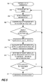
- the process includes receiving motion video, step 202, and detecting objects images in the motion video, step 204.
- the position of the object image 18 is then compared to positions occupied by at least one of the detection lines14, 16, step 206. If a detected object image 18 crosses one of the detection lines 14, 16, then the process continue to step 208. If a detected object image 18 does not cross one of the detection lines 14, 16, then the process returns and receives further motion video and continues to detect object images.
- the system interprets as a crossing of a line.
- One way to implement the system is to have it detect a crossing of the line when a box drawn around the object image touches the line.
- Another is to detect a crossing as soon as a pixel or a couple of pixels of the detected object image touches the line.
- Yet another way is to detect a crossing of the line when a predetermined amount of the object image has crossed the line or when the entire object image has crossed the line and is moving away from it on the other side.
- the lines used in detecting may vary depending on the implementation.
- the area A o of the object image 18 is calculated, step 208.
- the area A o may also be determined in different ways which have been described previously.
- the shortest distance between the detection lines 14, 16 in a detection line pair at the position of the line crossing is calculated, step 210.
- Other schemes for arriving at a distance between the two lines 14, 16, at the location of the object crossing one of the lines may be implemented as discussed earlier.
- the area of the object A o and the distance between the lines at the crossing of one of the lines Ld is then used to determine if the area A o of the object image 18 is within a prescribed range at the distance from the camera indicated by the distance between the two lines 14, 16, at that distance, step 212, e.g. by comparing the line distance squared L d 2 with the object area A o as described previously. If the relationship between the line distance L d and the area A o of the object image 18 crossing the line 14, 16, is indicating that the real world object is of a size that is interesting for the present monitoring scheme then a tripwire event is generated, step 214, and the tripwire event is presented to a user or users on an alarm signalling device or on a display in a monitoring client. If the area A o of the object crossing the line 14, 16, is determined to be of a value that is smaller or larger than the objects of interest then the process returns to step 202 and continues monitoring the tripwires without generating a tripwire event.
- This line crossing detection device 300 includes a video input device 302, an object image detector 304, a processing unit 306, a non-volatile memory 308, a tripwire event generator 310, an output 312 for output of data including the event.
- the line crossing detection device 300 may be a general purpose computer, a networked video encoder arranged to encode analog video do digital video and send the resulting video to clients via a computer network, or a device built for the purpose of detecting line crossings in motion video.
- the video input 302 is a port configured to receive motion video, e.g. analog video or network traffic including digital video.
- the object detector 304 is configured to detect objects in the received motion video.
- the object image detector 304 may be implemented using electronic circuitry, logic gates etc.
- the object image detector 304 may also be implemented by means of program code that is executed in a processing device, which could be a separate processing device or the processing unit 306.
- the function of the object image detector 304 is to identify object images in the received motion video and the skilled person is well aware of a plurality of different possible implementations for achieving such functionality.
- the processing unit 306 may be any type of general purpose processor, e.g. a microprocessor, a CPU, etc., that is enable to execute program code stored in a memory.
- the processing unit 306 is running code relating to the detection of an object image 18 crossing at least one of the lines 14, 16, in the detection line pair 14, 16, relating to calculating the area of an object image, calculating the relation between line distance Ld and object image area Ao, and based on these operations send an instruction for generation of a tripwire event.
- all the functions described in relation to Fig. 5 is performed by means of executing code in a corresponding processing unit.
- the non-volatile memory 308 may store information such as the program code that are to be executed by the processing unit 306. Further, the non-volatile memory 308 may also store data defining detection lines 14, 16, that are to be used in the line crossing detection and the coefficients k, K, used for the same purpose.
- the tripwire event generator 310 is arranged to generate the tripwire event that is to alert a user or an operator of the fact that a detection line 14, 16, has been crossed.
- the output 312 may be a network connection for sending the tripwire event to a client via a network.
- the output 312 may be a display output presenting an interface to the user or operator and in that case the trip wire event generator 310 may generate a graphic overlay and or a sound to be presented.
- a line crossing detection device is implemented within a networked motion video camera 320.
- An example of such an embodiment is showed in Fig. 7 .
- the output device 312 in the networked motion video camera 320 is a device arranged to provide network connection, which also was an alternative for the line crossing detection device 300.
- the video input 302 is replaced by a lens 322, an image sensor 324, and an image processor 326.
- the line detection process may be implemented to detect line crossing for a plurality of lines.
- Fig. 8 an example of this is shown.
- the figure shows two different detection line pairs, 14a, 16a, and 14b and 16b.
- the line detection operation will operate in the same manner as for one line detection pair with the difference that the process would have to check each detection line pair separately, i.e. a testing for if an object image 18 has crossed a line is performed for each detection line pair 14a, 16a, 14b, 16b, individually.
- the above described process which is described for a single detection line pair, is applicable to the multiple detection line pair as well by processing each detecting line pair 14a, 16a, 14b, 16b, in the same way as has been described for the single detection line pair case previously in this description.
- the skilled person appreciates that the number of detection line pairs may be higher than two.
- One thing that limits the number of detection line pairs may be the resolution of the captured motion video and the number or detection line pairs that may be fitted within one scene. Further, the number of detection line pairs may also be restricted by the processing power of the device implementing the detection process.
- the motion video processed for detection of line crossing may be a motion video made from captured infrared radiation, i.e. an infrared motion video.
- the motion video camera includes an infrared image sensor enabled to capture infrared radiation.
Priority Applications (6)
| Application Number | Priority Date | Filing Date | Title |
|---|---|---|---|
| EP15199524.8A EP3179406B1 (de) | 2015-12-11 | 2015-12-11 | Verfahren zur erhöhung der zuverlässigkeit in überwachungssystemen |
| TW105137556A TWI704529B (zh) | 2015-12-11 | 2016-11-17 | 用以偵測在一場景中之一預定第一線處之一物件越過事件之方法及裝置 |
| CN201611089640.XA CN106874829B (zh) | 2015-12-11 | 2016-12-01 | 提高监测系统的可靠性的方法 |
| JP2016236879A JP6325643B2 (ja) | 2015-12-11 | 2016-12-06 | モニタリングシステムにおける信頼性を高めるための方法 |
| KR1020160165973A KR101889051B1 (ko) | 2015-12-11 | 2016-12-07 | 모니터링 시스템들에서 신뢰성을 증가시키는 방법 |
| US15/374,270 US10055847B2 (en) | 2015-12-11 | 2016-12-09 | Method for increasing reliability in monitoring systems |
Applications Claiming Priority (1)
| Application Number | Priority Date | Filing Date | Title |
|---|---|---|---|
| EP15199524.8A EP3179406B1 (de) | 2015-12-11 | 2015-12-11 | Verfahren zur erhöhung der zuverlässigkeit in überwachungssystemen |
Publications (2)
| Publication Number | Publication Date |
|---|---|
| EP3179406A1 true EP3179406A1 (de) | 2017-06-14 |
| EP3179406B1 EP3179406B1 (de) | 2017-11-22 |
Family
ID=55024761
Family Applications (1)
| Application Number | Title | Priority Date | Filing Date |
|---|---|---|---|
| EP15199524.8A Active EP3179406B1 (de) | 2015-12-11 | 2015-12-11 | Verfahren zur erhöhung der zuverlässigkeit in überwachungssystemen |
Country Status (6)
| Country | Link |
|---|---|
| US (1) | US10055847B2 (de) |
| EP (1) | EP3179406B1 (de) |
| JP (1) | JP6325643B2 (de) |
| KR (1) | KR101889051B1 (de) |
| CN (1) | CN106874829B (de) |
| TW (1) | TWI704529B (de) |
Cited By (1)
| Publication number | Priority date | Publication date | Assignee | Title |
|---|---|---|---|---|
| US11445102B2 (en) | 2018-08-31 | 2022-09-13 | Sony Corporation | Information processing device and information processing method |
Families Citing this family (2)
| Publication number | Priority date | Publication date | Assignee | Title |
|---|---|---|---|---|
| US11475640B2 (en) * | 2020-02-28 | 2022-10-18 | Manuel Martinello | Detection-area fencing with polarity and object ingress/egress monitoring |
| US11556098B2 (en) | 2020-02-28 | 2023-01-17 | Ricoh Company, Ltd. | Tracking conditions concerning an area to automatically generate artificial intelligence based responsive actions |
Citations (5)
| Publication number | Priority date | Publication date | Assignee | Title |
|---|---|---|---|---|
| DE102007058959A1 (de) * | 2007-12-07 | 2009-06-10 | Robert Bosch Gmbh | Konfigurationsmodul für ein Überwachungssystem, Überwachungssystem, Verfahren zur Konfiguration des Überwachungssystems sowie Computerprogramm |
| WO2009126151A1 (en) * | 2008-04-09 | 2009-10-15 | Utc Fire & Security Corporation | Video content analysis |
| GB2484668A (en) * | 2010-10-18 | 2012-04-25 | Intelligent Door Solutions Ltd | Motion Sensitive System and Method of Generating a Control Signal |
| EP2607952A1 (de) * | 2011-12-21 | 2013-06-26 | Axis AB | Überwachungskamera und Verfahren zur Überwachung |
| US20150043777A1 (en) * | 2013-08-08 | 2015-02-12 | Huper Laboratories Co., Ltd. | Three dimensional detecting device and method for detecting images thereof |
Family Cites Families (11)
| Publication number | Priority date | Publication date | Assignee | Title |
|---|---|---|---|---|
| US6816184B1 (en) * | 1998-04-30 | 2004-11-09 | Texas Instruments Incorporated | Method and apparatus for mapping a location from a video image to a map |
| TWI277912B (en) * | 2005-01-11 | 2007-04-01 | Huper Lab Co Ltd | Method for calculating a transform coordinate on a second video of an object having an object coordinate on a first video and related operation process and video surveillance system |
| WO2006103744A1 (ja) * | 2005-03-29 | 2006-10-05 | Fujitsu Limited | 映像管理システム |
| TW200806020A (en) * | 2006-07-07 | 2008-01-16 | Wen Wen Hung Tech Corp | Image tracking method |
| CN101123721A (zh) * | 2007-09-30 | 2008-02-13 | 湖北东润科技有限公司 | 一种智能视频监控系统及其监控方法 |
| RU2484531C2 (ru) * | 2009-01-22 | 2013-06-10 | Государственное научное учреждение центральный научно-исследовательский и опытно-конструкторский институт робототехники и технической кибернетики (ЦНИИ РТК) | Устройство обработки видеоинформации системы охранной сигнализации |
| CN103456024B (zh) * | 2012-06-02 | 2016-03-09 | 浙江西谷数字技术有限公司 | 一种运动目标越线判断方法 |
| KR20140056790A (ko) * | 2012-10-31 | 2014-05-12 | 한국전자통신연구원 | 영상 인식 장치 및 그 방법 |
| JP5574551B2 (ja) * | 2012-12-14 | 2014-08-20 | 株式会社日立国際電気 | 画像処理装置および画像処理方法 |
| CN103345840B (zh) * | 2013-05-28 | 2015-09-23 | 南京正保通信网络技术有限公司 | 一种交叉道路口横穿道路事件视频检测方法 |
| JP2015018330A (ja) * | 2013-07-09 | 2015-01-29 | 大日本印刷株式会社 | 移動体の方向別計数システム |
-
2015
- 2015-12-11 EP EP15199524.8A patent/EP3179406B1/de active Active
-
2016
- 2016-11-17 TW TW105137556A patent/TWI704529B/zh active
- 2016-12-01 CN CN201611089640.XA patent/CN106874829B/zh active Active
- 2016-12-06 JP JP2016236879A patent/JP6325643B2/ja active Active
- 2016-12-07 KR KR1020160165973A patent/KR101889051B1/ko active IP Right Grant
- 2016-12-09 US US15/374,270 patent/US10055847B2/en active Active
Patent Citations (5)
| Publication number | Priority date | Publication date | Assignee | Title |
|---|---|---|---|---|
| DE102007058959A1 (de) * | 2007-12-07 | 2009-06-10 | Robert Bosch Gmbh | Konfigurationsmodul für ein Überwachungssystem, Überwachungssystem, Verfahren zur Konfiguration des Überwachungssystems sowie Computerprogramm |
| WO2009126151A1 (en) * | 2008-04-09 | 2009-10-15 | Utc Fire & Security Corporation | Video content analysis |
| GB2484668A (en) * | 2010-10-18 | 2012-04-25 | Intelligent Door Solutions Ltd | Motion Sensitive System and Method of Generating a Control Signal |
| EP2607952A1 (de) * | 2011-12-21 | 2013-06-26 | Axis AB | Überwachungskamera und Verfahren zur Überwachung |
| US20150043777A1 (en) * | 2013-08-08 | 2015-02-12 | Huper Laboratories Co., Ltd. | Three dimensional detecting device and method for detecting images thereof |
Non-Patent Citations (3)
| Title |
|---|
| "Cisco Video Analytics User Guide", 2011, CISCO SYSTEMS INC. |
| HAO LONG ET AL: "Fuzzy judgment algorithm based on security alarm system in the video surveillance", COMPUTER SCIENCE AND NETWORK TECHNOLOGY (ICCSNT), 2012 2ND INTERNATIONAL CONFERENCE ON, IEEE, 29 December 2012 (2012-12-29), pages 1663 - 1666, XP032420152, ISBN: 978-1-4673-2963-7, DOI: 10.1109/ICCSNT.2012.6526240 * |
| YUN ZHAI ET AL: "Virtual Boundary Crossing Detection without Explicit Object Tracking", ADVANCED VIDEO AND SIGNAL BASED SURVEILLANCE, 2009. AVSS '09. SIXTH IEEE INTERNATIONAL CONFERENCE ON, IEEE, PISCATAWAY, NJ, USA, 2 September 2009 (2009-09-02), pages 518 - 522, XP031542375, ISBN: 978-1-4244-4755-8 * |
Cited By (1)
| Publication number | Priority date | Publication date | Assignee | Title |
|---|---|---|---|---|
| US11445102B2 (en) | 2018-08-31 | 2022-09-13 | Sony Corporation | Information processing device and information processing method |
Also Published As
| Publication number | Publication date |
|---|---|
| KR101889051B1 (ko) | 2018-08-20 |
| US20170169560A1 (en) | 2017-06-15 |
| KR20170069937A (ko) | 2017-06-21 |
| CN106874829B (zh) | 2018-10-26 |
| CN106874829A (zh) | 2017-06-20 |
| JP2017188070A (ja) | 2017-10-12 |
| TWI704529B (zh) | 2020-09-11 |
| EP3179406B1 (de) | 2017-11-22 |
| US10055847B2 (en) | 2018-08-21 |
| JP6325643B2 (ja) | 2018-05-16 |
| TW201721583A (zh) | 2017-06-16 |
Similar Documents
| Publication | Publication Date | Title |
|---|---|---|
| CN110794405B (zh) | 一种基于相机和雷达融合的目标检测方法及系统 | |
| US8731241B2 (en) | Activity mapping system | |
| US10438069B2 (en) | Method and apparatus for detecting abnormal situation, and non-transitory computer-readable recording medium | |
| WO2016199244A1 (ja) | 物体認識装置及び物体認識システム | |
| KR101546933B1 (ko) | 화재 감지 장치 | |
| CN109727275B (zh) | 目标检测方法、装置、系统和计算机可读存储介质 | |
| KR101530255B1 (ko) | 객체 자동 추적 장치가 구비된 cctv 시스템 | |
| US10055847B2 (en) | Method for increasing reliability in monitoring systems | |
| CN111179329A (zh) | 三维目标检测方法、装置及电子设备 | |
| CN111724558A (zh) | 一种监控方法、装置及入侵报警系统 | |
| KR101666466B1 (ko) | 단안 카메라를 이용한 해상 객체 거리측정 시스템을 이용한 해상 위험관리 시스템 및 해상 위험 관리방법 | |
| CN112215037B (zh) | 对象追踪方法及装置、电子设备及计算机可读存储介质 | |
| JP6494418B2 (ja) | 画像解析装置、画像解析方法、およびプログラム | |
| CN109886064A (zh) | 确定可驾驶空间的边界的方法 | |
| CN110807758A (zh) | 保温被未覆盖区域检测方法、装置、设备和存储介质 | |
| CN108111802B (zh) | 视频监控方法及装置 | |
| CN112784642A (zh) | 车辆检测方法及装置 | |
| JP2018063675A (ja) | 画像処理装置および制御方法 | |
| JP7079466B2 (ja) | 人属性認識システムおよびプログラム | |
| JP6784254B2 (ja) | 滞留物体検出システム、滞留物体検出方法およびプログラム | |
| CN114255477A (zh) | 一种吸烟行为检测的方法和相关装置 | |
| JP7243372B2 (ja) | 物体追跡装置および物体追跡方法 | |
| JP3957495B2 (ja) | 画像センサ | |
| KR101543096B1 (ko) | 2d와 3d 영상 분석을 이용한 침입 감지 방법 | |
| JP6230877B2 (ja) | 画像処理装置 |
Legal Events
| Date | Code | Title | Description |
|---|---|---|---|
| STAA | Information on the status of an ep patent application or granted ep patent |
Free format text: STATUS: EXAMINATION IS IN PROGRESS |
|
| PUAI | Public reference made under article 153(3) epc to a published international application that has entered the european phase |
Free format text: ORIGINAL CODE: 0009012 |
|
| 17P | Request for examination filed |
Effective date: 20160817 |
|
| AK | Designated contracting states |
Kind code of ref document: A1 Designated state(s): AL AT BE BG CH CY CZ DE DK EE ES FI FR GB GR HR HU IE IS IT LI LT LU LV MC MK MT NL NO PL PT RO RS SE SI SK SM TR |
|
| AX | Request for extension of the european patent |
Extension state: BA ME |
|
| GRAP | Despatch of communication of intention to grant a patent |
Free format text: ORIGINAL CODE: EPIDOSNIGR1 |
|
| STAA | Information on the status of an ep patent application or granted ep patent |
Free format text: STATUS: GRANT OF PATENT IS INTENDED |
|
| RIC1 | Information provided on ipc code assigned before grant |
Ipc: G06T 7/20 20170101ALI20170626BHEP Ipc: G08B 13/196 20060101ALI20170626BHEP Ipc: G06K 9/00 20060101AFI20170626BHEP |
|
| INTG | Intention to grant announced |
Effective date: 20170727 |
|
| GRAS | Grant fee paid |
Free format text: ORIGINAL CODE: EPIDOSNIGR3 |
|
| GRAA | (expected) grant |
Free format text: ORIGINAL CODE: 0009210 |
|
| STAA | Information on the status of an ep patent application or granted ep patent |
Free format text: STATUS: THE PATENT HAS BEEN GRANTED |
|
| AK | Designated contracting states |
Kind code of ref document: B1 Designated state(s): AL AT BE BG CH CY CZ DE DK EE ES FI FR GB GR HR HU IE IS IT LI LT LU LV MC MK MT NL NO PL PT RO RS SE SI SK SM TR |
|
| REG | Reference to a national code |
Ref country code: GB Ref legal event code: FG4D |
|
| REG | Reference to a national code |
Ref country code: FR Ref legal event code: PLFP Year of fee payment: 3 |
|
| REG | Reference to a national code |
Ref country code: CH Ref legal event code: EP |
|
| REG | Reference to a national code |
Ref country code: IE Ref legal event code: FG4D |
|
| REG | Reference to a national code |
Ref country code: AT Ref legal event code: REF Ref document number: 949052 Country of ref document: AT Kind code of ref document: T Effective date: 20171215 |
|
| REG | Reference to a national code |
Ref country code: SE Ref legal event code: TRGR |
|
| REG | Reference to a national code |
Ref country code: DE Ref legal event code: R096 Ref document number: 602015006164 Country of ref document: DE |
|
| REG | Reference to a national code |
Ref country code: NL Ref legal event code: MP Effective date: 20171122 |
|
| REG | Reference to a national code |
Ref country code: LT Ref legal event code: MG4D |
|
| REG | Reference to a national code |
Ref country code: AT Ref legal event code: MK05 Ref document number: 949052 Country of ref document: AT Kind code of ref document: T Effective date: 20171122 |
|
| PG25 | Lapsed in a contracting state [announced via postgrant information from national office to epo] |
Ref country code: LT Free format text: LAPSE BECAUSE OF FAILURE TO SUBMIT A TRANSLATION OF THE DESCRIPTION OR TO PAY THE FEE WITHIN THE PRESCRIBED TIME-LIMIT Effective date: 20171122 Ref country code: NO Free format text: LAPSE BECAUSE OF FAILURE TO SUBMIT A TRANSLATION OF THE DESCRIPTION OR TO PAY THE FEE WITHIN THE PRESCRIBED TIME-LIMIT Effective date: 20180222 Ref country code: ES Free format text: LAPSE BECAUSE OF FAILURE TO SUBMIT A TRANSLATION OF THE DESCRIPTION OR TO PAY THE FEE WITHIN THE PRESCRIBED TIME-LIMIT Effective date: 20171122 Ref country code: NL Free format text: LAPSE BECAUSE OF FAILURE TO SUBMIT A TRANSLATION OF THE DESCRIPTION OR TO PAY THE FEE WITHIN THE PRESCRIBED TIME-LIMIT Effective date: 20171122 Ref country code: FI Free format text: LAPSE BECAUSE OF FAILURE TO SUBMIT A TRANSLATION OF THE DESCRIPTION OR TO PAY THE FEE WITHIN THE PRESCRIBED TIME-LIMIT Effective date: 20171122 |
|
| PG25 | Lapsed in a contracting state [announced via postgrant information from national office to epo] |
Ref country code: AT Free format text: LAPSE BECAUSE OF FAILURE TO SUBMIT A TRANSLATION OF THE DESCRIPTION OR TO PAY THE FEE WITHIN THE PRESCRIBED TIME-LIMIT Effective date: 20171122 Ref country code: GR Free format text: LAPSE BECAUSE OF FAILURE TO SUBMIT A TRANSLATION OF THE DESCRIPTION OR TO PAY THE FEE WITHIN THE PRESCRIBED TIME-LIMIT Effective date: 20180223 Ref country code: HR Free format text: LAPSE BECAUSE OF FAILURE TO SUBMIT A TRANSLATION OF THE DESCRIPTION OR TO PAY THE FEE WITHIN THE PRESCRIBED TIME-LIMIT Effective date: 20171122 Ref country code: RS Free format text: LAPSE BECAUSE OF FAILURE TO SUBMIT A TRANSLATION OF THE DESCRIPTION OR TO PAY THE FEE WITHIN THE PRESCRIBED TIME-LIMIT Effective date: 20171122 Ref country code: LV Free format text: LAPSE BECAUSE OF FAILURE TO SUBMIT A TRANSLATION OF THE DESCRIPTION OR TO PAY THE FEE WITHIN THE PRESCRIBED TIME-LIMIT Effective date: 20171122 Ref country code: BG Free format text: LAPSE BECAUSE OF FAILURE TO SUBMIT A TRANSLATION OF THE DESCRIPTION OR TO PAY THE FEE WITHIN THE PRESCRIBED TIME-LIMIT Effective date: 20180222 |
|
| PG25 | Lapsed in a contracting state [announced via postgrant information from national office to epo] |
Ref country code: CZ Free format text: LAPSE BECAUSE OF FAILURE TO SUBMIT A TRANSLATION OF THE DESCRIPTION OR TO PAY THE FEE WITHIN THE PRESCRIBED TIME-LIMIT Effective date: 20171122 Ref country code: SK Free format text: LAPSE BECAUSE OF FAILURE TO SUBMIT A TRANSLATION OF THE DESCRIPTION OR TO PAY THE FEE WITHIN THE PRESCRIBED TIME-LIMIT Effective date: 20171122 Ref country code: CY Free format text: LAPSE BECAUSE OF FAILURE TO SUBMIT A TRANSLATION OF THE DESCRIPTION OR TO PAY THE FEE WITHIN THE PRESCRIBED TIME-LIMIT Effective date: 20171122 Ref country code: EE Free format text: LAPSE BECAUSE OF FAILURE TO SUBMIT A TRANSLATION OF THE DESCRIPTION OR TO PAY THE FEE WITHIN THE PRESCRIBED TIME-LIMIT Effective date: 20171122 Ref country code: DK Free format text: LAPSE BECAUSE OF FAILURE TO SUBMIT A TRANSLATION OF THE DESCRIPTION OR TO PAY THE FEE WITHIN THE PRESCRIBED TIME-LIMIT Effective date: 20171122 |
|
| REG | Reference to a national code |
Ref country code: DE Ref legal event code: R097 Ref document number: 602015006164 Country of ref document: DE |
|
| PG25 | Lapsed in a contracting state [announced via postgrant information from national office to epo] |
Ref country code: PL Free format text: LAPSE BECAUSE OF FAILURE TO SUBMIT A TRANSLATION OF THE DESCRIPTION OR TO PAY THE FEE WITHIN THE PRESCRIBED TIME-LIMIT Effective date: 20171122 Ref country code: SM Free format text: LAPSE BECAUSE OF FAILURE TO SUBMIT A TRANSLATION OF THE DESCRIPTION OR TO PAY THE FEE WITHIN THE PRESCRIBED TIME-LIMIT Effective date: 20171122 Ref country code: IT Free format text: LAPSE BECAUSE OF FAILURE TO SUBMIT A TRANSLATION OF THE DESCRIPTION OR TO PAY THE FEE WITHIN THE PRESCRIBED TIME-LIMIT Effective date: 20171122 |
|
| REG | Reference to a national code |
Ref country code: IE Ref legal event code: MM4A |
|
| PG25 | Lapsed in a contracting state [announced via postgrant information from national office to epo] |
Ref country code: MT Free format text: LAPSE BECAUSE OF NON-PAYMENT OF DUE FEES Effective date: 20171211 Ref country code: LU Free format text: LAPSE BECAUSE OF NON-PAYMENT OF DUE FEES Effective date: 20171211 |
|
| PLBE | No opposition filed within time limit |
Free format text: ORIGINAL CODE: 0009261 |
|
| STAA | Information on the status of an ep patent application or granted ep patent |
Free format text: STATUS: NO OPPOSITION FILED WITHIN TIME LIMIT |
|
| REG | Reference to a national code |
Ref country code: BE Ref legal event code: MM Effective date: 20171231 |
|
| 26N | No opposition filed |
Effective date: 20180823 |
|
| PG25 | Lapsed in a contracting state [announced via postgrant information from national office to epo] |
Ref country code: IE Free format text: LAPSE BECAUSE OF NON-PAYMENT OF DUE FEES Effective date: 20171211 |
|
| PG25 | Lapsed in a contracting state [announced via postgrant information from national office to epo] |
Ref country code: BE Free format text: LAPSE BECAUSE OF NON-PAYMENT OF DUE FEES Effective date: 20171231 |
|
| PG25 | Lapsed in a contracting state [announced via postgrant information from national office to epo] |
Ref country code: MC Free format text: LAPSE BECAUSE OF FAILURE TO SUBMIT A TRANSLATION OF THE DESCRIPTION OR TO PAY THE FEE WITHIN THE PRESCRIBED TIME-LIMIT Effective date: 20171122 Ref country code: HU Free format text: LAPSE BECAUSE OF FAILURE TO SUBMIT A TRANSLATION OF THE DESCRIPTION OR TO PAY THE FEE WITHIN THE PRESCRIBED TIME-LIMIT; INVALID AB INITIO Effective date: 20151211 |
|
| REG | Reference to a national code |
Ref country code: CH Ref legal event code: PL |
|
| PG25 | Lapsed in a contracting state [announced via postgrant information from national office to epo] |
Ref country code: RO Free format text: LAPSE BECAUSE OF FAILURE TO SUBMIT A TRANSLATION OF THE DESCRIPTION OR TO PAY THE FEE WITHIN THE PRESCRIBED TIME-LIMIT Effective date: 20171122 |
|
| PG25 | Lapsed in a contracting state [announced via postgrant information from national office to epo] |
Ref country code: SI Free format text: LAPSE BECAUSE OF FAILURE TO SUBMIT A TRANSLATION OF THE DESCRIPTION OR TO PAY THE FEE WITHIN THE PRESCRIBED TIME-LIMIT Effective date: 20171122 |
|
| PG25 | Lapsed in a contracting state [announced via postgrant information from national office to epo] |
Ref country code: MK Free format text: LAPSE BECAUSE OF FAILURE TO SUBMIT A TRANSLATION OF THE DESCRIPTION OR TO PAY THE FEE WITHIN THE PRESCRIBED TIME-LIMIT Effective date: 20171122 |
|
| PG25 | Lapsed in a contracting state [announced via postgrant information from national office to epo] |
Ref country code: LI Free format text: LAPSE BECAUSE OF NON-PAYMENT OF DUE FEES Effective date: 20181231 Ref country code: CH Free format text: LAPSE BECAUSE OF NON-PAYMENT OF DUE FEES Effective date: 20181231 |
|
| PG25 | Lapsed in a contracting state [announced via postgrant information from national office to epo] |
Ref country code: TR Free format text: LAPSE BECAUSE OF FAILURE TO SUBMIT A TRANSLATION OF THE DESCRIPTION OR TO PAY THE FEE WITHIN THE PRESCRIBED TIME-LIMIT Effective date: 20171122 |
|
| PG25 | Lapsed in a contracting state [announced via postgrant information from national office to epo] |
Ref country code: PT Free format text: LAPSE BECAUSE OF FAILURE TO SUBMIT A TRANSLATION OF THE DESCRIPTION OR TO PAY THE FEE WITHIN THE PRESCRIBED TIME-LIMIT Effective date: 20171122 |
|
| PG25 | Lapsed in a contracting state [announced via postgrant information from national office to epo] |
Ref country code: AL Free format text: LAPSE BECAUSE OF FAILURE TO SUBMIT A TRANSLATION OF THE DESCRIPTION OR TO PAY THE FEE WITHIN THE PRESCRIBED TIME-LIMIT Effective date: 20171122 Ref country code: IS Free format text: LAPSE BECAUSE OF FAILURE TO SUBMIT A TRANSLATION OF THE DESCRIPTION OR TO PAY THE FEE WITHIN THE PRESCRIBED TIME-LIMIT Effective date: 20180322 |
|
| REG | Reference to a national code |
Ref country code: DE Ref legal event code: R079 Ref document number: 602015006164 Country of ref document: DE Free format text: PREVIOUS MAIN CLASS: G06K0009000000 Ipc: G06V0010000000 |
|
| P01 | Opt-out of the competence of the unified patent court (upc) registered |
Effective date: 20230505 |
|
| PGFP | Annual fee paid to national office [announced via postgrant information from national office to epo] |
Ref country code: GB Payment date: 20231121 Year of fee payment: 9 |
|
| PGFP | Annual fee paid to national office [announced via postgrant information from national office to epo] |
Ref country code: SE Payment date: 20231121 Year of fee payment: 9 Ref country code: FR Payment date: 20231122 Year of fee payment: 9 Ref country code: DE Payment date: 20231121 Year of fee payment: 9 |