EP3179406A1 - Method for increasing reliability in monitoring systems - Google Patents
Method for increasing reliability in monitoring systems Download PDFInfo
- Publication number
- EP3179406A1 EP3179406A1 EP15199524.8A EP15199524A EP3179406A1 EP 3179406 A1 EP3179406 A1 EP 3179406A1 EP 15199524 A EP15199524 A EP 15199524A EP 3179406 A1 EP3179406 A1 EP 3179406A1
- Authority
- EP
- European Patent Office
- Prior art keywords
- line
- predetermined
- scene
- image
- size
- Prior art date
- Legal status (The legal status is an assumption and is not a legal conclusion. Google has not performed a legal analysis and makes no representation as to the accuracy of the status listed.)
- Granted
Links
- 238000000034 method Methods 0.000 title claims abstract description 52
- 238000012544 monitoring process Methods 0.000 title description 4
- 238000001514 detection method Methods 0.000 claims description 77
- 230000008569 process Effects 0.000 claims description 22
- 238000012545 processing Methods 0.000 description 10
- 230000008901 benefit Effects 0.000 description 5
- 230000006870 function Effects 0.000 description 3
- 241001465754 Metazoa Species 0.000 description 2
- 238000010586 diagram Methods 0.000 description 2
- 230000005855 radiation Effects 0.000 description 2
- 241000208199 Buxus sempervirens Species 0.000 description 1
- 241000282472 Canis lupus familiaris Species 0.000 description 1
- 244000025254 Cannabis sativa Species 0.000 description 1
- 241000282412 Homo Species 0.000 description 1
- 241000283973 Oryctolagus cuniculus Species 0.000 description 1
- 241000283080 Proboscidea <mammal> Species 0.000 description 1
- 241000555745 Sciuridae Species 0.000 description 1
- 238000004458 analytical method Methods 0.000 description 1
- 230000006399 behavior Effects 0.000 description 1
- 230000008859 change Effects 0.000 description 1
- 238000010191 image analysis Methods 0.000 description 1
- 238000012986 modification Methods 0.000 description 1
- 230000004048 modification Effects 0.000 description 1
- 230000003287 optical effect Effects 0.000 description 1
- 230000011664 signaling Effects 0.000 description 1
- 238000012360 testing method Methods 0.000 description 1
- 230000001960 triggered effect Effects 0.000 description 1
Images


Classifications
-
- G—PHYSICS
- G06—COMPUTING; CALCULATING OR COUNTING
- G06T—IMAGE DATA PROCESSING OR GENERATION, IN GENERAL
- G06T7/00—Image analysis
- G06T7/70—Determining position or orientation of objects or cameras
-
- G—PHYSICS
- G06—COMPUTING; CALCULATING OR COUNTING
- G06V—IMAGE OR VIDEO RECOGNITION OR UNDERSTANDING
- G06V40/00—Recognition of biometric, human-related or animal-related patterns in image or video data
- G06V40/10—Human or animal bodies, e.g. vehicle occupants or pedestrians; Body parts, e.g. hands
- G06V40/103—Static body considered as a whole, e.g. static pedestrian or occupant recognition
-
- G—PHYSICS
- G08—SIGNALLING
- G08B—SIGNALLING OR CALLING SYSTEMS; ORDER TELEGRAPHS; ALARM SYSTEMS
- G08B13/00—Burglar, theft or intruder alarms
- G08B13/18—Actuation by interference with heat, light, or radiation of shorter wavelength; Actuation by intruding sources of heat, light, or radiation of shorter wavelength
- G08B13/189—Actuation by interference with heat, light, or radiation of shorter wavelength; Actuation by intruding sources of heat, light, or radiation of shorter wavelength using passive radiation detection systems
- G08B13/194—Actuation by interference with heat, light, or radiation of shorter wavelength; Actuation by intruding sources of heat, light, or radiation of shorter wavelength using passive radiation detection systems using image scanning and comparing systems
- G08B13/196—Actuation by interference with heat, light, or radiation of shorter wavelength; Actuation by intruding sources of heat, light, or radiation of shorter wavelength using passive radiation detection systems using image scanning and comparing systems using television cameras
-
- G—PHYSICS
- G06—COMPUTING; CALCULATING OR COUNTING
- G06T—IMAGE DATA PROCESSING OR GENERATION, IN GENERAL
- G06T7/00—Image analysis
- G06T7/10—Segmentation; Edge detection
- G06T7/11—Region-based segmentation
-
- G—PHYSICS
- G06—COMPUTING; CALCULATING OR COUNTING
- G06T—IMAGE DATA PROCESSING OR GENERATION, IN GENERAL
- G06T7/00—Image analysis
- G06T7/20—Analysis of motion
-
- G—PHYSICS
- G06—COMPUTING; CALCULATING OR COUNTING
- G06T—IMAGE DATA PROCESSING OR GENERATION, IN GENERAL
- G06T7/00—Image analysis
- G06T7/60—Analysis of geometric attributes
-
- G—PHYSICS
- G06—COMPUTING; CALCULATING OR COUNTING
- G06V—IMAGE OR VIDEO RECOGNITION OR UNDERSTANDING
- G06V20/00—Scenes; Scene-specific elements
- G06V20/40—Scenes; Scene-specific elements in video content
-
- G—PHYSICS
- G06—COMPUTING; CALCULATING OR COUNTING
- G06V—IMAGE OR VIDEO RECOGNITION OR UNDERSTANDING
- G06V20/00—Scenes; Scene-specific elements
- G06V20/50—Context or environment of the image
- G06V20/52—Surveillance or monitoring of activities, e.g. for recognising suspicious objects
-
- H—ELECTRICITY
- H04—ELECTRIC COMMUNICATION TECHNIQUE
- H04N—PICTORIAL COMMUNICATION, e.g. TELEVISION
- H04N7/00—Television systems
- H04N7/18—Closed-circuit television [CCTV] systems, i.e. systems in which the video signal is not broadcast
-
- H—ELECTRICITY
- H04—ELECTRIC COMMUNICATION TECHNIQUE
- H04N—PICTORIAL COMMUNICATION, e.g. TELEVISION
- H04N7/00—Television systems
- H04N7/18—Closed-circuit television [CCTV] systems, i.e. systems in which the video signal is not broadcast
- H04N7/188—Capturing isolated or intermittent images triggered by the occurrence of a predetermined event, e.g. an object reaching a predetermined position
Abstract
Description
- The present invention relates to analysis of captured motion video and more particularly to a method for detecting, in a motion video, objects crossing a predetermined line.
- One common task in surveillance is to determine if someone or something crosses a predetermined boundary or line, e.g. a fence. This type of surveillance is a tedious task if performed manually and therefore various automatic systems has been suggested over the years. Different types of tripwires have been used, from real physical wires to beams of light. In later years the tripwire have entered the logic realm as well. In this incarnation it is implemented in software analysing motion video captured by a camera. Such logic tripwires is generally defining one or a plurality of lines in the captured scene and then the motion video is analysed for identifying objects moving in the video and if an identified object breaks a defined line an event is generated. The event may result in an alarm, an indication on an operator interface, an entry in a log, etc.
- In order to have the system generate useful alarms and to avoid generation of false positives the systems generally is configured to only generate an event in the cases when the object crossing the logic line in the scene is of a type that is interesting. In some applications the interesting type of objects is humans, in other applications it is elephants, in yet other applications it is dogs. The interesting types of objects may even be products in a process, e.g. objects transported on a conveyer belt that are not to bounce of the conveyer belt. One problem with a simple tripwire implementation which may result in false positives is that the event is generated as soon as a detected object crosses the line independent of whether the detected object is a mouse, a human, or a truck. This problem has been solved in some known implementations by making the system generate an event only when the detected object is of a particular size or within a particular range of sizes.
- In "Cisco Video Analytics User Guide", 2011, Text Part Number: OL-24428-01, from Cisco Systems Inc., 170 West Tasman Drive, San Jose, CA 95134-1706, USA, a system implementing a minimum size filter and a maximum size filter for eliminating objects that are smaller than a specified size and eliminating objects that are larger than a specified size from the general video analytics process. The maximum filter is set in a snapshot of the scene. Two boxes, one for the foreground and one for the background, is presented in the snapshot of the scene. The user is then to change the size of each of the boxes in order to indicate the maximum size of objects in the foreground and in the background, respectively. The same procedure is then performed for the minimum size filter, i.e. boxes are presented and the sizes of the boxes are adjusted. The document further describes two examples in which the maximum size filter and the minimum size filter, respectively, may be used. For example, a shadow from a tree or a tree branch may be mis-classified as a person. This may results in false alarms if the wind blows in the tree and its shadow crosses a video tripwire. In such a case the maximum object filter may be defined to provide the system with enough information to disregard excessively large objects that cross the video tripwire. In another example a small animal such as a squirrel may be mis-classified and trigger a false alarm when crossing a video tripwire. This situation may then be solved using a minimum object size filter which makes the system disregard small objects that cross the video tripwire.
- Hence, the above implementation solves the problem of false positives resulting from objects having a size distinguishable from the size of the objects that are to be detected. However, the act of setting the filters are quite cumbersome and adjusting the settings for the filters are not easier.
- One object of the present invention is to provide improved detection of objects crossing predetermined lines in a scene captured by means of a motion video camera. An additional object is to decrease the number of false positives resulting from objects having a size distinguishable from the size of the objects that are to be detected.
- According to a first aspect, these and other objects are achieved, in full or at least in part by a method for detecting an object crossing event at a predetermined first line in a scene captured by means of a motion video camera. The method comprises determining from images of the scene captured by the motion video camera if an object image crosses the predetermined first line, calculating a size value relating to the size of the object image crossing the predetermined first line, setting a line distance value to a value calculated from the distance between a contact point of the object with the predetermined first line and a nearby point on a predetermined second line, and generating an object crossing event signal if a relation between the calculated size value and the line distance is within a predetermined range. The advantage of relating the size of the object image to a reference in the scene at the position of the object image is that it is possible to determine a relation between the size of the object image in the captured scene and the real size of the corresponding real world object. Thereby, it is possible to determine if the real world size of the object is within a specific size range independently of where along the detection line the object image size is calculated and, thus, making it possible to reduce the risk of generating false positives from objects that are of a size that are not of interest. This is possible due to the possibility to provide a reference that scales with the depth of the captured image, i.e. the reference is smaller at greater distance from the camera, which corresponds to the behaviour of an object positioned at different distances from the camera. Moreover, by introducing two lines and making the distance between the two lines at the position of the object crossing the line being the reference makes the process of setting up rules for line crossing more simple and the results less prone to false positives.
- The size of the object may be related to the size of the area occupied by the object in the captured image. Further, the size of the area related to the size of the object may be calculated from the number of image elements the object occupies in the captured image.
- In some embodiments the determining if an object crosses the predetermined first line may include detecting in images captured of the scene if an image element representing the object is positioned on an image element included in the predetermined first line. According to some embodiments the predetermined first line and the predetermined second line are virtual lines, wherein each line is defined by at least two coordinates representing positions within the scene. The first and second predetermined lines may be defined in the scene so that they are closer to each other at image elements in the scene representing positions further away from the camera. By having the lines be defined in this fashion it will be easy for the user setting up the event rules relating to crossing a line in that various reference values at different distances from the camera may easily approximated by the person by simply making the lines approximate the perspective properties of the scene. For many persons it is easy and natural to draw two lines in perspective in the captured scene of a camera emulating the perspective view of two parallel lines in the real world. In general, a typical scene would contain several object references that could be used to verify the accuracy of the distance between the two lines. Admittedly, these object references are rarely a pair of railroad tracks, but trees, poles, portions of a fence, a window, grass etc. all readily processed by the complex image analysis available in the human mind. This makes the present method surprisingly robust.
- The determining of a line distance may include calculating a position along the predetermined second line having the shortest distance to the contact point of the object with the predetermined first line. The advantage of accessing a reference value in this way is that it is an easy method for getting a reference value from the more or less continuously adapting reference value introduced by the two lines.
- Moreover, the predetermined first line and the predetermined second line may be a detection line pair and a plurality of detection line pairs may be defined for a scene. In this way it is possible to define events for crossing of more than one line or limit in the scene. It will also facilitate the generation of cross line events for complex lines in the scene.
- In some embodiments the object crossing event signal is generated when the relation between calculated size of the object and the line distance squared is within the predetermined range. Moreover, the object crossing event signal may be generated as soon as the relation

- According to another aspect a system for detecting objects crossing predetermined lines in a captured scene may be configured to perform the various methods presented above. The advantages for features in such a system will coincide with the advantages for the corresponding feature in the method.
- A further scope of applicability of the present invention will become apparent from the detailed description given below. However, it should be understood that the detailed description and specific examples, while indicating preferred embodiments of the invention, are given by way of illustration only, since various changes and modifications within the scope of the invention will become apparent to those skilled in the art from this detailed description. Hence, it is to be understood that this invention is not limited to the particular component parts of the device described or steps of the methods described as such device and method may vary. It is also to be understood that the terminology used herein is for purpose of describing particular embodiments only, and is not intended to be limiting. It must be noted that, as used in the specification and the appended claim, the articles "a," "an," "the," and "said" are intended to mean that there are one or more of the elements unless the context clearly dictates otherwise. Thus, for example, reference to "a sensor" or "the sensor" may include several sensors, and the like. Furthermore, the word "comprising" does not exclude other elements or steps.
- Other features and advantages of the present invention will become apparent from the following detailed description of a presently preferred embodiment, with reference to the accompanying drawings, in which:
-
Fig. 1 is a schematic image representing a scene including a natural access limit, i.e. the fence, in which image an overlay of a detection line pair and an object detection box has been inserted; -
Fig. 2 is a schematic image presenting the detection line pair and the object detection box ofFig. 1 and illustrates the parameters operated on according to a methods according to some embodiments of the invention; -
Fig. 3 is a schematic image presenting the detection line pair ofFig. 1 and two examples of objects having sizes larger than and smaller than an event generating size; -
Fig. 4 is a flowchart of a process for setting up detection lines in a scene; -
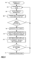
Fig. 5 is a flowchart of a method for detecting an object crossing event at a predetermined first line in a scene captured by means of a motion video camera; -
Fig. 6 is a schematic block diagram over a line crossing detection device according to some embodiments of the invention; -
Fig. 7 is a schematic block diagram over a line crossing detection device in a motion video camera according to some embodiments of the invention; and -
Fig. 8 is a schematic image showing a plurality of detection line pairs. - Further, in the figures like reference characters designate like or corresponding parts throughout the several figures.
- As described above is the present invention related to perimeter surveillance and/or surveillance in areas where a line or a plurality of connected lines defines a boundary or a limit that is prohibited to pass by a person, an animal, or any other object as discussed above. In this text the detection of an object crossing a predetermined line or limit may be referred to tripwire, tripwire detection, perimeter crossing detection, line crossing detection. These terms are all representing the same function of detecting or reacting to the event of an object crossing a predetermined line in the scene.
- Now referring to
Fig. 1 , in which an example of a surveyed scene 10 as captured by a motion video camera is shown. In the scene there is a physical perimeter in the form of afence 12. In the present example we assume that thefence 12 is a perimeter not to be passed by persons. In order to facilitate detection of a person passing the perimeter thephysical perimeter 12 is represented by a pair oflogical lines logical lines - The system performing the detection also includes an object detection functionality for detecting objects in particular moving objects in the scene. Further, the system is arranged to determine or approximate an area Ao of an
object image 18, wherein theobject image 18 is the representation of the real world object as captured by a motion video camera. The object detection and the determination or approximation of the object image area Ao may be performed using any known process, algorithm or numerical method. The area may for instance be calculated by approximating arectangle 20 or a polygon to the detectedobject image 18 and then count the number of image elements inside therectangle 20 or the polygon. An image element may be an image block or it may be a pixel. - In embodiments of the invention a detected object is determined to be an object of interest based on the determined area of the detected
object image 18 and the distance between the twolines object image 18 is detected to cross the line. The relation between the area of anobject image 18 and the distance between the twolines lines lines perimeter 12 is found. Hence, the distance between the twolines object image 18 is within a predetermined range. - In
Fig. 2 the parameters considered in determining a tripwire event according to some embodiments are showed. As mentioned previously the distance Ld between thelines object image 18 is crossing one of thelines lines object image 18 detected as crossing theline 14 is determined. This area Ao may be determined by generating a logical box surrounding the object and then calculate the number of pixels in the box. Another alternative is to calculate the area based on the pixels occupied by the detectedobject image 18. The skilled person is well aware of plenty of methods for calculating the area of a specific area in a digital image. In order to determine if theobject image 18 crossing should generate a tripwire event a relation between the distance Ld and the area Ao of the object image is observed. This observation is to be implemented in order to avoid generating a tripwire event for objects evidently not of interest, e.g. a rabbit crossing theperimeter 12, a shadow from a cloud crossing theperimeter 12, etc.Fig. 3 is illustrating areas representing a very small object Ao1 and a very large object Ao2 which both should be outside the range of object sizes that are to generate a tripwire event. Moreover, as seen in this figure the twoobject images 30, 32, are related to different distances between thelines object image 30 having the area Ao1 is related to Ld1 which is a distance between thelines object image 30 is crossing one of the lines and the object image 32 having the area Ao2 is related to Ld2 which is a distance between thelines lines - In some embodiments the relation between the distance Ld between the
lines object image 18 crossing aline object image 18 may be determined by calculating a lower detection limit for the area of theobject image 18 based on the line distance Ld at the position of the object image crossing theline 
- The higher detection limit may be calculated as the line distance Ld squared times a higher detection limit coefficient K:

- Accordingly, the size of an area of a detected object that will trigger a tripwire event may be expressed as follows:

- The value of the lower limit coefficient k and the value of the higher limit coefficient K is, according to some embodiments, pre-set and adjustable. The values of these coefficients may vary depending on the focal length of the lenses used in the camera. They may also vary on zoom levels, if applicable to the optical system of the camera. However, if the
lines - Moreover, the tripwire detection in a setup as described in connection with
Figs 1-3 may be configured to generate the tripwire event when any one of thelines object image 18 having a size within the defined range. However, alternatively only one of thelines lines detection lines detection lines second detection line object image 18 is overlaid on thedetection line - Now, referring to the flowchart in
Fig. 4 , showing a method for the user to set the tripwire detection lines,process 100, according to some embodiments of the invention. First a digital image of the scene for which the tripwire detection is to be set up,step 102, is displayed for the operator setting the detection lines. The digital image may be a still image of the scene, it may be a recorded motion video, or it may be a live motion video stream. Then the user starts by defining thefirst detection line 14 by indicating a first point and a second point in the scene,step 104. The line is then defined as a line between these two points. Then the user defines thesecond detection line 16 by indicating a third point and a fourth point in the scene,step 106. The twolines step 108. When thelines - In the flowchart of
Fig. 5 the process for tripwire event generation, 200, is presented. The process includes receiving motion video,step 202, and detecting objects images in the motion video,step 204. The position of theobject image 18 is then compared to positions occupied by at least one of the detection lines14, 16,step 206. If a detectedobject image 18 crosses one of thedetection lines object image 18 does not cross one of thedetection lines - There are various ways to define what criteria the system is to interpret as a crossing of a line. One way to implement the system is to have it detect a crossing of the line when a box drawn around the object image touches the line. Another is to detect a crossing as soon as a pixel or a couple of pixels of the detected object image touches the line. Yet another way is to detect a crossing of the line when a predetermined amount of the object image has crossed the line or when the entire object image has crossed the line and is moving away from it on the other side. Moreover, as mentioned above, the lines used in detecting may vary depending on the implementation.
- When, an
object image 18 is detected as crossing theline object image 18 is calculated,step 208. The area Ao may also be determined in different ways which have been described previously. Then, in order to decide whether the object detection relates to a relevant object, the shortest distance between thedetection lines step 210. Other schemes for arriving at a distance between the twolines object image 18 is within a prescribed range at the distance from the camera indicated by the distance between the twolines object image 18 crossing theline step 214, and the tripwire event is presented to a user or users on an alarm signalling device or on a display in a monitoring client. If the area Ao of the object crossing theline - Now referring to
Fig. 6 , an example of a linecrossing detection device 300 according to some embodiments of the invention. This line crossing detection device includes avideo input device 302, anobject image detector 304, aprocessing unit 306, anon-volatile memory 308, atripwire event generator 310, anoutput 312 for output of data including the event. The linecrossing detection device 300 may be a general purpose computer, a networked video encoder arranged to encode analog video do digital video and send the resulting video to clients via a computer network, or a device built for the purpose of detecting line crossings in motion video. Thevideo input 302 is a port configured to receive motion video, e.g. analog video or network traffic including digital video. Theobject detector 304 is configured to detect objects in the received motion video. - The
object image detector 304 may be implemented using electronic circuitry, logic gates etc. Theobject image detector 304 may also be implemented by means of program code that is executed in a processing device, which could be a separate processing device or theprocessing unit 306. The function of theobject image detector 304 is to identify object images in the received motion video and the skilled person is well aware of a plurality of different possible implementations for achieving such functionality. - The
processing unit 306 may be any type of general purpose processor, e.g. a microprocessor, a CPU, etc., that is enable to execute program code stored in a memory. In the example linecrossing detection device 300 theprocessing unit 306 is running code relating to the detection of anobject image 18 crossing at least one of thelines detection line pair Fig. 5 is performed by means of executing code in a corresponding processing unit. Thenon-volatile memory 308 may store information such as the program code that are to be executed by theprocessing unit 306. Further, thenon-volatile memory 308 may also store data definingdetection lines - The
tripwire event generator 310 is arranged to generate the tripwire event that is to alert a user or an operator of the fact that adetection line output 312 may be a network connection for sending the tripwire event to a client via a network. Alternatively, theoutput 312 may be a display output presenting an interface to the user or operator and in that case the tripwire event generator 310 may generate a graphic overlay and or a sound to be presented. - In other embodiments a line crossing detection device is implemented within a networked
motion video camera 320. An example of such an embodiment is showed inFig. 7 . Features inFig. 7 having the same reference number as a feature fromFig. 6 are to be understood as being described in connection withFig. 6 and will thus not be described in the description ofFig. 7 . The main difference in features are that theoutput device 312 in the networkedmotion video camera 320 is a device arranged to provide network connection, which also was an alternative for the linecrossing detection device 300. Moreover, thevideo input 302 is replaced by alens 322, animage sensor 324, and animage processor 326. These features are all well known to a person skilled in the art and will therefore not be described in more detail herein. - According to some embodiments of the invention the line detection process may be implemented to detect line crossing for a plurality of lines. In
Fig. 8 an example of this is shown. The figure shows two different detection line pairs, 14a, 16a, and 14b and 16b. The line detection operation will operate in the same manner as for one line detection pair with the difference that the process would have to check each detection line pair separately, i.e. a testing for if anobject image 18 has crossed a line is performed for eachdetection line pair line pair - According to some embodiments the motion video processed for detection of line crossing may be a motion video made from captured infrared radiation, i.e. an infrared motion video. In case of the process being implemented in a motion video camera the motion video camera includes an infrared image sensor enabled to capture infrared radiation.
Claims (11)
- Method for detecting an object crossing event at a predetermined first line (14; 16) in a scene captured by means of a motion video camera, the method comprising:determining from images of the scene captured by the motion video camera if an object image (18) crosses the predetermined first line (14; 16),calculating a size (Ao) value relating to the size of the object image (18) crossing the predetermined first line (14; 16),setting a line distance (Ld) value to a value calculated from the distance between a contact point of the object with the predetermined first line (14;16) and a nearby point on a predetermined second line (16; 14), andgenerating an object crossing event signal if a relation between the calculated size value (Ao) and the line distance (Ld) is within a predetermined range.
- Method according to claim 1, wherein the size value (Ao) relating to the size of the object image (18) is related to the size of the area (Ao) occupied by the object in the captured image.
- Method according to claim 2, wherein the size of the area (Ao) related to the size of the object image (18) is calculated from the number of image elements the object image (18) occupies in the captured image.
- Method according to any one of claims 1-3, wherein the determining if an object crosses the predetermined first line (14; 16) includes detecting in images captured of the scene if image element representing the object is positioned on an image element included in the predetermined first line (14; 16).
- Method according to any one of claims 1-4, wherein the predetermined first line (14; 16) and the predetermined second line (16; 14) are virtual lines, wherein each line (14; 16) is defined by at least two coordinates representing positions within the scene.
- Method according to any one of claims 1-5, wherein the first and second predetermined lines (14; 16) are defined in the scene so that they are closer to each other at image elements in the scene representing positions further away from the motion video camera.
- Method according to any one of claims 1-6, wherein the determining a line distance (Ld) includes calculating a position along the predetermined second line (16; 14) having the shortest distance to the contact point of the object image (18) with the predetermined first line (14; 16).
- Method according to any one of claims 1-7, wherein the predetermined first line (14; 16) and the predetermined second line (16; 14) is a detection line pair and a plurality of detection line pairs (14a; 16a; 14b; 16b) may be defined for a scene.
- Method according to any one of claims 1-8, wherein the object crossing event signal is generated when the relation between calculated size value (Ao) and the line distance (Ld) squared is within the predetermined range.
- Method according to any one of claims 1-9, wherein the object crossing event signal is generated as soon as the relation

- System for detecting objects crossing predetermined lines in a captured scene, said system being configured to perform the process of any one of claims 1-10.
Priority Applications (6)
| Application Number | Priority Date | Filing Date | Title |
|---|---|---|---|
| EP15199524.8A EP3179406B1 (en) | 2015-12-11 | 2015-12-11 | Method for increasing reliability in monitoring systems |
| TW105137556A TWI704529B (en) | 2015-12-11 | 2016-11-17 | Method and device for detecting an object crossing event at a predetermined first line in a scene |
| CN201611089640.XA CN106874829B (en) | 2015-12-11 | 2016-12-01 | The method for improving the reliability of monitoring system |
| JP2016236879A JP6325643B2 (en) | 2015-12-11 | 2016-12-06 | Methods for increasing reliability in monitoring systems |
| KR1020160165973A KR101889051B1 (en) | 2015-12-11 | 2016-12-07 | Method for increasing reliability in monitoring systems |
| US15/374,270 US10055847B2 (en) | 2015-12-11 | 2016-12-09 | Method for increasing reliability in monitoring systems |
Applications Claiming Priority (1)
| Application Number | Priority Date | Filing Date | Title |
|---|---|---|---|
| EP15199524.8A EP3179406B1 (en) | 2015-12-11 | 2015-12-11 | Method for increasing reliability in monitoring systems |
Publications (2)
| Publication Number | Publication Date |
|---|---|
| EP3179406A1 true EP3179406A1 (en) | 2017-06-14 |
| EP3179406B1 EP3179406B1 (en) | 2017-11-22 |
Family
ID=55024761
Family Applications (1)
| Application Number | Title | Priority Date | Filing Date |
|---|---|---|---|
| EP15199524.8A Active EP3179406B1 (en) | 2015-12-11 | 2015-12-11 | Method for increasing reliability in monitoring systems |
Country Status (6)
| Country | Link |
|---|---|
| US (1) | US10055847B2 (en) |
| EP (1) | EP3179406B1 (en) |
| JP (1) | JP6325643B2 (en) |
| KR (1) | KR101889051B1 (en) |
| CN (1) | CN106874829B (en) |
| TW (1) | TWI704529B (en) |
Cited By (1)
| Publication number | Priority date | Publication date | Assignee | Title |
|---|---|---|---|---|
| US11445102B2 (en) | 2018-08-31 | 2022-09-13 | Sony Corporation | Information processing device and information processing method |
Families Citing this family (2)
| Publication number | Priority date | Publication date | Assignee | Title |
|---|---|---|---|---|
| US11556098B2 (en) | 2020-02-28 | 2023-01-17 | Ricoh Company, Ltd. | Tracking conditions concerning an area to automatically generate artificial intelligence based responsive actions |
| US11475640B2 (en) * | 2020-02-28 | 2022-10-18 | Manuel Martinello | Detection-area fencing with polarity and object ingress/egress monitoring |
Citations (5)
| Publication number | Priority date | Publication date | Assignee | Title |
|---|---|---|---|---|
| DE102007058959A1 (en) * | 2007-12-07 | 2009-06-10 | Robert Bosch Gmbh | Configuration module for a monitoring system, monitoring system, method for configuring the monitoring system and computer program |
| WO2009126151A1 (en) * | 2008-04-09 | 2009-10-15 | Utc Fire & Security Corporation | Video content analysis |
| GB2484668A (en) * | 2010-10-18 | 2012-04-25 | Intelligent Door Solutions Ltd | Motion Sensitive System and Method of Generating a Control Signal |
| EP2607952A1 (en) * | 2011-12-21 | 2013-06-26 | Axis AB | Monitoring camera and method for monitoring |
| US20150043777A1 (en) * | 2013-08-08 | 2015-02-12 | Huper Laboratories Co., Ltd. | Three dimensional detecting device and method for detecting images thereof |
Family Cites Families (11)
| Publication number | Priority date | Publication date | Assignee | Title |
|---|---|---|---|---|
| US6816184B1 (en) * | 1998-04-30 | 2004-11-09 | Texas Instruments Incorporated | Method and apparatus for mapping a location from a video image to a map |
| TWI277912B (en) * | 2005-01-11 | 2007-04-01 | Huper Lab Co Ltd | Method for calculating a transform coordinate on a second video of an object having an object coordinate on a first video and related operation process and video surveillance system |
| JP4601666B2 (en) * | 2005-03-29 | 2010-12-22 | 富士通株式会社 | Video search device |
| TW200806020A (en) * | 2006-07-07 | 2008-01-16 | Wen Wen Hung Tech Corp | Image tracking method |
| CN101123721A (en) * | 2007-09-30 | 2008-02-13 | 湖北东润科技有限公司 | An intelligent video monitoring system and its monitoring method |
| RU2484531C2 (en) * | 2009-01-22 | 2013-06-10 | Государственное научное учреждение центральный научно-исследовательский и опытно-конструкторский институт робототехники и технической кибернетики (ЦНИИ РТК) | Apparatus for processing video information of security alarm system |
| CN103456024B (en) * | 2012-06-02 | 2016-03-09 | 浙江西谷数字技术有限公司 | A kind of moving target gets over line determination methods |
| KR20140056790A (en) * | 2012-10-31 | 2014-05-12 | 한국전자통신연구원 | Apparatus for image recognition and method thereof |
| JP5574551B2 (en) * | 2012-12-14 | 2014-08-20 | 株式会社日立国際電気 | Image processing apparatus and image processing method |
| CN103345840B (en) * | 2013-05-28 | 2015-09-23 | 南京正保通信网络技术有限公司 | Road incidents video detecting method is crossed at a kind of cross channel crossing |
| JP2015018330A (en) * | 2013-07-09 | 2015-01-29 | 大日本印刷株式会社 | System for counting moving objects by direction |
-
2015
- 2015-12-11 EP EP15199524.8A patent/EP3179406B1/en active Active
-
2016
- 2016-11-17 TW TW105137556A patent/TWI704529B/en active
- 2016-12-01 CN CN201611089640.XA patent/CN106874829B/en active Active
- 2016-12-06 JP JP2016236879A patent/JP6325643B2/en active Active
- 2016-12-07 KR KR1020160165973A patent/KR101889051B1/en active IP Right Grant
- 2016-12-09 US US15/374,270 patent/US10055847B2/en active Active
Patent Citations (5)
| Publication number | Priority date | Publication date | Assignee | Title |
|---|---|---|---|---|
| DE102007058959A1 (en) * | 2007-12-07 | 2009-06-10 | Robert Bosch Gmbh | Configuration module for a monitoring system, monitoring system, method for configuring the monitoring system and computer program |
| WO2009126151A1 (en) * | 2008-04-09 | 2009-10-15 | Utc Fire & Security Corporation | Video content analysis |
| GB2484668A (en) * | 2010-10-18 | 2012-04-25 | Intelligent Door Solutions Ltd | Motion Sensitive System and Method of Generating a Control Signal |
| EP2607952A1 (en) * | 2011-12-21 | 2013-06-26 | Axis AB | Monitoring camera and method for monitoring |
| US20150043777A1 (en) * | 2013-08-08 | 2015-02-12 | Huper Laboratories Co., Ltd. | Three dimensional detecting device and method for detecting images thereof |
Non-Patent Citations (3)
| Title |
|---|
| "Cisco Video Analytics User Guide", 2011, CISCO SYSTEMS INC. |
| HAO LONG ET AL: "Fuzzy judgment algorithm based on security alarm system in the video surveillance", COMPUTER SCIENCE AND NETWORK TECHNOLOGY (ICCSNT), 2012 2ND INTERNATIONAL CONFERENCE ON, IEEE, 29 December 2012 (2012-12-29), pages 1663 - 1666, XP032420152, ISBN: 978-1-4673-2963-7, DOI: 10.1109/ICCSNT.2012.6526240 * |
| YUN ZHAI ET AL: "Virtual Boundary Crossing Detection without Explicit Object Tracking", ADVANCED VIDEO AND SIGNAL BASED SURVEILLANCE, 2009. AVSS '09. SIXTH IEEE INTERNATIONAL CONFERENCE ON, IEEE, PISCATAWAY, NJ, USA, 2 September 2009 (2009-09-02), pages 518 - 522, XP031542375, ISBN: 978-1-4244-4755-8 * |
Cited By (1)
| Publication number | Priority date | Publication date | Assignee | Title |
|---|---|---|---|---|
| US11445102B2 (en) | 2018-08-31 | 2022-09-13 | Sony Corporation | Information processing device and information processing method |
Also Published As
| Publication number | Publication date |
|---|---|
| US10055847B2 (en) | 2018-08-21 |
| TWI704529B (en) | 2020-09-11 |
| EP3179406B1 (en) | 2017-11-22 |
| KR20170069937A (en) | 2017-06-21 |
| JP6325643B2 (en) | 2018-05-16 |
| CN106874829B (en) | 2018-10-26 |
| JP2017188070A (en) | 2017-10-12 |
| US20170169560A1 (en) | 2017-06-15 |
| CN106874829A (en) | 2017-06-20 |
| KR101889051B1 (en) | 2018-08-20 |
| TW201721583A (en) | 2017-06-16 |
Similar Documents
| Publication | Publication Date | Title |
|---|---|---|
| CN110794405B (en) | Target detection method and system based on camera and radar fusion | |
| US8731241B2 (en) | Activity mapping system | |
| US10438069B2 (en) | Method and apparatus for detecting abnormal situation, and non-transitory computer-readable recording medium | |
| WO2016199244A1 (en) | Object recognition device and object recognition system | |
| CN111724558B (en) | Monitoring method, monitoring device and intrusion alarm system | |
| KR101546933B1 (en) | Apparatus for sensing fire | |
| CN109727275B (en) | Object detection method, device, system and computer readable storage medium | |
| KR101530255B1 (en) | Cctv system having auto tracking function of moving target | |
| US10055847B2 (en) | Method for increasing reliability in monitoring systems | |
| CN111179329A (en) | Three-dimensional target detection method and device and electronic equipment | |
| CN112215037B (en) | Object tracking method and device, electronic equipment and computer readable storage medium | |
| JP6494418B2 (en) | Image analysis apparatus, image analysis method, and program | |
| KR101666466B1 (en) | Marine risk management system and marine risk management method using marine object distance measuring system with monocular camera | |
| CN109886064A (en) | Determination can driving space boundary method | |
| CN108111802B (en) | Video monitoring method and device | |
| CN112784642A (en) | Vehicle detection method and device | |
| JP2018063675A (en) | Image processor and control method | |
| JP7079466B2 (en) | Human attribute recognition system and program | |
| JP6784254B2 (en) | Retained object detection system, retained object detection method and program | |
| CN114255477A (en) | Smoking behavior detection method and related device | |
| JP7243372B2 (en) | Object tracking device and object tracking method | |
| JP3957495B2 (en) | Image sensor | |
| KR101543096B1 (en) | Method for detecting intrusion using scene analysis of two dimensions and three dimensions | |
| JP6230877B2 (en) | Image processing device | |
| JP2013164823A (en) | Space monitoring method and device |
Legal Events
| Date | Code | Title | Description |
|---|---|---|---|
| STAA | Information on the status of an ep patent application or granted ep patent |
Free format text: STATUS: EXAMINATION IS IN PROGRESS |
|
| PUAI | Public reference made under article 153(3) epc to a published international application that has entered the european phase |
Free format text: ORIGINAL CODE: 0009012 |
|
| 17P | Request for examination filed |
Effective date: 20160817 |
|
| AK | Designated contracting states |
Kind code of ref document: A1 Designated state(s): AL AT BE BG CH CY CZ DE DK EE ES FI FR GB GR HR HU IE IS IT LI LT LU LV MC MK MT NL NO PL PT RO RS SE SI SK SM TR |
|
| AX | Request for extension of the european patent |
Extension state: BA ME |
|
| GRAP | Despatch of communication of intention to grant a patent |
Free format text: ORIGINAL CODE: EPIDOSNIGR1 |
|
| STAA | Information on the status of an ep patent application or granted ep patent |
Free format text: STATUS: GRANT OF PATENT IS INTENDED |
|
| RIC1 | Information provided on ipc code assigned before grant |
Ipc: G06T 7/20 20170101ALI20170626BHEP Ipc: G08B 13/196 20060101ALI20170626BHEP Ipc: G06K 9/00 20060101AFI20170626BHEP |
|
| INTG | Intention to grant announced |
Effective date: 20170727 |
|
| GRAS | Grant fee paid |
Free format text: ORIGINAL CODE: EPIDOSNIGR3 |
|
| GRAA | (expected) grant |
Free format text: ORIGINAL CODE: 0009210 |
|
| STAA | Information on the status of an ep patent application or granted ep patent |
Free format text: STATUS: THE PATENT HAS BEEN GRANTED |
|
| AK | Designated contracting states |
Kind code of ref document: B1 Designated state(s): AL AT BE BG CH CY CZ DE DK EE ES FI FR GB GR HR HU IE IS IT LI LT LU LV MC MK MT NL NO PL PT RO RS SE SI SK SM TR |
|
| REG | Reference to a national code |
Ref country code: GB Ref legal event code: FG4D |
|
| REG | Reference to a national code |
Ref country code: FR Ref legal event code: PLFP Year of fee payment: 3 |
|
| REG | Reference to a national code |
Ref country code: CH Ref legal event code: EP |
|
| REG | Reference to a national code |
Ref country code: IE Ref legal event code: FG4D |
|
| REG | Reference to a national code |
Ref country code: AT Ref legal event code: REF Ref document number: 949052 Country of ref document: AT Kind code of ref document: T Effective date: 20171215 |
|
| REG | Reference to a national code |
Ref country code: SE Ref legal event code: TRGR |
|
| REG | Reference to a national code |
Ref country code: DE Ref legal event code: R096 Ref document number: 602015006164 Country of ref document: DE |
|
| REG | Reference to a national code |
Ref country code: NL Ref legal event code: MP Effective date: 20171122 |
|
| REG | Reference to a national code |
Ref country code: LT Ref legal event code: MG4D |
|
| REG | Reference to a national code |
Ref country code: AT Ref legal event code: MK05 Ref document number: 949052 Country of ref document: AT Kind code of ref document: T Effective date: 20171122 |
|
| PG25 | Lapsed in a contracting state [announced via postgrant information from national office to epo] |
Ref country code: LT Free format text: LAPSE BECAUSE OF FAILURE TO SUBMIT A TRANSLATION OF THE DESCRIPTION OR TO PAY THE FEE WITHIN THE PRESCRIBED TIME-LIMIT Effective date: 20171122 Ref country code: NO Free format text: LAPSE BECAUSE OF FAILURE TO SUBMIT A TRANSLATION OF THE DESCRIPTION OR TO PAY THE FEE WITHIN THE PRESCRIBED TIME-LIMIT Effective date: 20180222 Ref country code: ES Free format text: LAPSE BECAUSE OF FAILURE TO SUBMIT A TRANSLATION OF THE DESCRIPTION OR TO PAY THE FEE WITHIN THE PRESCRIBED TIME-LIMIT Effective date: 20171122 Ref country code: NL Free format text: LAPSE BECAUSE OF FAILURE TO SUBMIT A TRANSLATION OF THE DESCRIPTION OR TO PAY THE FEE WITHIN THE PRESCRIBED TIME-LIMIT Effective date: 20171122 Ref country code: FI Free format text: LAPSE BECAUSE OF FAILURE TO SUBMIT A TRANSLATION OF THE DESCRIPTION OR TO PAY THE FEE WITHIN THE PRESCRIBED TIME-LIMIT Effective date: 20171122 |
|
| PG25 | Lapsed in a contracting state [announced via postgrant information from national office to epo] |
Ref country code: AT Free format text: LAPSE BECAUSE OF FAILURE TO SUBMIT A TRANSLATION OF THE DESCRIPTION OR TO PAY THE FEE WITHIN THE PRESCRIBED TIME-LIMIT Effective date: 20171122 Ref country code: GR Free format text: LAPSE BECAUSE OF FAILURE TO SUBMIT A TRANSLATION OF THE DESCRIPTION OR TO PAY THE FEE WITHIN THE PRESCRIBED TIME-LIMIT Effective date: 20180223 Ref country code: HR Free format text: LAPSE BECAUSE OF FAILURE TO SUBMIT A TRANSLATION OF THE DESCRIPTION OR TO PAY THE FEE WITHIN THE PRESCRIBED TIME-LIMIT Effective date: 20171122 Ref country code: RS Free format text: LAPSE BECAUSE OF FAILURE TO SUBMIT A TRANSLATION OF THE DESCRIPTION OR TO PAY THE FEE WITHIN THE PRESCRIBED TIME-LIMIT Effective date: 20171122 Ref country code: LV Free format text: LAPSE BECAUSE OF FAILURE TO SUBMIT A TRANSLATION OF THE DESCRIPTION OR TO PAY THE FEE WITHIN THE PRESCRIBED TIME-LIMIT Effective date: 20171122 Ref country code: BG Free format text: LAPSE BECAUSE OF FAILURE TO SUBMIT A TRANSLATION OF THE DESCRIPTION OR TO PAY THE FEE WITHIN THE PRESCRIBED TIME-LIMIT Effective date: 20180222 |
|
| PG25 | Lapsed in a contracting state [announced via postgrant information from national office to epo] |
Ref country code: CZ Free format text: LAPSE BECAUSE OF FAILURE TO SUBMIT A TRANSLATION OF THE DESCRIPTION OR TO PAY THE FEE WITHIN THE PRESCRIBED TIME-LIMIT Effective date: 20171122 Ref country code: SK Free format text: LAPSE BECAUSE OF FAILURE TO SUBMIT A TRANSLATION OF THE DESCRIPTION OR TO PAY THE FEE WITHIN THE PRESCRIBED TIME-LIMIT Effective date: 20171122 Ref country code: CY Free format text: LAPSE BECAUSE OF FAILURE TO SUBMIT A TRANSLATION OF THE DESCRIPTION OR TO PAY THE FEE WITHIN THE PRESCRIBED TIME-LIMIT Effective date: 20171122 Ref country code: EE Free format text: LAPSE BECAUSE OF FAILURE TO SUBMIT A TRANSLATION OF THE DESCRIPTION OR TO PAY THE FEE WITHIN THE PRESCRIBED TIME-LIMIT Effective date: 20171122 Ref country code: DK Free format text: LAPSE BECAUSE OF FAILURE TO SUBMIT A TRANSLATION OF THE DESCRIPTION OR TO PAY THE FEE WITHIN THE PRESCRIBED TIME-LIMIT Effective date: 20171122 |
|
| REG | Reference to a national code |
Ref country code: DE Ref legal event code: R097 Ref document number: 602015006164 Country of ref document: DE |
|
| PG25 | Lapsed in a contracting state [announced via postgrant information from national office to epo] |
Ref country code: PL Free format text: LAPSE BECAUSE OF FAILURE TO SUBMIT A TRANSLATION OF THE DESCRIPTION OR TO PAY THE FEE WITHIN THE PRESCRIBED TIME-LIMIT Effective date: 20171122 Ref country code: SM Free format text: LAPSE BECAUSE OF FAILURE TO SUBMIT A TRANSLATION OF THE DESCRIPTION OR TO PAY THE FEE WITHIN THE PRESCRIBED TIME-LIMIT Effective date: 20171122 Ref country code: IT Free format text: LAPSE BECAUSE OF FAILURE TO SUBMIT A TRANSLATION OF THE DESCRIPTION OR TO PAY THE FEE WITHIN THE PRESCRIBED TIME-LIMIT Effective date: 20171122 |
|
| REG | Reference to a national code |
Ref country code: IE Ref legal event code: MM4A |
|
| PG25 | Lapsed in a contracting state [announced via postgrant information from national office to epo] |
Ref country code: MT Free format text: LAPSE BECAUSE OF NON-PAYMENT OF DUE FEES Effective date: 20171211 Ref country code: LU Free format text: LAPSE BECAUSE OF NON-PAYMENT OF DUE FEES Effective date: 20171211 |
|
| PLBE | No opposition filed within time limit |
Free format text: ORIGINAL CODE: 0009261 |
|
| STAA | Information on the status of an ep patent application or granted ep patent |
Free format text: STATUS: NO OPPOSITION FILED WITHIN TIME LIMIT |
|
| REG | Reference to a national code |
Ref country code: BE Ref legal event code: MM Effective date: 20171231 |
|
| 26N | No opposition filed |
Effective date: 20180823 |
|
| PG25 | Lapsed in a contracting state [announced via postgrant information from national office to epo] |
Ref country code: IE Free format text: LAPSE BECAUSE OF NON-PAYMENT OF DUE FEES Effective date: 20171211 |
|
| PG25 | Lapsed in a contracting state [announced via postgrant information from national office to epo] |
Ref country code: BE Free format text: LAPSE BECAUSE OF NON-PAYMENT OF DUE FEES Effective date: 20171231 |
|
| PG25 | Lapsed in a contracting state [announced via postgrant information from national office to epo] |
Ref country code: MC Free format text: LAPSE BECAUSE OF FAILURE TO SUBMIT A TRANSLATION OF THE DESCRIPTION OR TO PAY THE FEE WITHIN THE PRESCRIBED TIME-LIMIT Effective date: 20171122 Ref country code: HU Free format text: LAPSE BECAUSE OF FAILURE TO SUBMIT A TRANSLATION OF THE DESCRIPTION OR TO PAY THE FEE WITHIN THE PRESCRIBED TIME-LIMIT; INVALID AB INITIO Effective date: 20151211 |
|
| REG | Reference to a national code |
Ref country code: CH Ref legal event code: PL |
|
| PG25 | Lapsed in a contracting state [announced via postgrant information from national office to epo] |
Ref country code: RO Free format text: LAPSE BECAUSE OF FAILURE TO SUBMIT A TRANSLATION OF THE DESCRIPTION OR TO PAY THE FEE WITHIN THE PRESCRIBED TIME-LIMIT Effective date: 20171122 |
|
| PG25 | Lapsed in a contracting state [announced via postgrant information from national office to epo] |
Ref country code: SI Free format text: LAPSE BECAUSE OF FAILURE TO SUBMIT A TRANSLATION OF THE DESCRIPTION OR TO PAY THE FEE WITHIN THE PRESCRIBED TIME-LIMIT Effective date: 20171122 |
|
| PG25 | Lapsed in a contracting state [announced via postgrant information from national office to epo] |
Ref country code: MK Free format text: LAPSE BECAUSE OF FAILURE TO SUBMIT A TRANSLATION OF THE DESCRIPTION OR TO PAY THE FEE WITHIN THE PRESCRIBED TIME-LIMIT Effective date: 20171122 |
|
| PG25 | Lapsed in a contracting state [announced via postgrant information from national office to epo] |
Ref country code: LI Free format text: LAPSE BECAUSE OF NON-PAYMENT OF DUE FEES Effective date: 20181231 Ref country code: CH Free format text: LAPSE BECAUSE OF NON-PAYMENT OF DUE FEES Effective date: 20181231 |
|
| PG25 | Lapsed in a contracting state [announced via postgrant information from national office to epo] |
Ref country code: TR Free format text: LAPSE BECAUSE OF FAILURE TO SUBMIT A TRANSLATION OF THE DESCRIPTION OR TO PAY THE FEE WITHIN THE PRESCRIBED TIME-LIMIT Effective date: 20171122 |
|
| PG25 | Lapsed in a contracting state [announced via postgrant information from national office to epo] |
Ref country code: PT Free format text: LAPSE BECAUSE OF FAILURE TO SUBMIT A TRANSLATION OF THE DESCRIPTION OR TO PAY THE FEE WITHIN THE PRESCRIBED TIME-LIMIT Effective date: 20171122 |
|
| PG25 | Lapsed in a contracting state [announced via postgrant information from national office to epo] |
Ref country code: AL Free format text: LAPSE BECAUSE OF FAILURE TO SUBMIT A TRANSLATION OF THE DESCRIPTION OR TO PAY THE FEE WITHIN THE PRESCRIBED TIME-LIMIT Effective date: 20171122 Ref country code: IS Free format text: LAPSE BECAUSE OF FAILURE TO SUBMIT A TRANSLATION OF THE DESCRIPTION OR TO PAY THE FEE WITHIN THE PRESCRIBED TIME-LIMIT Effective date: 20180322 |
|
| REG | Reference to a national code |
Ref country code: DE Ref legal event code: R079 Ref document number: 602015006164 Country of ref document: DE Free format text: PREVIOUS MAIN CLASS: G06K0009000000 Ipc: G06V0010000000 |
|
| P01 | Opt-out of the competence of the unified patent court (upc) registered |
Effective date: 20230505 |
|
| PGFP | Annual fee paid to national office [announced via postgrant information from national office to epo] |
Ref country code: GB Payment date: 20231121 Year of fee payment: 9 |
|
| PGFP | Annual fee paid to national office [announced via postgrant information from national office to epo] |
Ref country code: SE Payment date: 20231121 Year of fee payment: 9 Ref country code: FR Payment date: 20231122 Year of fee payment: 9 Ref country code: DE Payment date: 20231121 Year of fee payment: 9 |