EP3178633B1 - Wickeldorn in einer wickelvorrichtung zur herstellung eines auskleidungsschlauchs zur auskleidung von kanälen und rohrleitungen - Google Patents
Wickeldorn in einer wickelvorrichtung zur herstellung eines auskleidungsschlauchs zur auskleidung von kanälen und rohrleitungen Download PDFInfo
- Publication number
- EP3178633B1 EP3178633B1 EP16002161.4A EP16002161A EP3178633B1 EP 3178633 B1 EP3178633 B1 EP 3178633B1 EP 16002161 A EP16002161 A EP 16002161A EP 3178633 B1 EP3178633 B1 EP 3178633B1
- Authority
- EP
- European Patent Office
- Prior art keywords
- winding mandrel
- base body
- mandrel according
- guide
- winding
- Prior art date
- Legal status (The legal status is an assumption and is not a legal conclusion. Google has not performed a legal analysis and makes no representation as to the accuracy of the status listed.)
- Active
Links
Images



Classifications
-
- F—MECHANICAL ENGINEERING; LIGHTING; HEATING; WEAPONS; BLASTING
- F16—ENGINEERING ELEMENTS AND UNITS; GENERAL MEASURES FOR PRODUCING AND MAINTAINING EFFECTIVE FUNCTIONING OF MACHINES OR INSTALLATIONS; THERMAL INSULATION IN GENERAL
- F16L—PIPES; JOINTS OR FITTINGS FOR PIPES; SUPPORTS FOR PIPES, CABLES OR PROTECTIVE TUBING; MEANS FOR THERMAL INSULATION IN GENERAL
- F16L11/00—Hoses, i.e. flexible pipes
- F16L11/04—Hoses, i.e. flexible pipes made of rubber or flexible plastics
- F16L11/08—Hoses, i.e. flexible pipes made of rubber or flexible plastics with reinforcements embedded in the wall
- F16L11/081—Hoses, i.e. flexible pipes made of rubber or flexible plastics with reinforcements embedded in the wall comprising one or more layers of a helically wound cord or wire
-
- B—PERFORMING OPERATIONS; TRANSPORTING
- B29—WORKING OF PLASTICS; WORKING OF SUBSTANCES IN A PLASTIC STATE IN GENERAL
- B29C—SHAPING OR JOINING OF PLASTICS; SHAPING OF MATERIAL IN A PLASTIC STATE, NOT OTHERWISE PROVIDED FOR; AFTER-TREATMENT OF THE SHAPED PRODUCTS, e.g. REPAIRING
- B29C63/00—Lining or sheathing, i.e. applying preformed layers or sheathings of plastics; Apparatus therefor
- B29C63/02—Lining or sheathing, i.e. applying preformed layers or sheathings of plastics; Apparatus therefor using sheet or web-like material
- B29C63/04—Lining or sheathing, i.e. applying preformed layers or sheathings of plastics; Apparatus therefor using sheet or web-like material by folding, winding, bending or the like
- B29C63/08—Lining or sheathing, i.e. applying preformed layers or sheathings of plastics; Apparatus therefor using sheet or web-like material by folding, winding, bending or the like by winding helically
- B29C63/10—Lining or sheathing, i.e. applying preformed layers or sheathings of plastics; Apparatus therefor using sheet or web-like material by folding, winding, bending or the like by winding helically around tubular articles
-
- B—PERFORMING OPERATIONS; TRANSPORTING
- B29—WORKING OF PLASTICS; WORKING OF SUBSTANCES IN A PLASTIC STATE IN GENERAL
- B29C—SHAPING OR JOINING OF PLASTICS; SHAPING OF MATERIAL IN A PLASTIC STATE, NOT OTHERWISE PROVIDED FOR; AFTER-TREATMENT OF THE SHAPED PRODUCTS, e.g. REPAIRING
- B29C33/00—Moulds or cores; Details thereof or accessories therefor
- B29C33/44—Moulds or cores; Details thereof or accessories therefor with means for, or specially constructed to facilitate, the removal of articles, e.g. of undercut articles
- B29C33/442—Moulds or cores; Details thereof or accessories therefor with means for, or specially constructed to facilitate, the removal of articles, e.g. of undercut articles with mechanical ejector or drive means therefor
- B29C33/444—Moulds or cores; Details thereof or accessories therefor with means for, or specially constructed to facilitate, the removal of articles, e.g. of undercut articles with mechanical ejector or drive means therefor for stripping articles from a mould core, e.g. using stripper plates
-
- B—PERFORMING OPERATIONS; TRANSPORTING
- B29—WORKING OF PLASTICS; WORKING OF SUBSTANCES IN A PLASTIC STATE IN GENERAL
- B29C—SHAPING OR JOINING OF PLASTICS; SHAPING OF MATERIAL IN A PLASTIC STATE, NOT OTHERWISE PROVIDED FOR; AFTER-TREATMENT OF THE SHAPED PRODUCTS, e.g. REPAIRING
- B29C63/00—Lining or sheathing, i.e. applying preformed layers or sheathings of plastics; Apparatus therefor
- B29C63/02—Lining or sheathing, i.e. applying preformed layers or sheathings of plastics; Apparatus therefor using sheet or web-like material
- B29C63/04—Lining or sheathing, i.e. applying preformed layers or sheathings of plastics; Apparatus therefor using sheet or web-like material by folding, winding, bending or the like
- B29C63/06—Lining or sheathing, i.e. applying preformed layers or sheathings of plastics; Apparatus therefor using sheet or web-like material by folding, winding, bending or the like around tubular articles
- B29C63/065—Lining or sheathing, i.e. applying preformed layers or sheathings of plastics; Apparatus therefor using sheet or web-like material by folding, winding, bending or the like around tubular articles continuously
-
- B—PERFORMING OPERATIONS; TRANSPORTING
- B29—WORKING OF PLASTICS; WORKING OF SUBSTANCES IN A PLASTIC STATE IN GENERAL
- B29C—SHAPING OR JOINING OF PLASTICS; SHAPING OF MATERIAL IN A PLASTIC STATE, NOT OTHERWISE PROVIDED FOR; AFTER-TREATMENT OF THE SHAPED PRODUCTS, e.g. REPAIRING
- B29C66/00—General aspects of processes or apparatus for joining preformed parts
- B29C66/50—General aspects of joining tubular articles; General aspects of joining long products, i.e. bars or profiled elements; General aspects of joining single elements to tubular articles, hollow articles or bars; General aspects of joining several hollow-preforms to form hollow or tubular articles
- B29C66/51—Joining tubular articles, profiled elements or bars; Joining single elements to tubular articles, hollow articles or bars; Joining several hollow-preforms to form hollow or tubular articles
- B29C66/53—Joining single elements to tubular articles, hollow articles or bars
- B29C66/532—Joining single elements to the wall of tubular articles, hollow articles or bars
- B29C66/5326—Joining single elements to the wall of tubular articles, hollow articles or bars said single elements being substantially flat
-
- B—PERFORMING OPERATIONS; TRANSPORTING
- B29—WORKING OF PLASTICS; WORKING OF SUBSTANCES IN A PLASTIC STATE IN GENERAL
- B29C—SHAPING OR JOINING OF PLASTICS; SHAPING OF MATERIAL IN A PLASTIC STATE, NOT OTHERWISE PROVIDED FOR; AFTER-TREATMENT OF THE SHAPED PRODUCTS, e.g. REPAIRING
- B29C66/00—General aspects of processes or apparatus for joining preformed parts
- B29C66/80—General aspects of machine operations or constructions and parts thereof
- B29C66/83—General aspects of machine operations or constructions and parts thereof characterised by the movement of the joining or pressing tools
-
- B—PERFORMING OPERATIONS; TRANSPORTING
- B29—WORKING OF PLASTICS; WORKING OF SUBSTANCES IN A PLASTIC STATE IN GENERAL
- B29C—SHAPING OR JOINING OF PLASTICS; SHAPING OF MATERIAL IN A PLASTIC STATE, NOT OTHERWISE PROVIDED FOR; AFTER-TREATMENT OF THE SHAPED PRODUCTS, e.g. REPAIRING
- B29C66/00—General aspects of processes or apparatus for joining preformed parts
- B29C66/90—Measuring or controlling the joining process
- B29C66/92—Measuring or controlling the joining process by measuring or controlling the pressure, the force, the mechanical power or the displacement of the joining tools
- B29C66/922—Measuring or controlling the joining process by measuring or controlling the pressure, the force, the mechanical power or the displacement of the joining tools by measuring the pressure, the force, the mechanical power or the displacement of the joining tools
-
- F—MECHANICAL ENGINEERING; LIGHTING; HEATING; WEAPONS; BLASTING
- F16—ENGINEERING ELEMENTS AND UNITS; GENERAL MEASURES FOR PRODUCING AND MAINTAINING EFFECTIVE FUNCTIONING OF MACHINES OR INSTALLATIONS; THERMAL INSULATION IN GENERAL
- F16L—PIPES; JOINTS OR FITTINGS FOR PIPES; SUPPORTS FOR PIPES, CABLES OR PROTECTIVE TUBING; MEANS FOR THERMAL INSULATION IN GENERAL
- F16L55/00—Devices or appurtenances for use in, or in connection with, pipes or pipe systems
- F16L55/16—Devices for covering leaks in pipes or hoses, e.g. hose-menders
- F16L55/162—Devices for covering leaks in pipes or hoses, e.g. hose-menders from inside the pipe
- F16L55/165—Devices for covering leaks in pipes or hoses, e.g. hose-menders from inside the pipe a pipe or flexible liner being inserted in the damaged section
- F16L55/1652—Devices for covering leaks in pipes or hoses, e.g. hose-menders from inside the pipe a pipe or flexible liner being inserted in the damaged section the flexible liner being pulled into the damaged section
- F16L55/1654—Devices for covering leaks in pipes or hoses, e.g. hose-menders from inside the pipe a pipe or flexible liner being inserted in the damaged section the flexible liner being pulled into the damaged section and being inflated
-
- B—PERFORMING OPERATIONS; TRANSPORTING
- B29—WORKING OF PLASTICS; WORKING OF SUBSTANCES IN A PLASTIC STATE IN GENERAL
- B29C—SHAPING OR JOINING OF PLASTICS; SHAPING OF MATERIAL IN A PLASTIC STATE, NOT OTHERWISE PROVIDED FOR; AFTER-TREATMENT OF THE SHAPED PRODUCTS, e.g. REPAIRING
- B29C53/00—Shaping by bending, folding, twisting, straightening or flattening; Apparatus therefor
- B29C53/56—Winding and joining, e.g. winding spirally
- B29C53/58—Winding and joining, e.g. winding spirally helically
- B29C53/60—Winding and joining, e.g. winding spirally helically using internal forming surfaces, e.g. mandrels
- B29C53/607—Winding and joining, e.g. winding spirally helically using internal forming surfaces, e.g. mandrels having driving means for advancing the wound articles, e.g. belts, rolls
-
- B—PERFORMING OPERATIONS; TRANSPORTING
- B29—WORKING OF PLASTICS; WORKING OF SUBSTANCES IN A PLASTIC STATE IN GENERAL
- B29L—INDEXING SCHEME ASSOCIATED WITH SUBCLASS B29C, RELATING TO PARTICULAR ARTICLES
- B29L2009/00—Layered products
-
- B—PERFORMING OPERATIONS; TRANSPORTING
- B29—WORKING OF PLASTICS; WORKING OF SUBSTANCES IN A PLASTIC STATE IN GENERAL
- B29L—INDEXING SCHEME ASSOCIATED WITH SUBCLASS B29C, RELATING TO PARTICULAR ARTICLES
- B29L2023/00—Tubular articles
- B29L2023/005—Hoses, i.e. flexible
Definitions
- the invention relates to a mandrel in a winding device for producing a lining tube for lining channels according to the preamble of claim 1.
- liners which are referred to as "inliner” and consist of a fiber material, in particular glass fiber fabric, which is impregnated with a liquid reaction resin, after retraction of the lining tube into a rehabilitated channel and expanding it by means of compressed air is cured by the light of a radiation source.
- Such a lining hose and a method and an apparatus for producing such are known, for example, from DE 198 23 714C2 known.
- the production of the lining tube takes place in that the resin-impregnated fiber ribbons are wound in a winding device overlapping on a permeable to UV light inner film tube which is previously mounted on a flying mounted holding tube, at the end of a winding mandrel is over which the inner film tube during the Winding process is moved.
- the winding mandrel has two or more guide means in the form of circulating belts which can be moved in the radial direction relative to one another in order to be able to adapt the diameter of the lining hose to a desired channel diameter.
- the diameter of the winding mandrel only with an exposed winding mandrel is basically adjustable; However, the selected setting of the diameter can not be changed during the subsequent production. Production-related tolerances of the film diameter thereby lead to a more or less good adaptation of the winding mandrel to the actual film diameter. If the winding mandrel is larger than the film, the film is stretched excessively. If the mandrel is smaller than the film, the film is not tight enough and can move.
- the diameter of the winding mandrel automatically adjusts itself during ongoing production so that, despite its production-related diameter tolerances, the film always has substantially the same tension before and also during the winding of the fiber ribbons onto the inner film tube.
- the suspension of the belt (s) can take place in different ways, e.g. with the aid of pressure means, which are used as compressed air cylinders, preferably bellows cylinders, or as mechanical springs, e.g. Gas springs or helical compression springs are executed, which have a relatively small spring constant and are biased to generate the required pressure forces to produce as far as possible wegunone, substantially constant force.
- pressure means which are used as compressed air cylinders, preferably bellows cylinders, or as mechanical springs, e.g. Gas springs or helical compression springs are executed, which have a relatively small spring constant and are biased to generate the required pressure forces to produce as far as possible wegunNe, substantially constant force.
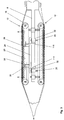
- a winding mandrel 1 in a winding device for producing a lining hose 2 for lining channels and pipelines, a winding mandrel 1 comprises a base body 8, preferably attached to an unspecified, cantilevered holding tube, on which at least two guide devices 10, 12 are accommodated, one each have endless circulating belt 14,16.
- an inner film tube 4 is moved by means of draw rollers 5 in a feed direction A, on the at least one sliver 6, which is impregnated with liquid reaction resin, is wound overlapping by a rotating winding body, which is not shown in more detail in the figures for illustrative reasons.
- the first Guide device 10 fixed to the frame coupled to the base body 8
- the circulating belt 16 of the second guide means 12 is movable in a direction perpendicular to the feed direction A plane and is urged by pressure means 18, 118 with a preferably substantially constant force from the top of the body 8 away in order to generate in the inner film tube a constant voltage if possible.
- Frame-fixed here is to be understood that the respective elements during production firmly connected to the base body 8 and can not move in the radial direction.
- Fig. 2 and 3 shown embodiment of the invention of endless circulating belt 16 of the second guide means 12 via a first and a second guide roller 16a, 16b, which are received on a common support body 20 on which the pressure means 18, 118 act.
- these can run on unspecified, on the support body 20 freely rotatably mounted rollers, which are preferably designed as a ball bearing.
- a linear guide 22 is provided, which may comprise, for example, a frame-fixed rod-shaped element, which is guided in a carrier body 20 attached or formed in this sleeve-shaped element, for example, introduced into the support body 20 through hole.
- the support body 20 according to a further embodiment of the invention on the Pressure means 18; 118 on a second base support body 24, which is adapted to adapt the diameter of the winding mandrel 1 to different standard diameter of the inner film tube 4 via an adjusting device 26, in particular via a manually or motor-operated central spindle drive, in a direction perpendicular to the feed direction (A) of the lining tube. 2 extending direction relative to the base body 8 is movable.
- the support body 20 may be as shown in FIG. 2 and 3 shown - a stop 28 be assigned, which limits the movement of the carrier body 20 from the outside of the base body 8 away. This ensures that the belt 16 moves radially exclusively in a preferred range of motion, in which the pressure means generate a substantially constant pressure force.
- the limit stop 28 in the embodiment described above is a limit switch and / or a position sensor 30, upon the actuation of which a warning signal is output and / or an actuating signal is generated, depending on which an actuator 32,
- an electric servo motor or a pneumatic cylinder is activated, which acts in particular on the base support body 24 to the first and second guide means 10, 12, or in winding mandrels with large diameter and other guide means relative to each other together or drive together.
- the pressure means comprise at least one pneumatic spring element 18, in particular a bellows cylinder or a compressed air cylinder, which is connected to a compressed air source 34 preferably arranged in the interior of the main body 8.
- a compressed air source 34 preferably arranged in the interior of the main body 8.
- a plurality of such pneumatic spring elements 18th arranged, of which in FIG. 2 for the sake of simplicity, only two elements are shown.
- a heating device in particular an electrical heating device, for example an ohmic resistance heater, is preferably in the compressed air source 34 , arranged, with which the temperature of the compressed air stored in the compressed air source 34 can be changed.
- the temperature can also be controlled in the case of an electric heater by a temperature control device not shown in detail to a constant value, so that the pressing force - and thus the tension of the inner film tube 4 in the circumferential direction - always has a predetermined, well-defined size during ongoing production.
- the pressure means comprise at least one mechanical spring 118, which has a substantially path-independent spring characteristic.
- a pressure force can be obtained for example by a gas spring, a plate spring or a highly biased coil spring with a comparatively low spring constant, in which case it can be assumed that the pressure force is only substantially constant, since the aforementioned mechanical springs in practice always have a certain path dependence.
- the substantially constant pressure force on the second belt 16 can be generated thereby, that the second guide means 12 in a linear guide or pivoting guide - as in FIG. 5 indicated - hanging on the underside of the main body 8 is added.
- the substantially constant pressure force of the pressure means is generated by the weight of the second guide means 12, which can be increased or decreased by removing or adding additional weights.
- the damping element comprises an oil pressure damper or a gas pressure damper 36, or in the simplest case an apertured pneumatic bellows, which is preferably fastened with its one end to the base carrier body 24 and with its other end to the carrier body 20.
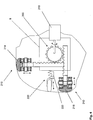
- a first and second guide means 210, 212 are received on the main body 8 of the winding mandrel 1, both of which are mechanically coupled to one another via a central adjusting device 200 received on the main body 8, which belts 216, 216 of the first and second guide means 210, 212 move together by the same travel in the radial direction from the surface of the base body 8 or on this, as in Fig. 4 is shown.
- the pressure means in this embodiment comprise an actuator 218, for example an electric motor and a corresponding gear, or a pneumatic or hydraulic cylinder, which the central adjusting device 200, which is symbolized by a central gear and meshing with this rack, in response to the signals of a Pressure sensor 220 is actuated in such a way that the two belts 214, 216 of the guide means 210, 212 are pressed against the inside of the inner film tube 4 with a substantially constant pressure force.
- an actuator 218 for example an electric motor and a corresponding gear, or a pneumatic or hydraulic cylinder
- the pressure sensor 220 may in this case, for example, a spring-loaded impeller contacting the inside of the inner film tube 4 or a be spring-loaded sliding finger, which - as shown - on the base body 8 or on the carrier body 20 of a guide device 210, 212 may be attached, and whose deflection is detected by an electronic transmitter.
- the actuator 218 is actuated during production operation such that the adjustment device 200 moves the first and second guide means 210, 212 radially inward when the deflection of the pressure sensor 220 is too small, and vice versa.
- the supply of the electrically operated components, such as the actuator and the pressure sensor and possibly also the recorded inside the winding mandrel 1 control electronics can be carried out in an advantageous manner via an accumulator or an inductive coupling of the electrical energy from the outside.
Landscapes
- Engineering & Computer Science (AREA)
- Mechanical Engineering (AREA)
- General Engineering & Computer Science (AREA)
- Manufacturing & Machinery (AREA)
- Moulding By Coating Moulds (AREA)
- Lining Or Joining Of Plastics Or The Like (AREA)
Description
- Die Erfindung betrifft einen Wickeldorn in einer Wickelvorrichtung zur Herstellung eines Auskleidungsschlauchs zur Auskleidung von Kanälen gemäß dem Oberbegriff von Anspruch 1.
- Auf dem Gebiet der grabenlosen Sanierung von defekten Abwasserkanälen werden zunehmend Auskleidungsschläuche eingesetzt, die als "Inliner" bezeichnet werden und aus einem Fasermaterial, insbesondere aus Glasfasergewebe bestehen, welches mit einem flüssigen Reaktionsharz getränkt ist, das nach dem Einziehen des Auskleidungsschlauchs in einen zu sanierenden Kanal und Expandieren desselben mit Hilfe von Druckluft durch Licht einer Strahlungsquelle ausgehärtet wird.
- Ein solcher Auskleidungsschlauch sowie ein Verfahren und eine Vorrichtung zur Herstellung eines solchen sind beispielsweise aus der
DE 198 23 714C2 bekannt. - Die Herstellung des Auskleidungsschlauchs erfolgt dadurch, dass die harzgetränkten Faserbänder in einer Wickelvorrichtung überlappend auf einen für UV-Licht durchlässigen Innenfolienschlauch aufgewickelt werden, der zuvor auf ein fliegend gelagertes Halterohr aufgezogen wird, an dessen Ende sich ein Wickeldorn befindet, über den der Innenfolienschlauch während des Wickelvorgangs bewegt wird. Der Wickeldorn besitz zwei oder mehr Führungseinrichtungen in Form von umlaufenden Riemen, die in radialer Richtung relativ zueinander verfahren werden können, um den Durchmesser des Auskleidungsschlauchs an einen gewünschten Kanaldurchmesser anpassen zu können.
- Hierbei ergibt sich das Problem, dass die in der Regel nahtlos gefertigten Innenfolienschläuche auf die die Faserbänder aufgewickelt werden herstellungsbedingte Umfangstoleranzen von z.B. bis zu ± 14 mm aufweisen können. Der Wickeldorn, über den der Innenfolienschlauch bei der Herstellung des Auskleidungsschlauchs geführt wird, soll hingegen in seinem Durchmesser so eingestellt sein, dass die Schlauchfolie nicht zu fest aber auch nicht zu lose auf den umlaufenden Riemen geführt wird.
- Ein weiteres Problem besteht in diesem Zusammenhang darin, dass der Durchmesser des Wickeldorns nur bei einem frei liegenden Wickeldorn, d.h. vor dem Beginn der Produktion, grundsätzlich verstellbar ist; die gewählte Einstellung des Durchmessers jedoch während der sich anschließenden Produktion nicht mehr verändert werden kann. Fertigungsbedingte Toleranzen des Foliendurchmessers führen dadurch zu einer mehr oder weniger guten Anpassung des Wickeldorns an den tatsächlichen Foliendurchmesser. Ist der Wickeldorn größer als die Folie, wird die Folie übermäßig gedehnt. Ist der Wickeldorn kleiner als die Folie, sitzt die Folie nicht fest genug und kann sich verschieben.
- Dies führt in der Praxis dazu, dass im Innenfolienschlauch Spannungen entstehen, die mitunter zu Falten führen, welche die Festigkeit des Auskleidungsschlauchs nach dem Aushärten in einem zu sanierenden Kanal nachteilig beeinträchtigen.
- Demgemäß ist es eine Aufgabe der vorliegenden Erfindung, mechanische Spannungsunterschiede und damit einhergehende Falten des Innenfolienschlauchs, die durch fertigungsbedingte Durchmessertoleranzen der Folie des Innenfolienschlauchs während der Fertigung des Auskleidungsschlauchs hervorgerufen werden, zu vermeiden.
- Diese Aufgabe wird erfindungsgemäß durch einen Wickeldorn mit den Merkmalen von Anspruch 1 gelöst.
- Weitere Merkmale der Erfindung sind in den Unteransprüchen enthalten.
- Gemäß der Erfindung werden ein, oder bei großen Wickeldornen für Auskleidungsschläuchen mit Normdurchmessern (DN) von mehr als 600 mm auch zwei, Riemen des Wickeldorns gefedert gelagert. Die Spannung auf den Innenfolienschlauch in radialer Richtung, d.h. in Richtung quer zur Vorschubrichtung bleibt dadurch auch dann stets im Wesentlichen konstant, wenn sich der Durchmesser des Innenfolienschlauchs fertigungsbedingt ändert. Anders ausgedrückt justiert sich der Durchmesser des Wickeldorns während der laufenden Produktion selbständig nach, so dass die Folie trotz ihrer fertigungsbedingten Durchmessertoleranzen vor und auch während des Aufwickelns der Faserbänder auf den Innenfolienschlauch immer im Wesentlichen die gleiche Spannung aufweist.
- Wie die Anmelderin in diesem Zusammenhang gefunden hat, wird durch den Ausgleich der fertigungsbedingten Durchmesserveränderungen zwar der Durchmesser des gewickelten Liners im gleichen Maße wie der Durchmesser der Folie verändert, allerdings bereiten derartige Schwankungen im Normdurchmesser (DN) des Liners in der Praxis beim Aufstellen und Aushärten desselben keine Probleme.
- Die Federung des oder der Riemen kann dabei auf unterschiedliche Art und Weise erfolgen, z.B. mit Hilfe von Andruckmitteln, die als Druckluftzylinder, vorzugsweise Balgzylinder, oder auch als mechanische Federn, z.B. Gasdruckfedern oder auch Spiraldruckfedern ausgeführt sind, welche eine vergleichsweise kleine Federkonstante aufweisen und zur Erzeugung der benötigten Andruckkräfte vorgespannt werden, um eine möglichst wegunabhängige, im Wesentlichen konstante Kraft zu erzeugen.
- Die Erfindung wird nachfolgend mit Bezug auf die Zeichnungen anhand von bevorzugten Ausführungsformen beschrieben.
- In den Zeichnungen zeigen:
- Fig. 1
- eine schematische Seitendarstellung einer Wickelvorrichtung mit einem erfindungsgemäßen Wickeldorn während der Produktion eines Auskleidungsschlauchs,
- Fig. 2
- eine schematische Detailansicht einer ersten Ausführungsform der Erfindung, bei der die Andruckmittel als pneumatische Federelemente ausgestaltet sind, die mit einer Druckluftquelle verbunden sind,
- Fig. 3
- eine schematische seitliche Detailansicht einer zweiten Ausführungsform der Erfindung, bei der die Andruckmittel als Gasdruckfedern ausgestaltet sind,
- Fig. 4
- eine schematische Darstellung einer weiteren Ausführungsform der Erfindung, bei der die Andruckmittel als Aktuator ausgestaltet sind, der die Riemen gemeinsam über eine zentrale Verstelleinrichtung in Abhängigkeit von den Signalen eines Drucksensors in radialer Richtung verfährt, um die umfängliche Spannung im Innenfolienschlauch während der Produktion im Wesentlichen konstant zu halten, und
- Fig. 5
- eine schematischer Darstellung einer weiteren Ausführungsform der Erfindung, bei der die Kraft der Andruckmittel durch das Eigengewicht der zweiten Führungseinrichtung bereit gestellt wird, die beweglich und hängend am Grundkörper aufgenommen sind.
- Wie in
Fig. 1 gezeigt ist, umfasst ein Wickeldorn 1 in einer Wickelvorrichtung zur Herstellung eines Auskleidungsschlauchs 2 zur Auskleidung von Kanälen und Rohrleitungen einen vorzugsweise an einem nicht näher bezeichneten, fliegend gelagerten Halterohr befestigten Grundkörper 8, an dem wenigstens zwei Führungseinrichtungen 10, 12 aufgenommen sind, die jeweils einen endlos umlaufenden Riemen 14,16 aufweisen. Über die Riemen 14, 16, die vorzugsweise durch einen nicht näher gezeigten Motor angetrieben werden, wird in bekannter Weise ein Innenfolienschlauch 4 mit Hilfe von Zugwalzen 5 in einer Vorschubrichtung A bewegt, auf den wenigstens ein Faserband 6, das mit flüssigem Reaktionsharz getränkt ist, durch einen umlaufenden Wickelkörper überlappend gewickelt wird, der in den Figuren aus darstellungstechnischen Gründen nicht näher gezeigt ist. - Bei den in den
Figuren 1 bis 3 gezeigten Ausführungsformen der Erfindung ist die erste Führungseinrichtung 10 gestellfest mit dem Grundkörper 8 gekoppelt, und der umlaufende Riemen 16 der zweiten Führungseinrichtung 12 ist in einer senkrecht zur Vorschubrichtung A verlaufenden Ebene bewegbar und wird durch Andruckmittel 18, 118 mit einer vorzugsweise im Wesentlichen konstanten Kraft von der Oberseite des Grundkörpers 8 weg gedrängt, um im Innenfolienschlauch eine nach Möglichkeit konstante Spannung zu erzeugen. Gestellfest ist hierbei so zu verstehen, dass die jeweiligen Elemente während der Produktion fest mit dem Grundkörper 8 verbunden ist und sich in radialer Richtung nicht bewegen kann. - Hierzu wird bei den in
Fig. 2 und3 gezeigten Ausführungsform der Erfindung der endlos umlaufende Riemen 16 der zweiten Führungseinrichtung 12 über eine erste und eine zweite Umlenkrolle 16a, 16b geführt, die an einem gemeinsamen Trägerkörper 20 aufgenommen sind, auf welchen die Andruckmittel 18, 118 wirken. Um hierbei einen möglichst leichtgängigen Umlauf der Riemen 14, 16 zu erhalten, können diese auf nicht näher bezeichneten, am Trägerkörper 20 frei drehbar gelagerten Rollen laufen, die vorzugsweise als Kugellager ausgeführt sind. - Um hierbei eine Bewegung des gemeinsamen Trägerkörpers 20 gegenüber dem Grundkörper 8 in radialer Richtung, d.h. vom Zentrum des Grundkörpers 8 weg zu ermöglichen, ohne den Trägerkörper 20 mit den daran aufgenommenen Riemen in Längsrichtung des Trägerkörpers zu bewegen, ist vorzugsweise eine in
Fig. 1 schematisch angedeutete Führung, insbesondere einer Linearführung 22 vorgesehen, welche z.B. ein gestellfestes stabförmiges Element umfassen kann, welches in einem am Trägerkörper 20 befestigten oder in diesem gebildeten hülsenförmigen Element, z.B. einer in den Trägerkörper 20 eingebrachten Durchgangsbohrung, geführt wird. Hierdurch eröffnet sich die Möglichkeit, den Riemen 16 der zweiten Führungseinrichtung 12 in gleicher Weise wie den Riemen 14 der ersten gestellfesten Führungseinrichtung 10 gewünschten Falls durch einen nicht näher gezeigten Antriebsmotor anzutreiben. - Wie weiterhin in den Darstellungen der
Figuren 2 und3 gezeigt ist, kann sich der Trägerkörper 20 gemäß einer weiteren Ausführungsform der Erfindung über die Andruckmittel 18; 118 an einem zweiten Basis-Trägerkörper 24 abstützen, der zur Anpassung des Durchmessers des Wickeldorns 1 an unterschiedliche Normdurchmesser des Innenfolienschlauchs 4 über eine Verstelleinrichtung 26, insbesondere über einen manuell oder motorisch betätigten zentralen Spindelantrieb, in einer senkrecht zur Vorschubrichtung (A) des Auskleidungsschlauchs 2 verlaufenden Richtung relativ zum Grundkörper 8 bewegbar ist. Hierdurch ergibt sich der Vorteil, dass sich der Durchmesser des erfindungsgemäßen Wickeldorns vor einem Produktionsauftrag in kürzester Zeit auf einen neuen Normdurchmesser einstellen lässt. - Bei den zuvor beschriebenen Ausführungsformen der Erfindung kann dem Trägerkörper 20 - wie in
Figur 2 und3 gezeigt - ein Anschlag 28 zugeordnet sein, der die Bewegung des Trägerkörpers 20 von der Außenseite des Grundkörpers 8 weg begrenzt. Hierdurch wird sichergestellt, dass sich der Riemen 16 radial ausschließlich in einem bevorzugten Bewegungsbereich bewegt, in dem die Andruckmittel eine im Wesentlichen konstante Andruckkraft erzeugen. - Nach einem weiteren der Erfindung zu Grunde liegenden Gedanken ist dem Anschlag 28 bei der zuvor beschriebenen Ausführungsform ein Endschalter und/oder ein Positionssensor 30 angeordnet, bei dessen Betätigung ein Warnsignal ausgegeben und/oder ein Stellsignal erzeugt wird, in Abhängigkeit von welchem ein Stellantrieb 32, beispielsweise ein elektrischer Stellmotor oder ein Pneumatikzylinder, aktiviert wird, welcher insbesondere auf den Basis-Trägerkörper 24 wirkt, um die erste und zweite Führungseinrichtung 10, 12, bzw. bei Wickeldornen mit großem Durchmesser auch weitere Führungseinrichtungen relativ zueinander gemeinsam auseinander oder zusammen zu fahren.
- Bei der bevorzugten, in
Figur 2 gezeigten Ausführungsform der Erfindung umfassen die Andruckmittel wenigstens ein pneumatisches Federelement 18, insbesondere einen Balgzylinder oder einen Druckluftzylinder, welches mit einer vorzugsweise im Inneren des Grundkörpers 8 angeordneten Druckluftquelle 34 verbunden ist. Hierbei sind über die Länge des Grundkörpers 8 vorzugsweise mehrere solcher pneumatischer Federelemente 18 angeordnet, von denen inFigur 2 der Einfachheit halber lediglich zwei Elemente gezeigt sind. Durch Erhöhen oder Erniedrigen des Luftdrucks in der Druckluftquelle 34, was im einfachsten Falle über ein nicht näher dargestelltes Ventil und einen Druckluftkompressor erfolgen kann, lässt sich die Andruckkraft, die durch die Balgzylinder, bzw. Druckluftzylinder 18 auf den umlaufenden Riemen 16 der zweiten Führungseinrichtung 12 ausgeübt wird, auf einen gewünschten Wert erhöhen oder erniedrigen. - Um hierbei auch im Nachhinein während der laufenden Produktion die Andruckkraft auf den Innenfolienschlauch 4 bei Bedarf zu erhöhen oder zu erniedrigen, beispielsweise um Temperaturschwankungen in der Produktionsstätte zu kompensieren, ist vorzugsweise in der Druckluftquelle 34 eine Heizeinrichtung, insbesondere eine elektrische Heizeinrichtung, beispielsweise eine ohmsche Widerstandsheizung, angeordnet, mit welcher sich die Temperatur der in der Druckluftquelle 34 gespeicherten Druckluft verändern lässt. Die Temperatur kann im Falle einer elektrischen Heizeinrichtung ferner durch eine nicht näher gezeigte Temperaturregelungseinrichtung auch auf einen konstanten Wert geregelt werden, sodass die Andruckkraft - und damit die Spannung des Innenfolienschlauchs 4 in Umfangsrichtung - während der laufenden Produktion stets eine vorgegebene, wohl definierte Größe besitzt.
- Gemäß einer weiteren Ausführungsform der Erfindung, die sich besonders vorteilhaft zum Einsatz in rein mechanisch betätigten, nicht angetriebenen Wickeldornen 1 eignet, umfassen die Andruckmittel wenigstens eine mechanische Feder 118, die eine im Wesentlichen wegunabhängige Federkennline aufweist. Eine solche Andruckkraft lässt sich beispielsweise durch eine Gasdruckfeder, eine Tellerfeder oder eine stark vorgespannte Spiralfeder mit einer vergleichsweise geringen Federkonstante erhalten, wobei in diesem Falle davon auszugehen ist, dass die Andruckkraft nur im Wesentlichen konstant ist, da die zuvor genannten mechanischen Federn in der Praxis stets eine gewisse Wegabhängigkeit besitzen.
- Nach einem weiteren der Erfindung zugrunde liegenden Gedanken kann die im Wesentlichen konstante Andruckkraft auf den zweiten Riemen 16 dadurch erzeugt werden, dass die zweite Führungseinrichtung 12 in einer Linearführung oder auch Schwenkführung - wie in
Figur 5 angedeutet - hängend an der Unterseite des Grundkörpers 8 aufgenommen ist. Die im Wesentlichen konstante Andruckskraft der Andruckmittel wird hierbei durch das Eigengewicht der zweiten Führungseinrichtung 12 erzeugt, welches durch Entfernen oder Hinzufügen von Zusatzgewichten erhöht oder erniedrigt werden kann. - Bei der zuletzt beschriebenen Ausführungsform sowie auch bei den zuvor beschriebenen Ausführungsformen der Erfindung ist es weiterhin von Vorteil, wenn die Bewegung des Riemens 16 der zweiten Führungseinrichtung 12 durch ein Dämpfungselement 36 gedämpft wird, das zwischen dem Grundkörper 8 und der zweiten Führungseinrichtung 12 wirkt. Bei der in
Figur 5 gezeigten Ausführungsform der Erfindung umfasst das Dämpfungselement einen Öldruckdämpfer oder einen Gasdruckdämpfer 36, bzw. im einfachsten Falle einen mit Öffnungen versehenen Luftbalg, der vorzugsweise mit seinem einen Ende am Basis-Trägerkörper 24 und mit seinem anderen Ende am Trägerkörper 20 befestigt ist. - Schließlich kann nach einer weiteren alternativen Ausführungsform der Erfindung am Grundkörper 8 des Wickeldorns 1 eine erste und zweite Führungseinrichtung 210, 212 aufgenommen sein, die beide mechanisch miteinander über eine am Grundkörper 8 aufgenommene zentrale Verstelleinrichtung 200 gekoppelt sind, welche die Riemen 214, 216 der ersten und zweiten Führungseinrichtung 210, 212 gemeinsam um den gleichen Verfahrweg in radialer Richtung von der Oberfläche des Grundkörpers 8 weg oder auf diesen zu bewegt, wie dies in
Fig. 4 gezeigt ist. Die Andruckmittel umfassen bei dieser Ausführungsform einen Aktuator 218, z.B. einen Elektromotor und ein entsprechendes Getriebe, oder einen Pneumatik- oder Hydraulikzylinder, welcher die zentrale Verstelleinrichtung 200, die durch ein zentrales Zahnrad und in dieses eingreifende Zahnstangen symbolisiert ist, in Abhängigkeit von den Signalen eines Drucksensors 220 in der Weise betätigt, dass die beiden Riemen 214, 216 der Führungseinrichtungen 210, 212 mit einer im Wesentlichen konstanten Andruckkraft an die Innenseite des Innenfolienschlauchs 4 angedrückt werden. Der Drucksensor 220 kann hierbei z.B. ein die Innenseite des Innenfolienschlauchs 4 kontaktierendes federbelastetes Laufrad oder ein federbelasteter Gleitfinger sein, der - wie gezeigt - am Grundkörper 8 oder auch am Trägerkörper 20 einer Führungseinrichtung 210, 212 befestigt sein kann, und dessen Auslenkung durch einen elektronischen Messwertgeber erfasst wird. In Abhängigkeit von den Signalen des Drucksensors 220 wird der Aktuator 218 während des Produktionsbetriebs in der Weise betätigt, dass die Verstelleinrichtung 200 die erste und zweite Führungseinrichtung 210, 212 radial nach innen fährt, wenn die Auslenkung des Drucksensors 220 zu klein ist, und umgekehrt. Die Versorgung der elektrisch betätigten Bauteile, wie z.B. der Aktuator und der Drucksensor sowie ggf. auch die im Inneren des Wickeldorns 1 aufgenommene Steuerungselektronik kann dabei in vorteilhafter Weise über einen Akkumulator oder auch eine Induktive Einkopplung der elektrischen Energie von außen her erfolgen. -
- 1
- Wickeldorn
- 2
- Auskleidungsschlauch
- 4
- Innenfolienschlauch
- 5
- Zugwalzen
- 6
- Faserband
- 8
- Grundkörper
- 10
- erste Führungseinrichtung
- 12
- zweite Führungseinrichtung
- 14
- Riemen der ersten Führungseinrichtung
- 16
- Riemen der zweiten Führungseinrichtung
- 16a
- erste Umlenkrolle
- 16b
- zweite Umlenkrolle
- 18
- Andruckmittel
- 20
- Trägerkörper
- 22
- Führung
- 24
- Basis-Trägerkörper
- 26
- Verstelleinrichtung zur Veränderung des Normdurchmessers
- 28
- Anschlag
- 30
- Positionssensor
- 32
- Stellantrieb
- 34
- Druckluftquelle
- 36
- Dämpfungselement
- 118
- mechanische Feder
- 200
- Verstelleinrichtung zum gemeinsamen auseinanderfahren der Führungseinrichtungen
- 210
- erste Führungseinrichtung der Ausführungsform von
Fig. 4 - 212
- zweite Führungseinrichtung der Ausführungsform von
Fig. 4 - 214
- erster Riemen
- 216
- zweiter Riemen
- 218
- Aktuator
- 220
- Drucksensor
- A
- Vorschubrichtung
Claims (11)
- Wickeldorn (1) in einer Wickelvorrichtung zur Herstellung eines Auskleidungsscblauchs (2) zur Auskleidung von Kanälen und Rohrleitungen, welcher einen Innenfolienschlauch (4) und eine darauf angeordnete Lage aus wenigstens einem überlappend gewickelten Faserband (6) aufweist, das mit einem flüssigen Reaktionsharz getränkt ist, mit einem Grundkörper (8), an dem wenigstens zwei Führungseinrichtungen (10,12) aufgenommen sind, die jeweils einen endlos umlaufenden Riemen (14,16) umfassen über den der Innenfolienscblauch (4) in einer Vorschubrichtung (A) bewegt wird, dadurch gekennzeichnet, dass
die erste Führungseinrichtung (10) gestellfest mit dem Grundkörper (8) gekoppelt ist, und dass der umlaufende Riemen (16) der zweiten Führungseinrichtung (12) in einer senkrecht zur Vorschubrichtung (A) verlaufenden Ebene bewegbar ist und durch Andruckmittel (18; 118) mit einer vorzugsweise im Wesentlichen konstanten Kraft von der Oberseite des Grundkörpers (8) weg gedrängt wird. - Wickeldorn nach Anspruch 1,
dadurch gekennzeichnet, dass
der endlos umlaufende Riemen (16) der zweiten Führungseinrichtung (12) über eine erste und eine zweite Umlenkrolle (16a, 16b) geführt ist, die an einem gemeinsamen Trägerkörper (20) aufgenommen sind, auf welchen die Andruckmittel (18;118) wirken. - Wickeldorn nach Anspruch 2,
dadurch gekennzeichnet, dass
der gemeinsame Trägerkörper (20) gegenüber dem Grundkörper (8) in einer Führung (22), insbesondere einer Linearführung in radialer Richtung bewegbar geführt ist. - Wickeldorn nach Anspruch 2 oder 3,
dadurch gekennzeichnet, dass
sich der Trägerkörper (20) über die Andruckmittel (18; 118) an einem zweiten Basis-Trägerkörper (24) abstützt, der zur Anpassung des Durchmessers des Wickeldorns (1) an unterschiedliche Normdurchmesser des Innenfolienschlauchs (4) über eine Verstelleinrichtung (26), insbesondere über einen Spindelantrieb, in einer senkrecht zur Vorschubrichtung (A) des Auskleidungsschlauchs (2) verlaufenden Richtung relativ zum Grundkörper (8) bewegbar ist. - Wickeldorn nach einem der Ansprüche 2 bis 4,
dadurch gekennzeichnet, dass
dem Trägerkörper (20) ein Anschlag (28) zugeordnet ist, welcher die Bewegung des Trägerkörpers (20) von der Außenseite des Grundkörpers (8) weg begrenzt. - Wickeldorn nach einem der Ansprüche 1 bis 5,
dadurch gekennzeichnet, dass
dem Anschlag (28) ein Endschalter und/oder ein Positionssensor (30) zugeordnet ist, bei dessen Betätigung ein Warnsignal ausgegeben und/oder ein Stellsignal erzeugt wird, in Abhängigkeit von welchem ein Stellantrieb (32) zum radialen Auseinanderfahren oder Zusammenfahren der ersten und zweiten Führungseinrichtung (10, 12) oder weiterer Führungseinrichtungen aktiviert wird. - Wickeldorn nach einem der vorhergehenden Ansprüche,
dadurch gekennzeichnet, dass
das die Andruckmittel wenigstens ein pneumatisches Federelement (18), insbesondere einen Balgzylinder oder einen Druckluftzylinder, umfassen, welches mit einer vorzugsweise im Inneren des Grundkörpers (8) angeordneten Druckluftquelle (34) verbindbar ist. - Wickeldorn nach Anspruch 7,
dadurch gekennzeichnet, dass
der Druckluftquelle (34) eine Heizeinrichtung, insbesondere eine elektrische Heizeinrichtung, zugeordnet ist, mittels welcher die Temperatur der in der Druckluftquelle (34) gespeicherten Druckluft veränderbar ist. - Wickeldorn nach einem der Ansprüche 1 bis 6,
dadurch gekennzeichnet, dass
die Andruckmittel wenigstens eine mechanische Feder (118) mit einer im Wesentlichen wegunabhängigen Federkennline, insbesondere eine Gasdruckfeder, eine Tellerfeder oder eine vorgespannte Spiralfeder, umfassen. - Wickeldorn nach einem der Ansprüche 1 bis 5,
dadurch gekennzeichnet, dass
die zweite Fübrungseinrichtung (12) hängend an der Unterseite des Grundkörpers (8) aufgenommen ist und die im Wesentlichen konstante Kraft der Andruckmittel durch das Eigengewicht der zweiten Führungseinrichtung (12) bereit gestellt wird. - Wickeldorn nach einem der vorhergehenden Ansprüche,
dadurch gekennzeichnet, dass
ein Dämpfungselement (36) zum Dämpfen der Bewegung der zweiten Führungseinrichtung (12) vorgesehen ist, das zwischen dem Grundkörper (8) und der zweiten Fübrungseinrichtung (12) wirkt.
Applications Claiming Priority (1)
| Application Number | Priority Date | Filing Date | Title |
|---|---|---|---|
| DE102015014729.3A DE102015014729B4 (de) | 2015-11-17 | 2015-11-17 | Wickeldorn in einer Wickelvorrichtung zur Herstellung eines Auskleidungsschlauchs zur Auskleidung von Kanälen und Rohrleitungen |
Publications (2)
| Publication Number | Publication Date |
|---|---|
| EP3178633A1 EP3178633A1 (de) | 2017-06-14 |
| EP3178633B1 true EP3178633B1 (de) | 2018-09-26 |
Family
ID=57144707
Family Applications (1)
| Application Number | Title | Priority Date | Filing Date |
|---|---|---|---|
| EP16002161.4A Active EP3178633B1 (de) | 2015-11-17 | 2016-10-06 | Wickeldorn in einer wickelvorrichtung zur herstellung eines auskleidungsschlauchs zur auskleidung von kanälen und rohrleitungen |
Country Status (3)
| Country | Link |
|---|---|
| US (1) | US10295090B2 (de) |
| EP (1) | EP3178633B1 (de) |
| DE (1) | DE102015014729B4 (de) |
Families Citing this family (4)
| Publication number | Priority date | Publication date | Assignee | Title |
|---|---|---|---|---|
| DE102015012791B4 (de) * | 2015-10-05 | 2023-08-10 | Brandenburger Liner Gmbh & Co. Kg | Verfahren zur Herstellung eines Auskleidungsschlauchs zur Auskleidung von Rohrleitungen sowie eine Vorrichtung zur Durchführung des Verfahrens |
| CN113459354A (zh) * | 2021-07-06 | 2021-10-01 | 哈尔滨理工大学 | 一种紫外光固化管道修复内衬软管及其缠绕式生产工艺 |
| CN115071114B (zh) * | 2022-06-21 | 2024-03-26 | 湖北本本科技有限公司 | 一种橡胶软管水包布缠绕设备 |
| DE102023100843A1 (de) | 2023-01-16 | 2024-07-18 | Relineeurope Gmbh | Verfahren zur Herstellung eines Auskleidungsschlauchs zur Sanierung fluidführender Leitungssysteme |
Family Cites Families (11)
| Publication number | Priority date | Publication date | Assignee | Title |
|---|---|---|---|---|
| BE534294A (de) * | 1954-09-04 | |||
| GB802713A (en) * | 1955-11-29 | 1958-10-08 | Oscar Vilhelm Plym | Improvements in or relating to the manufacture of hollow fibrous reinforced synthetic plastic articles |
| US3570749A (en) * | 1968-08-09 | 1971-03-16 | Showa Denko Kk | Heavy duty bags |
| US3627615A (en) * | 1970-02-11 | 1971-12-14 | Automation Ind Inc | Machine for manufacturing ducting |
| US3950213A (en) * | 1974-11-07 | 1976-04-13 | The Wiremold Company | Machine for manufacturing insulated duct |
| US4054474A (en) * | 1976-03-18 | 1977-10-18 | Aluminum Company Of America | Shrink wrapping |
| US5273611A (en) * | 1992-05-04 | 1993-12-28 | Sig-A-Rap | Apparatus for applying a continuous film to a pipeline |
| DE19823714C2 (de) | 1998-05-27 | 2000-07-06 | Joachim Brandenburger | Wickelvorrichtung zum Herstellen eines Schlauches |
| DE102009050084A1 (de) * | 2009-10-20 | 2011-07-28 | Fasel, Albert, 65520 | Mehrschichtiger Schlauch mit einer schlauchförmigen Innenfolie, Vorrichtung und Verfahren zu dessen Herstellung sowie dessen Verwendung |
| DE102010018479A1 (de) | 2010-04-28 | 2011-11-03 | Brandenburger Patentverwertung Gdbr. | Auskleidungsschlauch und Verfahren zur Sanierung einer defekten Rohrleitung sowie Verfahren zur Herstellung eines solchen. |
| DE102013014796A1 (de) * | 2013-09-09 | 2015-03-12 | Brandenburger Patentverwertung GbR (vertretungsberechtigter Gesellschafter: Wilhelm Leo Betz, 76887 Bad Bergzabern) | Auskleidungsschlauch mit einem überlappend durch Klebeband verbundenen Außenfolienschlauch zur Auskleidung von Rohrleitungen und Verfahren zur Herstellung eines solchen |
-
2015
- 2015-11-17 DE DE102015014729.3A patent/DE102015014729B4/de active Active
-
2016
- 2016-10-06 EP EP16002161.4A patent/EP3178633B1/de active Active
- 2016-11-09 US US15/346,897 patent/US10295090B2/en active Active
Also Published As
| Publication number | Publication date |
|---|---|
| DE102015014729B4 (de) | 2026-05-13 |
| US10295090B2 (en) | 2019-05-21 |
| US20170138512A1 (en) | 2017-05-18 |
| DE102015014729A1 (de) | 2017-05-18 |
| EP3178633A1 (de) | 2017-06-14 |
Similar Documents
| Publication | Publication Date | Title |
|---|---|---|
| EP3178633A1 (de) | Wickeldorn in einer wickelvorrichtung zur herstellung eines auskleidungsschlauchs zur auskleidung von kanälen und rohrleitungen | |
| DE10360471B4 (de) | Verfahren und Vorrichtung zum Aufbringen einer Verstärkung auf ein Kunststoffrohr durch ein Wickelschweißverfahren | |
| DE102014100711A1 (de) | Verfahren und Vorrichtung zur Herstellung von Rohrschalen sowie damit hergestellte Rohrschale | |
| EP0406876B1 (de) | Vorrichtung zur Sanierung von Abflussrohren mit einem verharzten Innenrohr | |
| DE10324187A1 (de) | Kombirolle für Rohrextrusionsanlage | |
| EP3170646B1 (de) | Verfahren zur herstellung eines auskleidungsschlauchs zur auskleidung von rohrleitungen sowie vorrichtung zur durchführung des verfahrens | |
| DE19935402A1 (de) | Verfahren und Vorrichtung zur dichten Befestigung eines Schlauchstückes aus elastomerem Werkstoff an einem Anschlußteil | |
| EP0866017B1 (de) | Vorrichtung zum Aufspannen eines Hülsenkörpers auf einen drehbar angetriebenen Rohrkörper | |
| CH708244A2 (de) | Drahtseil sowie ein Verfahren zu dessen Herstellung. | |
| EP2316635B1 (de) | Ziehvorrichtung zum Ziehen eines Wickeldornes aus einem auf dem Wickeldorn aufgewickelten Wickelprodukt | |
| DE102006055605A1 (de) | Reifenmontiervorrichtung | |
| EP3290370B1 (de) | Drahtlaufvorrichtung | |
| DE102005050008B4 (de) | Vorrichtung und Verfahren zum Wickeln von endlosen Schraubenfedern | |
| EP1494254A1 (de) | Kraftübertragungselement, Verfahren zu dessen Herstellung und Vorrichtung zur Durchführung des Verfahrens | |
| WO2016087012A1 (de) | Spindel für einen wickler | |
| DE2038112A1 (de) | Verfahren und Vorrichtung zur Herstellung eines Giessharzrohres mit Glasfaserverstaerkung im Schleudergiessverfahren | |
| EP1225143A2 (de) | Vorrichtung zum kontinuierlichen Aufwickeln einer Faserstoffbahn | |
| DE2220159C3 (de) | Wickelwelle zum Aufwickeln von Bändern | |
| DE3128111C2 (de) | Verfahren zum Herstellen von flankenoffenen Keilriemen | |
| EP2752381A1 (de) | Wickelstation und Verfahren zu deren Betrieb | |
| DE2700056C2 (de) | Verfahren und Vorrichtung zum Herstellen eines dünnwandigen Schlauches mit wendeiförmiger Bewehrung | |
| EP1818296B1 (de) | Rollenwickelvorrichtung | |
| DE69105913T2 (de) | Verfahren und Vorrichtung zum Ummanteln und unter Druck halten, eines Kerns durch eine Umhüllung aus zusammengesetztem Material. | |
| EP0206310A2 (de) | Verfahren und Vorrichtung zur Herstellung eines Hohlkörpers aus Verbundmaterial | |
| EP4570476A1 (de) | Verfahren und vorrichtung zur herstellung eines gewickelten auskleidungsschlauchs |
Legal Events
| Date | Code | Title | Description |
|---|---|---|---|
| PUAI | Public reference made under article 153(3) epc to a published international application that has entered the european phase |
Free format text: ORIGINAL CODE: 0009012 |
|
| STAA | Information on the status of an ep patent application or granted ep patent |
Free format text: STATUS: THE APPLICATION HAS BEEN PUBLISHED |
|
| AK | Designated contracting states |
Kind code of ref document: A1 Designated state(s): AL AT BE BG CH CY CZ DE DK EE ES FI FR GB GR HR HU IE IS IT LI LT LU LV MC MK MT NL NO PL PT RO RS SE SI SK SM TR |
|
| AX | Request for extension of the european patent |
Extension state: BA ME |
|
| RBV | Designated contracting states (corrected) |
Designated state(s): AL AT BE BG CH CY CZ DE DK EE ES FI FR GB GR HR HU IE IS IT LI LT LU LV MC MK MT NL NO PL PT RO RS SE SI SK SM TR |
|
| STAA | Information on the status of an ep patent application or granted ep patent |
Free format text: STATUS: REQUEST FOR EXAMINATION WAS MADE |
|
| 17P | Request for examination filed |
Effective date: 20171214 |
|
| GRAP | Despatch of communication of intention to grant a patent |
Free format text: ORIGINAL CODE: EPIDOSNIGR1 |
|
| STAA | Information on the status of an ep patent application or granted ep patent |
Free format text: STATUS: GRANT OF PATENT IS INTENDED |
|
| RIC1 | Information provided on ipc code assigned before grant |
Ipc: B29C 63/10 20060101AFI20180417BHEP |
|
| INTG | Intention to grant announced |
Effective date: 20180504 |
|
| GRAS | Grant fee paid |
Free format text: ORIGINAL CODE: EPIDOSNIGR3 |
|
| GRAA | (expected) grant |
Free format text: ORIGINAL CODE: 0009210 |
|
| STAA | Information on the status of an ep patent application or granted ep patent |
Free format text: STATUS: THE PATENT HAS BEEN GRANTED |
|
| AK | Designated contracting states |
Kind code of ref document: B1 Designated state(s): AL AT BE BG CH CY CZ DE DK EE ES FI FR GB GR HR HU IE IS IT LI LT LU LV MC MK MT NL NO PL PT RO RS SE SI SK SM TR |
|
| REG | Reference to a national code |
Ref country code: GB Ref legal event code: FG4D Free format text: NOT ENGLISH |
|
| REG | Reference to a national code |
Ref country code: CH Ref legal event code: EP |
|
| REG | Reference to a national code |
Ref country code: DE Ref legal event code: R082 Ref document number: 502016002036 Country of ref document: DE Representative=s name: REBLE & KESSELHUT PARTNERSCHAFTSGESELLSCHAFT V, DE Ref country code: AT Ref legal event code: REF Ref document number: 1045488 Country of ref document: AT Kind code of ref document: T Effective date: 20181015 |
|
| REG | Reference to a national code |
Ref country code: IE Ref legal event code: FG4D Free format text: LANGUAGE OF EP DOCUMENT: GERMAN |
|
| REG | Reference to a national code |
Ref country code: FR Ref legal event code: PLFP Year of fee payment: 3 |
|
| REG | Reference to a national code |
Ref country code: CH Ref legal event code: NV Representative=s name: PATENTANWALT KOELLIKER GMBH, CH Ref country code: DE Ref legal event code: R096 Ref document number: 502016002036 Country of ref document: DE |
|
| REG | Reference to a national code |
Ref country code: NL Ref legal event code: MP Effective date: 20180926 |
|
| PG25 | Lapsed in a contracting state [announced via postgrant information from national office to epo] |
Ref country code: SE Free format text: LAPSE BECAUSE OF FAILURE TO SUBMIT A TRANSLATION OF THE DESCRIPTION OR TO PAY THE FEE WITHIN THE PRESCRIBED TIME-LIMIT Effective date: 20180926 Ref country code: NO Free format text: LAPSE BECAUSE OF FAILURE TO SUBMIT A TRANSLATION OF THE DESCRIPTION OR TO PAY THE FEE WITHIN THE PRESCRIBED TIME-LIMIT Effective date: 20181226 Ref country code: BG Free format text: LAPSE BECAUSE OF FAILURE TO SUBMIT A TRANSLATION OF THE DESCRIPTION OR TO PAY THE FEE WITHIN THE PRESCRIBED TIME-LIMIT Effective date: 20181226 Ref country code: FI Free format text: LAPSE BECAUSE OF FAILURE TO SUBMIT A TRANSLATION OF THE DESCRIPTION OR TO PAY THE FEE WITHIN THE PRESCRIBED TIME-LIMIT Effective date: 20180926 Ref country code: RS Free format text: LAPSE BECAUSE OF FAILURE TO SUBMIT A TRANSLATION OF THE DESCRIPTION OR TO PAY THE FEE WITHIN THE PRESCRIBED TIME-LIMIT Effective date: 20180926 Ref country code: GR Free format text: LAPSE BECAUSE OF FAILURE TO SUBMIT A TRANSLATION OF THE DESCRIPTION OR TO PAY THE FEE WITHIN THE PRESCRIBED TIME-LIMIT Effective date: 20181227 Ref country code: LT Free format text: LAPSE BECAUSE OF FAILURE TO SUBMIT A TRANSLATION OF THE DESCRIPTION OR TO PAY THE FEE WITHIN THE PRESCRIBED TIME-LIMIT Effective date: 20180926 |
|
| REG | Reference to a national code |
Ref country code: LT Ref legal event code: MG4D |
|
| PG25 | Lapsed in a contracting state [announced via postgrant information from national office to epo] |
Ref country code: HR Free format text: LAPSE BECAUSE OF FAILURE TO SUBMIT A TRANSLATION OF THE DESCRIPTION OR TO PAY THE FEE WITHIN THE PRESCRIBED TIME-LIMIT Effective date: 20180926 Ref country code: AL Free format text: LAPSE BECAUSE OF FAILURE TO SUBMIT A TRANSLATION OF THE DESCRIPTION OR TO PAY THE FEE WITHIN THE PRESCRIBED TIME-LIMIT Effective date: 20180926 Ref country code: LV Free format text: LAPSE BECAUSE OF FAILURE TO SUBMIT A TRANSLATION OF THE DESCRIPTION OR TO PAY THE FEE WITHIN THE PRESCRIBED TIME-LIMIT Effective date: 20180926 |
|
| PG25 | Lapsed in a contracting state [announced via postgrant information from national office to epo] |
Ref country code: RO Free format text: LAPSE BECAUSE OF FAILURE TO SUBMIT A TRANSLATION OF THE DESCRIPTION OR TO PAY THE FEE WITHIN THE PRESCRIBED TIME-LIMIT Effective date: 20180926 Ref country code: PL Free format text: LAPSE BECAUSE OF FAILURE TO SUBMIT A TRANSLATION OF THE DESCRIPTION OR TO PAY THE FEE WITHIN THE PRESCRIBED TIME-LIMIT Effective date: 20180926 Ref country code: CZ Free format text: LAPSE BECAUSE OF FAILURE TO SUBMIT A TRANSLATION OF THE DESCRIPTION OR TO PAY THE FEE WITHIN THE PRESCRIBED TIME-LIMIT Effective date: 20180926 Ref country code: ES Free format text: LAPSE BECAUSE OF FAILURE TO SUBMIT A TRANSLATION OF THE DESCRIPTION OR TO PAY THE FEE WITHIN THE PRESCRIBED TIME-LIMIT Effective date: 20180926 Ref country code: IS Free format text: LAPSE BECAUSE OF FAILURE TO SUBMIT A TRANSLATION OF THE DESCRIPTION OR TO PAY THE FEE WITHIN THE PRESCRIBED TIME-LIMIT Effective date: 20190126 Ref country code: NL Free format text: LAPSE BECAUSE OF FAILURE TO SUBMIT A TRANSLATION OF THE DESCRIPTION OR TO PAY THE FEE WITHIN THE PRESCRIBED TIME-LIMIT Effective date: 20180926 Ref country code: EE Free format text: LAPSE BECAUSE OF FAILURE TO SUBMIT A TRANSLATION OF THE DESCRIPTION OR TO PAY THE FEE WITHIN THE PRESCRIBED TIME-LIMIT Effective date: 20180926 Ref country code: IT Free format text: LAPSE BECAUSE OF FAILURE TO SUBMIT A TRANSLATION OF THE DESCRIPTION OR TO PAY THE FEE WITHIN THE PRESCRIBED TIME-LIMIT Effective date: 20180926 |
|
| PG25 | Lapsed in a contracting state [announced via postgrant information from national office to epo] |
Ref country code: SK Free format text: LAPSE BECAUSE OF FAILURE TO SUBMIT A TRANSLATION OF THE DESCRIPTION OR TO PAY THE FEE WITHIN THE PRESCRIBED TIME-LIMIT Effective date: 20180926 Ref country code: SM Free format text: LAPSE BECAUSE OF FAILURE TO SUBMIT A TRANSLATION OF THE DESCRIPTION OR TO PAY THE FEE WITHIN THE PRESCRIBED TIME-LIMIT Effective date: 20180926 Ref country code: PT Free format text: LAPSE BECAUSE OF FAILURE TO SUBMIT A TRANSLATION OF THE DESCRIPTION OR TO PAY THE FEE WITHIN THE PRESCRIBED TIME-LIMIT Effective date: 20190126 |
|
| REG | Reference to a national code |
Ref country code: BE Ref legal event code: MM Effective date: 20181031 |
|
| REG | Reference to a national code |
Ref country code: DE Ref legal event code: R097 Ref document number: 502016002036 Country of ref document: DE |
|
| PG25 | Lapsed in a contracting state [announced via postgrant information from national office to epo] |
Ref country code: LU Free format text: LAPSE BECAUSE OF NON-PAYMENT OF DUE FEES Effective date: 20181006 |
|
| REG | Reference to a national code |
Ref country code: IE Ref legal event code: MM4A |
|
| PG25 | Lapsed in a contracting state [announced via postgrant information from national office to epo] |
Ref country code: DK Free format text: LAPSE BECAUSE OF FAILURE TO SUBMIT A TRANSLATION OF THE DESCRIPTION OR TO PAY THE FEE WITHIN THE PRESCRIBED TIME-LIMIT Effective date: 20180926 Ref country code: MC Free format text: LAPSE BECAUSE OF FAILURE TO SUBMIT A TRANSLATION OF THE DESCRIPTION OR TO PAY THE FEE WITHIN THE PRESCRIBED TIME-LIMIT Effective date: 20180926 |
|
| PLBE | No opposition filed within time limit |
Free format text: ORIGINAL CODE: 0009261 |
|
| STAA | Information on the status of an ep patent application or granted ep patent |
Free format text: STATUS: NO OPPOSITION FILED WITHIN TIME LIMIT |
|
| PG25 | Lapsed in a contracting state [announced via postgrant information from national office to epo] |
Ref country code: BE Free format text: LAPSE BECAUSE OF NON-PAYMENT OF DUE FEES Effective date: 20181031 |
|
| 26N | No opposition filed |
Effective date: 20190627 |
|
| PG25 | Lapsed in a contracting state [announced via postgrant information from national office to epo] |
Ref country code: SI Free format text: LAPSE BECAUSE OF FAILURE TO SUBMIT A TRANSLATION OF THE DESCRIPTION OR TO PAY THE FEE WITHIN THE PRESCRIBED TIME-LIMIT Effective date: 20180926 Ref country code: IE Free format text: LAPSE BECAUSE OF NON-PAYMENT OF DUE FEES Effective date: 20181006 |
|
| REG | Reference to a national code |
Ref country code: DE Ref legal event code: R082 Ref document number: 502016002036 Country of ref document: DE Representative=s name: REBLE & KESSELHUT PARTNERSCHAFTSGESELLSCHAFT V, DE Ref country code: DE Ref legal event code: R081 Ref document number: 502016002036 Country of ref document: DE Owner name: BRANDENBURGER LINER GMBH & CO. KG, DE Free format text: FORMER OWNER: BRANDENBURGER PATENTVERWERTUNG GBR, 76829 LANDAU, DE |
|
| PG25 | Lapsed in a contracting state [announced via postgrant information from national office to epo] |
Ref country code: MT Free format text: LAPSE BECAUSE OF FAILURE TO SUBMIT A TRANSLATION OF THE DESCRIPTION OR TO PAY THE FEE WITHIN THE PRESCRIBED TIME-LIMIT Effective date: 20180926 |
|
| PG25 | Lapsed in a contracting state [announced via postgrant information from national office to epo] |
Ref country code: TR Free format text: LAPSE BECAUSE OF FAILURE TO SUBMIT A TRANSLATION OF THE DESCRIPTION OR TO PAY THE FEE WITHIN THE PRESCRIBED TIME-LIMIT Effective date: 20180926 |
|
| PG25 | Lapsed in a contracting state [announced via postgrant information from national office to epo] |
Ref country code: HU Free format text: LAPSE BECAUSE OF FAILURE TO SUBMIT A TRANSLATION OF THE DESCRIPTION OR TO PAY THE FEE WITHIN THE PRESCRIBED TIME-LIMIT; INVALID AB INITIO Effective date: 20161006 Ref country code: CY Free format text: LAPSE BECAUSE OF FAILURE TO SUBMIT A TRANSLATION OF THE DESCRIPTION OR TO PAY THE FEE WITHIN THE PRESCRIBED TIME-LIMIT Effective date: 20180926 Ref country code: MK Free format text: LAPSE BECAUSE OF NON-PAYMENT OF DUE FEES Effective date: 20180926 |
|
| GBPC | Gb: european patent ceased through non-payment of renewal fee |
Effective date: 20201006 |
|
| PG25 | Lapsed in a contracting state [announced via postgrant information from national office to epo] |
Ref country code: GB Free format text: LAPSE BECAUSE OF NON-PAYMENT OF DUE FEES Effective date: 20201006 |
|
| PGFP | Annual fee paid to national office [announced via postgrant information from national office to epo] |
Ref country code: CH Payment date: 20221027 Year of fee payment: 7 |
|
| P01 | Opt-out of the competence of the unified patent court (upc) registered |
Effective date: 20230417 |
|
| REG | Reference to a national code |
Ref country code: CH Ref legal event code: PL |
|
| PG25 | Lapsed in a contracting state [announced via postgrant information from national office to epo] |
Ref country code: CH Free format text: LAPSE BECAUSE OF NON-PAYMENT OF DUE FEES Effective date: 20231031 |
|
| PG25 | Lapsed in a contracting state [announced via postgrant information from national office to epo] |
Ref country code: CH Free format text: LAPSE BECAUSE OF NON-PAYMENT OF DUE FEES Effective date: 20231031 |
|
| REG | Reference to a national code |
Ref country code: DE Ref legal event code: R082 Ref document number: 502016002036 Country of ref document: DE Representative=s name: KESSELHUT, WOLF, DIPL.-PHYS., DE |
|
| PGFP | Annual fee paid to national office [announced via postgrant information from national office to epo] |
Ref country code: DE Payment date: 20251020 Year of fee payment: 10 |
|
| PGFP | Annual fee paid to national office [announced via postgrant information from national office to epo] |
Ref country code: AT Payment date: 20251021 Year of fee payment: 10 |
|
| PGFP | Annual fee paid to national office [announced via postgrant information from national office to epo] |
Ref country code: FR Payment date: 20251027 Year of fee payment: 10 |