EP3178419A1 - Kopplungseinrichtung für ein zerlegbares medizinisches instrument - Google Patents
Kopplungseinrichtung für ein zerlegbares medizinisches instrument Download PDFInfo
- Publication number
- EP3178419A1 EP3178419A1 EP16200000.4A EP16200000A EP3178419A1 EP 3178419 A1 EP3178419 A1 EP 3178419A1 EP 16200000 A EP16200000 A EP 16200000A EP 3178419 A1 EP3178419 A1 EP 3178419A1
- Authority
- EP
- European Patent Office
- Prior art keywords
- component
- power transmission
- proximal end
- transmission device
- bore
- Prior art date
- Legal status (The legal status is an assumption and is not a legal conclusion. Google has not performed a legal analysis and makes no representation as to the accuracy of the status listed.)
- Granted
Links
- 230000008878 coupling Effects 0.000 title claims abstract description 89
- 238000010168 coupling process Methods 0.000 title claims abstract description 89
- 238000005859 coupling reaction Methods 0.000 title claims abstract description 89
- 230000005540 biological transmission Effects 0.000 claims abstract description 115
- 230000007704 transition Effects 0.000 claims abstract description 8
- 239000000463 material Substances 0.000 claims description 16
- 238000005520 cutting process Methods 0.000 claims description 9
- 238000004519 manufacturing process Methods 0.000 claims description 9
- 238000000034 method Methods 0.000 description 10
- 210000003811 finger Anatomy 0.000 description 7
- 238000004140 cleaning Methods 0.000 description 3
- 238000010586 diagram Methods 0.000 description 2
- 239000002184 metal Substances 0.000 description 2
- 230000002441 reversible effect Effects 0.000 description 2
- 238000005452 bending Methods 0.000 description 1
- 230000015572 biosynthetic process Effects 0.000 description 1
- 230000003247 decreasing effect Effects 0.000 description 1
- 230000001419 dependent effect Effects 0.000 description 1
- 230000001066 destructive effect Effects 0.000 description 1
- 238000011161 development Methods 0.000 description 1
- 230000018109 developmental process Effects 0.000 description 1
- 238000006073 displacement reaction Methods 0.000 description 1
- 238000003754 machining Methods 0.000 description 1
- 230000000750 progressive effect Effects 0.000 description 1
- 230000003068 static effect Effects 0.000 description 1
- 230000001954 sterilising effect Effects 0.000 description 1
- 238000004659 sterilization and disinfection Methods 0.000 description 1
- 238000003860 storage Methods 0.000 description 1
- 210000003813 thumb Anatomy 0.000 description 1
- XLYOFNOQVPJJNP-UHFFFAOYSA-N water Substances O XLYOFNOQVPJJNP-UHFFFAOYSA-N 0.000 description 1
Images


Classifications
-
- A—HUMAN NECESSITIES
- A61—MEDICAL OR VETERINARY SCIENCE; HYGIENE
- A61B—DIAGNOSIS; SURGERY; IDENTIFICATION
- A61B17/00—Surgical instruments, devices or methods, e.g. tourniquets
- A61B17/28—Surgical forceps
- A61B17/29—Forceps for use in minimally invasive surgery
- A61B17/2909—Handles
-
- A—HUMAN NECESSITIES
- A61—MEDICAL OR VETERINARY SCIENCE; HYGIENE
- A61B—DIAGNOSIS; SURGERY; IDENTIFICATION
- A61B17/00—Surgical instruments, devices or methods, e.g. tourniquets
- A61B17/00234—Surgical instruments, devices or methods, e.g. tourniquets for minimally invasive surgery
-
- A—HUMAN NECESSITIES
- A61—MEDICAL OR VETERINARY SCIENCE; HYGIENE
- A61B—DIAGNOSIS; SURGERY; IDENTIFICATION
- A61B17/00—Surgical instruments, devices or methods, e.g. tourniquets
- A61B17/00234—Surgical instruments, devices or methods, e.g. tourniquets for minimally invasive surgery
- A61B2017/00345—Micromachines, nanomachines, microsystems
-
- A—HUMAN NECESSITIES
- A61—MEDICAL OR VETERINARY SCIENCE; HYGIENE
- A61B—DIAGNOSIS; SURGERY; IDENTIFICATION
- A61B17/00—Surgical instruments, devices or methods, e.g. tourniquets
- A61B2017/00367—Details of actuation of instruments, e.g. relations between pushing buttons, or the like, and activation of the tool, working tip, or the like
-
- A—HUMAN NECESSITIES
- A61—MEDICAL OR VETERINARY SCIENCE; HYGIENE
- A61B—DIAGNOSIS; SURGERY; IDENTIFICATION
- A61B17/00—Surgical instruments, devices or methods, e.g. tourniquets
- A61B2017/0046—Surgical instruments, devices or methods, e.g. tourniquets with a releasable handle; with handle and operating part separable
- A61B2017/00464—Surgical instruments, devices or methods, e.g. tourniquets with a releasable handle; with handle and operating part separable for use with different instruments
-
- A—HUMAN NECESSITIES
- A61—MEDICAL OR VETERINARY SCIENCE; HYGIENE
- A61B—DIAGNOSIS; SURGERY; IDENTIFICATION
- A61B17/00—Surgical instruments, devices or methods, e.g. tourniquets
- A61B2017/00526—Methods of manufacturing
-
- A—HUMAN NECESSITIES
- A61—MEDICAL OR VETERINARY SCIENCE; HYGIENE
- A61B—DIAGNOSIS; SURGERY; IDENTIFICATION
- A61B17/00—Surgical instruments, devices or methods, e.g. tourniquets
- A61B17/28—Surgical forceps
- A61B17/29—Forceps for use in minimally invasive surgery
- A61B17/2909—Handles
- A61B2017/2912—Handles transmission of forces to actuating rod or piston
- A61B2017/2919—Handles transmission of forces to actuating rod or piston details of linkages or pivot points
- A61B2017/292—Handles transmission of forces to actuating rod or piston details of linkages or pivot points connection of actuating rod to handle, e.g. ball end in recess
-
- A—HUMAN NECESSITIES
- A61—MEDICAL OR VETERINARY SCIENCE; HYGIENE
- A61B—DIAGNOSIS; SURGERY; IDENTIFICATION
- A61B90/00—Instruments, implements or accessories specially adapted for surgery or diagnosis and not covered by any of the groups A61B1/00 - A61B50/00, e.g. for luxation treatment or for protecting wound edges
- A61B90/08—Accessories or related features not otherwise provided for
- A61B2090/0813—Accessories designed for easy sterilising, i.e. re-usable
Definitions
- the present invention relates to a handling device for forming a collapsible medical instrument and a collapsible medical instrument, wherein the collapsible medical instrument is in particular a collapsible medical instrument for micro-invasive measures.
- disassembly of a medical instrument can significantly simplify cleaning or make extensive or complete cleaning possible in the first place. Further, disassembly, for example, may allow a combination of different handling devices with different shanks and different tools (eg, scissors, forceps, needle holders).
- a distal end of a shaft with a tool and a proximal end of the shaft are releasably mechanically connected to a handling device, respectively.
- a pull rod or other power transmission device is arranged in the shaft.
- the distal end of the power transmission is mechanically coupled to the tool (and often inextricably linked).
- the proximal end of the force transmission device is guided, for example, through a bore in a first component of the handling device and is mechanically coupled to a second component of the handling device which is movable relative to the first component.
- micro-invasive medical instruments results in ever smaller cross-sections and thus a decreasing mechanical robustness.
- the proximal end of a power transmission device can be easily bent.
- An object of the present invention is to provide an improved handling device for forming a collapsible medical instrument, an improved collapsible medical instrument, and an improved method of manufacturing a handling device.
- Embodiments of the present invention are based on the idea of providing, on a handling device, a guiding or supporting device which guides or supports the proximal end of a power transmission device during the coupling operation and thus prevents deformation of the proximal end of the power transmission device.
- a handling device for forming a collapsible medical instrument comprises a first component, a second component, which is movable relative to the first component, a coupling device on the second component, which is designed and arranged to within a working range of positions of the second component with a corresponding coupling device to be coupled at the proximal end of a power transmission device and not to be coupled to a corresponding coupling device at the proximal end of a power transmission device at a release position of the second component, and a guide means on the first component for guiding a corresponding coupling device at the proximal end of a power transmission device within a transfer area between one end of the work area and the release position.
- the handling device is provided and designed, in conjunction with one or more further components, a non-destructively and reversibly dismountable, d. H. readily formally recombinant medical instrument.
- the other components include, for example, a shaft, a pair of scissors, a pair of pliers, a needle holder or other tool connected or connectable to the distal end of the shaft, and a power transmission device.
- the power transmission device is disposed within the shaft or provided for placement within the shaft.
- the distal end of the power transmission device may be inseparably or non-destructively separable mechanically connected to the tool.
- the power transmission device is provided and configured to transmit a force (parallel to the longitudinal direction of the power transmission device) and / or a torque.
- the power transmission device is in particular a pull rod made of metal or another material with low elasticity.
- the power transmission device is in particular coupled to the tool such that a displacement of the power transmission device is associated proximally with a closing, a gripping or a cutting movement of the tool.
- the handling device is provided and designed in particular for or for the formation of a dismountable medical instrument for micro-invasive applications.
- the first component and the second component are in particular designed and arranged such that they can be moved by medical personnel by means of one hand relative to each other.
- the handling device may have a plurality of second components or more than two relatively movable components.
- the first component may be monolithic or composed of two or more elements.
- the first component is in particular mechanically permanently connected or detachably connectable to the proximal end of a shaft.
- the first component is in particular connected or connectable to the proximal end of a shaft such that the shaft can not be moved relative to the first component or can only be rotated about its longitudinal axis.
- the first component has an eye or a handle opening for one or more fingers of a human hand.
- the second component may be monolithic or composed of several elements.
- the second component is pivotable relative to the first component, in particular about a pivot axis defined by a shaft or in another way.
- the second component can be displaceable relative to the first component along a straight or curved path or movable in several spatial directions.
- the second component has an eye or a handle opening for one or more fingers of a human hand.
- the work area comprises a plurality of positions of the second component relative to the first component, which are provided for the intended use of the handling device as part of a collapsible medical instrument. Due to the mechanical coupling of the second component via the power transmission device with a tool, a movement of the second component is accompanied by a movement of the tool, and each position of the second component relative to the first component corresponds to a configuration or position of the tool.
- the working area comprises a first extreme position of the second component relative to the first component, which is provided with a fully closed configuration of a forceps or needle holder or a configuration present at the end of a cutting operation a pair of scissors at the distal end of the collapsible medical instrument.
- the work area further includes a second extreme position associated with a fully open configuration of a forceps or needle holder, or a scissors configuration present at the beginning of a cutting operation at the distal end of the collapsible medical instrument.
- the workspace includes all positions between the two described extreme positions within the workspace.
- the release position of the second component relative to the first component may be positively defined by a stop or two surfaces arranged opposite one another and contacting one another in the release position on the first component and on the second component.
- the handling device is present in a configuration in which the coupling device is not or can not be coupled to the second component with a corresponding coupling device at the proximal end of a power transmission device.
- the coupling device on the second component can be coupled to a corresponding coupling device on the proximal end of a power transmission device by moving the second component relative to the first component, starting from the release position in the transition region toward the working region.
- the coupling device on the second component can be separated from a corresponding coupling device at the proximal end of a power transmission device.
- the coupling device on the second component and a corresponding coupling device on the proximal end of the force transmission device may be designed to allow a clear distinction between two directly adjacent regions in which a coupling is or is not present in an idealized, in particular friction-free, case wherein the boundary between both regions may be formed by the release position or may be close to the release position.
- the boundary between both regions may be formed by the release position or may be close to the release position.
- static friction between surfaces that can touch each other To slide cause, for example, with a movement of the second component relative to the first component is not accompanied by an intended longitudinal movement of the power transmission, but instead the proximal end of the transmission receives a force orthogonal to the longitudinal direction and thereby bent.
- the guide device may guide and support the proximal end of a power transmission device at least in a part of the transition region.
- the guide device can therefore absorb forces that are not provided, which are not parallel to the longitudinal direction of the power transmission device, and thus prevent deformation of the proximal end of the power transmission device.
- the guide device is in particular designed and arranged to guide a corresponding coupling device at the proximal end of a power transmission device within the entire transitional region.
- Guiding the proximal end of a power transmission device within the entire transition region between the release position and the release position facing end of the work area may prevent deformation and damage to the power transmission device.
- the guide device is in particular designed and arranged to guide a corresponding coupling device at the proximal end of a power transmission device at a position within the working range.
- the guide device is in particular designed and arranged to guide a corresponding coupling device at the proximal end of a power transmission device within a part of the work area or within the entire work area.
- a guide of the proximal end of a power transmission device not only within the transition region, but also within a part of the work area or the entire work area can in particular in the case of a pivoting of the second component prevent deformation of the proximal end of a power transmission device.
- the guide device in particular comprises a sliding surface for guiding a corresponding coupling device at the proximal end of a power transmission device.
- the sliding surface is in particular translation-invariant or cylindrically symmetrical or parallel to the intended direction of movement of the corresponding coupling device.
- the sliding surface is in particular arranged so that it touches the surface at each intended position of a corresponding coupling device at the proximal end of a power transmission, without exerting a force or has a small distance from the surface thereof.
- a distance between the sliding surface of the guide device and a surface of a corresponding coupling device at the proximal end of a power transmission device is small, if the contact between the sliding guide and the surface deformation of the power transmission device is required, which causes no plastic deformation or permanent deformation of the power transmission device.
- the sliding surface is in particular designed and arranged such that its mean surface normal is parallel or substantially parallel to a direction of a force which the second component can exert on a coupling device at the proximal end of a power transmission device.
- the sliding surface is arranged in particular on an edge of a web on the first component.
- the web has the shape of a section of a flat plate.
- the web is in particular parallel or substantially parallel to a mean surface normal of the sliding surface.
- the second component in particular has a slot in which the web is arranged on the first component.
- the coupling device on the second component in particular comprises two parallel and mutually opposite grooves in two opposite walls of the slot.
- the grooves are in particular arranged so that they can play and friction with a corresponding coupling device at the proximal end of a power transmission device along a predetermined path relative to the second component.
- the grooves and the path are straight in particular.
- the grooves are arranged, for example, radially to the pivot axis.
- the grooves are in particular designed and arranged such that at the release position of the second component relative to the first component, a corresponding coupling device can be arranged at the proximal end of a power transmission at first ends of the grooves or inserted into first ends of the grooves.
- the sliding surface in particular has the shape of a section of a lateral surface of a circular cylinder.
- a sliding surface in the form of a section of a lateral surface of a circular cylinder can for example be formed as part of an inner surface of a bore.
- the sliding surface is a continuation of an inner surface of a bore into which a force transfer device can be inserted from distal to proximal during assembly or assembly of a collapsible medical instrument and passed through a coupling device at the proximal end of the force transfer device.
- the width of the web and the width of the slot are each smaller than the width of the corresponding Coupling device at the proximal end of a power transmission device, for which the handling device is provided.
- the coupling device is designed in particular for coupling to a spherical, corresponding coupling device at the proximal end of a force transmission device, wherein the width of the web and the width of the slot are each smaller than the diameter of the spherical corresponding coupling device on the proximal End of a power transmission device, for which the handling device is provided.
- the spherical corresponding coupling device projects over the web on one side or on both sides.
- the spherical corresponding coupling means may engage in a groove on an inner wall of the slot or simultaneously in two opposing grooves in two opposite walls of the slot.
- the spherical corresponding coupling device may thus be simultaneously guided by the web or the sliding surface on the web relative to the first component and by the groove or by the grooves on the inner surface of the slot relative to the second component.
- the guide device in particular comprises two opposing sliding surfaces, which are designed and arranged to guide a corresponding coupling device at the proximal end of a power transmission device between them.
- the cross-section of the space bounded by the two opposite sliding surfaces is in particular only slightly larger than the cross-section of the corresponding coupling device at the proximal end of the power transmission device, for which the handling device is provided to allow a play and low-friction guidance.
- the two sliding surfaces are in particular in one direction which is parallel to a plane in which the second component is located. In particular, the two sliding surfaces face each other in a direction orthogonal to a pivot axis about which the second component is pivotable.
- the sliding surfaces in particular the shape of two sections of a lateral surface of a circular cylinder.
- the sliding surfaces are formed by cutouts or regions of an inner surface of a bore in the first component.
- a handling device as described here further comprises a shaft coupling device for the releasable mechanical connection of the handling device to a proximal end of a shaft.
- a collapsible medical instrument comprises a handling device as described here, a shaft whose proximal end is connected to the handling device or is detachably mechanically connectable, and a force transmission device with a coupling device on the second component corresponding to the coupling device at the proximal end of the force transmission device.
- the coupling device at the proximal end of the power transmission device is in particular spherical.
- a method of fabricating a handling device to form a disassemblable medical instrument includes a step of creating a first bore in a first component, wherein the first bore is configured to receive a proximal portion of a force transmitting device, a step of removing material from the first Component of two opposite sides to two parallel planar surfaces, which are parallel to the axis of the first bore and intersect the inner surface of the bore, a step of generating a second bore in a second component, wherein the second bore for receiving a coupling device is provided at the proximal end of a power transmission device and is formed, a step of generating a slot in the first component, wherein the slot is parallel to an axis of the second bore, and wherein the width of the slot is smaller than the diameter of the second bore, and a Step of connecting the first component and the second component such that the second component is movable relative to the first component.
- the method is particularly suitable for manufacturing a handling device, as described here, or a handling device with features described here.
- the steps can be performed in a different order.
- the axis of the first bore is arranged in particular between the two parallel planar surfaces, up to which material is removed on the first component.
- the axis of the second bore is arranged in particular within the slot in the second component.
- the first bore, the second bore, and the slot may each be formed by a machining process, by electrical discharge, laser or water jet cutting, or otherwise. The removal of material on the first component can also take place by means of one of the methods mentioned.
- FIG. 1 shows a schematic representation of a collapsible medical instrument 10, which is provided and designed in particular for use in the context of a micro-invasive measure.
- the proximal end 12 of the medical instrument 10 is formed by a handling device 20.
- the distal end 14 is formed by a tool 16.
- the tool 16 is, for example, a pair of scissors, forceps or needle holders having two or more branches, at least one of which is movable relative to the other and to the shaft 80.
- the handling device 20 comprises a first component 30 and a second component 50, which are connected to each other by a hinge 26.
- the hinge 26 defines a pivot axis 28 orthogonal to the plane of the drawing FIG. 1 ,
- the joint 26 is for example a short shaft, which forms a sliding bearing with the first component 30 and is rigidly connected to the second component 50.
- an eye or handle opening 36 is arranged for one or more fingers of a human hand.
- An eye or grip opening 56 for one or more fingers of a human hand is likewise arranged on the second component 50.
- the eye 36 are provided on the first component 30 for the middle finger, the ring finger or another finger and the eye 56 on the second component 50 for the thumb of the same hand.
- a recess 38 for receiving the proximal end 82 of the shaft 80 is provided on the first component 30 .
- the recess 38 is in FIG. 1 simplified as blind hole indicated.
- locking means By means of an in FIG. 1 Not shown locking means, the proximal end 82 of the shaft 80 are held in the recess 38.
- the first component 30 has a bore 42 in extension of the recess 38. The cross section of the bore 42 is smaller than the cross section of the recess 38.
- a power transmission device 90 for example, a pull rod - arranged in the shaft 80 and in the bore 42.
- the power transmission device 90 is in FIG. 1 indicated by a wide dashed line, since it is arranged inside the shaft 80 and the first component 30 and therefore is not visible from the outside.
- the power transmission device 90 is displaceable in the shaft 80 and in the bore 42 in the direction parallel to the longitudinal axis of the power transmission device 90.
- the power transmission device 90 comprises, for example, metal or other material with low elasticity.
- the power transmission device 90 has in particular a small cross section and therefore a high bending elasticity.
- the power transmission device 90 may be provided and configured in addition to transmitting a torque or rotational movement from the handling device 20 to the tool 16.
- the proximal end 92 of the power transmission device 90 is - as with reference to FIGS. 2 to 10 shown - coupled to the second component 50, so that a movement of the second component 50 is associated with a movement of the power transmission device 90.
- the distal end of the power transmission device 90 is coupled to the tool 16 at the distal end 14 of the medical instrument 10 such that a movement of the power transmission device 90, for example, accompanied by a pivoting movement of a pivoting branch or two pivotable branches of the tool 16.
- the second component 50 and the proximal end 92 of the power transmission device 90 and the distal of the power transmission device 90 and the tool 16 are coupled such that a pivoting movement of the second component 50 toward the first component 30 with a closing, a cross-sectional movement or a cutting movement of the tool 16 at the distal end 14 of the medical instrument 10 is accompanied.
- the medical instrument 10 is non-destructive and reversible dismantled.
- the handling device 20 can be separated from the proximal end 82 of the shaft 80.
- a push button for unlocking the connection between the handling device 20 and shaft 80 is pressed and at the same time or thereafter pulled the proximal end 82 of the shaft 80 from the recess 38 on the first component 30 distally.
- the force transmission device 90 including its proximal end 92 is pulled out distally from the bore 42 in the first component 30.
- the shaft 80 and the tool 16 may be mechanically non-destructively and reversibly releasably connected to each other.
- the distal end of the power transmission device 90 may be permanently connected to the tool 16.
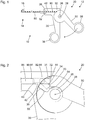
- FIG. 2 shows a schematic representation of parts of the second component 30 and the pivotable member 50 of a handling device 20 for a medical instrument, as for example with reference to FIG FIG. 1 is shown.
- the drawing plane of the FIG. 2 corresponds to the drawing level of FIG. 1 .
- FIG. 2 In contrast to FIG. 1 are in FIG. 2 not only - in solid lines - externally visible features, but also - in Dashed lines - not visible from the outside structures and features inside the handling device 20 indicated.
- the handling device 20 is in particular mirror-symmetrical or substantially mirror-symmetrical to a plane of symmetry parallel to the plane of the drawing FIG. 2 is.
- the handling device 20 comprises a joint 26 which has a pivot axis 28 orthogonal to the plane of the drawing FIG. 2 Are defined. In FIG. 2 only portions of the first component 30 and the second component 50 near the hinge 26 are shown.
- the joint 26 is formed by a shaft or a circular cylindrical or partially circular cylindrical bolt which is play and friction in the first component and rigidly connected to the second component 50 is formed.
- the hinge 26 allows pivotal movement of the second component 50 about the pivot axis 28 relative to the first component 30.
- the first component 30 has a circular cylindrical bore 42, in which in. In FIG. 2 already shown a proximal portion 91 of a power transmission device 90 is used.
- the proximal end 92 of the power transmission device 90 is formed by a spherical or substantially spherical coupling device 94.
- the cross-section of the bore 42 and the cross-sections of the power transmission device 90 including the coupling device 94 at the proximal end 92 of the power transmission device 90 are coordinated so that the power transmission device 90 by the inner surface 43 of the bore 42 play and friction and guided parallel to its axis of symmetry 98th in the bore 42 is displaceable.
- the second component 50 has at its end facing the first component 30 a slot which is parallel to the plane of the FIG. 2 extends.
- parts of the first component 30 are arranged so that in the viewing direction of FIG. 2 the second component 50 are partially arranged in front of and partially behind the parts of the first component 30 arranged in the slot.
- a first web 31 and a second web 33 are arranged on the first component 30.
- a first sliding surface 32 at the straight edge of the first web 31 facing the second web 33 and a second sliding surface 34 at the straight web of the second web 33 facing the first web 31 form a guide device for the coupling device 94 at the proximal end 92 of the power transmission device 90 Positions that are proximal to the in FIG. 2 shown position of the power transmission device 90 are located.
- the sliding surfaces 32, 34 have in particular the shape of two sections of a lateral surface of a circular cylinder with the axis of symmetry 44 and are therefore each concave.
- the sliding surfaces 32, 34 are in particular smooth continuations of the inner surface 43 of the bore 42 to the proximal.
- the axis of symmetry 44 of the sliding surfaces 32, 34 is thus identical to the axis of symmetry 98 of the power transmission device 90.
- Steps 35 are provided on the first component 30 and steps 55 on the second component 50.
- two steps 35 on the first component 30 are arranged parallel and mirror-symmetrically to one another on a side facing the observer and on a side of the first component 30 facing away from the observer.
- two steps 55 are arranged on the second component 50 parallel and mirror-symmetrical to each other on two opposite walls of said slot.
- the second web 33 extends in particular from the steps 35 to the second sliding surface 34.
- FIG. 2 shown position of the second component 50 relative to the first component 30 are the steps 55 on the second component 50 at the steps 35 on the first component 30 at.
- the steps 35 on the first component and the steps 55 on the second component 50 thus form a mechanical stop
- two parallel and opposing walls bounding said slot in the second member 50 are two parallel and opposite each other Grooves 54 are provided.
- the cross-sections of the grooves 54 are selected so that they can receive opposing areas of the coupling device 94.
- the coupling device 94 At the in FIG. 2 illustrated release position of the second component 50 relative to the first component 30 is the coupling device 94 at the proximal end 92 of the power transmission device 90 at the open ends of the grooves 54. Based on this situation or configuration, the power transmission device 90 can be pushed proximally. In this case, the second component 50 is pivoted clockwise about the pivot axis 28, and the coupling device 94 slides into the grooves 54 inside.
- FIG. 3 shows a schematic representation of the first component 30 of the basis of the FIG. 2 illustrated handling device 20.
- the plane of the FIG. 3 corresponds to the drawing level of FIG. 2 .
- the first component 30, but not the second component 50 is shown.
- the webs 31, 33 and the step 35 are therefore visible.
- the sliding surfaces 32, 34 on the mutually facing edges of the webs 31, 33 are concave and therefore also in the illustration of FIG. 3 not visible and indicated only by dashed lines.
- FIG. 4 shows a schematic representation of a section along the in FIG. 3 indicated plane AA through the first component 30.
- the sectional plane AA is orthogonal to the planes of the drawing Figures 2 and 3 and orthogonal to the axis of symmetry 44 of the sliding surfaces 32, 34.
- the sliding surfaces 32, 34 are straight and smooth continuations of the inner surface 43 of the bore 42 in the first component 30, the axis of symmetry 44 of the sliding surfaces 32, 34 simultaneously the axis of symmetry of the inner surface 43 of the bore 42.
- the sliding surfaces 32, 34 are in particular generated simultaneously or in the same operation with the bore 42.
- the diameter of the bore 42 corresponds substantially to the diameter of the coupling device 94 at the proximal end 92 of the power transmission device 90 (see. FIG. 3 ).
- the diameter of the bore 42 is greater than the measured in the direction parallel to the pivot axis 28 thickness of the webs 31, 33rd
- material is removed as a through-bore from two opposite sides of symmetrically or substantially symmetrically.
- material is in two mirror-symmetrical spatial regions 46, one of which in FIG. 4 dashed hatched, abraded.
- the two mirror-symmetrical spatial regions 46 are formed by mirror-symmetrically arranged planar surfaces 47, one of which is in FIG. 4 is indicated by a straight dashed line limited.
- FIG. 5 shows a schematic representation of a section through the second component 50 of the basis of the FIG. 2 illustrated handling device along a sectional plane BB.
- the section plane BB is parallel to the drawing planes of the FIGS. 1 to 3 and at the same time is the plane of symmetry to which the second component 50 is mirror-symmetrical or substantially mirror-symmetrical.
- the cutting plane B-B lies in the mentioned slot 52 in the second component 50.
- the shaft or bolt which forms the hinge 26 penetrates the slot orthogonally. This leaves a shape of the slit, which in the mathematical sense is doubly connected and homeomorphic to a ring.
- the slot 52 has different widths (measured in the direction parallel to the pivot axis 28 and orthogonal to the sectional plane BB) in two areas separated by the step 55.
- a respective groove 54 are arranged on the mutually facing and opposite walls of the slot 52.
- the grooves 54 are parallel to one another and have inner surfaces which essentially have the shape of two sections of the lateral surface of a circular cylinder with the axis of symmetry 64. Deviating from this are at the radially outer or provided facing away from the hinge 26 ends of the grooves 54 chamfers or funnel-shaped inputs.
- FIG. 6 shows a schematic representation of a section along the in FIG. 5 indicated section plane CC by the basis of the Figures 2 and 5 shown second component 50.
- the sectional plane CC is orthogonal to the sectional plane of the BB FIG. 5 , Parallel to the pivot axis 28 and orthogonal to the axis of symmetry 64 of the grooves 54.
- the location of the cutting plane BB of the FIG. 5 to which the second component 50 is mirror-symmetric is in FIG. 6 indicated.
- the slot 52 has two regions of different width, between which the steps 55 are arranged.
- the surface normals of the steps 55 are parallel to the sectional plane BB of FIG. 5 and orthogonal to the pivot axis 28 (see. Figures 2 and 5 ).
- the grooves 54 are in particular simultaneously and prior to the production of the slot 52 by creating a bore 62, whose axis of symmetry of the axis of symmetry 64 of the grooves 54 corresponds generated.
- the axis of symmetry 64 of the bore 62 and the grooves 54 lies in the plane of symmetry of the second component 50 or in the sectional plane BB of the FIG. 5 .
- the slot 52 is bounded in the vicinity of the grooves 54 by two parallel and opposing surfaces 67 whose spacing is less than the diameter of the bore 62.
- FIG. 7 shows a schematic representation of a section along a sectional plane DD by means of the FIGS. 2 to 6 illustrated handling device 20.
- the sectional plane DD corresponds to the sectional plane AA FIG. 4 .
- FIG. 7 a configuration or angular position of the second component 50 relative to the first component 30 is shown, which differs from that of FIGS FIG. 2 differs, and the basis of the FIG. 8 is described.
- the grooves 54 are cut by the sectional plane DD. In the illustrated section invisible contours of the concave surfaces of the grooves 54 are in FIG. 7 indicated by dashed lines.
- the widths of the webs 31, 33 largely correspond to the width of the groove 52 in the vicinity of the grooves 54, so that the webs 31, 33 are guided on the first component 30 with low friction in the slot 52 in the second component 50.
- the coupling device 94 at the proximal end of the power transmission device is wider than the webs 31, 33 on the first component 30 and the slot 52 in the second component 50.
- the coupling device 94 engages in the grooves 54 in the second component 50.
- the sliding surfaces 32, 34 guide and support the coupling device 94 by positively locking a deflection of the coupling device 94 in one direction in the sectional plane D-D.
- FIG. 8 shows a further schematic representation of the basis of the FIGS. 2 to 7 Handling device 20.
- the drawing plane and the type of representation correspond to those of FIG. 2 , In FIG. 8 However, the situation or configuration is shown, which is also in FIG. 7 shown, and different from the one in FIG. 2 shown differs.
- the cutting plane DD of the FIG. 7 is in FIG. 8 indicated.
- the configuration shown is the second component 50, starting from the in FIG. 2 shown release position pivoted by a predetermined angle toward the first component 30. Accordingly, the step 55 on the pivotable component 50 is spaced from the step 35 on the first component 30.
- position of the second component 50 is located, for example, on the in FIG. 2 shown releasing position facing the end of a workspace of positions.
- the work area is formed by all the positions intended for the intended use of the handling device 20 as part of a medical instrument. The intended use is for use in a medical procedure and does not involve disassembly, cleaning, sterilization, assembly and storage of the medical instrument between two uses in medical procedures.
- the coupling device 94 at the proximal end 92 of the power transmission device 90 is fully inserted into the grooves 54 in the second component 50 and is simultaneously in the extremely proximal position in which it is still guided by the sliding surfaces on the webs 31, 33. Within the entire transitional area between the in FIG. 2 shown release position and the in FIG. 8 shown position at one end of the working area, the coupling device 94 is guided and supported at the proximal end 92 of the power transmission device 90 through the sliding surfaces 32, 34.
- FIG. 9 shows a further schematic representation of the basis of the FIGS. 2 to 8 Handling device 20.
- the drawing plane and the type of representation correspond to those of Figures 2 and 8th , In the FIG. 9 However, shown configuration or situation differs from the in the Figures 2 and 8th shown.
- FIG. 9 a configuration or situation is shown, in which the second component 50 is pivoted completely to the first component 30 zoom.
- This position of the second component 50 is located at the to the in FIG. 8 shown position opposite end of the workspace.
- the coupling device 94 at the proximal end 92 of the power transmission device 90 is arranged in the grooves 54.
- the coupling device 94 engages the grooves 54 on the second component 50 at the proximal end 92 of the power transmission device 90.
- This engagement forms a form-locking coupling of the power transmission device 90 with the second component 50, so that a pivoting movement of the second component 50 about the pivot axis 28 is accompanied by a translational movement of the power transmission device 90 in the direction parallel to its axis of symmetry 98.
- not shown devices can be ensured that, for example, only with simultaneous actuation of an unlocking the power transmission device 90 via the in FIG. 8 As shown in the position shown displaced distally and thus the second component 50 on the in FIG. 8 shown angular position up to the in FIG. 2 shown release position can be pivoted.
- the coupling device 94 comes at the proximal end 92 the power transmission device 90 out of engagement with the grooves 54 in the second component 50, so that the power transmission device 90 (in particular together with the shaft 80 - see FIG. FIG. 1 ) can be separated distally from the handling device 20.
- the at the in FIG. 2 shown release position of the second component 50 present position of the power transmission device 90 may correspond to an overtop position of the tool 16 at the distal end 14 of the medical instrument (see. FIG. 1 ).
- FIG. 10 shows a schematic representation of another handling device, which in some features, properties and functions of the FIGS. 2 to 9 illustrated handling device 20 is similar.
- the plane of the drawing and the type of representation correspond to those of the Figures 2 . 8th and 9 ,
- FIG. 10 shown handling device 20 differs from the basis of the FIGS. 2 to 9 illustrated handling device in particular characterized in that the webs 31, 33 extend significantly further to the proximal.
- the webs 31, 33 and thus also the sliding surfaces 32, 34 at the mutually facing edges of the webs 31, 33 so far to the proximal that the coupling device 94 at the proximal end 92 of the power transmission device 90 in the entire working area, ie in the in FIG. 10 shown position of the second component 50 is guided by the sliding surfaces on the webs 31, 33.
- a deformation of the power transmission device 90 is therefore not only in the transition region between the in FIG. 2 shown release position and the in FIG. 8 position shown at the edge of the work area, but also throughout the work area between the in FIG. 8 shown position and in the FIGS. 9 and 10 shown position excluded.
- FIG. 11 shows a schematic flow diagram of several method steps of a method for manufacturing a handling device. Although by means of a method with the basis of FIG. 11 also shown steps, a handling device can be made, the other features, properties or functions than those based on the FIGS. 2 to 10 Having illustrated handling devices, reference numerals will be exemplified below FIGS. 1 to 10 used.
- a first bore 42 is produced in a first component 30 or in a workpiece from which the first component 30 is formed. At the same time or at the same process step or before or after a recess 38 for a proximal end 82 of a shaft 80 can be generated.
- the first bore 42 has a cross section which is only slightly larger than the cross section of a coupling device 94 at the proximal end 92 of a power transmission device 90, for which the handling device 20 is provided.
- a second step 102 material is removed from the first component 30.
- material is removed up to two parallel planar surfaces 47 in two space regions 46 which are arranged symmetrically to one another and symmetrically with respect to the first bore 42.
- the axis 44 of the first bore 42 is arranged in particular parallel to the flat surfaces 47 and in the middle between the flat surfaces 47.
- the distance of the flat surfaces 47, to which material is removed, is smaller than the diameter of the first bore 42, so that the flat surfaces 47 intersect the cross section of the first bore 42. Therefore, as the material 102 is removed, portions of the inner surface 43 of the first bore 42 are removed. Remaining areas of the inner surface 43 of the first bore 42 form sliding surfaces 32, 34 on parallel and opposite edges of two webs 31, 33, which are bounded by the flat surfaces 47.
- a second bore 62 is produced in a second component 50 or in a workpiece from which the second component 50 is formed.
- the cross section of the second bore is slightly larger than the cross section of the coupling device 94 at the proximal end 92 of the power transmission device 90, for which the handling device 20 is provided.
- the cross section of the second bore 62 in the second component 50 corresponds to the cross section of the first bore 42 in the first component 30.
- a slot 52 is created in the second component 50.
- the slot 52 is bounded by two parallel planar surfaces 67 which are parallel to the axis 64 of the second bore 62.
- the axis 64 of the second bore 62 is located midway between the planar surface portions 67 of the slot 52.
- the distance the flat surface portions 67 of the slot 52 is slightly larger than the distance of the flat surfaces 47 and the width of the webs 31, 33 on the first component 30.
- a fifth step 105 the first member 30 and the second member 50 are connected by a hinge so that the second member 50 is pivotable relative to the first member 30 about a pivot axis 28 which is orthogonal to the axis 44 of the first bore 42 in the first component 30 and orthogonal to the axis 64 of the second bore 62 in the second component 50 and thus both orthogonal to the axis of symmetry of the sliding surfaces 32, 34 on the first component 30 and orthogonal to the axis of symmetry of the grooves 54 on the second component 50.
- the order of the steps may differ from that shown.
- the third step 103 and / or the fourth step 104 may be performed before the first step 101 and / or before the second step 102.
- the second step 102 may be performed before the first step 101 and the fourth step 104 before the third step 103.
Landscapes
- Health & Medical Sciences (AREA)
- Life Sciences & Earth Sciences (AREA)
- Surgery (AREA)
- Heart & Thoracic Surgery (AREA)
- Engineering & Computer Science (AREA)
- Biomedical Technology (AREA)
- Nuclear Medicine, Radiotherapy & Molecular Imaging (AREA)
- Medical Informatics (AREA)
- Molecular Biology (AREA)
- Animal Behavior & Ethology (AREA)
- General Health & Medical Sciences (AREA)
- Public Health (AREA)
- Veterinary Medicine (AREA)
- Ophthalmology & Optometry (AREA)
- Surgical Instruments (AREA)
Abstract
Description
- Die vorliegende Erfindung ist auf eine Handhabungseinrichtung zur Bildung eines zerlegbaren medizinischen Instruments und auf ein zerlegbares medizinisches Instrument bezogen, wobei das zerlegbare medizinische Instrument insbesondere ein zerlegbares medizinisches Instrument für mikroinvasive Maßnahmen ist.
- Wiederverwendbare medizinische Instrumente müssen nach jeder Verwendung vollständig gereinigt und sterilisiert werden. Eine möglichst weitgehende Zerlegbarkeit eines medizinischen Instruments kann eine Reinigung deutlich vereinfachen oder eine weitgehende oder vollständige Reinigung überhaupt erst ermöglichen. Ferner kann eine Zerlegbarkeit beispielsweise eine Kombination unterschiedlicher Handhabungseinrichtungen mit unterschiedlichen Schäften und unterschiedlichen Werkzeugen (beispielsweise Scheren, Zangen, Nadelhalter) ermöglichen.
- Bei vielen medizinischen Instrumenten für mikroinvasive Maßnahmen sind ein distales Ende eines Schafts mit einem Werkzeug und ein proximales Ende des Schafts mit einer Handhabungseinrichtung jeweils lösbar mechanisch verbunden. Eine Zugstange oder eine andere Kraftübertragungseinrichtung ist im Schaft angeordnet. Das distale Ende der Kraftübertragungseinrichtung ist mit dem Werkzeug mechanisch gekoppelt (und oft unlösbar verbunden). Das proximale Ende der Kraftübertragungseinrichtung wird beim Zusammensetzen des medizinischen Instruments beispielsweise durch eine Bohrung in einem ersten Bauteil der Handhabungseinrichtung hindurchgeführt und mit einem relativ zum ersten Bauteil bewegbaren zweiten Bauteil der Handhabungseinrichtung mechanisch gekoppelt.
- Die fortschreitende Miniaturisierung mikroinvasiver medizinischer Instrumente hat immer kleinere Querschnitte und damit eine abnehmende mechanische Robustheit zur Folge. Insbesondere während des Zusammensetzens eines mikroinvasiven medizinischen Instruments kann beispielsweise das proximale Ende einer Kraftübertragungseinrichtung leicht verbogen werden.
- In
DE 10 2011 007 119 A1 , inDE 10 2012 022 573 A1 und inDE 10 2012 200 073 A1 sind alternative Konzepte zur lösbaren mechanischen Kopplung eines proximalen Endes einer Kraftübertragungseinrichtung beschrieben. Diese Konzepte sind jedoch nicht für alle Anwendungen geeignet. Insbesondere erfordern sie einen Bauraum, der nicht in jedem Fall zur Verfügung steht oder zur Verfügung gestellt werden soll. - Eine Aufgabe der vorliegenden Erfindung besteht darin, eine verbesserte Handhabungseinrichtung zur Bildung eines zerlegbaren medizinischen Instruments, ein verbessertes zerlegbares medizinisches Instrument und ein verbessertes Verfahren zum Fertigen einer Handhabungseinrichtung zu schaffen.
- Diese Aufgabe wird durch die Gegenstände der unabhängigen Ansprüche gelöst.
- Weiterbildungen sind in den abhängigen Ansprüchen angegeben.
- Ausführungsformen der vorliegenden Erfindung beruhen auf der Idee, an einer Handhabungseinrichtung eine Führungs- oder Stützeinrichtung vorzusehen, die das proximale Ende einer Kraftübertragungseinrichtung während des Kopplungsvorgangs führt bzw. stützt und damit eine Verformung des proximalen Endes der Kraftübertragungseinrichtung verhindert.
- Eine Handhabungseinrichtung zur Bildung eines zerlegbaren medizinischen Instruments umfasst ein erstes Bauteil, ein zweites Bauteil, das relativ zu dem ersten Bauteil bewegbar ist, eine Kopplungseinrichtung an dem zweiten Bauteil, die ausgebildet und angeordnet ist, um innerhalb eines Arbeitsbereichs von Positionen des zweiten Bauteils mit einer korrespondierenden Kopplungseinrichtung am proximalen Ende einer Kraftübertragungseinrichtung gekoppelt zu sein, und um bei einer Löseposition des zweiten Bauteils nicht mit einer korrespondierenden Kopplungseinrichtung am proximalen Ende einer Kraftübertragungseinrichtung gekoppelt zu sein, und eine Führungseinrichtung an dem ersten Bauteil zum Führen einer korrespondierenden Kopplungseinrichtung am proximalen Ende einer Kraftübertragungseinrichtung innerhalb eines Übertragungsbereich zwischen einem Ende des Arbeitsbereichs und der Löseposition.
- Die Handhabungseinrichtung ist vorgesehen und ausgebildet, um zusammen mit einer oder mehreren weiteren Komponenten ein zerstörungsfrei und reversibel zerlegbares, d. h. ohne Weiteres wieder funktionsfähig zusammensetzbares medizinisches Instrument zu bilden. Die weiteren Komponenten umfassen beispielsweise einen Schaft, eine Schere, eine Zange einen Nadelhalter oder ein anderes Werkzeug, das mit dem distalen Ende des Schafts verbunden oder verbindbar ist, und eine Kraftübertragungseinrichtung. Die Kraftübertragungseinrichtung ist innerhalb des Schafts angeordnet oder zur Anordnung innerhalb des Schafts vorgesehen. Das distale Ende der Kraftübertragungseinrichtung kann untrennbar bzw. nicht zerstörungsfrei trennbar mit dem Werkzeug mechanisch verbunden sein. Die Kraftübertragungseinrichtung ist zur Übertragung einer Kraft (parallel zur Längsrichtung der Kraftübertragungseinrichtung) und/oder eines Drehmoments vorgesehen und ausgebildet. Die Kraftübertragungseinrichtung ist insbesondere eine Zugstange aus Metall oder einem anderen Material mit geringer Dehnungselastizität. Die Kraftübertragungseinrichtung ist mit dem Werkzeug insbesondere derart gekoppelt, dass eine Verschiebung der Kraftübertragungseinrichtung nach proximal mit einem Schließen, einem Greifen oder einer schneidenden Bewegung des Werkzeugs einhergeht.
- Die Handhabungseinrichtung ist insbesondere für ein bzw. zur Bildung eines zerlegbaren medizinischen Instruments für mikroinvasive Anwendungen vorgesehen und ausgebildet. Das erste Bauteil und das zweite Bauteil sind insbesondere derart ausgebildet und angeordnet, dass sie von medizinischem Personal mittels einer Hand relativ zueinander bewegt werden können. Die Handhabungseinrichtung kann mehrere zweite Bauteile bzw. mehr als zwei relativ zueinander bewegbare Bauteile aufweisen.
- Das erste Bauteil kann monolithisch oder aus zwei oder mehr Elementen zusammengesetzt sein. Das erste Bauteil ist insbesondere mit dem proximalen Ende eines Schafts mechanisch dauerhaft verbunden oder lösbar verbindbar. Das erste Bauteil ist insbesondere derart mit dem proximalen Ende eines Schafts verbunden oder verbindbar, dass der Schaft relativ zum ersten Bauteil nicht bewegt oder lediglich um seine Längsachse rotiert werden kann. Das erste Bauteil weist insbesondere ein Auge bzw. eine Grifföffnung für einen oder mehrere Finger einer menschlichen Hand auf.
- Das zweite Bauteil kann monolithisch oder aus mehreren Elementen zusammengesetzt sein. Das zweite Bauteil ist relativ zum ersten Bauteil insbesondere um eine durch eine Welle oder auf andere Weise definierte Schwenkachse schwenkbar. Alternativ oder zusätzlich kann das zweite Bauteil relativ zu dem ersten Bauteil entlang eines geraden oder gekrümmten Pfads verschiebbar oder in mehreren Raumrichtungen bewegbar sein. Das zweite Bauteil weist insbesondere ein Auge bzw. eine Grifföffnung für einen oder mehrere Finger einer menschlichen Hand auf.
- Der Arbeitsbereich umfasst mehrere Positionen des zweiten Bauteils relativ zum ersten Bauteil, die für die vorgesehene Verwendung der Handhabungseinrichtung als Teil eines zerlegbaren medizinischen Instruments vorgesehen sind. Durch die mechanische Kopplung des zweiten Bauteils über die Kraftübertragungseinrichtung mit einem Werkzeug geht eine Bewegung des zweiten Bauteil mit einer Bewegung des Werkzeugs einher, und jeder Position des zweiten Bauteils relativ zu dem ersten Bauteil entspricht eine Konfiguration oder Position des Werkzeugs.
- Der Arbeitsbereich umfasst insbesondere eine erste extreme Position des zweiten Bauteils relativ zu dem ersten Bauteil, die mit einer ganz geschlossenen Konfiguration einer Zange oder eines Nadelhalters oder einer am Ende eines Schneidevorgangs vorliegenden Konfiguration einer Schere am distalen Ende des zerlegbaren medizinischen Instruments einhergeht. Der Arbeitsbereich umfasst insbesondere ferner eine zweite extreme Position, die mit einer ganz geöffneten Konfiguration einer Zange oder eines Nadelhalters oder einer am Anfang eines Schneidevorgangs vorliegenden Konfiguration einer Schere am distalen Ende des zerlegbaren medizinischen Instruments einhergeht. Der Arbeitsbereich umfasst insbesondere ferner alle Positionen zwischen den beiden beschriebenen extremen Positionen innerhalb des Arbeitsbereichs.
- Die Löseposition des zweiten Bauteils relativ zu dem ersten Bauteil kann durch einen Anschlag bzw. zwei einander gegenüber angeordnete und bei der Löseposition einander berührende Flächen an dem ersten Bauteil und an dem zweiten Bauteil formschlüssig definiert sein. Bei der Löseposition des zweiten Bauteils relativ zu dem ersten Bauteil liegt die Handhabungseinrichtung in einer Konfiguration vor, bei der die Kopplungseinrichtung an dem zweiten Bauteil nicht mit einer korrespondierenden Kopplungseinrichtung am proximalen Ende einer Kraftübertragungseinrichtung gekoppelt ist oder sein kann. Jedoch kann die Kopplungseinrichtung an dem zweiten Bauteil mit einer korrespondierenden Kopplungseinrichtung am proximalen Ende einer Kraftübertragungseinrichtung gekoppelt werden, indem das zweite Bauteil relativ zu dem ersten Bauteil ausgehend von der Löseposition in dem Übergangsbereich zu dem Arbeitsbereich hin bewegt wird. Durch eine umgekehrte Bewegung des zweiten Bauteils von einem Ende des Arbeitsbereichs durch den Übergangsbereich hin zu der Löseposition kann die Kopplungseinrichtung an dem zweiten Bauteil von einer korrespondierenden Kopplungseinrichtung am proximalen Ende einer Kraftübertragungseinrichtung getrennt werden.
- Die Kopplungseinrichtung an dem zweiten Bauteil und eine korrespondierende Kopplungseinrichtung am proximalen Ende der Kraftübertragungseinrichtung mögen ausgebildet sein, um in einem idealisierten, insbesondere reibungsfreien Fall eine klare Unterscheidung zwischen zwei unmittelbar aneinander angrenzenden Bereichen, in denen eine Kopplung vorliegt bzw. nicht vorliegt, zu ermöglichen, wobei die Grenze zwischen beiden Bereichen durch die Löseposition gebildet sein oder nahe bei der Löseposition liegen kann. In der Realität kann insbesondere Haftreibung zwischen Oberflächen, die aneinander gleiten sollen, bewirken, dass beispielsweise mit einer Bewegung des zweiten Bauteils relativ zu dem ersten Bauteil nicht eine vorgesehene Längsbewegung der Kraftübertragungseinrichtung einhergeht, sondern stattdessen das proximale Ende der Kraftübertragungseinrichtung eine Kraft orthogonal zur Längsrichtung erfährt und dabei verbogen wird. Die Führungseinrichtung kann das proximale Ende einer Kraftübertragungseinrichtung zumindest in einem Teil des Übergangsbereichs führen und stützen. Die Führungseinrichtung kann also nicht vorgesehene Kräfte, die nicht parallel zur Längsrichtung der Kraftübertragungseinrichtung sind, aufnehmen und damit eine Verformung des proximalen Endes der Kraftübertragungseinrichtung verhindern.
- Bei einer Handhabungseinrichtung, wie sie hier beschrieben ist, ist die Führungseinrichtung insbesondere ausgebildet und angeordnet, um eine korrespondierende Kopplungseinrichtung am proximalen Ende einer Kraftübertragungseinrichtung innerhalb des gesamten Übergangsbereichs zu führen.
- Eine Führung des proximalen Endes einer Kraftübertragungseinrichtung innerhalb des gesamten Übergangsbereichs zwischen der Löseposition und dem der Löseposition zugewandten Ende des Arbeitsbereichs kann eine Verformung und Beschädigung der Kraftübertragungseinrichtung verhindern.
- Bei einer Handhabungseinrichtung, wie sie hier beschrieben ist, ist die Führungseinrichtung insbesondere ausgebildet und angeordnet, um eine korrespondierende Kopplungseinrichtung am proximalen Ende einer Kraftübertragungseinrichtung an einer Position innerhalb des Arbeitsbereichs zu führen.
- Die Führungseinrichtung ist insbesondere ausgebildet und angeordnet, um eine korrespondierende Kopplungseinrichtung am proximalen Ende einer Kraftübertragungseinrichtung innerhalb eines Teils des Arbeitsbereichs oder innerhalb des gesamten Arbeitsbereichs zu führen. Eine Führung des proximalen Endes einer Kraftübertragungseinrichtung nicht nur innerhalb des Übergangsbereichs, sondern auch innerhalb eines Teils des Arbeitsbereichs oder des gesamten Arbeitsbereich kann insbesondere im Fall einer Schwenkbarkeit des zweiten Bauteils eine Verformung des proximalen Endes einer Kraftübertragungseinrichtung verhindern.
- Bei einer Handhabungseinrichtung, wie sie hier beschrieben ist, umfasst die Führungseinrichtung insbesondere eine Gleitfläche zum Führen einer korrespondierenden Kopplungseinrichtung am proximalen Ende einer Kraftübertragungseinrichtung.
- Die Gleitfläche ist insbesondere translationsinvariant bzw. zylindersymmetrisch bzw. parallel zur vorgesehenen Bewegungsrichtung der korrespondierenden Kopplungseinrichtung. Die Gleitfläche ist insbesondere so angeordnet, dass sie bei jeder vorgesehenen Position einer korrespondierenden Kopplungseinrichtung am proximalen Ende einer Kraftübertragungseinrichtung deren Oberfläche berührt, ohne eine Kraft auszuüben oder einen kleinen Abstand von deren Oberfläche aufweist. Ein Abstand zwischen der Gleitfläche der Führungseinrichtung und einer Oberfläche einer korrespondierenden Kopplungseinrichtung am proximalen Ende einer Kraftübertragungseinrichtung ist klein, wenn zur Berührung zwischen der Gleitführung und der Oberfläche eine Verformung der Kraftübertragungseinrichtung erforderlich ist, die keine plastische bzw. dauerhafte Verformung der Kraftübertragungseinrichtung bewirkt.
- Die Gleitfläche ist insbesondere so ausgebildet und angeordnet, dass ihre mittlere Flächennormale parallel oder im Wesentlichen parallel zu einer Richtung einer Kraft, die das zweite Bauteil auf eine Kopplungseinrichtung am proximalen Ende einer Kraftübertragungseinrichtung ausüben kann, ist.
- Bei einer Handhabungseinrichtung, wie sie hier beschrieben ist, ist die Gleitfläche insbesondere an einem Rand eines Stegs an dem ersten Bauteil angeordnet.
- Der Steg weist insbesondere die Gestalt eines Ausschnitts aus einer ebenen Platte auf. Der Steg ist insbesondere parallel oder im Wesentlichen parallel zu einer mittleren Flächennormale der Gleitfläche.
- Bei einer Handhabungseinrichtung, wie sie hier beschrieben ist, weist das zweite Bauteil insbesondere einen Schlitz auf, in dem der Steg am ersten Bauteil angeordnet ist.
- Bei einer Handhabungseinrichtung, wie sie hier beschrieben ist, umfasst die Kopplungseinrichtung am zweiten Bauteil insbesondere zwei parallele und einander gegenüberliegende Nuten in zwei einander gegenüberliegenden Wänden des Schlitzes.
- Die Nuten sind insbesondere so angeordnet, dass sie eine korrespondierende Kopplungseinrichtung am proximalen Ende einer Kraftübertragungseinrichtung spiel- und reibungsarm entlang eines vorbestimmten Pfads relativ zum zweiten Bauteil führen können. Die Nuten und der Pfad sind insbesondere gerade. Im Fall einer Schwenkbarkeit des zweiten Bauteils sind die Nuten beispielsweise radial zur Schwenkachse angeordnet. Die Nuten sind insbesondere so ausgebildet und angeordnet, dass bei der Löseposition des zweiten Bauteils relativ zu dem ersten Bauteil eine korrespondierende Kopplungseinrichtung am proximalen Ende einer Kraftübertragungseinrichtung an ersten Enden der Nuten angeordnet oder in erste Enden der Nuten eingeführt werden kann. Durch eine Bewegung des zweiten Bauteils relativ zu dem ersten Bauteil weg von der Löseposition und hin zum Arbeitsbereich oder innerhalb des Arbeitsbereichs kann eine Kopplungseinrichtung am proximalen Ende einer Kraftübertragungseinrichtung sowohl entlang der Führungseinrichtung relativ zu dem ersten Bauteil und gleichzeitig entlang der Nuten relativ zu dem zweiten Bauteil bewegt werden.
- Bei einer Handhabungseinrichtung, wie sie hier beschrieben ist, weist die Gleitfläche insbesondere die Gestalt eines Ausschnitts aus einer Mantelfläche eines Kreiszylinders auf.
- Eine Gleitfläche in Gestalt eines Ausschnitts aus einer Mantelfläche eines Kreiszylinders kann beispielsweise als Teil einer inneren Oberfläche einer Bohrung gebildet werden. Die Gleitfläche ist insbesondere die Fortsetzung einer inneren Oberfläche einer Bohrung, in die eine Kraftübertragungseinrichtung beim Zusammensetzen oder Zusammenbauen eines zerlegbaren medizinischen Instruments von distal nach proximal eingeführt und durch die eine Kopplungseinrichtung am proximalen Ende der Kraftübertragungseinrichtung hindurchgeführt werden kann.
- Bei einer Handhabungseinrichtung, wie sie hier beschrieben ist, sind insbesondere die Breite des Stegs und die Breite des Schlitzes jeweils kleiner als die Breite der korrespondierenden Kopplungseinrichtung am proximalen Ende einer Kraftübertragungseinrichtung, für die die Handhabungseinrichtung vorgesehen ist.
- Bei einer Handhabungseinrichtung, wie sie hier beschrieben ist, ist die Kopplungseinrichtung insbesondere zur Kopplung mit einer kugelförmigen korrespondierenden Kopplungseinrichtung am proximalen Ende einer Kraftübertragungseinrichtung ausgebildet, wobei die Breite des Stegs und die Breite des Schlitzes jeweils kleiner ist als der Durchmesser der kugelförmigen korrespondierenden Kopplungseinrichtung am proximalen Ende einer Kraftübertragungseinrichtung, für die die Handhabungseinrichtung vorgesehen ist.
- Indem die Breite des Stegs kleiner ist als der Durchmesser der kugelförmigen korrespondierenden Kopplungseinrichtung, steht die kugelförmige korrespondierende Kopplungseinrichtung an einer Seite oder an beiden Seiten über den Steg über. Indem die Breite des Schlitzes kleiner ist als der Durchmesser der kugelförmigen korrespondierenden Kopplungseinrichtung kann die kugelförmige korrespondierende Kopplungseinrichtung in eine Nut an einer Innenwand des Schlitzes oder gleichzeitig in zwei einander gegenüberliegende Nuten in zwei einander gegenüberliegenden Wänden des Schlitzes eingreifen. Die kugelförmige korrespondierende Kopplungseinrichtung kann somit gleichzeitig durch den Steg bzw. die Gleitfläche an dem Steg relativ zu dem ersten Bauteil und durch die Nut oder durch die Nuten an der inneren Oberfläche des Schlitzes relativ zu dem zweiten Bauteil geführt sein.
- Bei einer Handhabungseinrichtung, wie sie hier beschrieben ist, umfasst die Führungseinrichtung insbesondere zwei einander gegenüberliegende Gleitflächen, die ausgebildet und angeordnet sind, um eine korrespondierende Kopplungseinrichtung am proximalen Ende einer Kraftübertragungseinrichtung zwischen sich zu führen.
- Der Querschnitt des von den zwei einander gegenüberliegenden Gleitflächen begrenzten Raums ist insbesondere nur geringfügig größer als der Querschnitt der korrespondierenden Kopplungseinrichtung am proximalen Ende der Kraftübertragungseinrichtung, für die die Handhabungseinrichtung vorgesehen ist, um eine spiel- und reibungsarme Führung zu ermöglichen. Die zwei Gleitflächen liegen einander insbesondere in einer Richtung gegenüber, die parallel zu einer Ebene, in der das zweite Bauteil liegt, ist. Insbesondere liegen die zwei Gleitflächen einander in einer Richtung gegenüber, die orthogonal zu einer Schwenkachse ist, um die das zweite Bauteil schwenkbar ist.
- Bei einer Handhabungseinrichtung, wie sie hier beschrieben ist, weisen die Gleitflächen insbesondere die Gestalt zweier Ausschnitte aus einer Mantelfläche eines Kreiszylinders auf.
- Insbesondere werden die Gleitflächen durch Ausschnitte bzw. Bereiche einer inneren Oberfläche einer Bohrung in dem ersten Bauteil gebildet.
- Eine Handhabungseinrichtung, wie sie hier beschrieben ist, umfasst insbesondere ferner eine Schaftkupplungseinrichtung zur lösbaren mechanischen Verbindung der Handhabungseinrichtung mit einem proximalen Ende eines Schafts.
- Ein zerlegbares medizinisches Instrument umfasst eine Handhabungseinrichtung, wie sie hier beschrieben ist, einen Schaft, dessen proximales Ende mit der Handhabungseinrichtung verbunden oder lösbar mechanisch verbindbar ist, und eine Kraftübertragungseinrichtung mit einer zur Kopplungseinrichtung an dem zweiten Bauteil korrespondierenden Kopplungseinrichtung am proximalen Ende der Kraftübertragungseinrichtung.
- Bei einem zerlegbaren medizinischen Instrument, wie es hier beschrieben ist, ist die Kopplungseinrichtung am proximalen Ende der Kraftübertragungseinrichtung insbesondere kugelförmig.
- Ein Verfahren zum Fertigen einer Handhabungseinrichtung zur Bildung eines zerlegbaren medizinischen Instruments umfasst einen Schritt des Erzeugens einer ersten Bohrung in einem ersten Bauteil, wobei die erste Bohrung zur Aufnahme eines proximalen Bereichs einer Kraftübertragungseinrichtung vorgesehen und ausgebildet ist, einen Schritt des Abtragens von Material an dem ersten Bauteil von zwei voneinander abgewandten Seiten bis zu zwei parallelen ebenen Flächen, die parallel zur Achse der ersten Bohrung sind und die innere Oberfläche der Bohrung schneiden, einen Schritt des Erzeugens einer zweiten Bohrung in einem zweiten Bauteil, wobei die zweite Bohrung zur Aufnahme einer Kopplungseinrichtung am proximalen Ende einer Kraftübertragungseinrichtung vorgesehen und ausgebildet ist, einen Schritt des Erzeugens eines Schlitzes in dem ersten Bauteil, wobei der Schlitz parallel zu einer Achse der zweiten Bohrung ist, und wobei die Breite des Schlitzes kleiner ist als der Durchmesser der zweiten Bohrung, und einen Schritt des Verbindens des ersten Bauteils und des zweiten Bauteils derart, dass das zweite Bauteil relativ zu dem ersten Bauteil bewegbar ist.
- Das Verfahren ist insbesondere zum Fertigen einer Handhabungseinrichtung, wie sie hier beschrieben ist, oder einer Handhabungseinrichtung mit hier beschriebenen Merkmalen geeignet.
- Die Schritte können in einer anderen Reihenfolge ausgeführt werden. Die Achse der ersten Bohrung ist insbesondere zwischen den zwei parallelen ebenen Flächen, bis zu denen Material an dem ersten Bauteil abgetragen wird, angeordnet. Die Achse der zweiten Bohrung ist insbesondere innerhalb des Schlitzes in dem zweiten Bauteil angeordnet. Die erste Bohrung, die zweite Bohrung und der Schlitz können jeweils mittels eines spanenden Verfahrens, durch Elektroerosion, Laser- oder Wasserstrahlschneiden oder auf andere Weise erzeugt werden. Auch der Abtrag von Material an dem ersten Bauteil kann mittels eines der genannten Verfahren erfolgen.
- Nachfolgend werden Ausführungsformen anhand der beigefügten Figuren näher erläutert. Es zeigen:
- Figur 1
- eine schematische Darstellung eines zerlegbaren medizinischen Instruments;
- Figur 2
- eine schematische Darstellung von Teilen einer Handhabungseinrichtung für das medizinische Instrument aus
Figur 1 ; - Figur 3
- eine schematische Darstellung eines Bauteils der Handhabungseinrichtung aus
Figur 2 ; - Figur 4
- eine schematische Schnittdarstellung des Bauteils aus
Figur 3 ; - Figur 5
- eine schematische Schnittdarstellung eines weiteren Bauteils der Handhabungseinrichtung aus
Figur 2 ; - Figur 6
- eine weitere schematische Schnittdarstellung des Bauteils aus
Figur 5 ; - Figur 7
- eine weitere schematische Schnittdarstellung der Handhabungseinrichtung aus
Figur 2 ; - Figur 8
- eine weitere schematische Darstellung der Handhabungseinrichtung aus den
Figuren 2 und7 ; - Figur 9
- eine weitere schematische Darstellung der Handhabungseinrichtung aus den
Figuren 2 ,7 und 8 ; - Figur 10
- eine schematische Darstellung einer weiteren Handhabungseinrichtung;
- Figur 11
- ein schematisches Flussdiagramm eines Verfahrens zum Fertigen einer Handhabungseinrichtung.
-
Figur 1 zeigt eine schematische Darstellung eines zerlegbaren medizinischen Instruments 10, das insbesondere für eine Verwendung im Rahmen einer mikroinvasiven Maßnahme vorgesehen und ausgebildet ist. Das proximale Ende 12 des medizinischen Instruments 10 wird durch eine Handhabungseinrichtung 20 gebildet. Das distale Ende 14 wird durch ein Werkzeug 16 gebildet. Von der Handhabungseinrichtung 20 bis zu dem Werkzeug 16 erstreckt sich ein Schaft 80. Das Werkzeug 16 ist beispielsweise eine Schere, eine Zange oder ein Nadelhalter mit zwei oder mehr Branchen, von denen mindestens eine relativ zur anderen und zum Schaft 80 bewegbar ist. - Die Handhabungseinrichtung 20 umfasst ein erstes Bauteil 30 und ein zweites Bauteil 50, die durch ein Gelenk 26 miteinander verbunden sind. Das Gelenk 26 definiert eine Schwenkachse 28 orthogonal zur Zeichenebene der
Figur 1 . Das Gelenk 26 ist beispielsweise eine kurze Welle, die mit dem ersten Bauteil 30 ein Gleitlager bildet und mit dem zweiten Bauteil 50 starr verbunden ist. - An dem ersten Bauteil 30 ist ein Auge bzw. eine Grifföffnung 36 für einen oder mehrere Finger einer menschlichen Hand angeordnet. An dem zweiten Bauteil 50 ist ebenfalls ein Auge bzw. eine Grifföffnung 56 für einen oder mehrere Finger einer menschlichen Hand angeordnet. Insbesondere sind das Auge 36 am ersten Bauteil 30 für den Mittelfinger, den Ringfinger oder einen anderen Finger und das Auge 56 an dem zweiten Bauteil 50 für den Daumen derselben Hand vorgesehen.
- An dem ersten Bauteil 30 ist eine Ausnehmung 38 zur Aufnahme des proximalen Endes 82 des Schafts 80 vorgesehen. Die Ausnehmung 38 ist in
Figur 1 vereinfacht als Sackbohrung angedeutet. Mittels einer inFigur 1 nicht dargestellten Verriegelungseinrichtung kann das proximale Ende 82 des Schafts 80 in der Ausnehmung 38 gehalten werden. Das erste Bauteil 30 weist in Verlängerung der Ausnehmung 38 eine Bohrung 42 auf. Der Querschnitt der Bohrung 42 ist kleiner als der Querschnitt der Ausnehmung 38. - Im Schaft 80 und in der Bohrung 42 ist eine Kraftübertragungseinrichtung 90 - beispielsweise eine Zugstange - angeordnet. Die Kraftübertragungseinrichtung 90 ist in
Figur 1 durch eine breite gestrichelte Linie angedeutet, da sie im Inneren des Schafts 80 und des ersten Bauteils 30 angeordnet und deshalb von außen nicht sichtbar ist. Die Kraftübertragungseinrichtung 90 ist im Schaft 80 und in der Bohrung 42 in Richtung parallel zur Längsachse der Kraftübertragungseinrichtung 90 verschiebbar. Die Kraftübertragungseinrichtung 90 weist beispielsweise Metall oder ein anderes Material mit geringer Dehnelastizität auf. Die Kraftübertragungseinrichtung 90 weist insbesondere einen kleinen Querschnitt und deshalb eine hohe Biegeelastizität auf. Optional kann die Kraftübertragungseinrichtung 90 zusätzlich zur Übertragung eines Drehmoments oder einer Drehbewegung von der Handhabungseinrichtung 20 zu dem Werkzeug 16 vorgesehen und ausgebildet sein. Das proximale Ende 92 der Kraftübertragungseinrichtung 90 ist - wie anhand derFiguren 2 bis 10 dargestellt - mit dem zweiten Bauteil 50 gekoppelt, so dass eine Bewegung des zweiten Bauteils 50 mit einer Bewegung der Kraftübertragungseinrichtung 90 einhergeht. Das distale Ende der Kraftübertragungseinrichtung 90 ist mit dem Werkzeug 16 am distalen Ende 14 des medizinischen Instruments 10 derart gekoppelt, dass eine Bewegung der Kraftübertragungseinrichtung 90 beispielsweise mit einer Schwenkbewegung einer schwenkbaren Branche oder zweier schwenkbarer Branchen des Werkzeugs 16 einhergeht. - Bei dem dargestellten Beispiel sind das zweite Bauteil 50 und das proximale Ende 92 der Kraftübertragungseinrichtung 90 sowie das distale der Kraftübertragungseinrichtung 90 und das Werkzeug 16 derart gekoppelt, dass eine Schwenkbewegung des zweiten Bauteils 50 zu dem ersten Bauteil 30 hin mit einem Schließen, einer greifenden Bewegung oder einer Schneidebewegung des Werkzeugs 16 am distalen Ende 14 des medizinischen Instruments 10 einhergeht.
- Das medizinische Instrument 10 ist zerstörungsfrei und reversibel zerlegbar. Insbesondere kann die Handhabungseinrichtung 20 von dem proximalen Ende 82 des Schafts 80 getrennt werden. Dazu wird ausgehend von der in
Figur 1 gezeigten Situation und beispielsweise eine Drucktaste zur Entriegelung der Verbindung zwischen Handhabungseinrichtung 20 und Schaft 80 gedrückt und gleichzeitig oder danach das proximale Ende 82 des Schafts 80 aus der Ausnehmung 38 am ersten Bauteil 30 nach distal herausgezogen. Dabei wird insbesondere gleichzeitig auch die Kraftübertragungseinrichtung 90 einschließlich ihres proximalen Endes 92 aus der Bohrung 42 im ersten Bauteil 30 nach distal herausgezogen. Ferner können der Schaft 80 und das Werkzeug 16 zerstörungsfrei und reversibel lösbar mechanisch miteinander verbunden sein. Das distale Ende der Kraftübertragungseinrichtung 90 kann mit dem Werkzeug 16 dauerhaft verbunden sein. -
Figur 2 zeigt eine schematische Darstellung von Teilen des zweiten Bauteils 30 und des schwenkbaren Bauteils 50 einer Handhabungseinrichtung 20 für ein medizinisches Instrument, wie es beispielsweise anhand derFigur 1 dargestellt ist. Die Zeichenebene derFigur 2 entspricht der Zeichenebene derFigur 1 . Im Unterschied zuFigur 1 sind inFigur 2 nicht nur - in durchgezogenen Linien - von außen sichtbare Merkmale, sondern auch - in gestrichelten Linien - von außen nicht sichtbare Strukturen und Merkmale im Inneren der Handhabungseinrichtung 20 angedeutet. Die Handhabungseinrichtung 20 ist insbesondere spiegelsymmetrisch oder im Wesentlichen spiegelsymmetrisch zu einer Symmetrieebene, die parallel zur Zeichenebene derFigur 2 ist. - Wie die anhand der
Figur 1 dargestellte Handhabungseinrichtung weist auch die inFigur 2 gezeigte Handhabungseinrichtung 20 ein erstes Bauteil 30 und ein zweites Bauteil 50 auf. Die Handhabungseinrichtung 20 umfasst ein Gelenk 26, das eine Schwenkachse 28 orthogonal zur Zeichenebene derFigur 2 definiert. InFigur 2 sind nur Bereiche des ersten Bauteils 30 und des zweiten Bauteils 50 nahe dem Gelenk 26 dargestellt. Das Gelenk 26 wird durch eine Welle oder einen kreiszylindrischen oder abschnittsweise kreiszylindrischen Bolzen, der im ersten Bauteil spiel- und reibungsarm geführt und mit dem zweiten Bauteil 50 starr verbunden ist, gebildet. Das Gelenk 26 ermöglicht eine Schwenkbewegung des zweiten Bauteils 50 um die Schwenkachse 28 relativ zum ersten Bauteil 30. - Das erste Bauteil 30 weist eine kreiszylindrische Bohrung 42 auf, in die bei der in
Figur 2 gezeigten Situation bereits ein proximaler Bereich 91 einer Kraftübertragungseinrichtung 90 eingesetzt ist. Das proximale Ende 92 der Kraftübertragungseinrichtung 90 ist durch eine kugelförmige oder im Wesentlichen kugelförmige Kopplungseinrichtung 94 gebildet. Der Querschnitt der Bohrung 42 und die Querschnitte der Kraftübertragungseinrichtung 90 einschließlich der Kopplungseinrichtung 94 am proximalen Ende 92 der Kraftübertragungseinrichtung 90 sind so aufeinander abgestimmt, dass die Kraftübertragungseinrichtung 90 durch die innere Oberfläche 43 der Bohrung 42 spiel- und reibungsarm geführt und parallel zu ihrer Symmetrieachse 98 in der Bohrung 42 verschiebbar ist. - Das zweite Bauteil 50 weist an seinem dem ersten Bauteil 30 zugewandten Ende einen Schlitz auf, der sich parallel zur Zeichenebene der
Figur 2 erstreckt. In dem Schlitz sind Teile des ersten Bauteils 30 angeordnet, so dass in der Blickrichtung derFigur 2 das zweite Bauteil 50 teilweise vor und teilweise hinter den in dem Schlitz angeordneten Teilen des ersten Bauteils 30 angeordnet sind. - Insbesondere sind in dem erwähnten Schlitz in dem zweiten Bauteil 50 ein erster Steg 31 und ein zweiter Steg 33 an dem ersten Bauteil 30 angeordnet. Eine erste Gleitfläche 32 an dem dem zweiten Steg 33 zugewandten geraden Rand des ersten Stegs 31 und eine zweite Gleitfläche 34 an dem dem ersten Steg 31 zugewandten geraden Rand des zweiten Stegs 33 bilden eine Führungseinrichtung für die Kopplungseinrichtung 94 am proximalen Ende 92 der Kraftübertragungseinrichtung 90 in Positionen, die proximal der in
Figur 2 gezeigten Position der Kraftübertragungseinrichtung 90 liegen. - Die Gleitflächen 32, 34 weisen insbesondere die Gestalt zweier Ausschnitte aus einer Mantelfläche eines Kreiszylinders mit der Symmetrieachse 44 auf und sind deshalb jeweils konkav. Die Gleitflächen 32, 34 sind insbesondere glatte Fortsetzungen der inneren Oberfläche 43 der Bohrung 42 nach proximal. Die Symmetrieachse 44 der Gleitflächen 32, 34 ist somit identisch mit der Symmetrieachse 98 der Kraftübertragungseinrichtung 90.
- An dem ersten Bauteil 30 sind Stufen 35 und an dem zweiten Bauteil 50 sind Stufen 55 vorgesehen. Insbesondere sind zwei Stufen 35 an dem ersten Bauteil 30 parallel und spiegelsymmetrisch zu einander an einer dem Betrachter zugewandten Seite und an einer vom Betrachter abgewandten Seite des ersten Bauteils 30 angeordnet. Insbesondere sind zwei Stufen 55 an dem zweiten Bauteil 50 parallel und spiegelsymmetrisch zu einander an zwei einander gegenüberliegenden Wänden des erwähnten Schlitzes angeordnet. Der zweite Steg 33 erstreckt sich insbesondere von den Stufen 35 bis zu der zweiten Gleitfläche 34.
- Bei der in
Figur 2 gezeigten Position des zweiten Bauteils 50 relativ zu dem ersten Bauteil 30 liegen die Stufen 55 an dem zweiten Bauteil 50 an den Stufen 35 an dem ersten Bauteil 30 an. Die Stufen 35 an dem ersten Bauteil und die Stufen 55 an dem zweiten Bauteil 50 bilden somit einen mechanischen Anschlag, der formschlüssig die inFigur 2 gezeigte Löseposition des zweiten Bauteil 50 relativ zu dem ersten Bauteil 30 mit einem maximalen Winkelabstand des zweiten Bauteils 50 vom ersten Bauteil 30 definiert. - In zwei parallelen und einander gegenüberliegenden Wänden, die den erwähnten Schlitz im zweiten Bauteil 50 begrenzen, sind zwei parallele und einander gegenüberliegende Nuten 54 vorgesehen Die Querschnitte der Nuten 54 sind so gewählt, dass sie einander gegenüberliegende Bereiche der Kopplungseinrichtung 94 aufnehmen können.
- Bei der in
Figur 2 dargestellten Löseposition des zweiten Bauteils 50 relativ zu dem ersten Bauteil 30 liegt die Kopplungseinrichtung 94 am proximalen Ende 92 der Kraftübertragungseinrichtung 90 an den offenen Enden der Nuten 54. Ausgehend von dieser Situation bzw. Konfiguration kann die Kraftübertragungseinrichtung 90 nach proximal geschoben werden. Dabei wird das zweite Bauteil 50 im Uhrzeigersinn um die Schwenkachse 28 geschwenkt, und die Kopplungseinrichtung 94 gleitet in die Nuten 54 hinein. -
Figur 3 zeigt eine schematische Darstellung des ersten Bauteils 30 der anhand derFigur 2 dargestellten Handhabungseinrichtung 20. Die Zeichenebene derFigur 3 entspricht der Zeichenebene derFigur 2 . Im Unterschied zur Darstellung inFigur 2 ist inFigur 3 nur das erste Bauteil 30, nicht jedoch das zweite Bauteil 50 dargestellt. Die Stege 31, 33 und die Stufe 35 sind deshalb sichtbar. Die Gleitflächen 32, 34 an den einander zugewandten Rändern der Stege 31, 33 sind konkav und deshalb auch in der Darstellung derFigur 3 nicht sichtbar und nur durch gestrichelte Linien angedeutet. -
Figur 4 zeigt eine schematische Darstellung eines Schnitts entlang der inFigur 3 angedeuteten Ebene A-A durch das erste Bauteil 30. Die Schnittebene A-A ist orthogonal zu den Zeichenebenen derFiguren 2 und3 und orthogonal zur Symmetrieachse 44 der Gleitflächen 32, 34. - Da die Gleitflächen 32, 34 gerade und glatte Fortsetzungen der inneren Oberfläche 43 der Bohrung 42 im ersten Bauteil 30 sind, ist die Symmetrieachse 44 der Gleitflächen 32, 34 gleichzeitig die Symmetrieachse der inneren Oberfläche 43 der Bohrung 42. Die Gleitflächen 32, 34 sind insbesondere gleichzeitig bzw. im gleichen Arbeitsgang mit der Bohrung 42 erzeugt. Der Durchmesser der Bohrung 42 entspricht im Wesentlichen dem Durchmesser der Kupplungseinrichtung 94 am proximalen Ende 92 der Kraftübertragungseinrichtung 90 (vgl.
Figur 3 ). Der Durchmesser der Bohrung 42 ist größer als die in Richtung parallel zur Schwenkachse 28 gemessene Dicke der Stege 31, 33. - Bei der Fertigung des ersten Bauteils 30 wird insbesondere nach dem Erzeugen der Bohrung 44 als Durchgangsbohrung von zwei einander gegenüberliegenden Seiten aus symmetrisch oder im Wesentlichen symmetrisch Material abgetragen. Unter anderem wird Material in zwei zu einander spiegelsymmetrischen Raumbereichen 46, von denen einer in
Figur 4 gestrichelt schraffiert dargestellt ist, abgetragen. Die beiden spiegelsymmetrischen Raumbereiche 46 werden durch spiegelsymmetrisch angeordnete ebene Flächen 47, von denen eine inFigur 4 durch eine gerade gestrichelte Linie angedeutet ist, begrenzt. Die ebenen Flächen 47, bis zu denen Material abgetragen wird, schneiden den Querschnitt der Bohrung 42. Deshalb verbleiben von der inneren Oberfläche der Bohrung 42 nach dem Abtragen von Material in den Raumbereichen 46 nur die streifenförmigen konkaven Gleitflächen 32, 34. Die ebenen Flächen 47 bilden gleichzeitig jeweils zwei von einander abgewandte Oberflächenbereiche an den Stegen 31, 33. -
Figur 5 zeigt eine schematische Darstellung eines Schnitts durch das zweite Bauteil 50 der anhand derFigur 2 dargestellten Handhabungseinrichtung entlang einer Schnittebene B-B. Die Schnittebene B-B ist parallel zu den Zeichenebenen derFiguren 1 bis 3 und ist gleichzeitig die Symmetrieebene, zu der das zweite Bauteil 50 spiegelsymmetrisch oder im Wesentlichen spiegelsymmetrisch ist. - Die Schnittebene B-B liegt in dem erwähnten Schlitz 52 im zweiten Bauteil 50. Die Welle oder der Bolzen, die bzw. der das Gelenk 26 bildet, durchdringt den Schlitz orthogonal. Damit verbleibt eine Gestalt des Schlitzes, die im mathematischen Sinne zweifach zusammenhängend und homöomorph zu einem Ring ist.
- Der Schlitz 52 weist in zwei durch die Stufe 55 getrennten Bereichen verschiedene (in Richtung parallel zur Schwenkachse 28 und orthogonal zur Schnittebene B-B gemessene) Breiten auf. In einem Bereich, in dem der Schlitz 52 eine geringere Breite aufweist, sind an den einander zugewandten und gegenüberliegenden Wänden des Schlitzes 52 je eine Nut 54 angeordnet. Die Nuten 54 sind parallel zueinander und weisen innere Oberflächen auf, die im Wesentlichen die Gestalt zweier Ausschnitte der Mantelfläche eines Kreiszylinders mit der Symmetrieachse 64 aufweisen. Abweichend davon sind an den radial äußeren bzw. von dem Gelenk 26 abgewandten Enden der Nuten 54 Fasen bzw. trichterförmige Eingänge vorgesehen.
-
Figur 6 zeigt eine schematische Darstellung eines Schnitts entlang der inFigur 5 angedeuteten Schnittebene C-C durch das anhand derFiguren 2 und5 dargestellte zweite Bauteil 50. Die Schnittebene C-C ist orthogonal zur Schnittebene B-B derFigur 5 , parallel zur Schwenkachse 28 und orthogonal zur Symmetrieachse 64 der Nuten 54. Die Lage der Schnittebene B-B derFigur 5 , zu der das zweite Bauteil 50 spiegelsymmetrisch ist, ist inFigur 6 angedeutet. - In
Figur 6 ist erkennbar, dass der Schlitz 52 zwei Bereiche unterschiedlicher Breite aufweist, zwischen denen die Stufen 55 angeordnet sind. Die Flächennormalen der Stufen 55 sind parallel zur Schnittebene B-B derFigur 5 und orthogonal zur Schwenkachse 28 (vgl.Figuren 2 und5 ). - Die Nuten 54 werden insbesondere gleichzeitig und vor der Erzeugung des Schlitzes 52 durch Erstellen einer Bohrung 62, deren Symmetrieachse der Symmetrieachse 64 der Nuten 54 entspricht, erzeugt. Die Symmetrieachse 64 der Bohrung 62 und der Nuten 54 liegt in der Symmetrieebene des zweiten Bauteils 50 bzw. in der Schnittebene B-B der
Figur 5 . Der Schlitz 52 wird in der Umgebung der Nuten 54 durch zwei parallele und einander gegenüberliegende Oberflächen 67, deren Abstand geringer ist als der Durchmesser der Bohrung 62, begrenzt. Durch das Erzeugen des Schlitzes 52 bleiben von der inneren Oberfläche 63 der Bohrung 62 nur die konkaven Oberflächen der Nuten 54 übrig. -
Figur 7 zeigt eine schematische Darstellung eines Schnitts entlang einer Schnittebene D-D durch die anhand derFiguren 2 bis 6 dargestellte Handhabungseinrichtung 20. Die Schnittebene D-D entspricht der Schnittebene A-A derFigur 4 . InFigur 7 ist eine Konfiguration bzw. Winkelposition des zweiten Bauteils 50 relativ zu dem ersten Bauteil 30 gezeigt, die sich von der anhand derFigur 2 dargestellten unterscheidet, und die anhand derFigur 8 beschrieben ist. - Die Nuten 54 sind durch die Schnittebene D-D angeschnitten. In dem dargestellten Schnitt unsichtbare Konturen der konkaven Oberflächen der Nuten 54 sind in
Figur 7 durch gestrichelte Linien angedeutet. - Die Breiten der Stege 31, 33 entsprechen weitgehend der Breite der Nut 52 in der Umgebung der Nuten 54, so dass die Stege 31, 33 am ersten Bauteil 30 reibungsarm im Schlitz 52 im zweiten Bauteil 50 geführt sind. Die Kopplungseinrichtung 94 am proximalen Ende der Kraftübertragungseinrichtung ist breiter als die Stege 31, 33 an dem ersten Bauteil 30 und der Schlitz 52 in dem zweiten Bauteil 50. Die Kopplungseinrichtung 94 greift in die Nuten 54 in dem zweiten Bauteil 50 ein. Die Gleitflächen 32, 34 führen und stützen die Kopplungseinrichtung 94 indem sie eine Auslenkung der Kopplungseinrichtung 94 in einer Richtung in der Schnittebene D-D formschlüssig unterbinden.
-
Figur 8 zeigt eine weitere schematische Darstellung der anhand derFiguren 2 bis 7 dargestellten Handhabungseinrichtung 20. Die Zeichenebene und die Art der Darstellung entsprechen denjenigen derFigur 2 . InFigur 8 ist jedoch die Situation bzw. Konfiguration gezeigt, die auch inFigur 7 gezeigt ist, und die sich von der inFigur 2 gezeigten unterscheidet. Die Schnittebene D-D derFigur 7 ist inFigur 8 angedeutet. - Bei der in
Figur 8 gezeigten Konfiguration ist das zweite Bauteil 50 ausgehend von der inFigur 2 gezeigten Löseposition um einen vorbestimmten Winkel hin zu dem ersten Bauteil 30 geschwenkt. Entsprechend ist die Stufe 55 am schwenkbaren Bauteil 50 von der Stufe 35 am ersten Bauteil 30 beabstandet. Die inFigur 8 gezeigte Position des zweiten Bauteils 50 liegt beispielsweise an dem der inFigur 2 gezeigten Löseposition zugewandten Ende eines Arbeitsbereichs von Positionen. Der Arbeitsbereich wird durch alle Positionen, die für die vorgesehene Verwendung der Handhabungseinrichtung 20 als Bestandteil eines medizinischen Instruments vorgesehen sind, gebildet. Die vorgesehene Verwendung ist die Verwendung bei einer medizinischen Maßnahme und umfasst nicht das Zerlegen, Reinigen, Sterilisieren, Zusammensetzen und Lagern des medizinischen Instruments zwischen zwei Verwendungen bei medizinischen Maßnahmen. - Die Kopplungseinrichtung 94 am proximalen Ende 92 der Kraftübertragungseinrichtung 90 ist vollständig in die Nuten 54 im zweiten Bauteil 50 eingeführt und befindet sich gleichzeitig in der äußerst proximalen Position, in der sie noch durch die Gleitflächen an den Stegen 31, 33 geführt ist. Innerhalb des gesamten Übergangsbereichs zwischen der in
Figur 2 dargestellten Löseposition und der inFigur 8 dargestellten Position an einem Ende des Arbeitsbereichs ist die Kopplungseinrichtung 94 am proximalen Ende 92 der Kraftübertragungseinrichtung 90 durch die Gleitflächen 32, 34 geführt und gestützt. -
Figur 9 zeigt eine weitere schematische Darstellung der anhand derFiguren 2 bis 8 dargestellten Handhabungseinrichtung 20. Die Zeichenebene und die Art der Darstellung entsprechen denjenigen derFiguren 2 und8 . Die inFigur 9 gezeigte Konfiguration bzw. Situation unterscheidet sich jedoch von den in denFiguren 2 und8 dargestellten. - In
Figur 9 ist eine Konfiguration bzw. Situation dargestellt, bei der das zweite Bauteil 50 ganz an das erste Bauteil 30 heran geschwenkt ist. Diese Position des zweiten Bauteils 50 liegt an dem zu der inFigur 8 gezeigten Position entgegengesetzten Ende des Arbeitsbereichs. Die Kopplungseinrichtung 94 am proximalen Ende 92 der Kraftübertragungseinrichtung 90 ist in den Nuten 54 angeordnet. Innerhalb des gesamten Arbeitsbereichs, der sich von der inFigur 9 gezeigten Position bis zu der inFigur 8 gezeigten Position des zweiten Bauteils 50 (oder noch darüber hinaus) erstreckt, greift die Kopplungseinrichtung 94 am proximalen Ende 92 der Kraftübertragungseinrichtung 90 in die Nuten 54 am zweiten Bauteil 50 ein. Dieser Eingriff bildet eine formschlüssige Kopplung der Kraftübertragungseinrichtung 90 mit dem zweiten Bauteil 50, so dass eine Schwenkbewegung des zweiten Bauteils 50 um die Schwenkachse 28 mit einer Translationsbewegung der Kraftübertragungseinrichtung 90 in Richtung parallel zu ihrer Symmetrieachse 98 einhergeht. - Durch in den
Figuren 2 bis 9 nicht dargestellte Einrichtungen kann sichergestellt sein, dass beispielsweise nur bei gleichzeitigem Betätigen eines Entriegelungselements die Kraftübertragungseinrichtung 90 über die inFigur 8 gezeigte Position hinaus nach distal verschoben und damit das zweite Bauteil 50 über die inFigur 8 gezeigte Winkelposition hinaus bis zu der inFigur 2 gezeigten Löseposition geschwenkt werden kann. In der inFigur 2 gezeigten Löseposition gerät die Kopplungseinrichtung 94 am proximalen Ende 92 der Kraftübertragungseinrichtung 90 außer Eingriff in die Nuten 54 im zweiten Bauteil 50, so dass die Kraftübertragungseinrichtung 90 (insbesondere zusammen mit dem Schaft 80 - vgl.Figur 1 ) nach distal von der Handhabungseinrichtung 20 getrennt werden kann. Die bei der inFigur 2 gezeigten Löseposition des zweiten Bauteils 50 vorliegende Position der Kraftübertragungseinrichtung 90 kann einer Überoffenstellung des Werkzeugs 16 am distalen Ende 14 des medizinischen Instruments entsprechen (vgl.Figur 1 ). -
Figur 10 zeigt eine schematische Darstellung einer weiteren Handhabungseinrichtung, die in einigen Merkmalen, Eigenschaften und Funktionen der anhand derFiguren 2 bis 9 dargestellten Handhabungseinrichtung 20 ähnelt. Die Zeichenebene und die Art der Darstellung entsprechen denjenigen derFiguren 2 ,8 und9 . - Die in
Figur 10 gezeigte Handhabungseinrichtung 20 unterscheidet sich von der anhand derFiguren 2 bis 9 dargestellten Handhabungseinrichtung insbesondere dadurch, dass die Stege 31 ,33 deutlich weiter nach proximal reichen. Bei dem inFigur 10 dargestellten Beispiel reichen die Stege 31, 33 und damit auch die Gleitflächen 32, 34 an den einander zugewandten Kanten der Stege 31, 33 so weit nach proximal, dass die Kopplungseinrichtung 94 am proximalen Ende 92 der Kraftübertragungseinrichtung 90 im gesamten Arbeitsbereich, d. h. auch in der inFigur 10 gezeigten Position des zweiten Bauteils 50 von den Gleitflächen an den Stegen 31, 33 geführt ist. Eine Verformung der Kraftübertragungseinrichtung 90 ist deshalb nicht nur im Übergangsbereich zwischen der inFigur 2 gezeigten Löseposition und der inFigur 8 gezeigten Position am Rand des Arbeitsbereichs, sondern auch im gesamten Arbeitsbereich zwischen der inFigur 8 gezeigten Position und der in denFiguren 9 und 10 gezeigten Position ausgeschlossen. -
Figur 11 zeigt ein schematisches Flussdiagramm mehrerer Verfahrensschritte eines Verfahrens zum Fertigen einer Handhabungseinrichtung. Obwohl mittels eines Verfahrens mit den anhand derFigur 11 dargestellten Schritten auch eine Handhabungseinrichtung gefertigt werden kann, die andere Merkmale, Eigenschaften oder Funktionen als die anhand derFiguren 2 bis 10 dargestellten Handhabungseinrichtungen aufweist, werden nachfolgend beispielhaft Bezugszeichen aus denFiguren 1 bis 10 verwendet. - Bei einem ersten Schritt 101 wird eine erste Bohrung 42 in einem ersten Bauteil 30 bzw. in einem Werkstück, aus dem das erste Bauteil 30 entsteht, erzeugt. Gleichzeitig bzw. beim selben Verfahrensschritt oder bevor oder danach kann eine Ausnehmung 38 für ein proximales Ende 82 eines Schafts 80 erzeugt werden. Die erste Bohrung 42 weist einen Querschnitt auf, der nur unwesentlich größer ist als der Querschnitt einer Kopplungseinrichtung 94 am proximalen Ende 92 einer Kraftübertragungseinrichtung 90, für die die Handhabungseinrichtung 20 vorgesehen ist.
- Bei einem zweiten Schritt 102 wird Material vom ersten Bauteil 30 abgetragen. Insbesondere wird in zwei symmetrisch zueinander und symmetrisch zur ersten Bohrung 42 angeordneten Raumbereichen 46 Material bis zu zwei parallelen ebenen Flächen 47 abgetragen. Die Achse 44 der ersten Bohrung 42 ist insbesondere parallel zu den ebenen Flächen 47 und in der Mitte zwischen den ebenen Flächen 47 angeordnet. Der Abstand der ebenen Flächen 47, bis zu denen Material abgetragen wird, ist kleiner als der Durchmesser der ersten Bohrung 42, so dass die ebenen Flächen 47 den Querschnitt der ersten Bohrung 42 schneiden. Deshalb werden beim Abtragen 102 des Materials Teile der inneren Oberfläche 43 der ersten Bohrung 42 entfernt. Verbleibende Bereiche der inneren Oberfläche 43 der ersten Bohrung 42 bilden Gleitflächen 32, 34 an parallelen und einander gegenüberliegenden Rändern zweier Stege 31, 33, die durch die ebenen Flächen 47 begrenzt werden.
- Bei einem dritten Schritt 103 wird eine zweite Bohrung 62 in einem zweiten Bauteil 50 bzw. in einem Werkstück, aus dem das zweite Bauteil 50 entsteht, erzeugt. Der Querschnitt der zweiten Bohrung ist etwas größer als der Querschnitt der Kopplungseinrichtung 94 am proximalen Ende 92 der Kraftübertragungseinrichtung 90, für die die Handhabungseinrichtung 20 vorgesehen ist. Beispielsweise entspricht der Querschnitt der zweiten Bohrung 62 in dem zweiten Bauteil 50 dem Querschnitt der ersten Bohrung 42 in dem ersten Bauteil 30.
- Bei einem vierten Schritt 104 wird ein Schlitz 52 in dem zweiten Bauteil 50 erzeugt. Der Schlitz 52 wird durch zwei parallele ebene Oberflächen 67 begrenzt, die parallel zur Achse 64 der zweiten Bohrung 62 sind. Die Achse 64 der zweiten Bohrung 62 ist in der Mitte zwischen den ebenen Oberflächenbereichen 67 des Schlitzes 52 angeordnet. Der Abstand der ebenen Oberflächenbereiche 67 des Schlitzes 52 ist etwas größer als der Abstand der ebenen Flächen 47 und die Breite der Stege 31, 33 am ersten Bauteil 30. Beim Erzeugen 104 des Schlitzes 52 werden Teile der inneren Oberfläche der zweiten Bohrung 62 im zweiten Bauteil 50 abgetragen. Verbleibende Bereiche der inneren Oberfläche 63 der zweiten Bohrung 62 bilden innere Oberflächen zweier Nuten 54 in den im Übrigen ebenen Oberflächenbereichen 67 des Schlitzes 52.
- Bei einem fünften Schritt 105 werden das erste Bauteil 30 und das zweite Bauteil 50 durch ein Gelenk so verbunden, dass das zweite Bauteil 50 relativ zu dem ersten Bauteil 30 um eine Schwenkachse 28 schwenkbar ist, die orthogonal zur Achse 44 der ersten Bohrung 42 in dem ersten Bauteil 30 und orthogonal zur Achse 64 der zweiten Bohrung 62 in dem zweiten Bauteil 50 und damit sowohl orthogonal zu der Symmetrieachse der Gleitflächen 32, 34 am ersten Bauteil 30 als auch orthogonal zur Symmetrieachse der Nuten 54 am zweiten Bauteil 50 ist.
- Die Reihenfolge der Schritte kann von der dargestellten abweichen. Insbesondere können der dritte Schritt 103 und/oder der vierte Schritt 104 vor dem ersten Schritt 101 und/oder vor dem zweiten Schritt 102 ausgeführt werden. Ferner können der zweite Schritt 102 vor dem ersten Schritt 101 und der vierte Schritt 104 vor dem dritten Schritt 103 ausgeführt werden.
-
- 10
- medizinisches Instrument
- 12
- proximales Ende des medizinischen Instruments 10
- 14
- distales Ende des medizinischen Instruments 10
- 16
- Werkzeug des medizinischen Instruments 10
- 20
- Handhabungseinrichtung des medizinischen Instruments 10
- 26
- Gelenk zwischen dem ersten Bauteil 30 und dem zweiten Bauteil 50
- 28
- Schwenkachse des Gelenks 26
- 30
- erstes Bauteil der Handhabungseinrichtung 20
- 31
- erster Steg an dem ersten Bauteil 30
- 32
- erste Gleitfläche an einem Rand des ersten Stegs 31
- 33
- zweiter Steg an dem ersten Bauteil 30
- 34
- zweite Gleitfläche an einem Rand des zweiten Stegs 33
- 35
- Stufe an dem ersten Bauteil 30 als Anschlag
- 36
- Auge bzw. Grifföffnung an dem ersten Bauteil 30
- 38
- Ausnehmung zur Aufnahme des proximalen Ends 82 des Schafts 80
- 42
- erste Bohrung in dem ersten Bauteil 30
- 43
- innere Oberfläche der ersten Bohrung 42 in dem ersten Bauteil 30
- 44
- Symmetrieachse der Gleitflächen 32, 34 und der ersten Bohrung 42 im ersten Bauteil 30
- 46
- Raumbereich an dem ersten Bauteil 30, in dem Material abgetragen ist
- 47
- an den Raumbereich 46 angrenzende ebene Fläche
- 50
- zweites Bauteil der Handhabungseinrichtung 20
- 52
- Schlitz in dem zweiten Bauteil 50
- 54
- Nut in dem zweiten Bauteil 50
- 55
- Stufe an dem zweiten Bauteil 50 als Anschlag
- 56
- Auge bzw. Grifföffnung an dem zweiten Bauteil 50
- 62
- zweite Bohrung in dem zweiten Bauteil 50
- 63
- innere Oberfläche der zweiten Bohrung 62 in dem zweiten Bauteil 50
- 64
- Symmetrieachse der Nuten 54 und der zweiten Bohrung 62 in dem zweiten Bauteil 50
- 67
- den Schlitz 52 in dem zweiten Bauteil 50 begrenzende ebene Fläche
- 80
- Schaft des medizinischen Instruments 10
- 82
- proximales Ende des Schafts 80
- 90
- Kraftübertragungseinrichtung des medizinischen Instruments 10
- 91
- proximaler Bereich der Kraftübertragungseinrichtung 90
- 92
- proximales Ende der Kraftübertragungseinrichtung 90
- 94
- Kopplungseinrichtung am proximalen Ende 92 der Kraftübertragungseinrichtung 90
- 98
- Symmetrieachse der Kraftübertragungseinrichtung 90
- 101
- erster Schritt (Erzeugen einer ersten Bohrung im ersten Bauteil 30)
- 102
- zweiter Schritt (Abtragen von Material am ersten Bauteil 30)
- 103
- dritter Schritt (Erzeugen einer zweiten Bohrung in dem zweiten Bauteil 50)
- 104
- vierter Schritt (Erzeugen eines Schlitzes in dem zweiten Bauteil 50)
- 105
- fünfter Schritt (Verbinden von erstem Bauteil 30 und zweitem Bauteil 50)
Claims (13)
- Handhabungseinrichtung (20) zur Bildung eines zerlegbaren medizinischen Instruments (10), mit:einem ersten Bauteil (30);einem zweiten Bauteil (50), das relativ zu dem ersten Bauteil (30) bewegbar ist;einer Kopplungseinrichtung (54) an dem zweiten Bauteil (50), wobei die Kopplungseinrichtung (54) ausgebildet und angeordnet ist, um innerhalb eines Arbeitsbereichs von Positionen des zweiten Bauteils (50) mit einer korrespondierenden Kopplungseinrichtung (94) am proximalen Ende (92) einer Kraftübertragungseinrichtung (90) gekoppelt zu sein, und um bei einer Löseposition des zweiten Bauteils (50) nicht mit einer korrespondierenden Kopplungseinrichtung (94) am proximalen Ende (92) einer Kraftübertragungseinrichtung (90) gekoppelt zu sein;einer Führungseinrichtung (32, 34) an dem ersten Bauteil (30) zum Führen einer korrespondierenden Kopplungseinrichtung (94) am proximalen Ende (92) einer Kraftübertragungseinrichtung (90) innerhalb eines Übergangsbereichs zwischen einem Ende des Arbeitsbereichs und der Löseposition.
- Handhabungseinrichtung (20) nach einem der vorangehenden Ansprüche, bei der die Führungseinrichtung (32, 34) ausgebildet und angeordnet ist, um eine korrespondierende Kopplungseinrichtung (94) am proximalen Ende (92) einer Kraftübertragungseinrichtung (90) innerhalb des gesamten Übergangsbereichs zu führen.
- Handhabungseinrichtung (20) nach einem der vorangehenden Ansprüche, bei der die Führungseinrichtung (32, 34) ausgebildet und angeordnet ist, um eine korrespondierende Kopplungseinrichtung (94) am proximalen Ende (92) einer Kraftübertragungseinrichtung (90) an einer Position innerhalb des Arbeitsbereichs zu führen.
- Handhabungseinrichtung (20) nach einem der vorangehenden Ansprüche, bei der die Führungseinrichtung eine Gleitfläche (32, 34) zum Führen einer korrespondierenden Kopplungseinrichtung (94) am proximalen Ende (92) einer Kraftübertragungseinrichtung (90) umfasst.
- Handhabungseinrichtung (20) nach dem vorangehenden Anspruch, bei der die Gleitfläche (32, 34) an einem Rand eines Stegs (31, 33) an dem ersten Bauteil (30) angeordnet ist.
- Handhabungseinrichtung (20) nach dem vorangehenden Anspruch, bei der das zweite Bauteil (50) einen Schlitz (52) aufweist, in dem der Steg (31, 33) am ersten Bauteil (30) angeordnet ist.
- Handhabungseinrichtung (20) nach dem vorangehenden Anspruch, bei der die Kopplungseinrichtung (94) an dem zweiten Bauteil (50) zwei parallele und einander gegenüberliegende Nuten (54) in zwei einander gegenüberliegenden Wänden (67) des Schlitzes (52) umfasst.
- Handhabungseinrichtung (20) nach einem der Ansprüche 4 bis 7, bei der die Gleitfläche (32, 34) die Gestalt eines Ausschnitts aus einer Mantelfläche eines Kreiszylinders aufweist.
- Handhabungseinrichtung (20) nach dem vorangehenden Anspruch, bei der
die Kopplungseinrichtung (54) zur Kopplung mit einer kugelförmigen korrespondierenden Kopplungseinrichtung (94) am proximalen Ende (92) einer Kraftübertragungseinrichtung (90) ausgebildet ist,
die Breite des Stegs (31, 33) und die Breite des Schlitzes (52) jeweils kleiner ist als der Durchmesser der kugelförmigen korrespondierenden Kopplungseinrichtung (94) am proximalen Ende (92) einer Kraftübertragungseinrichtung (90), für die die Handhabungseinrichtung (20) vorgesehen ist. - Handhabungseinrichtung (20) nach einem der vorangehenden Ansprüche, bei der die Führungseinrichtung zwei einander gegenüberliegende Gleitfläche (32, 34), die ausgebildet und angeordnet sind, um eine korrespondierende Kopplungseinrichtung (94) am proximalen Ende (92) einer Kraftübertragungseinrichtung (90) zwischen sich zu führen, umfasst.
- Handhabungseinrichtung (20) nach dem vorangehenden Anspruch, bei der die Gleitflächen (32, 34) die Gestalt zweier Ausschnitte aus einer Mantelfläche eines Kreiszylinders aufweisen.
- Zerlegbares medizinisches Instrument (10) mit:einer Handhabungseinrichtung (20) nach einem der vorangehenden Ansprüche;einem Schaft (80), dessen proximales Ende (82) mit der Handhabungseinrichtung (20) verbunden oder lösbar mechanisch verbindbar ist;einer Kraftübertragungseinrichtung (90) mit einer zur Kopplungseinrichtung (54) an dem zweiten Bauteil (50) korrespondierenden Kopplungseinrichtung (94) am proximalen Ende (92) der Kraftübertragungseinrichtung (90).
- Verfahren zum Fertigen einer Handhabungseinrichtung (20) zur Bildung eines zerlegbaren medizinischen Instruments (10), mit folgenden Schritten:Erzeugen (101) einer ersten Bohrung (42) in einem ersten Bauteil (30), wobei die erste Bohrung (42) zur Aufnahme eines proximalen Bereichs (91) einer Kraftübertragungseinrichtung (90) vorgesehen und ausgebildet ist;Abtragen (102) von Material an dem ersten Bauteil (30) von zwei von einander abgewandten Seiten bis zu zwei parallelen ebenen Flächen (47), die parallel zur Achse (44) der ersten Bohrung (42) sind und die innere Oberfläche (43) der ersten Bohrung (42) schneiden;Erzeugen (103) einer zweiten Bohrung (62) in einem zweiten Bauteil (50), wobei die zweite Bohrung (62) zur Aufnahme einer Kopplungseinrichtung (94) am proximalen Ende (92) einer Kraftübertragungseinrichtung (90) vorgesehen und ausgebildet ist;Erzeugen (104) eines Schlitzes (52) in dem zweiten Bauteil (50), wobei der Schlitz (52) parallel zu einer Achse (64) der zweiten Bohrung (62) ist und wobei die Breite des Schlitzes (52) kleiner ist als der Durchmesser der zweiten Bohrung (62);Verbinden (105) des ersten Bauteils (30) und des zweiten Bauteils (50) derart, dass das zweite Bauteil (50) relativ zum ersten Bauteil (30) bewegbar ist.
Applications Claiming Priority (1)
| Application Number | Priority Date | Filing Date | Title |
|---|---|---|---|
| DE102015121481.4A DE102015121481A1 (de) | 2015-12-10 | 2015-12-10 | Kopplungseinrichtung für ein zerlegbares medizinisches Instrument |
Publications (2)
| Publication Number | Publication Date |
|---|---|
| EP3178419A1 true EP3178419A1 (de) | 2017-06-14 |
| EP3178419B1 EP3178419B1 (de) | 2019-06-12 |
Family
ID=57389319
Family Applications (1)
| Application Number | Title | Priority Date | Filing Date |
|---|---|---|---|
| EP16200000.4A Active EP3178419B1 (de) | 2015-12-10 | 2016-11-22 | Kopplungseinrichtung für ein zerlegbares medizinisches instrument |
Country Status (3)
| Country | Link |
|---|---|
| US (1) | US20170164936A1 (de) |
| EP (1) | EP3178419B1 (de) |
| DE (1) | DE102015121481A1 (de) |
Citations (9)
| Publication number | Priority date | Publication date | Assignee | Title |
|---|---|---|---|---|
| EP0513471A2 (de) * | 1991-04-19 | 1992-11-19 | Lutz Kothe | Chirurgisches Instrument |
| US5342391A (en) * | 1992-10-06 | 1994-08-30 | Linvatec Corporation | Cleanable endoscopic surgical instrument |
| US5718714A (en) * | 1994-10-11 | 1998-02-17 | Circon Corporation | Surgical instrument with removable shaft assembly |
| DE10328515A1 (de) * | 2003-06-20 | 2005-01-27 | Aesculap Ag & Co. Kg | Chirurgisches Instrument |
| DE202009013504U1 (de) * | 2009-09-28 | 2010-01-14 | Aesculap Ag | Instrument für chirurgische Zwecke |
| EP1622521B1 (de) * | 2003-05-15 | 2011-01-19 | Applied Medical Resources Corporation | Operationsinstrument mit abnehmbarem schaft und verfahren |
| DE102011007119A1 (de) | 2011-04-11 | 2012-10-11 | Karl Storz Gmbh & Co. Kg | Handhabungseinrichtung für ein mikroinvasiv-chirurgisches Instrument |
| DE102012200073A1 (de) | 2012-01-04 | 2013-07-04 | Karl Storz Gmbh & Co. Kg | Medizinisches Instrument |
| DE102012022573A1 (de) | 2012-11-20 | 2014-05-22 | Karl Storz Gmbh & Co. Kg | Medizinisches Instrument |
Family Cites Families (2)
| Publication number | Priority date | Publication date | Assignee | Title |
|---|---|---|---|---|
| US5009661A (en) * | 1989-04-24 | 1991-04-23 | Michelson Gary K | Protective mechanism for surgical rongeurs |
| US5507297A (en) * | 1991-04-04 | 1996-04-16 | Symbiosis Corporation | Endoscopic instruments having detachable proximal handle and distal portions |
-
2015
- 2015-12-10 DE DE102015121481.4A patent/DE102015121481A1/de not_active Withdrawn
-
2016
- 2016-11-22 EP EP16200000.4A patent/EP3178419B1/de active Active
- 2016-12-05 US US15/368,793 patent/US20170164936A1/en active Pending
Patent Citations (9)
| Publication number | Priority date | Publication date | Assignee | Title |
|---|---|---|---|---|
| EP0513471A2 (de) * | 1991-04-19 | 1992-11-19 | Lutz Kothe | Chirurgisches Instrument |
| US5342391A (en) * | 1992-10-06 | 1994-08-30 | Linvatec Corporation | Cleanable endoscopic surgical instrument |
| US5718714A (en) * | 1994-10-11 | 1998-02-17 | Circon Corporation | Surgical instrument with removable shaft assembly |
| EP1622521B1 (de) * | 2003-05-15 | 2011-01-19 | Applied Medical Resources Corporation | Operationsinstrument mit abnehmbarem schaft und verfahren |
| DE10328515A1 (de) * | 2003-06-20 | 2005-01-27 | Aesculap Ag & Co. Kg | Chirurgisches Instrument |
| DE202009013504U1 (de) * | 2009-09-28 | 2010-01-14 | Aesculap Ag | Instrument für chirurgische Zwecke |
| DE102011007119A1 (de) | 2011-04-11 | 2012-10-11 | Karl Storz Gmbh & Co. Kg | Handhabungseinrichtung für ein mikroinvasiv-chirurgisches Instrument |
| DE102012200073A1 (de) | 2012-01-04 | 2013-07-04 | Karl Storz Gmbh & Co. Kg | Medizinisches Instrument |
| DE102012022573A1 (de) | 2012-11-20 | 2014-05-22 | Karl Storz Gmbh & Co. Kg | Medizinisches Instrument |
Also Published As
| Publication number | Publication date |
|---|---|
| DE102015121481A1 (de) | 2017-06-14 |
| EP3178419B1 (de) | 2019-06-12 |
| US20170164936A1 (en) | 2017-06-15 |
Similar Documents
| Publication | Publication Date | Title |
|---|---|---|
| EP2510888B1 (de) | Handhabungseinrichtung für ein mikroinvasiv-chirurgisches instrument | |
| EP2434965B1 (de) | Chirurgisches instrument | |
| DE202009012793U1 (de) | Chirurgisches Instrument | |
| EP2612609B1 (de) | Medizinisches Instrument | |
| EP3213698B1 (de) | Zielvorrichtung zum ausrichten eines chirurgischen bohrinstruments | |
| EP2510889B1 (de) | Handhabungseinrichtung für ein mikroinvasiv-chirurgisches Instrument | |
| EP3000404B1 (de) | Medizinisches instrument und kopplungseinrichtung zur verbindung zweier bestandteile eines medizinischen instruments | |
| EP2696741B1 (de) | Steuerungsvorrichtung | |
| DE202009012795U1 (de) | Steuerungsvorrichtung | |
| DE102011081464A1 (de) | Werkzeug für ein mikroinvasiv-chirurgisches Instrument | |
| EP3097873B1 (de) | Werkzeug für ein zerlegbares medizinisches instrument | |
| EP2732778B1 (de) | Medizinisches Instrument | |
| EP3250133B1 (de) | Schaftinstrument für chirurgische zwecke | |
| EP3178419B1 (de) | Kopplungseinrichtung für ein zerlegbares medizinisches instrument | |
| EP2653122B1 (de) | Werkzeug für ein medizinisches Instrument | |
| DE202011000848U1 (de) | Steuerungsvorrichtung | |
| EP3300675A1 (de) | Komponente für ein medizinisches instrument und medizinisches instrument | |
| EP3231380B1 (de) | Werkzeug für ein medizinisches instrument und medizinisches instrument | |
| DE202016008660U1 (de) | Zangenlöffelanordnung für eine Biopsiezange und Biopsiezange zur Entnahme von Hirngewebeproben | |
| DE202009013504U1 (de) | Instrument für chirurgische Zwecke | |
| DE102010017206B4 (de) | Zange | |
| DE102014103304A1 (de) | Chirurgisches Werkzeug zum vorübergehenden Fixieren und/oder Halten von Gewebe in einem Operationsbereich | |
| DE102019134018A1 (de) | Mikroinvasiv-medizinische Schere | |
| DE102008007884B4 (de) | Chirurgisches Rohrschaftinstrument | |
| EP3714813A1 (de) | Chirurgisches instrument |
Legal Events
| Date | Code | Title | Description |
|---|---|---|---|
| PUAI | Public reference made under article 153(3) epc to a published international application that has entered the european phase |
Free format text: ORIGINAL CODE: 0009012 |
|
| STAA | Information on the status of an ep patent application or granted ep patent |
Free format text: STATUS: THE APPLICATION HAS BEEN PUBLISHED |
|
| AK | Designated contracting states |
Kind code of ref document: A1 Designated state(s): AL AT BE BG CH CY CZ DE DK EE ES FI FR GB GR HR HU IE IS IT LI LT LU LV MC MK MT NL NO PL PT RO RS SE SI SK SM TR |
|
| AX | Request for extension of the european patent |
Extension state: BA ME |
|
| STAA | Information on the status of an ep patent application or granted ep patent |
Free format text: STATUS: REQUEST FOR EXAMINATION WAS MADE |
|
| RAP1 | Party data changed (applicant data changed or rights of an application transferred) |
Owner name: KARL STORZ SE & CO. KG |
|
| 17P | Request for examination filed |
Effective date: 20171212 |
|
| RBV | Designated contracting states (corrected) |
Designated state(s): AL AT BE BG CH CY CZ DE DK EE ES FI FR GB GR HR HU IE IS IT LI LT LU LV MC MK MT NL NO PL PT RO RS SE SI SK SM TR |
|
| STAA | Information on the status of an ep patent application or granted ep patent |
Free format text: STATUS: EXAMINATION IS IN PROGRESS |
|
| 17Q | First examination report despatched |
Effective date: 20180831 |
|
| RIC1 | Information provided on ipc code assigned before grant |
Ipc: A61B 17/29 20060101AFI20190128BHEP Ipc: A61B 90/00 20160101ALN20190128BHEP Ipc: A61B 17/00 20060101ALN20190128BHEP |
|
| GRAP | Despatch of communication of intention to grant a patent |
Free format text: ORIGINAL CODE: EPIDOSNIGR1 |
|
| STAA | Information on the status of an ep patent application or granted ep patent |
Free format text: STATUS: GRANT OF PATENT IS INTENDED |
|
| RIC1 | Information provided on ipc code assigned before grant |
Ipc: A61B 17/29 20060101AFI20190225BHEP Ipc: A61B 90/00 20160101ALN20190225BHEP Ipc: A61B 17/00 20060101ALN20190225BHEP |
|
| INTG | Intention to grant announced |
Effective date: 20190314 |
|
| GRAS | Grant fee paid |
Free format text: ORIGINAL CODE: EPIDOSNIGR3 |
|
| GRAA | (expected) grant |
Free format text: ORIGINAL CODE: 0009210 |
|
| STAA | Information on the status of an ep patent application or granted ep patent |
Free format text: STATUS: THE PATENT HAS BEEN GRANTED |
|
| AK | Designated contracting states |
Kind code of ref document: B1 Designated state(s): AL AT BE BG CH CY CZ DE DK EE ES FI FR GB GR HR HU IE IS IT LI LT LU LV MC MK MT NL NO PL PT RO RS SE SI SK SM TR |
|
| REG | Reference to a national code |
Ref country code: GB Ref legal event code: FG4D Free format text: NOT ENGLISH |
|
| REG | Reference to a national code |
Ref country code: CH Ref legal event code: EP |
|
| REG | Reference to a national code |
Ref country code: AT Ref legal event code: REF Ref document number: 1141562 Country of ref document: AT Kind code of ref document: T Effective date: 20190615 |
|
| REG | Reference to a national code |
Ref country code: DE Ref legal event code: R096 Ref document number: 502016005000 Country of ref document: DE |
|
| REG | Reference to a national code |
Ref country code: IE Ref legal event code: FG4D Free format text: LANGUAGE OF EP DOCUMENT: GERMAN |
|
| REG | Reference to a national code |
Ref country code: NL Ref legal event code: MP Effective date: 20190612 |
|
| REG | Reference to a national code |
Ref country code: LT Ref legal event code: MG4D |
|
| PG25 | Lapsed in a contracting state [announced via postgrant information from national office to epo] |
Ref country code: HR Free format text: LAPSE BECAUSE OF FAILURE TO SUBMIT A TRANSLATION OF THE DESCRIPTION OR TO PAY THE FEE WITHIN THE PRESCRIBED TIME-LIMIT Effective date: 20190612 Ref country code: LT Free format text: LAPSE BECAUSE OF FAILURE TO SUBMIT A TRANSLATION OF THE DESCRIPTION OR TO PAY THE FEE WITHIN THE PRESCRIBED TIME-LIMIT Effective date: 20190612 Ref country code: NO Free format text: LAPSE BECAUSE OF FAILURE TO SUBMIT A TRANSLATION OF THE DESCRIPTION OR TO PAY THE FEE WITHIN THE PRESCRIBED TIME-LIMIT Effective date: 20190912 Ref country code: FI Free format text: LAPSE BECAUSE OF FAILURE TO SUBMIT A TRANSLATION OF THE DESCRIPTION OR TO PAY THE FEE WITHIN THE PRESCRIBED TIME-LIMIT Effective date: 20190612 Ref country code: AL Free format text: LAPSE BECAUSE OF FAILURE TO SUBMIT A TRANSLATION OF THE DESCRIPTION OR TO PAY THE FEE WITHIN THE PRESCRIBED TIME-LIMIT Effective date: 20190612 Ref country code: SE Free format text: LAPSE BECAUSE OF FAILURE TO SUBMIT A TRANSLATION OF THE DESCRIPTION OR TO PAY THE FEE WITHIN THE PRESCRIBED TIME-LIMIT Effective date: 20190612 |
|
| PG25 | Lapsed in a contracting state [announced via postgrant information from national office to epo] |
Ref country code: BG Free format text: LAPSE BECAUSE OF FAILURE TO SUBMIT A TRANSLATION OF THE DESCRIPTION OR TO PAY THE FEE WITHIN THE PRESCRIBED TIME-LIMIT Effective date: 20190912 Ref country code: GR Free format text: LAPSE BECAUSE OF FAILURE TO SUBMIT A TRANSLATION OF THE DESCRIPTION OR TO PAY THE FEE WITHIN THE PRESCRIBED TIME-LIMIT Effective date: 20190913 Ref country code: RS Free format text: LAPSE BECAUSE OF FAILURE TO SUBMIT A TRANSLATION OF THE DESCRIPTION OR TO PAY THE FEE WITHIN THE PRESCRIBED TIME-LIMIT Effective date: 20190612 Ref country code: LV Free format text: LAPSE BECAUSE OF FAILURE TO SUBMIT A TRANSLATION OF THE DESCRIPTION OR TO PAY THE FEE WITHIN THE PRESCRIBED TIME-LIMIT Effective date: 20190612 |
|
| PG25 | Lapsed in a contracting state [announced via postgrant information from national office to epo] |
Ref country code: EE Free format text: LAPSE BECAUSE OF FAILURE TO SUBMIT A TRANSLATION OF THE DESCRIPTION OR TO PAY THE FEE WITHIN THE PRESCRIBED TIME-LIMIT Effective date: 20190612 Ref country code: SK Free format text: LAPSE BECAUSE OF FAILURE TO SUBMIT A TRANSLATION OF THE DESCRIPTION OR TO PAY THE FEE WITHIN THE PRESCRIBED TIME-LIMIT Effective date: 20190612 Ref country code: CZ Free format text: LAPSE BECAUSE OF FAILURE TO SUBMIT A TRANSLATION OF THE DESCRIPTION OR TO PAY THE FEE WITHIN THE PRESCRIBED TIME-LIMIT Effective date: 20190612 Ref country code: PT Free format text: LAPSE BECAUSE OF FAILURE TO SUBMIT A TRANSLATION OF THE DESCRIPTION OR TO PAY THE FEE WITHIN THE PRESCRIBED TIME-LIMIT Effective date: 20191014 Ref country code: RO Free format text: LAPSE BECAUSE OF FAILURE TO SUBMIT A TRANSLATION OF THE DESCRIPTION OR TO PAY THE FEE WITHIN THE PRESCRIBED TIME-LIMIT Effective date: 20190612 Ref country code: NL Free format text: LAPSE BECAUSE OF FAILURE TO SUBMIT A TRANSLATION OF THE DESCRIPTION OR TO PAY THE FEE WITHIN THE PRESCRIBED TIME-LIMIT Effective date: 20190612 |
|
| PG25 | Lapsed in a contracting state [announced via postgrant information from national office to epo] |
Ref country code: IS Free format text: LAPSE BECAUSE OF FAILURE TO SUBMIT A TRANSLATION OF THE DESCRIPTION OR TO PAY THE FEE WITHIN THE PRESCRIBED TIME-LIMIT Effective date: 20191012 Ref country code: SM Free format text: LAPSE BECAUSE OF FAILURE TO SUBMIT A TRANSLATION OF THE DESCRIPTION OR TO PAY THE FEE WITHIN THE PRESCRIBED TIME-LIMIT Effective date: 20190612 Ref country code: ES Free format text: LAPSE BECAUSE OF FAILURE TO SUBMIT A TRANSLATION OF THE DESCRIPTION OR TO PAY THE FEE WITHIN THE PRESCRIBED TIME-LIMIT Effective date: 20190612 |
|
| REG | Reference to a national code |
Ref country code: DE Ref legal event code: R097 Ref document number: 502016005000 Country of ref document: DE |
|
| PG25 | Lapsed in a contracting state [announced via postgrant information from national office to epo] |
Ref country code: TR Free format text: LAPSE BECAUSE OF FAILURE TO SUBMIT A TRANSLATION OF THE DESCRIPTION OR TO PAY THE FEE WITHIN THE PRESCRIBED TIME-LIMIT Effective date: 20190612 |
|
| PLBE | No opposition filed within time limit |
Free format text: ORIGINAL CODE: 0009261 |
|
| STAA | Information on the status of an ep patent application or granted ep patent |
Free format text: STATUS: NO OPPOSITION FILED WITHIN TIME LIMIT |
|
| PG25 | Lapsed in a contracting state [announced via postgrant information from national office to epo] |
Ref country code: DK Free format text: LAPSE BECAUSE OF FAILURE TO SUBMIT A TRANSLATION OF THE DESCRIPTION OR TO PAY THE FEE WITHIN THE PRESCRIBED TIME-LIMIT Effective date: 20190612 Ref country code: PL Free format text: LAPSE BECAUSE OF FAILURE TO SUBMIT A TRANSLATION OF THE DESCRIPTION OR TO PAY THE FEE WITHIN THE PRESCRIBED TIME-LIMIT Effective date: 20190612 |
|
| 26N | No opposition filed |
Effective date: 20200313 |
|
| PG25 | Lapsed in a contracting state [announced via postgrant information from national office to epo] |
Ref country code: IS Free format text: LAPSE BECAUSE OF FAILURE TO SUBMIT A TRANSLATION OF THE DESCRIPTION OR TO PAY THE FEE WITHIN THE PRESCRIBED TIME-LIMIT Effective date: 20200224 Ref country code: SI Free format text: LAPSE BECAUSE OF FAILURE TO SUBMIT A TRANSLATION OF THE DESCRIPTION OR TO PAY THE FEE WITHIN THE PRESCRIBED TIME-LIMIT Effective date: 20190612 |
|
| REG | Reference to a national code |
Ref country code: CH Ref legal event code: PL |
|
| PG2D | Information on lapse in contracting state deleted |
Ref country code: IS |
|
| PG25 | Lapsed in a contracting state [announced via postgrant information from national office to epo] |
Ref country code: CH Free format text: LAPSE BECAUSE OF NON-PAYMENT OF DUE FEES Effective date: 20191130 Ref country code: LI Free format text: LAPSE BECAUSE OF NON-PAYMENT OF DUE FEES Effective date: 20191130 Ref country code: MC Free format text: LAPSE BECAUSE OF FAILURE TO SUBMIT A TRANSLATION OF THE DESCRIPTION OR TO PAY THE FEE WITHIN THE PRESCRIBED TIME-LIMIT Effective date: 20190612 Ref country code: LU Free format text: LAPSE BECAUSE OF NON-PAYMENT OF DUE FEES Effective date: 20191122 |
|
| REG | Reference to a national code |
Ref country code: BE Ref legal event code: MM Effective date: 20191130 |
|
| PG25 | Lapsed in a contracting state [announced via postgrant information from national office to epo] |
Ref country code: IE Free format text: LAPSE BECAUSE OF NON-PAYMENT OF DUE FEES Effective date: 20191122 |
|
| PG25 | Lapsed in a contracting state [announced via postgrant information from national office to epo] |
Ref country code: BE Free format text: LAPSE BECAUSE OF NON-PAYMENT OF DUE FEES Effective date: 20191130 |
|
| PG25 | Lapsed in a contracting state [announced via postgrant information from national office to epo] |
Ref country code: CY Free format text: LAPSE BECAUSE OF FAILURE TO SUBMIT A TRANSLATION OF THE DESCRIPTION OR TO PAY THE FEE WITHIN THE PRESCRIBED TIME-LIMIT Effective date: 20190612 |
|
| PG25 | Lapsed in a contracting state [announced via postgrant information from national office to epo] |
Ref country code: MT Free format text: LAPSE BECAUSE OF FAILURE TO SUBMIT A TRANSLATION OF THE DESCRIPTION OR TO PAY THE FEE WITHIN THE PRESCRIBED TIME-LIMIT Effective date: 20190612 Ref country code: HU Free format text: LAPSE BECAUSE OF FAILURE TO SUBMIT A TRANSLATION OF THE DESCRIPTION OR TO PAY THE FEE WITHIN THE PRESCRIBED TIME-LIMIT; INVALID AB INITIO Effective date: 20161122 |
|
| PG25 | Lapsed in a contracting state [announced via postgrant information from national office to epo] |
Ref country code: MK Free format text: LAPSE BECAUSE OF FAILURE TO SUBMIT A TRANSLATION OF THE DESCRIPTION OR TO PAY THE FEE WITHIN THE PRESCRIBED TIME-LIMIT Effective date: 20190612 |
|
| REG | Reference to a national code |
Ref country code: AT Ref legal event code: MM01 Ref document number: 1141562 Country of ref document: AT Kind code of ref document: T Effective date: 20211122 |
|
| PG25 | Lapsed in a contracting state [announced via postgrant information from national office to epo] |
Ref country code: AT Free format text: LAPSE BECAUSE OF NON-PAYMENT OF DUE FEES Effective date: 20211122 |
|
| P01 | Opt-out of the competence of the unified patent court (upc) registered |
Effective date: 20230527 |
|
| PGFP | Annual fee paid to national office [announced via postgrant information from national office to epo] |
Ref country code: GB Payment date: 20231019 Year of fee payment: 8 |
|
| PGFP | Annual fee paid to national office [announced via postgrant information from national office to epo] |
Ref country code: IT Payment date: 20231019 Year of fee payment: 8 Ref country code: FR Payment date: 20231020 Year of fee payment: 8 Ref country code: DE Payment date: 20231019 Year of fee payment: 8 |