EP3178109B1 - Substratträger - Google Patents
Substratträger Download PDFInfo
- Publication number
- EP3178109B1 EP3178109B1 EP16753705.9A EP16753705A EP3178109B1 EP 3178109 B1 EP3178109 B1 EP 3178109B1 EP 16753705 A EP16753705 A EP 16753705A EP 3178109 B1 EP3178109 B1 EP 3178109B1
- Authority
- EP
- European Patent Office
- Prior art keywords
- substrate carrier
- substrate
- projection
- area
- carrier according
- Prior art date
- Legal status (The legal status is an assumption and is not a legal conclusion. Google has not performed a legal analysis and makes no representation as to the accuracy of the status listed.)
- Active
Links
Images

Classifications
-
- H—ELECTRICITY
- H10—SEMICONDUCTOR DEVICES; ELECTRIC SOLID-STATE DEVICES NOT OTHERWISE PROVIDED FOR
- H10P—GENERIC PROCESSES OR APPARATUS FOR THE MANUFACTURE OR TREATMENT OF DEVICES COVERED BY CLASS H10
- H10P72/00—Handling or holding of wafers, substrates or devices during manufacture or treatment thereof
- H10P72/10—Handling or holding of wafers, substrates or devices during manufacture or treatment thereof using carriers specially adapted therefor, e.g. front opening unified pods [FOUP]
- H10P72/16—Trays for chips
-
- C—CHEMISTRY; METALLURGY
- C23—COATING METALLIC MATERIAL; COATING MATERIAL WITH METALLIC MATERIAL; CHEMICAL SURFACE TREATMENT; DIFFUSION TREATMENT OF METALLIC MATERIAL; COATING BY VACUUM EVAPORATION, BY SPUTTERING, BY ION IMPLANTATION OR BY CHEMICAL VAPOUR DEPOSITION, IN GENERAL; INHIBITING CORROSION OF METALLIC MATERIAL OR INCRUSTATION IN GENERAL
- C23C—COATING METALLIC MATERIAL; COATING MATERIAL WITH METALLIC MATERIAL; SURFACE TREATMENT OF METALLIC MATERIAL BY DIFFUSION INTO THE SURFACE, BY CHEMICAL CONVERSION OR SUBSTITUTION; COATING BY VACUUM EVAPORATION, BY SPUTTERING, BY ION IMPLANTATION OR BY CHEMICAL VAPOUR DEPOSITION, IN GENERAL
- C23C16/00—Chemical coating by decomposition of gaseous compounds, without leaving reaction products of surface material in the coating, i.e. chemical vapour deposition [CVD] processes
- C23C16/44—Chemical coating by decomposition of gaseous compounds, without leaving reaction products of surface material in the coating, i.e. chemical vapour deposition [CVD] processes characterised by the method of coating
- C23C16/458—Chemical coating by decomposition of gaseous compounds, without leaving reaction products of surface material in the coating, i.e. chemical vapour deposition [CVD] processes characterised by the method of coating characterised by the method used for supporting substrates in the reaction chamber
- C23C16/4582—Rigid and flat substrates, e.g. plates or discs
-
- C—CHEMISTRY; METALLURGY
- C23—COATING METALLIC MATERIAL; COATING MATERIAL WITH METALLIC MATERIAL; CHEMICAL SURFACE TREATMENT; DIFFUSION TREATMENT OF METALLIC MATERIAL; COATING BY VACUUM EVAPORATION, BY SPUTTERING, BY ION IMPLANTATION OR BY CHEMICAL VAPOUR DEPOSITION, IN GENERAL; INHIBITING CORROSION OF METALLIC MATERIAL OR INCRUSTATION IN GENERAL
- C23C—COATING METALLIC MATERIAL; COATING MATERIAL WITH METALLIC MATERIAL; SURFACE TREATMENT OF METALLIC MATERIAL BY DIFFUSION INTO THE SURFACE, BY CHEMICAL CONVERSION OR SUBSTITUTION; COATING BY VACUUM EVAPORATION, BY SPUTTERING, BY ION IMPLANTATION OR BY CHEMICAL VAPOUR DEPOSITION, IN GENERAL
- C23C16/00—Chemical coating by decomposition of gaseous compounds, without leaving reaction products of surface material in the coating, i.e. chemical vapour deposition [CVD] processes
- C23C16/44—Chemical coating by decomposition of gaseous compounds, without leaving reaction products of surface material in the coating, i.e. chemical vapour deposition [CVD] processes characterised by the method of coating
- C23C16/458—Chemical coating by decomposition of gaseous compounds, without leaving reaction products of surface material in the coating, i.e. chemical vapour deposition [CVD] processes characterised by the method of coating characterised by the method used for supporting substrates in the reaction chamber
- C23C16/4582—Rigid and flat substrates, e.g. plates or discs
- C23C16/4587—Rigid and flat substrates, e.g. plates or discs the substrate being supported substantially vertically
-
- H—ELECTRICITY
- H10—SEMICONDUCTOR DEVICES; ELECTRIC SOLID-STATE DEVICES NOT OTHERWISE PROVIDED FOR
- H10P—GENERIC PROCESSES OR APPARATUS FOR THE MANUFACTURE OR TREATMENT OF DEVICES COVERED BY CLASS H10
- H10P72/00—Handling or holding of wafers, substrates or devices during manufacture or treatment thereof
- H10P72/04—Apparatus for manufacture or treatment
-
- H—ELECTRICITY
- H10—SEMICONDUCTOR DEVICES; ELECTRIC SOLID-STATE DEVICES NOT OTHERWISE PROVIDED FOR
- H10P—GENERIC PROCESSES OR APPARATUS FOR THE MANUFACTURE OR TREATMENT OF DEVICES COVERED BY CLASS H10
- H10P72/00—Handling or holding of wafers, substrates or devices during manufacture or treatment thereof
- H10P72/70—Handling or holding of wafers, substrates or devices during manufacture or treatment thereof for supporting or gripping
- H10P72/76—Handling or holding of wafers, substrates or devices during manufacture or treatment thereof for supporting or gripping using mechanical means, e.g. clamps or pinches
- H10P72/7604—Handling or holding of wafers, substrates or devices during manufacture or treatment thereof for supporting or gripping using mechanical means, e.g. clamps or pinches the wafers being placed on a susceptor, stage or support
- H10P72/7611—Handling or holding of wafers, substrates or devices during manufacture or treatment thereof for supporting or gripping using mechanical means, e.g. clamps or pinches the wafers being placed on a susceptor, stage or support characterised by edge profile or support profile
-
- H—ELECTRICITY
- H10—SEMICONDUCTOR DEVICES; ELECTRIC SOLID-STATE DEVICES NOT OTHERWISE PROVIDED FOR
- H10P—GENERIC PROCESSES OR APPARATUS FOR THE MANUFACTURE OR TREATMENT OF DEVICES COVERED BY CLASS H10
- H10P72/00—Handling or holding of wafers, substrates or devices during manufacture or treatment thereof
- H10P72/70—Handling or holding of wafers, substrates or devices during manufacture or treatment thereof for supporting or gripping
- H10P72/76—Handling or holding of wafers, substrates or devices during manufacture or treatment thereof for supporting or gripping using mechanical means, e.g. clamps or pinches
- H10P72/7604—Handling or holding of wafers, substrates or devices during manufacture or treatment thereof for supporting or gripping using mechanical means, e.g. clamps or pinches the wafers being placed on a susceptor, stage or support
- H10P72/7621—Handling or holding of wafers, substrates or devices during manufacture or treatment thereof for supporting or gripping using mechanical means, e.g. clamps or pinches the wafers being placed on a susceptor, stage or support characterised by supporting two or more semiconductor substrates
Definitions
- the present invention relates to a substrate carrier with a substrate carrier plate which has a front substrate carrier surface on which at least one substrate receiving area is provided for receiving one substrate in each case.
- Substrate carriers which are used in the processing of semiconductor substrates, in particular, such as silicon wafers, are intended to hold at least one substrate securely and enable it to be processed properly.
- horizontally aligned substrate carriers so-called trays or carriers, are used here, on the surface of which at least one flat substrate, such as a semiconductor wafer, is placed and processed in this position and / or transported on the substrate carrier.
- the substrate (s) should rest in a stable manner on the substrate carrier. After processing or after transport has taken place, the substrate (s) should be able to be removed from the substrate carrier again without being damaged.
- a substrate carrier of the type mentioned is for example from the publication DE 40 26 244 C2 known.
- the known substrate carrier has a substrate carrier plate with a recess in which a substrate lies flat. The side walls of the recess hold the substrate in place.
- a circumferential free space between the substrate and the substrate carrier as well as a bore underneath the substrate extending through the substrate carrier are provided. That is, the substrate rests in the middle on a kind of pedestal on the substrate carrier, while the outer areas of the substrate do not touch the substrate carrier, since the substrate carrier is recessed in these areas.
- a further free space can be located centrally under the substrate, the substrate carrier plate having a continuous opening in this central area.
- the pedestal can be reproduced on the substrate, in particular during a plasma process, as a result of which the properties of the substrate, for example the electrical conductivity, can be negatively influenced.
- the substrate can tilt into the circumferential recess and then no longer lies flat on the substrate carrier. This allows for example, damage to the substrate is caused and / or inhomogeneities occur during substrate processing, such as, for example, an inhomogeneous substrate coating.
- the pamphlet US 2007/0026148 A1 discloses a substrate carrier formed from a flat ring with spaced apart first and second substrate support webs.
- the ring has an outer, higher level and an inner, lower level.
- the first and the second substrate support areas extend radially as raised areas on the inner, lower step. While the surfaces of the first substrate support areas are at the same level as the surface of the outer, higher step of the ring, the surfaces of the second substrate support areas are at a lower level than the outer, higher step, but at a higher level than the inner, higher step. lower level of the ring.
- From the pamphlet DE 10 2014 100 024 A1 shows a substrate carrier with storage spaces arranged in a horizontal surface for one circular disk-shaped substrate each, with sockets that are spatially separated from one another and have centering flanks between the storage spaces, on each of which contact points are formed for contacting a section of the edge of a substrate.
- US 2010 / 0089314A1 discloses a substrate carrier with a substrate carrier plate which has a front substrate carrier surface on which a substrate receiving area for receiving a substrate is provided, the substrate receiving area having an inner area and an outer area extending around the inner area, the outer area being spaced apart from a surface of the inner area Has plateaus for supporting edge regions of the substrate, ventilation channels being provided between the plateaus.
- the ventilation channels are in the form of grooves aligned parallel to one another.
- a substrate carrier with a substrate carrier plate which has a front substrate carrier surface on which at least one Substrate receiving area is provided for receiving one substrate at a time, solved, wherein the substrate receiving area has an inner area and an outer area running around the inner area, wherein the outer area has plateaus that are spaced apart from one another and raised with respect to a surface of the inner area for supporting edge areas of the substrate, wherein ventilation channels are provided between the plateaus, and the ventilation channels as Grooves aligned parallel or perpendicular to one another and the plateaus are designed as webs aligned parallel or perpendicular to one another and the ventilation channels are at the same level as the inner area and fluidically connect this to a space above and around the substrate carrier plate.
- the substrate carrier In the substrate carrier according to the invention, several support sections separated from one another by interruptions are provided in the front substrate support surface, which are at least partially below a substrate provided on the substrate support and form a support area for an edge region of a substrate to be placed on the substrate support.
- the substrate rests on the edge on a raised level opposite the inner area of the substrate receiving area on the substrate carrier plate.
- the substrate carrier surface on the front side has a lower level than on the plateaus.
- channels are formed between the plateaus, which act as ventilation channels during ventilation, i.e. can conduct gas into the inner area of the substrate receiving area and thus enable rear ventilation of the substrate, which in turn enables simple, non-destructive removal of the substrate from the substrate carrier enables.
- the substrate carrier according to the invention thus offers the advantage that the substrate with its edge areas can be quickly placed plane-parallel on the substrate receiving area and no gas cushion can form between the substrate and the support sections, which means that the substrate slips horizontally on the substrate carrier is largely avoided.
- the ventilation channels When the substrate is removed from the substrate carrier, the ventilation channels also have the effect that gas is guided laterally under the substrate and, as a result, the substrate can be lifted easily and non-destructively from the substrate carrier plate. Furthermore, the plateaus and ventilation channels are only provided in an edge region of the substrate, so that an image of these structures on the substrate is kept as small as possible.
- the plateaus are formed on the same level as the front substrate carrier surface, with the exception of a surface of the inner region (s). That is, a different, namely lower, level than for the rest of the front substrate carrier surface is provided only for the interior area and the ventilation channels.
- the plateaus can be formed in that they represent areas of the front substrate carrier surface between the ventilation channels. This results in a favorable production of the substrate carrier according to the invention.
- the ventilation channels are provided on all sides around the substrate receiving area. This enables even ventilation of a rear side of the substrate.
- the air or gas cushion under the substrate is thus removed evenly when the substrate is in place or evenly restored when the substrate is removed, so that the substrate not only rests securely and flat on the substrate carrier, but can also be safely and quickly removed from it.
- the plateaus are particularly preferably designed like webs. On the one hand, this results in a stable support option while, on the other hand, the web-like plateaus only form a small support surface and are therefore only minimal or not at all on a rear side of the substrate and / or on the front side of the substrate carrier during the substrate treatment.
- the plateaus forming the support sections are therefore preferably elongated and / or rectangular in shape, which enables the plateaus and / or the ventilation channels to be produced in a simple and inexpensive manner.
- the ventilation channels are milled into the substrate carrier surface on the front side.
- the ventilation channels can be manufactured in a particularly simple and cost-effective manner.
- the inner area which has a lower height level than the outer area, can be milled into the substrate carrier surface on the front side.
- At least one support structure is provided in the inner region, on which the substrate can at least partially rest. This effectively increases the contact area between the substrate and the substrate carrier, as a result of which the heat transfer between the substrate carrier and the substrate is improved. Due to the support structure, however, its structure can be mapped on the substrate, in particular also on a substrate front side, and in a plasma process, undesirable influences on the plasma can occur.
- the plateaus and / or the support structure are applied to the front substrate carrier surface by applying material.
- Possibilities for applying such plateau-like support sections as well as the support structure are, for example, 3D printing, (photo) lithographic processes, screwing on, soldering, spotting or welding.
- the embodiments of the present invention, in which ventilation channels are milled into the front substrate carrier surface and the plateaus are applied to the front substrate carrier surface by applying material can also be combined with one another.
- a height of the plateaus and / or a depth of the ventilation channels is in a range from 0.1 mm to 1 mm, preferably in a range from 0.2 mm to 0.5 mm.
- the height of the plateaus here means the height in relation to the inner area of the substrate support area and / or the height in relation to a deepest point of a ventilation channel. It has been found that the ventilation in a depth and / or height range from 0.1 mm to 1 mm, preferably from 0.2 mm to 0.5 mm, is satisfactory for quick handling of the at least one substrate . On the other hand, there should be a good thermal connection between the substrate and the substrate carrier, which is also ensured by the depth and / or height range from 0.1 mm to 1 mm, preferably from 0.2 mm to 0.5 mm.
- a distance between the plateaus and / or a width of the ventilation channels is in a range from 0.1 mm to 5 mm, preferably in a range from 0.2 mm to 1 mm .
- the distance between the plateaus here means the distance which a plateau in the outer area of the substrate support area has to an adjacent plateau, i.e. the distance which is caused by the width of a ventilation channel between two plateaus.
- this distance and / or width range from 0.1 mm to 5 mm, preferably from 0.2 mm to 1 mm, a satisfactory gas flow has been found in a venting and / or venting process.
- the substrate carrier plate is formed from at least one electrically conductive material and / or coated with at least one electrically conductive material.
- the substrate carrier plate can be designed, for example, as an electrode in a substrate treatment chamber. This is particularly useful if the at least one substrate to be treated is to be set to a specific electrical potential.
- electrically conductive materials also have good thermal conductivity, which is a desired property for the substrate carrier plate, for example in order to warm or cool the substrate arranged on the substrate carrier surface of the substrate carrier plate with a temperature control device arranged on a rear side of the substrate carrier plate.
- the outer area of the substrate receiving area is at most one tenth of a surface of a substrate provided on the substrate carrier. This makes a possible Influence of the substrate through a geometric mapping of the outer area on the substrate kept as low as possible in one machining process.
- At least one projection protruding from the substrate carrier surface on the front side is provided for the lateral delimitation of a substrate support surface on the substrate receiving area.
- the projection serves as a lateral support for the substrate. In this way, the substrate cannot slip horizontally, for example in the ventilated state, and its position on the substrate receiving area is fixed.
- a plurality of projections are advantageously provided around a substrate receiving area so that a substrate is prevented from slipping in all directions.
- exactly one projection can be provided between adjacent substrates so that adjacent substrates each "share" a projection.
- projections which are spaced apart from one another can also be provided between adjacent substrates, so that each projection is adjacent to only one substrate.
- the projection can be designed as at least one step running around the substrate receiving area in the front substrate carrier surface.
- This step has a higher level than the plateaus of the outside area, whereby a so-called substrate nest is formed.
- Ventilation channels which can be connected, for example, to the ventilation channels of the outside area, run through the step.
- the substrate is not completely surrounded by the step in a tightly fitting manner, and effective ventilation of the substrate receiving area can be ensured.
- the at least one projection is a pin.
- the term pin means a cylindrical body, the jacket surface of which extends perpendicular to the substrate carrier surface on the front side.
- a common name for such a pin is "pin".
- Such cylindrical bodies are particularly inexpensive to manufacture.
- the pin can also be designed as a versatile prism, for example as a three-sided prism, cuboid or an eight-sided prism, with a lateral surface of the prism each extending along an elongated extension of the prism perpendicular to the front substrate carrier surface.
- the projection is preferably inserted into a blind hole made in the substrate carrier surface on the front side.
- a blind hole represents a recess in the substrate carrier surface which the substrate carrier plate does not reach through.
- the projection is inserted into the blind hole, so part of it sinks into the hole and only part of the projection protrudes from the hole in order to prevent the substrate from slipping sideways.
- the projection is therefore loosely in the blind hole.
- the projection can also be held positively in the blind hole, for example by means of a bayonet lock or surfaces of the blind hole and the projection that run against each other in a wedge-like manner.
- the projection can be firmly but detachably connected to the substrate carrier plate.
- the projection can be designed as a screw and the blind hole can be provided with a thread, so that the projection can be screwed into the substrate carrier surface on the front side.
- the projection is introduced from a rear side of the substrate carrier, the projection protruding from an opening in the front substrate carrier surface, the projection being held in the opening by the size of the opening and the projection with a fixing element from the Back is fixed in the opening.
- an opening extending through the substrate carrier plate is provided through which the projection from the rear side of the substrate carrier can reach.
- the opening and the projection can be shaped in such a way that there is a kind of stop in the direction of the substrate carrier surface on the front side, that is to say the projection can only extend through the opening up to a certain point.
- the projection is attached to the substrate carrier by the fixing element.
- the fastening can in particular be designed to be gas-tight, so that the fixing of the projection seals the opening in the substrate carrier.
- the projection is arranged in a groove running in the substrate carrier plate parallel to the substrate carrier surface on the front side, a holding element of the projection located in the groove being encompassed by a counter-holding element of the groove.
- the groove can therefore be made wider in a deep area than in an area near the front-side substrate carrier surface, so that the groove is tapered in the direction of the front-side substrate carrier surface is present.
- the tapered area can form the counter-holding element.
- the projection can in turn be widened at a lowermost area provided in the groove, similar to a screw head. This widened area of the projection can form the holding element.
- the projection is held in the groove by a form fit.
- the projection like a so-called sliding block, can be moved into a desired position and secured against slipping on one or both sides by at least one stop element in the desired position.
- the projection is formed from at least one electrical insulator.
- Electrical insulators are poor conductors of heat, which avoids the formation of a heat sink through the pin as a projection.
- the substrate carrier plate can be used as an electrode in a substrate treatment process.
- the design of the projection as an electrical insulator prevents potential peaks from building up over the substrate carrier plate. If the substrate is treated in a plasma, for example, a distortion of the plasma is avoided in that the projection is designed as an electrical insulator.
- glass, quartz, ceramic or plastic, in particular aluminum oxide come into consideration as the material for the projection. For this reason, such protrusions can also be referred to as "ceramic pins".
- the projection is hollow on the inside.
- the projection can therefore be a hollow cylinder, for example. This is favorable for a substrate treatment process in a vacuum, since the projection cannot be pulled out of the blind hole by the resulting negative pressure when venting.
- the projection is designed to be pointed or rounded at an end pointing away from the substrate carrier plate. If a substrate is incorrectly placed on the front substrate carrier surface outside of the substrate receiving area so that the substrate touches an inclined surface of the projection, this inclined surface of the projection leads to the direction of the substrate towards the substrate receiving area. This has the effect that the substrates are arranged between the projections.
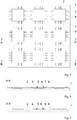
- FIG. 1 shows an embodiment of a substrate carrier according to the invention in a plan view.
- the substrate carrier has a substrate carrier plate 1 with a substrate carrier surface 2 on the front side.
- rectangular substrate receiving areas 3 are arranged at a distance from one another in a plurality of columns and rows.
- Each substrate receiving area 3 has a rectangular inner area 5 with a low height level and an outer area 6 running around the inner area 5.
- the substrate receiving area 3 and the inner area 5 have geometries other than rectangular, for example circular, oval or octagonal.
- plateaus 7 with a height level that is higher than that of the inner area 5 and ventilation channels 8 with the low height level of the inner area 5 are provided.
- the ventilation channels 8 are designed as parallel or perpendicular to each other aligned grooves and the plateaus 7 as parallel or perpendicular to each other aligned webs.
- the ventilation channels 8 can also be arranged at an acute or obtuse angle to one another.
- the plateaus 7 can form acute or obtuse angles to one another.
- Projections 9 protruding from the substrate carrier surface 2 are provided around the substrate receiving area 3.
- Exactly one projection 9 is provided on each side of the substrate receiving area 3, so that the rectangular substrate receiving area 3 is surrounded by four projections 9.
- a substrate 4 can be prevented from slipping in any direction.
- a plurality of projections 9 can be arranged on each side of the substrate receiving area 3.
- the projections 9 are in the embodiment of FIG Figure 1 arranged on plateaus 7.
- the projections 9 can be arranged in ventilation channels 8, the ventilation channels 8 then being made wider than the projections 9 so that a gas flow through the ventilation channels 8 is not impeded.
- Figure 2 shows the substrate carrier Figure 1 in a plan view of the front substrate carrier surface 2 with substrates 4 resting on the substrate carrier plate 1.
- the substrates 4 here rest on the substrate receiving areas 3 and cover them.
- the substrates 4 are rectangular in the embodiment shown here, but can alternatively also have round or other, for example polygonal, geometries, for example.
- the projections 9 are arranged laterally spaced from the substrates 4. A small distance is provided between the substrates 4 and the projections 9, so that a substrate 4 can be arranged between four projections 9 surrounding the substrate 4. On the other hand, this distance between the substrate 4 and the projections 9 is selected to be so small that the substrate 4 is limited by one of the projections 9 in the event of a slight horizontal displacement.
- the ventilation channels 8 are arranged laterally and in an edge region of the substrates 4, each of which runs from an outer region 6 into an inner region 5 and is thus partially arranged under the respective substrate 4.
- a plateau 7 is arranged in each case between two ventilation channels 8, the substrate 4 resting on the plateaus 7, the plateaus 7 in FIG Figure 2 can only be seen as areas between the ventilation channels 8.
- FIG. 13 is a cross section of a substrate carrier according to the invention with substrates 4 resting thereon along the line AA from FIG Figure 2 shown, that is, along the plateaus 7.
- the substrates 4 rest on the substrate carrier surface 2 of the substrate carrier plate 1 on the front side. Laterally spaced from the substrates 4, a plurality of projections 9 are arranged at a small distance from the respective substrate 4.
- the substrate 4 rests in an outer region 6 on at least one plateau 7, whereas in the inner region 5 arranged below the substrate 4 there is a free space or cavity between the substrate 4 and the substrate carrier plate 1.
- FIG. 14 is a cross section of a substrate carrier according to the invention with substrates 4 resting thereon along the line BB from FIG Figure 2 shown, so along the ventilation channels 8.
- the ventilation channel 8 running under the substrate 4 can be seen in the outer area 6.
- the ventilation channel 8 is located at the same level as the inner area 5 and connects it fluidically to a space above and around the substrate carrier plate 1. If a substrate carrier plate 1 with substrates 4 placed thereon is vented for a vacuum process, the gas located in the cavity located in the inner area 5 between the substrate carrier plate 1 and the substrate 4 can be conducted to the outside through the ventilation channels 8. In the case of ventilation after a vacuum process, the gas can again flow through the ventilation channels 8 into the inner region 5 and thus ventilate the substrate 4 from behind.
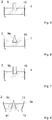
- FIG 5 is shown schematically in cross section a detailed view of a protrusion 9 designed as a pin of a substrate carrier according to the invention in a blind hole 10.
- the blind hole 10 is made in the front substrate carrier surface 2 of the substrate carrier plate 1, the blind hole 10 representing a recess in the front substrate carrier surface 2 which does not pass through the substrate carrier plate 1.
- the blind hole 10 can be designed as a round recess, that is to say in the form of a cylinder, but alternatively it can also have an angular or oval base area.
- the base area of the projection 9 is preferably congruent to the base area of the blind hole 10, but is designed to be smaller so that the projection 9 can be inserted into the blind hole 10 without friction.
- the pin-shaped projection 9 is thus designed as a cylinder.
- the projection 9 is made from a block and designed as a straight body.
- FIG 6 is shown schematically in cross section a detailed view of a projection 9a that can be used instead of the projection 9 in an embodiment of the substrate carrier according to the invention.
- the projection 9a is designed as a body tapering towards the top, ie in the case of a round base area as a cone and in the case of an angular base area as a pyramid.
- the sunk base of the projection 9a is designed as a straight body and only a region of the projection 9a that is raised above the blind hole is formed as a tapering body.
- the projection 9a is formed from one block.
- FIG 7 is shown schematically in cross section a detailed view of a further alternative embodiment of a projection 9b that can be used instead of the projection 9 or 9a in the substrate carrier according to the invention.
- the projection 9b is hollow on the inside, that is to say it can be a cylinder tube or a prism which is hollow on the inside. This has the advantage, in particular in a vacuum process, that when ventilation occurs, the projection 9b is not pulled out of the blind hole 10 due to the negative pressure created above the substrate carrier surface 2 on the front side.
- FIG 8 an alternative embodiment of a substrate carrier according to the invention is shown schematically in cross section, in which the substrate carrier plate 1 a has a through opening 13.
- a projection 9c extends from a rear side 12 of the substrate carrier to the substrate carrier surface 2 on the front side through the opening 13.
- Both the opening 13 and the projection 9c are tapered in the direction of the front substrate carrier surface 2, the opening 13 and the projection 9c in the embodiment shown have the same circumference on the front substrate carrier surface 2, so there is a stop at this point , whereby the projection 9c can no longer protrude through the opening 13.
- a fixing element 91 is arranged on the projection 9c, which can be connected to the rear side 12 in a fixed and gas-tight manner, for example by soldering. This prevents the projection 9c from falling out of the substrate carrier plate 1a.
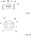
- FIG. 9 a further alternative embodiment of a substrate carrier according to the invention with the substrate carrier plate 1b is shown schematically in cross section.
- the substrate carrier plate 1b has a groove 14 in the substrate carrier surface 2 on the front side, which groove is widened in a recessed area compared to an area close to the substrate carrier surface 2.
- the projection 9d arranged in the groove 14 is designed to match the shape of the groove 14, that is to say has a widening in a lower region which forms the holding element 92.
- the holding element 92 is encompassed by the counter-holding element 15, which passes through the groove 14 in the substrate carrier plate 1b is formed. This prevents the projection 9d from being pulled vertically out of the groove 14 by means of a form fit.
- the projection 9d can be secured against horizontal slipping in the groove 14 by at least one stop element which can be fixed in the groove 14 next to the projection 9d.
- FIG 10 an alternative embodiment of a receiving area 3a is shown in a top view.
- Four rectangularly shaped support structures 11 are arranged in the inner area 5a, which can form the same level as the plateaus 7.
- the support structures 11 can come into contact with a substrate 4, which can be placed on the substrate receiving area 3a.
- this prevents the substrate 4 from bending over the inner region 3a.
- a contact surface between the substrate 4 and the substrate carrier plate 1 is thus obtained in comparison with the embodiment according to FIG Figure 1 enlarged, whereby the heat transfer between the substrate carrier plate 1 and the substrate 4 is increased.
Landscapes
- Chemical & Material Sciences (AREA)
- General Chemical & Material Sciences (AREA)
- Chemical Kinetics & Catalysis (AREA)
- Engineering & Computer Science (AREA)
- Materials Engineering (AREA)
- Mechanical Engineering (AREA)
- Metallurgy (AREA)
- Organic Chemistry (AREA)
- Container, Conveyance, Adherence, Positioning, Of Wafer (AREA)
- Packaging Of Annular Or Rod-Shaped Articles, Wearing Apparel, Cassettes, Or The Like (AREA)
- Physical Vapour Deposition (AREA)
- Laminated Bodies (AREA)
Description
- Die vorliegende Erfindung betrifft einen Substratträger mit einer Substratträgerplatte, die eine vorderseitige Substratträgeroberfläche aufweist, auf der wenigstens ein Substrataufnahmebereich zur Aufnahme jeweils eines Substrates vorgesehen ist.
- Substratträger, die bei der Bearbeitung von insbesondere Halbleitersubstraten, wie beispielsweise Siliziumwafern, zum Einsatz kommen, sollen wenigstens ein Substrat sicher halten und dessen bzw. deren einwandfreie Bearbeitung ermöglichen. Typischerweise kommen hierbei horizontal ausgerichtete Substratträger, sogenannte Trays oder Carrier, zum Einsatz, auf deren Oberfläche wenigstens ein flächiges Substrat, wie beispielsweise ein Halbleiterwafer, abgelegt und in dieser Stellung bearbeitet und/oder auf dem Substratträger transportiert wird. Das oder die Substrat(e) soll(en) dabei stabil auf dem Substratträger aufliegen. Nach erfolgter Bearbeitung bzw. nach erfolgtem Transport soll(en) das oder die Substrat(e) wieder schädigungsfrei von dem Substratträger genommen werden können.
- Ein Substratträger der eingangs genannten Art ist beispielsweise aus der Druckschrift
DE 40 26 244 C2 bekannt. Der bekannte Substratträger weist eine Substratträgerplatte mit einer Vertiefung auf, in der ein Substrat flächig aufliegt. Die Seitenwände der Vertiefung halten das Substrat in seiner Position. Für eine Vakuumfixierung des Substrates auf dem Substratträger sowie eine mögliche Belüftung nach einem Vakuumvorgang sind nach diesem Stand der Technik ein umlaufender Freiraum zwischen dem Substrat und dem Substratträger sowie eine unterhalb des Substrates angebrachte, durch den Substratträger hindurch reichende Bohrung vorgesehen. Das heißt, das Substrat liegt mittig auf einer Art Podest auf dem Substratträger auf, während die äußeren Bereiche des Substrates den Substratträger nicht berühren, da der Substratträger an diesen Bereichen vertieft ist. Außerdem kann sich mittig unter dem Substrat ein weiterer Freiraum befinden, wobei die Substratträgerplatte in diesem zentralen Bereich eine durchgehende Öffnung aufweist. Nachteilig an diesem Stand der Technik ist, dass sich das Podest insbesondere bei einem Plasmaprozess auf dem Substrat abbilden kann, wodurch die Eigenschaften des Substrates, beispielsweise die elektrische Leitfähigkeit, negativ beeinflusst werden können. Außerdem kann das Substrat in die umlaufende Vertiefung hinein kippen und liegt dann somit nicht mehr plan auf dem Substratträger auf. Dadurch können beispielsweise Beschädigungen des Substrates hervorgerufen werden und/oder Inhomogenitäten bei der Substratbearbeitung, wie beispielsweise eine inhomogene Substratbeschichtung, auftreten. - Die Druckschrift
US 2007/0026148 A1 offenbart einen Substratträger, der aus einem flachen Ring mit voneinander beabstandeten ersten und zweiten Substratauflagestegen ausgebildet ist. Der Ring weist eine äußere, höhere Stufe und eine innere, niedrigere Stufe auf. Die ersten und die zweiten Substratauflagebereiche erstrecken sich strahlenförmig als erhabene Bereiche auf der inneren, niedrigeren Stufe. Während sich die Oberflächen der ersten Substratauflagebereiche auf dem gleichen Höhenniveau wie die Oberfläche der äußeren, höheren Stufe des Rings befinden, liegen die Oberflächen der zweiten Substratauflagebereiche zwar auf einem niedrigeren Höhenniveau als die äußere, höhere Stufe, aber auf einem höheren Höhenniveau als die innere, niedrigere Stufe des Rings. - In der Druckschrift
DE 10 2009 021 563 A1 ist ein sich in einer Schleuse befindlicher Substratträger beschrieben. In den Substratträger sind Aussparungen eingebracht, in welchen jeweils ein Substrat liegt. Die Substrate werden durch einen auf deren Oberflächen gerichteten Gasstrom gegen den Substratträger gedrückt. - Aus der Druckschrift
DE 10 2014 100 024 A1 geht ein Substratträger mit in einer Horizontalfläche angeordneten Lagerplätzen für jeweils ein kreisscheibenförmiges Substrat hervor, wobei sich zwischen den Lagerplätzen räumlich voneinander getrennte und Zentrierflanken aufweisende Sockel befinden, an welchen jeweils Anlagestellen zur berührenden Anlage eines Abschnittes des Randes eines Substrates ausgebildet sind. -
US 2010/0089314A1 offenbart einen Substratträger mit einer Substratträgerplatte, die eine vorderseitige Substratträgeroberfläche aufweist, auf der ein Substrataufnahmebereich zur Aufnahme eines Substrates vorgesehen ist, wobei der Substrataufnahmebereich einen Innenbereich und einen um den Innenbereich verlaufenden Außenbereich aufweist, wobei der Außenbereich voneinander beabstandete, gegenüber einer Oberfläche des Innenbereichs erhabene Plateaus zur Auflage von Randbereichen des Substrates aufweist, wobei zwischen den Plateaus Belüftungskanäle vorgesehen sind. Die Belüftungskanäle liegen dabei als parallel zueinander ausgerichtete Rillen vor. - Es ist daher die Aufgabe der vorliegenden Erfindung, einen Substratträger vorzuschlagen, der möglichst ohne Beeinträchtigung der Eigenschaften des Substrates oder der Substratbearbeitung eine sichere Auflage des Substrates und bei einem schnellen Handling eine einfache, zerstörungsfreie Entnahme des Substrates von dem Substratträger gewährleistet.
- Die Aufgabe wird erfindungsgemäß durch einen Substratträger mit einer Substratträgerplatte, die eine vorderseitige Substratträgeroberfläche aufweist, auf der wenigstens ein Substrataufnahmebereich zur Aufnahme jeweils eines Substrates vorgesehen ist, gelöst, wobei der Substrataufnahmebereich einen Innenbereich und einen um den Innenbereich verlaufenden Außenbereich aufweist, wobei der Außenbereich voneinander beabstandete, gegenüber einer Oberfläche des Innenbereichs erhabene Plateaus zur Auflage von Randbereichen des Substrates aufweist, wobei zwischen den Plateaus Belüftungskanäle vorgesehen sind, und wobei die Belüftungskanäle als parallel oder senkrecht zueinander ausgerichtete Rillen und die Plateaus als parallel oder senkrecht zueinander ausgerichtete Stege ausgebildet sind und sich die Belüftungskanäle auf dem gleichen Höhenniveau wie der Innenbereich befinden und diesen fluidisch mit einem über und um der/die Substratträgerplatte vorhandenen Raum verbinden.
- Bei dem erfindungsgemäßen Substratträger sind in der vorderseitigen Substratträgeroberfläche mehrere, voneinander durch Unterbrechungen getrennte Auflageabschnitte vorgesehen, die sich zumindest teilweise unterhalb eines auf dem Substratträger vorgesehenen Substrates befinden und einen Auflagebereich für einen Randbereich eines auf den Substratträger abzulegenden Substrates ausbilden. Somit liegt das Substrat randseitig auf einem erhabenen Niveau gegenüber dem Innenbereich des Substrataufnahmebereiches auf der Substratträgerplatte auf. Zwischen den voneinander beabstandeten Plateaus sowie in dem Innenbereich des Substrataufnahmebereiches weist die vorderseitige Substratträgeroberfläche ein niedrigeres Niveau als auf den Plateaus auf. Dabei sind zwischen den Plateaus Kanäle ausgebildet, welche bei einer Be- und/oder Entlüftung als Belüftungskanäle wirken, also Gas in den Innenbereich des Substrataufnahmebereiches leiten können und somit eine Hinterlüftung des Substrates ermöglichen, was wiederum eine einfache, zerstörungsfreie Entnahme des Substrates von dem Substratträger ermöglicht.
- Der erfindungsgemäße Substratträger bietet somit den Vorteil, dass das Substrat mit seinen Randbereichen auf dem Substrataufnahmebereich zügig planparallel ablegbar ist und sich dabei kein Gaspolster zwischen dem Substrat und den Auflageabschnitten ausbilden kann, wodurch ein horizontales Verrutschen des Substrates auf dem Substratträger weitgehend vermieden wird. Dabei befindet sich in dem Innenbereich des Substrataufnahmebereiches wenigstens ein Freiraum zwischen dem Substratträger und dem Substrat. Das in diesem Freiraum befindliche Gas kann über die zwischen den Plateaus befindlichen Belüftungskanäle bei der Substratauflage nach außen hin entweichen, sodass das Substrat nicht auf dem Außenbereich "aufschwimmt". Dies erleichtert die sichere und zügige Ablage des Substrates auf der Substratträgerplatte, da ein Verrutschen des Substrates auf einem Gaspolster vermieden wird.
- Die Belüftungskanäle bewirken zudem bei einer Entnahme des Substrates von dem Substratträger, dass seitlich Gas unter das Substrat geführt wird und dadurch das Substrat leicht und zerstörungsfrei von der Substratträgerplatte abgehoben werden kann. Weiterhin sind die Plateaus und Belüftungskanäle nur in einem Randbereich des Substrates vorgesehen, sodass eine Abbildung dieser Strukturen auf dem Substrat möglichst gering gehalten wird.
- In einer bevorzugten Ausführungsform des erfindungsgemäßen Substratträgers sind die Plateaus auf einem gleichen Niveau wie die vorderseitige Substratträgeroberfläche, ausgenommen einer Oberfläche des oder der Innenbereiche(s), ausgebildet. Das heißt, lediglich für den Innenbereich und die Belüftungskanäle ist ein anderes, nämlich niedrigeres, Niveau als für die übrige vorderseitige Substratträgeroberfläche vorgesehen. Die Plateaus können dadurch ausgebildet werden, dass sie Bereiche der vorderseitigen Substratträgeroberfläche zwischen den Belüftungskanälen darstellen. Dadurch ergibt sich eine günstige Fertigung des erfindungsgemäßen Substratträgers.
- In einer vorteilhaften Weiterbildung des erfindungsgemäßen Substratträgers sind die Belüftungskanäle allseitig um den Substrataufnahmebereich vorgesehen. Dadurch wird eine gleichmäßige Ent- und Belüftung einer Rückseite des Substrates ermöglicht. Das Luft- oder Gaspolster unter dem Substrat wird also bei der Substratträgerauflage gleichmäßig entfernt bzw. bei der Substratentnahme gleichmäßig wieder hergestellt, sodass das Substrat nicht nur sicher und plan auf dem Substratträger aufliegen, sondern auch sicher und schnell wieder von diesem entnommen werden kann.
- Besonders bevorzugt sind die Plateaus bei der vorliegenden Erfindung stegartig ausgebildet. Damit ergibt sich einerseits eine stabile Auflagemöglichkeit während andererseits die stegartigen Plateaus nur eine geringe Auflagefläche bilden und sich damit nur minimal bis gar nicht auf einer Rückseite des Substrates und/oder auf der Substatträgervorderseite bei der Substratbehandlung abbilden. Die Auflageabschnitte bildenden Plateaus sind also vorzugsweise länglich und/oder rechteckig geformt, wodurch eine einfache und preisgünstige Herstellung der Plateaus und/oder der Belüftungskanäle ermöglicht wird.
- Gemäß einer bevorzugten Ausführungsform des erfindungsgemäßen Substratträgers sind die Belüftungskanäle in die vorderseitige Substratträgeroberfläche eingefräst. Dadurch sind die Belüftungskanäle insbesondere einfach und kostengünstig fertigbar. Ebenso kann der Innenbereich, welcher gegenüber dem Außenbereich ein niedrigeres Höhenniveau aufweist, in die vorderseitige Substratträgeroberfläche eingefräst sein.
- In einer alternativen Ausführungsform der vorliegenden Erfindung ist in dem Innenbereich wenigstens eine Stützstruktur vorgesehen, auf der das Substrat zumindest teilweise aufliegen kann. Dadurch wird die Berührungsfläche zwischen dem Substrat und dem Substratträger effektiv erhöht, wodurch die Wärmeübertragung zwischen dem Substratträger und dem Substrat verbessert wird. Durch die Stützstruktur kann es jedoch zur Abbildung von deren Struktur auf dem Substrat, insbesondere auch auf einer Substratvorderseite, sowie in einem Plasmaprozess zu unerwünschten Beeinflussungen des Plasmas kommen.
- In einer geeigneten Ausführungsform des erfindungsgemäßen Substratträgers sind die Plateaus und/oder die Stützstruktur durch einen Materialauftrag auf die vorderseitige Substratträgeroberfläche aufgebracht. Möglichkeiten zum Aufbringen solcher plateauartiger Auflageabschnitte sowie der Stützstruktur sind beispielsweise 3D-Druck, (photo)lithographische Verfahren, Anschrauben, Verlöten, Anpunkten oder Schweißen. Außerdem können die Ausführungsformen der vorliegenden Erfindung, bei welchen Belüftungskanäle in die vorderseitige Substratträgeroberfläche eingefräst und die Plateaus durch Materialauftrag auf die vorderseitige Substratträgeroberfläche aufgebracht werden, auch miteinander kombiniert werden.
- In einer besonders vorteilhaften Weiterbildung des erfindungsgemäßen Substratträgers liegt eine Höhe der Plateaus und/oder eine Tiefe der Belüftungskanäle in einem Bereich von 0,1 mm bis 1 mm, bevorzugt in einem Bereich von 0,2 mm bis 0,5 mm. Mit der Höhe der Plateaus ist hierbei die Höhe gegenüber dem Innenbereich des Substratauflagebereiches und/oder die Höhe gegenüber einer tiefsten Stelle eines Belüftungskanals gemeint. Es hat sich herausgestellt, dass die Be- und Entlüftung in einem Tiefen- und/oder Höhenbereich von 0,1 mm bis 1 mm, bevorzugt von 0,2 mm bis 0,5 mm, für ein schnelles Handling des wenigstens einen Substrates zufriedenstellend verläuft. Andererseits soll zwischen dem Substrat und dem Substratträger eine gute thermische Anbindung vorliegen, was durch den Tiefen- und/oder Höhenbereich von 0,1 mm bis 1 mm, bevorzugt von 0,2 mm bis 0,5 mm, ebenfalls gewährleistet ist.
- Als besonders vorteilhaft hat sich bei einem erfindungsgemäßen Substratträger erwiesen, wenn ein Abstand der Plateaus zueinander und/oder eine Breite der Belüftungskanäle in einem Bereich von 0,1 mm bis 5 mm, bevorzugt in einem Bereich von 0,2 mm bis 1 mm, liegt. Mit dem Abstand der Plateaus zueinander ist hierbei der Abstand gemeint, welchen ein Plateau in dem Außenbereich des Substratauflagebereiches zu einem benachbarten Plateau aufweist, also der Abstand, welcher durch die Breite eines Belüftungskanals zwischen zwei Plateaus hervorgerufen wird. In diesem Abstands- und/oder Breitenbereich von 0,1 mm bis 5 mm, bevorzugt von 0,2 mm bis 1 mm, hat sich ein zufriedenstellender Gasfluss bei einem Ent- und/oder Belüftungsvorgang herausgestellt.
- In einer bevorzugten Ausführungsform des erfindungsgemäßen Substratträgers ist die Substratträgerplatte aus wenigstens einem elektrisch leitfähigen Material ausgebildet und/oder mit wenigstens einem elektrisch leitfähigen Material beschichtet. Dadurch kann die Substratträgerplatte in einer Substratbehandlungskammer beispielsweise als eine Elektrode ausgeführt werden. Dies ist insbesondere nützlich, wenn das wenigstens eine zu behandelnde Substrat auf ein bestimmtes elektrisches Potenzial eingestellt werden soll. Als elektrisch leitfähiges Material kommt beispielsweise ein Metall oder eine Legierung in Betracht, insbesondere Aluminium, Titan oder auch eine Legierung eines dieser Metalle. Weiterhin weisen elektrisch leitfähige Materialien auch eine gute Wärmeleitfähigkeit auf, was für die Substratträgerplatte eine gewünschte Eigenschaft darstellt, um so beispielsweise mit einer an einer Rückseite der Substratträgerplatte angeordneten Temperiervorrichtung das auf der vorderseitigen Substratträgeroberfläche der Substratträgerplatte angeordnete Substrat zu wärmen oder zu kühlen.
- Nach einer vorteilhaften Weiterbildung des erfindungsgemäßen Substratträgers beträgt der Außenbereich des Substrataufnahmebereiches höchstens ein Zehntel einer Oberfläche eines auf dem Substratträger vorgesehenen Substrates. Dadurch wird eine mögliche Beeinflussung des Substrates durch eine geometrische Abbildung des Außenbereiches auf dem Substrat in einem Bearbeitungsprozess möglichst gering gehalten.
- Besonders bevorzugt ist wenigstens eine aus der vorderseitigen Substratträgeroberfläche aufragende Auskragung zur seitlichen Begrenzung einer Substratauflagefläche auf dem Substrataufnahmebereich vorgesehen. Die Auskragung dient als seitlicher Halt für das Substrat. Damit kann das Substrat also nicht horizontal verrutschen, beispielsweise im belüfteten Zustand, und ist in seiner Position auf dem Substrataufnahmebereich festgelegt. Vorteilhafterweise sind um einen Substrataufnahmebereich mehrere Auskragungen vorgesehen, sodass das Verrutschen eines Substrates in alle Richtungen unterbunden wird. Außerdem kann zwischen benachbarten Substraten jeweils genau eine Auskragung vorgesehen sein, sodass sich benachbarte Substrate jeweils eine Auskragung "teilen". Es können zwischen benachbarten Substraten alternativ aber auch voneinander beabstandete Auskragungen vorgesehen sein, sodass jede Auskragung jeweils nur einem Substrat benachbart ist.
- In einer alternativen Ausführungsform der vorliegenden Erfindung kann die Auskragung als wenigstens eine um den Substrataufnahmebereich verlaufende Stufe in der vorderseitigen Substratträgeroberfläche ausgebildet sein. Diese Stufe weist ein höheres Niveau auf als die Plateaus des Außenbereiches, wodurch ein sogenanntes Substratnest gebildet wird. Durch die Stufe verlaufen Belüftungskanäle, welche beispielsweise mit den Belüftungskanälen des Außenbereichs verbunden sein können. Somit wird das Substrat nicht vollumfänglich von der Stufe dicht anliegend umgeben und es kann eine effektive Be- und Entlüftung des Substrataufnahmebereiches gewährleistet werden.
- In einer vorteilhaften Weiterbildung des erfindungsgemäßen Substratträgers ist die wenigstens eine Auskragung ein Stift. Mit Stift ist hierbei ein zylindrischer Körper gemeint, dessen Mantelfläche sich senkrecht zu der vorderseitigen Substratträgeroberfläche erstreckt. Eine geläufige Bezeichnung für einen solchen Stift ist "Pin". Derartige zylindrische Körper sind insbesondere günstig herstellbar. In alternativen Ausführungsformen kann der Stift auch als vielseitiges Prisma ausgebildet sein, beispielsweise als dreiseitiges Prisma, Quader oder ein achtseitiges Prisma, wobei sich jeweils eine Mantelfläche des Prismas entlang einer länglichen Erstreckung des Prismas senkrecht zu der vorderseitigen Substratträgeroberfläche erstreckt.
- Vorzugsweise ist die Auskragung in eine in die vorderseitige Substratträgeroberfläche eingebrachte Sacklochbohrung eingesetzt. Eine Sacklochbohrung stellt eine Ausnehmung in der Substratträgeroberfläche dar, welche die Substratträgerplatte nicht durchgreift. Die Auskragung wird in die Sacklochbohrung eingesteckt, also versinkt sie zu einem Teil in der Bohrung und lediglich ein Teil der Auskragung kragt aus der Bohrung heraus, um das Substrat an einem seitlichen Verrutschen zu hindern. Die Auskragung steckt also lose in der Sacklochbohrung. Alternativ kann die Auskragung auch formschlüssig in der Sacklochbohrung gehalten werden, beispielsweise durch einen Bajonettverschluss oder gegeneinander keilartig verlaufende Oberflächen der Sacklochbohrung und der Auskragung. Dadurch kann die Auskragung fest, aber lösbar, mit der Substratträgerplatte verbunden sein. In einem Spezialfall kann die Auskragung als Schraube und die Sacklochbohrung mit einem Gewinde versehen ausgebildet sein, sodass die Auskragung in die vorderseitige Substratträgeroberfläche einschraubbar ausgebildet ist.
- In einer besonderen Ausgestaltung der vorliegenden Erfindung ist die Auskragung von einer Rückseite des Substratträgers eingebracht, wobei die Auskragung aus einer Öffnung der vorderseitigen Substratträgeroberfläche herausragt, wobei die Auskragung in der Öffnung durch die Größe der Öffnung gehalten wird und wobei die Auskragung mit einem Fixierelement von der Rückseite in der Öffnung fixiert ist. In dieser Variante ist also eine durch die Substratträgerplatte hindurchgehende Öffnung vorgesehen, durch welche die Auskragung von der Rückseite des Substratträgers hindurch reichen kann. Die Öffnung und die Auskragung können dabei so ausgeformt sein, dass in Richtung der vorderseitigen Substratträgeroberfläche eine Art Anschlag besteht, die Auskragung also nur bis zu einem bestimmten Punkt durch die Öffnung hindurch reichen kann. An der Rückseite des Substratträgers und somit an der Rückseite der Öffnung ist die Auskragung an dem Substratträger durch das Fixierelement befestigt. Die Befestigung kann insbesondere gasdicht gestaltet sein, sodass die Fixierung der Auskragung die Öffnung im Substratträger abdichtet.
- Gemäß einer weiteren Alternative der vorliegenden Erfindung ist die Auskragung in einer in der Substratträgerplatte parallel zur vorderseitigen Substratträgeroberfläche verlaufenden Nut angeordnet, wobei ein in der Nut befindliches Halteelement der Auskragung von einem Gegenhalteelement der Nut umgriffen wird. Die Nut kann also in einem tiefen Bereich breiter ausgeführt sein als in einem Bereich nahe der vorderseitigen Substratträgeroberfläche, sodass eine Verjüngung der Nut in Richtung der vorderseitigen Substratträgeroberfläche vorliegt. Der verjüngte Bereich kann das Gegenhalteelement ausbilden. Die Auskragung kann ihrerseits an einem untersten, in der Nut vorgesehenen Bereich verbreitert sein, ähnlich einem Schraubenkopf. Dieser verbreiterte Bereich der Auskragung kann das Halteelement ausbilden. Dadurch wird die Auskragung durch Formschluss in der Nut gehalten. Im Falle einer länglichen Nut kann die Auskragung, wie ein so genannter Nutenstein, in eine gewünschte Position verschoben werden und ein- oder beidseitig durch wenigstens ein Stoppelement in der gewünschten Position gegen ein Verrutschen gesichert werden.
- In einer bevorzugten Ausführungsform des erfindungsgemäßen Substratträgers ist die Auskragung aus wenigstens einem elektrischen Isolator ausgebildet. Elektrische Isolatoren sind schlechte Wärmeleiter, wodurch die Ausbildung einer Wärmesenke durch den Stift als Auskragung vermieden wird. Außerdem kann die Substratträgerplatte in einem Substratbehandlungsprozess als Elektrode verwendet werden. Durch die Ausführung der Auskragung als elektrischer Isolator wird vermieden, dass sich Potenzialspitzen über der Substratträgerplatte aufbauen. Wird das Substrat beispielsweise in einem Plasma behandelt, wird also eine Verzerrung des Plasmas vermieden, indem die Auskragung als elektrischer Isolator ausgebildet ist. Als Material für die Auskragung kommt beispielsweise Glas, Quarz, Keramik oder Kunststoff in Betracht, insbesondere Aluminiumoxid. Daher können solche Auskragungen auch als "Keramik-Pins" bezeichnet werden.
- Gemäß einer vorteilhaften Weiterbildung des erfindungsgemäßen Substratträgers ist die Auskragung innen hohl ausgebildet. Die Auskragung kann also beispielsweise ein Hohlzylinder sein. Dies ist günstig für einen Substratbehandlungsprozess im Vakuum, da die Auskragung beim Entlüften so nicht aus der Sacklochbohrung durch den entstehenden Unterdruck herausgezogen werden kann.
- Als vorteilhaft hat sich außerdem herausgestellt, wenn die Auskragung an einem von der Substratträgerplatte weg zeigenden Ende spitz oder verrundet zulaufend ausgebildet ist. Sollte also ein Substrat auf der vorderseitigen Substratträgeroberfläche fehlerhafterweise außerhalb des Substrataufnahmebereiches abgelegt werden, sodass das Substrat eine geneigte Oberfläche der Auskragung berührt, führt diese geneigte Oberfläche der Auskragung zu einer Richtungsweisung des Substrates hin zum Substrataufnahmebereich. Dadurch wird also bewirkt, dass die Substrate zwischen den Auskragungen angeordnet werden.
- Vorteilhafte Ausführungsformen der vorliegenden Erfindung, deren Aufbau, Funktion und Vorteile sind im Folgenden anhand von Figuren näher erläutert, wobei
- Figur 1
- schematisch eine Draufsicht auf eine vorderseitige Substratträgeroberfläche eines erfindungsgemäßen Substratträgers zeigt;
- Figur 2
- schematisch eine Draufsicht auf die vorderseitige Substratträgeroberfläche des Substratträgers aus
Figur 1 mit auf Substrataufnahmebereichen des Substratträgers abgelegten Substraten zeigt; - Figur 3
- schematisch eine Querschnittansicht eines erfindungsgemäßen Substratträgers mit darauf abgelegten Substraten entlang von Plateaus von Substrataufnahmebereichen des Substratträgers zeigt;
- Figur 4
- schematisch eine weitere Querschnittsansicht des erfindungsgemäßen Substratträgers aus
Figur 3 mit darauf abgelegten Substraten entlang von Belüftungskanälen zeigt; - Figur 5
- eine Detailansicht eines erfindungsgemäßen Substratträgers mit einer zylinder- oder quaderförmigen Auskragung in einer Sacklochbohrung in einer Querschnittsdarstellung zeigt;
- Figur 6
- eine Detailansicht eines erfindungsgemäßen Substratträgers mit einer pyramiden- oder kegelförmigen Auskragung in einer Sacklochbohrung in einer Querschnittsdarstellung zeigt;
- Figur 7
- eine Detailansicht eines erfindungsgemäßen Substratträgers mit einer innen hohl ausgebildeten Auskragung in einer Sacklochbohrung in einer Querschnittsdarstellung zeigt;
- Figur 8
- eine Detailansicht einer alternativen Ausführungsform eines erfindungsgemäßen Substratträgers mit einer durch eine Öffnung des Substratträgers hindurch reichenden Auskragung in einer Querschnittsdarstellung zeigt;
- Figur 9
- eine Detailansicht einer weiteren alternativen Ausführungsform eines erfindungsgemäßen Substratträgers mit einer in einer Nut gehaltenen Auskragung in einer Querschnittsdarstellung zeigt; und
- Figur 10
- schematisch eine Draufsicht auf einen Substrataufnahmebereich eines erfindungsgemäßen Substratträgers mit in dem Innenbereich angeordneten Stützstrukturen zeigt.
-
Figur 1 zeigt eine Ausführungsform eines erfindungsgemäßen Substratträgers in einer Draufsicht. Der Substratträger weist eine Substratträgerplatte 1 mit einer vorderseitigen Substratträgeroberfläche 2 auf. Auf der Substratträgeroberfläche 2 sind in mehreren Spalten und Reihen rechteckige Substrataufnahmebereiche 3 voneinander beabstandet angeordnet. Jeder Substrataufnahmebereich 3 weist jeweils einen rechteckigen Innenbereich 5 mit einem niedrigen Höhenniveau sowie einen um den Innenbereich 5 verlaufenden Außenbereich 6 auf. Alternativ ist auch vorstellbar, dass der Substrataufnahmebereich 3 und der Innenbereich 5 andere Geometrien als rechteckig aufweisen, beispielsweise kreisförmig, oval oder achteckig. - In dem Außenbereich 6 sind Plateaus 7 mit einem gegenüber dem Innenbereich 5 erhöhten Höhenniveau sowie Belüftungskanäle 8 mit dem niedrigen Höhenniveau des Innenbereiches 5 vorgesehen. In der Ausführungsform in
Figur 1 sind die Belüftungskanäle 8 als parallel oder senkrecht zueinander ausgerichtete Rillen und die Plateaus 7 als parallel oder senkrecht zueinander ausgerichtete Stege ausgebildet. In anderen Ausführungsformen der vorliegenden Erfindung können die Belüftungskanäle 8 auch zueinander in einem spitzen oder stumpfen Winkel angeordnet sein. Ebenso können die Plateaus 7 zueinander spitze oder stumpfe Winkel bilden. - Um den Substrataufnahmebereich 3 sind aus der Substratträgeroberfläche 2 heraus ragende Auskragungen 9 vorgesehen. In der Ausführungsform in
Figur 1 ist je Seite des Substrataufnahmebereiches 3 genau eine Auskragung 9 vorgesehen, sodass der rechteckige Substrataufnahmebereich 3 von vier Auskragungen 9 umgeben ist. Dadurch kann ein Verrutschen eines Substrates 4 in jeder Richtung unterbunden werden. In alternativen Ausführungsformen können je Seite des Substrataufnahmebereiches 3 mehrere Auskragungen 9 angeordnet sein. Bei kreisförmigen oder ovalen Geometrien des Substrataufnahmebereiches 3 ist es vorteilhaft, die Auskragungen 9 ebenfalls kreisförmig oder oval um den Substrataufnahmebereich 3 anzuordnen. Die Auskragungen 9 sind in der Ausführungsform vonFigur 1 auf Plateaus 7 angeordnet. Alternativ können die Auskragungen 9 in Belüftungskanälen 8 angeordnet sein, wobei die Belüftungskanäle 8 dann breiter ausgebildet sind als die Auskragungen 9, damit ein Gasfluss durch die Belüftungskanäle 8 nicht behindert wird. -
Figur 2 zeigt den Substratträger ausFigur 1 in einer Draufsicht auf die vorderseitige Substratträgeroberfläche 2 mit auf der Substratträgerplatte 1 aufliegenden Substraten 4. Die Substrate 4 liegen hier auf den Substrataufnahmebereichen 3 auf und verdecken diese. Die Substrate 4 sind in der hier gezeigten Ausführungsform rechteckig ausgebildet, können alternativ aber beispielsweise auch runde oder andere, beispielsweise vieleckige Geometrien aufweisen. - Seitlich beabstandet zu den Substraten 4 sind die Auskragungen 9 angeordnet. Zwischen den Substraten 4 und den Auskragungen 9 ist ein geringer Abstand vorgesehen, sodass je ein Substrat 4 zwischen vier das Substrat 4 umgebenden Auskragungen 9 angeordnet werden kann. Andererseits ist dieser Abstand zwischen dem Substrat 4 und den Auskragungen 9 so gering gewählt, dass das Substrat 4 im Falle einer geringen horizontalen Verschiebung von einer der Auskragungen 9 begrenzt wird.
- Weiterhin sind seitlich und in einem Randbereich der Substrate 4 die Belüftungskanäle 8 angeordnet, welche jeweils von einem Außenbereich 6 in einen Innenbereich 5 verlaufen und somit teilweise unter dem jeweiligen Substrat 4 angeordnet sind. Zwischen zwei Belüftungskanälen 8 ist jeweils ein Plateau 7 angeordnet, wobei das Substrat 4 auf den Plateaus 7 aufliegt, wobei die Plateaus 7 in
Figur 2 lediglich als Bereiche zwischen den Belüftungskanälen 8 erkennbar sind. - In
Figur 3 ist ein Querschnitt eines erfindungsgemäßen Substratträgers mit darauf aufliegenden Substraten 4 gemäß der Linie A-A ausFigur 2 gezeigt, also entlang der Plateaus 7. Auf der vorderseitigen Substratträgeroberfläche 2 der Substratträgerplatte 1 liegen die Substrate 4 auf. Seitlich beabstandet zu den Substraten 4 sind jeweils mehrere Auskragungen 9 mit geringem Abstand zu dem jeweiligen Substrat 4 angeordnet. Das Substrat 4 liegt jeweils in einem Außenbereich 6 auf wenigstens einem Plateau 7 auf, wohingegen in dem unter dem Substrat 4 angeordneten Innenbereich 5 ein Frei- oder Hohlraum zwischen dem Substrat 4 und der Substratträgerplatte 1 vorliegt. - In
Figur 4 ist ein Querschnitt eines erfindungsgemäßen Substratträgers mit darauf aufliegenden Substraten 4 gemäß der Linie B-B ausFigur 2 gezeigt, also entlang der Belüftungskanäle 8. Im Unterschied zuFigur 3 ist hierbei im Außenbereich 6 der unter dem Substrat 4 verlaufende Belüftungskanal 8 zu sehen. Der Belüftungskanal 8 befindet sich auf dem gleichen Höhenniveau wie der Innenbereich 5 und verbindet diesen fluidisch mit einem über und um der Substratträgerplatte 1 vorhandenen Raum. Wird also für einen Vakuumprozess eine Substratträgerplatte 1 mit darauf abgelegten Substraten 4 entlüftet, kann das in dem in dem Innenbereich 5 angeordneten, zwischen der Substratträgerplatte 1 und dem Substrat 4 ausgebildeten Hohlraum befindliche Gas durch die Belüftungskanäle 8 nach außen geleitet werden. Im Falle einer Belüftung nach einem Vakuumprozess kann wiederum das Gas durch die Belüftungskanäle 8 in den Innenbereich 5 strömen und somit das Substrat 4 hinterlüften. - In
Figur 5 ist schematisch im Querschnitt eine Detailansicht einer als Stift ausgeführten Auskragung 9 eines erfindungsgemäßen Substratträgers in einer Sacklochbohrung 10 gezeigt. Die Sacklochbohrung 10 ist in die vorderseitige Substratträgeroberfläche 2 der Substratträgerplatte 1 eingebracht, wobei die Sacklochbohrung 10 eine Vertiefung in der vorderseitigen Substratträgeroberfläche 2 darstellt, welche nicht durch die Substratträgerplatte 1 hindurchgeht. Die Sacklochbohrung 10 kann als eine runde Ausnehmung ausgebildet sein, also in Form eines Zylinders, alternativ kann sie jedoch auch eine eckige oder ovale Grundfläche aufweisen. - Die Auskragung 9 ist in ihrer Grundfläche vorzugsweise der Grundfläche der Sacklochbohrung 10 kongruent, jedoch kleiner ausgebildet, sodass ein reibungsloses Einsetzen der Auskragung 9 in die Sacklochbohrung 10 ermöglicht ist. Im Falle einer runden Sacklochbohrung 10 ist die stiftförmige Auskragung 9 also als Zylinder ausgebildet. In der Ausführungsform nach
Figur 5 ist die Auskragung 9 aus einem Block und als gerader Körper ausgeführt. - In
Figur 6 ist schematisch im Querschnitt eine Detailansicht einer anstelle der Auskragung 9 in einer Ausführungsform des erfindungsgemäßen Substratträgers verwendbare Auskragung 9a gezeigt. Die Auskragung 9a ist als nach oben hin spitz zulaufender Körper ausgebildet, also im Falle einer runden Grundfläche als Kegel und im Falle einer eckigen Grundfläche als Pyramide. Alternativ ist auch vorstellbar, dass ein in der Sacklochbohrung 10 versenkter Sockel der Auskragung 9a als gerader Körper ausgebildet ist und nur ein über die Sacklochbohrung erhabener Bereich der Auskragung 9a als spitz zulaufender Körper ausgeformt ist. In der Ausführungsform vonFigur 6 ist die Auskragung 9a aus einem Block ausgebildet. - In
Figur 7 ist schematisch im Querschnitt eine Detailansicht einer weiteren alternativen Ausführungsform einer anstelle der Auskragung 9 oder 9a bei dem erfindungsgemäßen Substratträger einsetzbaren Auskragung 9b gezeigt. Die Auskragung 9b ist innen hohl ausgebildet, kann also ein Zylinderrohr oder ein innen hohles Prisma sein. Dies hat insbesondere in einem Vakuumprozess den Vorteil, dass bei einer Entlüftung die Auskragung 9b aufgrund des über der vorderseitigen Substratträgeroberfläche 2 entstehenden Unterdrucks nicht aus der Sacklochbohrung 10 hinausgezogen wird. - In
Figur 8 ist schematisch im Querschnitt eine alternative Ausführungsform eines erfindungsgemäßen Substratträgers gezeigt, in dem die Substratträgerplatte 1a eine durchgehende Öffnung 13 aufweist. Eine Auskragung 9c reicht von einer Rückseite 12 des Substratträgers bis zur vorderseitigen Substratträgeroberfläche 2 durch die Öffnung 13 hindurch. Sowohl die Öffnung 13 als auch die Auskragung 9c sind sich in Richtung der vorderseitigen Substratträgeroberfläche 2 hin verjüngend ausgebildet, wobei die Öffnung 13 und die Auskragung 9c in der gezeigten Ausführungsform an der vorderseitigen Substratträgeroberfläche 2 den gleichen Umfang aufweisen, an dieser Stelle also ein Anschlag vorliegt, wodurch die Auskragung 9c nicht weiter durch die Öffnung 13 hindurch ragen kann. An der Rückseite 12 des Substratträgers ist an der Auskragung 9c ein Fixierelement 91 angeordnet, welches beispielsweise durch Löten fest und gasdicht mit der Rückseite 12 verbunden sein kann. Dadurch wird ein Herausfallen der Auskragung 9c aus der Substratträgerplatte 1a verhindert. - In
Figur 9 ist schematisch im Querschnitt eine weitere alternative Ausführungsform eines erfindungsgemäßen Substratträgers mit der Substratträgerplatte 1b gezeigt. Die Substratträgerplatte 1b weist in der vorderseitigen Substratträgeroberfläche 2 eine Nut 14 auf, welche in einem versenkten Bereich verbreitert ist gegenüber einem der Substratträgeroberfläche 2 nahen Bereich. Die in der Nut 14 angeordnete Auskragung 9d ist formangepasst an die Nut 14 ausgebildet, weist also in einem unteren Bereich eine Verbreiterung auf, welche das Halteelement 92 ausbildet. Das Halteelement 92 wird von dem Gegenhaltelement 15 umgriffen, welches durch die Nut 14 in der Substratträgerplatte 1b ausgebildet wird. Dadurch wird ein vertikales Herausziehen der Auskragung 9d aus der Nut 14 durch Formschluss verhindert. Gegen ein horizontales Verrutschen in der Nut 14 kann die Auskragung 9d durch wenigstens ein Stoppelement gesichert sein, welches jeweils neben der Auskragung 9d in der Nut 14 fixiert werden kann. - In
Figur 10 ist eine alternative Ausführungsform eines Aufnahmebereiches 3a in einer Draufsicht gezeigt. Im Gegensatz zu der Ausführungsform gemäßFigur 1 sind im Innenbereich 5a vier jeweils rechteckig geformte Stützstrukturen 11 angeordnet, welche das gleiche Niveau ausbilden können wie die Plateaus 7. Somit können die Stützstrukturen 11 mit einem Substrat 4, welches auf dem Substrataufnahmebereich 3a abgelegt werden kann, in Berührung kommen. Dadurch wird einerseits ein Durchbiegen des Substrates 4 über dem Innenbereich 3a vermieden. Außerdem wird so eine Berührungsfläche zwischen dem Substrat 4 und der Substratträgerplatte 1 im Vergleich zu der Ausführungsform gemäßFigur 1 vergrößert, wodurch die Wärmeübertragung zwischen der Substratträgerplatte 1 und dem Substrat 4 vergrößert wird.
Claims (15)
- Substratträger mit einer Substratträgerplatte (1, 1a, 1b), die eine vorderseitige Substratträgeroberfläche (2) aufweist, auf der wenigstens ein Substrataufnahmebereich (3, 3a) zur Aufnahme jeweils eines Substrates (4) vorgesehen ist, wobei der Substrataufnahmebereich (3, 3a) einen Innenbereich (5) und einen um den Innenbereich (5) verlaufenden Außenbereich (6) aufweist, wobei der Außenbereich (6) voneinander beabstandete, gegenüber einer Oberfläche des Innenbereichs (5) erhabene Plateaus (7) zur Auflage von Randbereichen des Substrates (4) aufweist, wobei zwischen den Plateaus (7) Belüftungskanäle (8) vorgesehen sind, dadurch gekennzeichnet, dass die Belüftungskanäle (8) als parallel oder senkrecht zueinander ausgerichtete Rillen und die Plateaus (7) als parallel oder senkrecht zueinander ausgerichtete Stege ausgebildet sind und sich die Belüftungskanäle (8) auf dem gleichen Höhenniveau wie der Innenbereich (5) befinden und diesen fluidisch mit einem über und um der/die Substratträgerplatte (1, 1a, 1b) vorhandenen Raum verbinden.
- Substratträger nach Anspruch 1, dadurch gekennzeichnet, dass die Plateaus (7) auf einem gleichen Niveau wie die vorderseitige Substratträgeroberfläche (2), ausgenommen einer Oberfläche des oder der Innenbereiche(s) (5), ausgebildet sind.
- Substratträger nach Anspruch 1 oder 2, dadurch gekennzeichnet, dass die Belüftungskanäle (8) allseitig um den Substrataufnahmebereich (3a) vorgesehen sind.
- Substratträger nach wenigstens einem der vorhergehenden Ansprüche, dadurch gekennzeichnet, dass die Belüftungskanäle (8) in die vorderseitige Substratträgeroberfläche (2) eingefräst sind.
- Substratträger nach wenigstens einem der vorhergehenden Ansprüche, dadurch gekennzeichnet, dass in dem Innenbereich (5) wenigstens eine Stützstruktur (11) vorgesehen ist, auf der das Substrat (4) zumindest teilweise aufliegen kann.
- Substratträger nach wenigstens einem der vorhergehenden Ansprüche, dadurch gekennzeichnet, dass die Plateaus (7) durch einen Materialauftrag auf die vorderseitige Substratträgeroberfläche (2) aufgebracht sind.
- Substratträger nach wenigstens einem der vorhergehenden Ansprüche, dadurch gekennzeichnet, dass die Substratträgerplatte (1, 1a, 1b) aus wenigstens einem elektrisch leitfähigem Material ausgebildet und/oder mit wenigstens einem elektrisch leitfähigen Material beschichtet ist.
- Substratträger nach wenigstens einem der vorhergehenden Ansprüche, dadurch gekennzeichnet, dass wenigstens eine aus der vorderseitigen Substratträgeroberfläche (2) aufragende Auskragung (9, 9a, 9b, 9c, 9d) zur seitlichen Begrenzung einer Substratauflagefläche auf dem Substrataufnahmebereich (3) vorgesehen ist.
- Substratträger nach Anspruch 8, dadurch gekennzeichnet, dass die wenigstens eine Auskragung (9, 9a, 9b, 9c, 9d) ein Stift ist.
- Substratträger nach Anspruch 8 oder 9, dadurch gekennzeichnet, dass die Auskragung (9, 9a, 9b, 9c, 9d) in eine in die vorderseitige Substratträgeroberfläche (2) eingebrachte Sacklochbohrung (10) eingesetzt ist.
- Substratträger nach Anspruch 8 oder 9, dadurch gekennzeichnet, dass die Auskragung (9, 9a, 9b, 9c, 9d) von einer Rückseite (12) des Substratträgers eingebracht ist, wobei die Auskragung (9, 9a, 9b, 9c, 9d) aus einer Öffnung (13) der vorderseitigen Substratträgeroberfläche (2) herausragt, wobei die Auskragung (9, 9a, 9b, 9c, 9d) in der Öffnung (13) durch die Größe der Öffnung (13) gehalten wird und wobei die Auskragung (9, 9a, 9b, 9c, 9d) mit einem Fixierelement (91) von der Rückseite (12) in der Öffnung (13) fixiert ist.
- Substratträger nach Anspruch 8 oder 9, dadurch gekennzeichnet, dass die Auskragung (9, 9a, 9b, 9c, 9d) in einer in der Substratträgerplatte (1) parallel zur vorderseitigen Substratträgeroberfläche (2) verlaufenden Nut (14) angeordnet ist, wobei ein in der Nut (14) befindliches Halteelement (92) der Auskragung (9, 9a, 9b, 9c, 9d) von einem Gegenhalteelement (15) der Nut (14) umgriffen wird.
- Substratträger nach wenigstens einem der Ansprüche 8 bis 12, dadurch gekennzeichnet, dass die Auskragung (9, 9a, 9b, 9c, 9d) aus wenigstens einem elektrischen Isolator ausgebildet ist.
- Substratträger nach wenigstens einem der Ansprüche 8 bis 13, dadurch gekennzeichnet, dass die Auskragung (9, 9a, 9b, 9c, 9d) innen hohl ausgebildet ist.
- Substratträger nach wenigstens einem der Ansprüche 8 bis 14, dadurch gekennzeichnet, dass die Auskragung (9, 9a, 9b, 9c, 9d) an einem von der Substratträgerplatte (1) weg zeigenden Ende spitz oder verrundet zulaufend ausgebildet ist.
Applications Claiming Priority (2)
| Application Number | Priority Date | Filing Date | Title |
|---|---|---|---|
| DE102015113956.1A DE102015113956B4 (de) | 2015-08-24 | 2015-08-24 | Substratträger |
| PCT/IB2016/054630 WO2017033076A1 (de) | 2015-08-24 | 2016-08-02 | Substratträger |
Publications (2)
| Publication Number | Publication Date |
|---|---|
| EP3178109A1 EP3178109A1 (de) | 2017-06-14 |
| EP3178109B1 true EP3178109B1 (de) | 2021-12-01 |
Family
ID=56738139
Family Applications (1)
| Application Number | Title | Priority Date | Filing Date |
|---|---|---|---|
| EP16753705.9A Active EP3178109B1 (de) | 2015-08-24 | 2016-08-02 | Substratträger |
Country Status (11)
| Country | Link |
|---|---|
| US (1) | US10964568B2 (de) |
| EP (1) | EP3178109B1 (de) |
| KR (1) | KR20180044375A (de) |
| CN (1) | CN108140607B (de) |
| DE (1) | DE102015113956B4 (de) |
| EA (1) | EA032316B9 (de) |
| HU (1) | HUE057728T2 (de) |
| MY (1) | MY194334A (de) |
| SG (1) | SG11201801454QA (de) |
| TW (1) | TWI715602B (de) |
| WO (1) | WO2017033076A1 (de) |
Families Citing this family (4)
| Publication number | Priority date | Publication date | Assignee | Title |
|---|---|---|---|---|
| DE102016115614A1 (de) | 2016-08-23 | 2018-03-01 | Aixtron Se | Suszeptor für einen CVD-Reaktor |
| GB2559985A (en) * | 2017-02-23 | 2018-08-29 | Asm Assembly Systems Singapore Pte Ltd | Support for flexible workpieces |
| CN109112477A (zh) * | 2018-11-13 | 2019-01-01 | 合肥鑫晟光电科技有限公司 | 掩膜版、掩膜组件以及蒸镀方法 |
| TW202414659A (zh) * | 2022-09-15 | 2024-04-01 | 美商艾德亞半導體接合科技有限公司 | 用於處理單一化的晶粒之設備以及使用其之方法 |
Citations (1)
| Publication number | Priority date | Publication date | Assignee | Title |
|---|---|---|---|---|
| US20100089314A1 (en) * | 2004-02-13 | 2010-04-15 | Asm America, Inc. | Substrate support system for reduced autodoping and backside deposition |
Family Cites Families (19)
| Publication number | Priority date | Publication date | Assignee | Title |
|---|---|---|---|---|
| US4762606A (en) * | 1985-04-12 | 1988-08-09 | Hughes Aircraft Company | Mini chip carrier slotted array |
| DE4026244C2 (de) | 1990-08-18 | 1996-02-08 | Ant Nachrichtentech | Substratträger |
| US5731230A (en) * | 1995-03-28 | 1998-03-24 | Micron Technology, Inc. | Method for processing and/or shipping integrated circuit devices |
| US6113702A (en) | 1995-09-01 | 2000-09-05 | Asm America, Inc. | Wafer support system |
| US5758776A (en) * | 1996-09-12 | 1998-06-02 | Kinetrix, Inc. | Integrated circuit tray with flexural bearings |
| JPH11111707A (ja) | 1997-10-07 | 1999-04-23 | Hitachi Electron Eng Co Ltd | 気相成長装置 |
| KR20010111058A (ko) | 2000-06-09 | 2001-12-15 | 조셉 제이. 스위니 | 전체 영역 온도 제어 정전기 척 및 그 제조방법 |
| JP4441356B2 (ja) | 2003-10-16 | 2010-03-31 | 東京エレクトロン株式会社 | 成膜装置 |
| TWI331635B (en) | 2005-04-22 | 2010-10-11 | Hon Hai Prec Ind Co Ltd | Substrate holder |
| TWI327339B (en) | 2005-07-29 | 2010-07-11 | Nuflare Technology Inc | Vapor phase growing apparatus and vapor phase growing method |
| WO2009009606A1 (en) * | 2007-07-12 | 2009-01-15 | Applied Materials, Inc. | Apparatus and method for centering a substrate in a process chamber |
| US20100107974A1 (en) | 2008-11-06 | 2010-05-06 | Asm America, Inc. | Substrate holder with varying density |
| DE102009021563B4 (de) | 2009-05-15 | 2018-08-16 | Von Ardenne Gmbh | Einrichtung zum Transport von Substraten in und aus Vakuumanlagen |
| US9076644B2 (en) * | 2011-01-18 | 2015-07-07 | Hitachi Kokusai Electric Inc. | Substrate processing apparatus, substrate supporter and method of manufacturing semiconductor device |
| DE102011055061A1 (de) | 2011-11-04 | 2013-05-08 | Aixtron Se | CVD-Reaktor bzw. Substrathalter für einen CVD-Reaktor |
| US10128140B2 (en) * | 2012-08-31 | 2018-11-13 | Semiconductor Technologies & Instruments Pte Ltd | System and method for automatically correcting for rotational misalignment of wafers on film frames |
| DE102014100024A1 (de) * | 2014-01-02 | 2015-07-02 | Aixtron Se | Vorrichtung zur Anordnung von Substraten, insbesondere Suszeptor eines CVD-Reaktors |
| US20150228517A1 (en) * | 2014-02-13 | 2015-08-13 | Apple Inc. | Universal process carrier for substrates |
| US9443819B2 (en) | 2014-02-13 | 2016-09-13 | Apple Inc. | Clamping mechanism for processing of a substrate within a substrate carrier |
-
2015
- 2015-08-24 DE DE102015113956.1A patent/DE102015113956B4/de active Active
-
2016
- 2016-08-02 EA EA201890432A patent/EA032316B9/ru not_active IP Right Cessation
- 2016-08-02 KR KR1020187008412A patent/KR20180044375A/ko not_active Ceased
- 2016-08-02 SG SG11201801454QA patent/SG11201801454QA/en unknown
- 2016-08-02 HU HUE16753705A patent/HUE057728T2/hu unknown
- 2016-08-02 EP EP16753705.9A patent/EP3178109B1/de active Active
- 2016-08-02 TW TW105124487A patent/TWI715602B/zh active
- 2016-08-02 MY MYPI2018700537A patent/MY194334A/en unknown
- 2016-08-02 US US15/755,184 patent/US10964568B2/en active Active
- 2016-08-02 CN CN201680049161.7A patent/CN108140607B/zh active Active
- 2016-08-02 WO PCT/IB2016/054630 patent/WO2017033076A1/de not_active Ceased
Patent Citations (1)
| Publication number | Priority date | Publication date | Assignee | Title |
|---|---|---|---|---|
| US20100089314A1 (en) * | 2004-02-13 | 2010-04-15 | Asm America, Inc. | Substrate support system for reduced autodoping and backside deposition |
Also Published As
| Publication number | Publication date |
|---|---|
| TWI715602B (zh) | 2021-01-11 |
| SG11201801454QA (en) | 2018-03-28 |
| WO2017033076A1 (de) | 2017-03-02 |
| KR20180044375A (ko) | 2018-05-02 |
| EA032316B1 (ru) | 2019-05-31 |
| TW201719803A (zh) | 2017-06-01 |
| CN108140607B (zh) | 2022-04-15 |
| MY194334A (en) | 2022-11-29 |
| US20180247845A1 (en) | 2018-08-30 |
| EP3178109A1 (de) | 2017-06-14 |
| DE102015113956B4 (de) | 2024-03-07 |
| US10964568B2 (en) | 2021-03-30 |
| HUE057728T2 (hu) | 2022-06-28 |
| EA032316B9 (ru) | 2019-07-31 |
| CN108140607A (zh) | 2018-06-08 |
| EA201890432A1 (ru) | 2018-09-28 |
| DE102015113956A1 (de) | 2017-03-02 |
Similar Documents
| Publication | Publication Date | Title |
|---|---|---|
| DE19755694C2 (de) | Handhabungsvorrichtung für dünne, scheibenförmige Gegenstände | |
| EP3710229B1 (de) | Trägersystem für eine fertigungsanlage und korrespondierendes verfahren | |
| DE102015113956B4 (de) | Substratträger | |
| DE202015009017U1 (de) | Waferfreigabe | |
| DE102015105169A1 (de) | Chargierung von Werkstücken in einer Beschichtungsanlage | |
| DE102015105568A1 (de) | Additive Fertigung für Brennstoffzellenströmungsfelder | |
| DE112007002404T5 (de) | Verfahren zum Festhalten eines Siliciumwafers, Einspannvorrichtung zur Wärmebehandlung und wärmebehandelter Wafer | |
| EP3422396B1 (de) | Vorrichtung zum transport eines substrats, behandlungsvorrichtung mit einer an einen substratträger einer solchen vorrichtung angepassten aufnahmeplatte und verfahren zum prozessieren eines substrates unter nutzung einer solchen vorrichtung zum transport eines substrats sowie behandlungsanlage | |
| DE102014019381B4 (de) | Systeme und Verfahren zum integrierten Re-Sputtern in einer physikalischen Gasphasenabscheidungs-Kammer | |
| DE102014103446A1 (de) | Hubstift zur Substratverarbeitung | |
| EP3378093A1 (de) | Waferboot und plasma-behandlungsvorrichtung für wafer | |
| EP2570234B1 (de) | Aufnahmeträger | |
| DE112004001232T5 (de) | Fensteranordnung | |
| DE112007002287B4 (de) | Verfahren und Einspannvorrichtung zum Halten eines Siliciumwafers | |
| EP3479442B1 (de) | Aufnahmeelement, anordnung und verfahren | |
| DE102010026610A1 (de) | Unterdruck-Saugeinheit und Greifer | |
| EP3847691A1 (de) | Waferboot | |
| DE102014116342B4 (de) | Substrathaltevorrichtung und Verfahren zum Prozessieren eines Substrats | |
| EP3948934B1 (de) | Elektrode für eine gasentladungslampe und gasentladungslampe | |
| DE102012022067A1 (de) | Substrathalter sowie eine vorrichtung und ein verfahren zum behandeln von substraten | |
| EP3194634A1 (de) | Haltevorrichtung zur oberflächenbehandlung von stabmessern | |
| DE2803071C3 (de) | Verfahren zur Herstellung eines Gehäuses zur Aufnahme der Kontaktstifte eines elektrischen Steckverbinders sowie Gießform zur Durchführung des Verfahrens | |
| DE102020102483A1 (de) | Verdampferschiffchen | |
| DE10052724B4 (de) | Behandlungseinrichtung für Wafer | |
| DE102022133243B4 (de) | Anschlag eines Spannfutters zum Aufnehmen eines Werkstücks, Spannvorrichtung und Verfahren zum Ausrichten eines Werkstücks in einem Anschlag |
Legal Events
| Date | Code | Title | Description |
|---|---|---|---|
| STAA | Information on the status of an ep patent application or granted ep patent |
Free format text: STATUS: THE INTERNATIONAL PUBLICATION HAS BEEN MADE |
|
| PUAI | Public reference made under article 153(3) epc to a published international application that has entered the european phase |
Free format text: ORIGINAL CODE: 0009012 |
|
| STAA | Information on the status of an ep patent application or granted ep patent |
Free format text: STATUS: REQUEST FOR EXAMINATION WAS MADE |
|
| 17P | Request for examination filed |
Effective date: 20170310 |
|
| AK | Designated contracting states |
Kind code of ref document: A1 Designated state(s): AL AT BE BG CH CY CZ DE DK EE ES FI FR GB GR HR HU IE IS IT LI LT LU LV MC MK MT NL NO PL PT RO RS SE SI SK SM TR |
|
| AX | Request for extension of the european patent |
Extension state: BA ME |
|
| RIN1 | Information on inventor provided before grant (corrected) |
Inventor name: KEHR, MIRKO Inventor name: RASCHKE, SEBASTIAN Inventor name: BOEHM, CHRISTIAN Inventor name: ANSORGE, ERIK |
|
| RIN1 | Information on inventor provided before grant (corrected) |
Inventor name: RASCHKE, SEBASTIAN Inventor name: ANSORGE, ERIK Inventor name: KEHR, MIRKO Inventor name: BOEHM, CHRISTIAN |
|
| RAP1 | Party data changed (applicant data changed or rights of an application transferred) |
Owner name: MEYER BURGER (GERMANY) GMBH |
|
| DAV | Request for validation of the european patent (deleted) | ||
| DAX | Request for extension of the european patent (deleted) | ||
| STAA | Information on the status of an ep patent application or granted ep patent |
Free format text: STATUS: EXAMINATION IS IN PROGRESS |
|
| 17Q | First examination report despatched |
Effective date: 20191008 |
|
| GRAP | Despatch of communication of intention to grant a patent |
Free format text: ORIGINAL CODE: EPIDOSNIGR1 |
|
| STAA | Information on the status of an ep patent application or granted ep patent |
Free format text: STATUS: GRANT OF PATENT IS INTENDED |
|
| RIC1 | Information provided on ipc code assigned before grant |
Ipc: H01L 21/687 20060101AFI20210630BHEP Ipc: C23C 16/458 20060101ALI20210630BHEP Ipc: H01L 21/673 20060101ALI20210630BHEP |
|
| INTG | Intention to grant announced |
Effective date: 20210802 |
|
| GRAS | Grant fee paid |
Free format text: ORIGINAL CODE: EPIDOSNIGR3 |
|
| GRAA | (expected) grant |
Free format text: ORIGINAL CODE: 0009210 |
|
| STAA | Information on the status of an ep patent application or granted ep patent |
Free format text: STATUS: THE PATENT HAS BEEN GRANTED |
|
| AK | Designated contracting states |
Kind code of ref document: B1 Designated state(s): AL AT BE BG CH CY CZ DE DK EE ES FI FR GB GR HR HU IE IS IT LI LT LU LV MC MK MT NL NO PL PT RO RS SE SI SK SM TR |
|
| REG | Reference to a national code |
Ref country code: GB Ref legal event code: FG4D Free format text: NOT ENGLISH |
|
| REG | Reference to a national code |
Ref country code: AT Ref legal event code: REF Ref document number: 1452613 Country of ref document: AT Kind code of ref document: T Effective date: 20211215 Ref country code: CH Ref legal event code: EP |
|
| REG | Reference to a national code |
Ref country code: IE Ref legal event code: FG4D Free format text: LANGUAGE OF EP DOCUMENT: GERMAN |
|
| REG | Reference to a national code |
Ref country code: DE Ref legal event code: R096 Ref document number: 502016014226 Country of ref document: DE |
|
| REG | Reference to a national code |
Ref country code: LT Ref legal event code: MG9D |
|
| REG | Reference to a national code |
Ref country code: NL Ref legal event code: MP Effective date: 20211201 |
|
| PG25 | Lapsed in a contracting state [announced via postgrant information from national office to epo] |
Ref country code: RS Free format text: LAPSE BECAUSE OF FAILURE TO SUBMIT A TRANSLATION OF THE DESCRIPTION OR TO PAY THE FEE WITHIN THE PRESCRIBED TIME-LIMIT Effective date: 20211201 Ref country code: LT Free format text: LAPSE BECAUSE OF FAILURE TO SUBMIT A TRANSLATION OF THE DESCRIPTION OR TO PAY THE FEE WITHIN THE PRESCRIBED TIME-LIMIT Effective date: 20211201 Ref country code: FI Free format text: LAPSE BECAUSE OF FAILURE TO SUBMIT A TRANSLATION OF THE DESCRIPTION OR TO PAY THE FEE WITHIN THE PRESCRIBED TIME-LIMIT Effective date: 20211201 Ref country code: BG Free format text: LAPSE BECAUSE OF FAILURE TO SUBMIT A TRANSLATION OF THE DESCRIPTION OR TO PAY THE FEE WITHIN THE PRESCRIBED TIME-LIMIT Effective date: 20220301 |
|
| PG25 | Lapsed in a contracting state [announced via postgrant information from national office to epo] |
Ref country code: SE Free format text: LAPSE BECAUSE OF FAILURE TO SUBMIT A TRANSLATION OF THE DESCRIPTION OR TO PAY THE FEE WITHIN THE PRESCRIBED TIME-LIMIT Effective date: 20211201 Ref country code: PL Free format text: LAPSE BECAUSE OF FAILURE TO SUBMIT A TRANSLATION OF THE DESCRIPTION OR TO PAY THE FEE WITHIN THE PRESCRIBED TIME-LIMIT Effective date: 20211201 Ref country code: NO Free format text: LAPSE BECAUSE OF FAILURE TO SUBMIT A TRANSLATION OF THE DESCRIPTION OR TO PAY THE FEE WITHIN THE PRESCRIBED TIME-LIMIT Effective date: 20220301 Ref country code: LV Free format text: LAPSE BECAUSE OF FAILURE TO SUBMIT A TRANSLATION OF THE DESCRIPTION OR TO PAY THE FEE WITHIN THE PRESCRIBED TIME-LIMIT Effective date: 20211201 Ref country code: HR Free format text: LAPSE BECAUSE OF FAILURE TO SUBMIT A TRANSLATION OF THE DESCRIPTION OR TO PAY THE FEE WITHIN THE PRESCRIBED TIME-LIMIT Effective date: 20211201 Ref country code: GR Free format text: LAPSE BECAUSE OF FAILURE TO SUBMIT A TRANSLATION OF THE DESCRIPTION OR TO PAY THE FEE WITHIN THE PRESCRIBED TIME-LIMIT Effective date: 20220302 Ref country code: ES Free format text: LAPSE BECAUSE OF FAILURE TO SUBMIT A TRANSLATION OF THE DESCRIPTION OR TO PAY THE FEE WITHIN THE PRESCRIBED TIME-LIMIT Effective date: 20211201 |
|
| REG | Reference to a national code |
Ref country code: HU Ref legal event code: AG4A Ref document number: E057728 Country of ref document: HU |
|
| PG25 | Lapsed in a contracting state [announced via postgrant information from national office to epo] |
Ref country code: NL Free format text: LAPSE BECAUSE OF FAILURE TO SUBMIT A TRANSLATION OF THE DESCRIPTION OR TO PAY THE FEE WITHIN THE PRESCRIBED TIME-LIMIT Effective date: 20211201 |
|
| PG25 | Lapsed in a contracting state [announced via postgrant information from national office to epo] |
Ref country code: SM Free format text: LAPSE BECAUSE OF FAILURE TO SUBMIT A TRANSLATION OF THE DESCRIPTION OR TO PAY THE FEE WITHIN THE PRESCRIBED TIME-LIMIT Effective date: 20211201 Ref country code: SK Free format text: LAPSE BECAUSE OF FAILURE TO SUBMIT A TRANSLATION OF THE DESCRIPTION OR TO PAY THE FEE WITHIN THE PRESCRIBED TIME-LIMIT Effective date: 20211201 Ref country code: RO Free format text: LAPSE BECAUSE OF FAILURE TO SUBMIT A TRANSLATION OF THE DESCRIPTION OR TO PAY THE FEE WITHIN THE PRESCRIBED TIME-LIMIT Effective date: 20211201 Ref country code: PT Free format text: LAPSE BECAUSE OF FAILURE TO SUBMIT A TRANSLATION OF THE DESCRIPTION OR TO PAY THE FEE WITHIN THE PRESCRIBED TIME-LIMIT Effective date: 20220401 Ref country code: EE Free format text: LAPSE BECAUSE OF FAILURE TO SUBMIT A TRANSLATION OF THE DESCRIPTION OR TO PAY THE FEE WITHIN THE PRESCRIBED TIME-LIMIT Effective date: 20211201 Ref country code: CZ Free format text: LAPSE BECAUSE OF FAILURE TO SUBMIT A TRANSLATION OF THE DESCRIPTION OR TO PAY THE FEE WITHIN THE PRESCRIBED TIME-LIMIT Effective date: 20211201 |
|
| REG | Reference to a national code |
Ref country code: DE Ref legal event code: R097 Ref document number: 502016014226 Country of ref document: DE |
|
| PG25 | Lapsed in a contracting state [announced via postgrant information from national office to epo] |
Ref country code: IS Free format text: LAPSE BECAUSE OF FAILURE TO SUBMIT A TRANSLATION OF THE DESCRIPTION OR TO PAY THE FEE WITHIN THE PRESCRIBED TIME-LIMIT Effective date: 20220401 |
|
| PLBE | No opposition filed within time limit |
Free format text: ORIGINAL CODE: 0009261 |
|
| STAA | Information on the status of an ep patent application or granted ep patent |
Free format text: STATUS: NO OPPOSITION FILED WITHIN TIME LIMIT |
|
| PG25 | Lapsed in a contracting state [announced via postgrant information from national office to epo] |
Ref country code: DK Free format text: LAPSE BECAUSE OF FAILURE TO SUBMIT A TRANSLATION OF THE DESCRIPTION OR TO PAY THE FEE WITHIN THE PRESCRIBED TIME-LIMIT Effective date: 20211201 Ref country code: AL Free format text: LAPSE BECAUSE OF FAILURE TO SUBMIT A TRANSLATION OF THE DESCRIPTION OR TO PAY THE FEE WITHIN THE PRESCRIBED TIME-LIMIT Effective date: 20211201 |
|
| 26N | No opposition filed |
Effective date: 20220902 |
|
| PG25 | Lapsed in a contracting state [announced via postgrant information from national office to epo] |
Ref country code: SI Free format text: LAPSE BECAUSE OF FAILURE TO SUBMIT A TRANSLATION OF THE DESCRIPTION OR TO PAY THE FEE WITHIN THE PRESCRIBED TIME-LIMIT Effective date: 20211201 |
|
| PG25 | Lapsed in a contracting state [announced via postgrant information from national office to epo] |
Ref country code: MC Free format text: LAPSE BECAUSE OF FAILURE TO SUBMIT A TRANSLATION OF THE DESCRIPTION OR TO PAY THE FEE WITHIN THE PRESCRIBED TIME-LIMIT Effective date: 20211201 |
|
| REG | Reference to a national code |
Ref country code: CH Ref legal event code: PL |
|
| PG25 | Lapsed in a contracting state [announced via postgrant information from national office to epo] |
Ref country code: LU Free format text: LAPSE BECAUSE OF NON-PAYMENT OF DUE FEES Effective date: 20220802 Ref country code: LI Free format text: LAPSE BECAUSE OF NON-PAYMENT OF DUE FEES Effective date: 20220831 Ref country code: CH Free format text: LAPSE BECAUSE OF NON-PAYMENT OF DUE FEES Effective date: 20220831 |
|
| REG | Reference to a national code |
Ref country code: BE Ref legal event code: MM Effective date: 20220831 |
|
| PG25 | Lapsed in a contracting state [announced via postgrant information from national office to epo] |
Ref country code: IE Free format text: LAPSE BECAUSE OF NON-PAYMENT OF DUE FEES Effective date: 20220802 |
|
| PG25 | Lapsed in a contracting state [announced via postgrant information from national office to epo] |
Ref country code: BE Free format text: LAPSE BECAUSE OF NON-PAYMENT OF DUE FEES Effective date: 20220831 |
|
| REG | Reference to a national code |
Ref country code: AT Ref legal event code: MM01 Ref document number: 1452613 Country of ref document: AT Kind code of ref document: T Effective date: 20220802 |
|
| PG25 | Lapsed in a contracting state [announced via postgrant information from national office to epo] |
Ref country code: AT Free format text: LAPSE BECAUSE OF NON-PAYMENT OF DUE FEES Effective date: 20220802 |
|
| PG25 | Lapsed in a contracting state [announced via postgrant information from national office to epo] |
Ref country code: MK Free format text: LAPSE BECAUSE OF FAILURE TO SUBMIT A TRANSLATION OF THE DESCRIPTION OR TO PAY THE FEE WITHIN THE PRESCRIBED TIME-LIMIT Effective date: 20211201 Ref country code: CY Free format text: LAPSE BECAUSE OF FAILURE TO SUBMIT A TRANSLATION OF THE DESCRIPTION OR TO PAY THE FEE WITHIN THE PRESCRIBED TIME-LIMIT Effective date: 20211201 |
|
| PG25 | Lapsed in a contracting state [announced via postgrant information from national office to epo] |
Ref country code: MT Free format text: LAPSE BECAUSE OF FAILURE TO SUBMIT A TRANSLATION OF THE DESCRIPTION OR TO PAY THE FEE WITHIN THE PRESCRIBED TIME-LIMIT Effective date: 20211201 |
|
| PGFP | Annual fee paid to national office [announced via postgrant information from national office to epo] |
Ref country code: HU Payment date: 20250731 Year of fee payment: 10 |
|
| PGFP | Annual fee paid to national office [announced via postgrant information from national office to epo] |
Ref country code: DE Payment date: 20250827 Year of fee payment: 10 |
|
| PGFP | Annual fee paid to national office [announced via postgrant information from national office to epo] |
Ref country code: IT Payment date: 20250827 Year of fee payment: 10 |
|
| PGFP | Annual fee paid to national office [announced via postgrant information from national office to epo] |
Ref country code: GB Payment date: 20250826 Year of fee payment: 10 |
|
| PGFP | Annual fee paid to national office [announced via postgrant information from national office to epo] |
Ref country code: FR Payment date: 20250825 Year of fee payment: 10 |
|
| REG | Reference to a national code |
Ref country code: DE Ref legal event code: R079 Ref document number: 502016014226 Country of ref document: DE Free format text: PREVIOUS MAIN CLASS: H01L0021687000 Ipc: H10P0072760000 |
|
| PG25 | Lapsed in a contracting state [announced via postgrant information from national office to epo] |
Ref country code: TR Free format text: LAPSE BECAUSE OF FAILURE TO SUBMIT A TRANSLATION OF THE DESCRIPTION OR TO PAY THE FEE WITHIN THE PRESCRIBED TIME-LIMIT Effective date: 20211201 |