EP3177236B1 - Liner - Google Patents
Liner Download PDFInfo
- Publication number
- EP3177236B1 EP3177236B1 EP15747788.6A EP15747788A EP3177236B1 EP 3177236 B1 EP3177236 B1 EP 3177236B1 EP 15747788 A EP15747788 A EP 15747788A EP 3177236 B1 EP3177236 B1 EP 3177236B1
- Authority
- EP
- European Patent Office
- Prior art keywords
- liner
- channels
- knobs
- webs
- base body
- Prior art date
- Legal status (The legal status is an assumption and is not a legal conclusion. Google has not performed a legal analysis and makes no representation as to the accuracy of the status listed.)
- Active
Links
- 239000000463 material Substances 0.000 claims description 35
- 238000009423 ventilation Methods 0.000 claims description 25
- 239000012782 phase change material Substances 0.000 claims description 10
- 239000011248 coating agent Substances 0.000 claims description 9
- 238000000576 coating method Methods 0.000 claims description 9
- 238000005273 aeration Methods 0.000 claims description 2
- 210000004243 sweat Anatomy 0.000 description 10
- 238000001704 evaporation Methods 0.000 description 9
- 230000008020 evaporation Effects 0.000 description 9
- 239000004753 textile Substances 0.000 description 9
- 238000001816 cooling Methods 0.000 description 8
- 210000003414 extremity Anatomy 0.000 description 6
- 239000012528 membrane Substances 0.000 description 5
- 238000004519 manufacturing process Methods 0.000 description 4
- 229920001296 polysiloxane Polymers 0.000 description 4
- 238000013461 design Methods 0.000 description 3
- 239000007788 liquid Substances 0.000 description 3
- 238000007789 sealing Methods 0.000 description 3
- 206010000496 acne Diseases 0.000 description 2
- 238000011161 development Methods 0.000 description 2
- 230000018109 developmental process Effects 0.000 description 2
- 238000009826 distribution Methods 0.000 description 2
- 230000000694 effects Effects 0.000 description 2
- 238000003780 insertion Methods 0.000 description 2
- 230000037431 insertion Effects 0.000 description 2
- 230000003204 osmotic effect Effects 0.000 description 2
- 239000004033 plastic Substances 0.000 description 2
- 229920003023 plastic Polymers 0.000 description 2
- 239000011148 porous material Substances 0.000 description 2
- 230000008844 regulatory mechanism Effects 0.000 description 2
- 230000000284 resting effect Effects 0.000 description 2
- XLYOFNOQVPJJNP-UHFFFAOYSA-N water Substances O XLYOFNOQVPJJNP-UHFFFAOYSA-N 0.000 description 2
- 206010013786 Dry skin Diseases 0.000 description 1
- 238000005299 abrasion Methods 0.000 description 1
- 230000002745 absorbent Effects 0.000 description 1
- 239000002250 absorbent Substances 0.000 description 1
- 238000004026 adhesive bonding Methods 0.000 description 1
- 210000003447 amputation stump Anatomy 0.000 description 1
- 230000004888 barrier function Effects 0.000 description 1
- 230000008901 benefit Effects 0.000 description 1
- 230000015572 biosynthetic process Effects 0.000 description 1
- 238000005266 casting Methods 0.000 description 1
- 230000008859 change Effects 0.000 description 1
- 238000005520 cutting process Methods 0.000 description 1
- 230000037336 dry skin Effects 0.000 description 1
- 239000013013 elastic material Substances 0.000 description 1
- 229920001971 elastomer Polymers 0.000 description 1
- 239000000806 elastomer Substances 0.000 description 1
- 238000005516 engineering process Methods 0.000 description 1
- 239000004744 fabric Substances 0.000 description 1
- 239000006260 foam Substances 0.000 description 1
- 230000006870 function Effects 0.000 description 1
- 230000005484 gravity Effects 0.000 description 1
- 210000003141 lower extremity Anatomy 0.000 description 1
- 238000000034 method Methods 0.000 description 1
- 230000006855 networking Effects 0.000 description 1
- 230000000399 orthopedic effect Effects 0.000 description 1
- 239000011505 plaster Substances 0.000 description 1
- 229920000642 polymer Polymers 0.000 description 1
- 229920002635 polyurethane Polymers 0.000 description 1
- 239000004814 polyurethane Substances 0.000 description 1
- 230000008569 process Effects 0.000 description 1
- 238000005086 pumping Methods 0.000 description 1
- 230000005855 radiation Effects 0.000 description 1
- 230000009467 reduction Effects 0.000 description 1
- 230000035807 sensation Effects 0.000 description 1
- 238000003860 storage Methods 0.000 description 1
- 238000013022 venting Methods 0.000 description 1
- 238000003466 welding Methods 0.000 description 1
Images


Classifications
-
- A—HUMAN NECESSITIES
- A61—MEDICAL OR VETERINARY SCIENCE; HYGIENE
- A61F—FILTERS IMPLANTABLE INTO BLOOD VESSELS; PROSTHESES; DEVICES PROVIDING PATENCY TO, OR PREVENTING COLLAPSING OF, TUBULAR STRUCTURES OF THE BODY, e.g. STENTS; ORTHOPAEDIC, NURSING OR CONTRACEPTIVE DEVICES; FOMENTATION; TREATMENT OR PROTECTION OF EYES OR EARS; BANDAGES, DRESSINGS OR ABSORBENT PADS; FIRST-AID KITS
- A61F2/00—Filters implantable into blood vessels; Prostheses, i.e. artificial substitutes or replacements for parts of the body; Appliances for connecting them with the body; Devices providing patency to, or preventing collapsing of, tubular structures of the body, e.g. stents
- A61F2/50—Prostheses not implantable in the body
- A61F2/78—Means for protecting prostheses or for attaching them to the body, e.g. bandages, harnesses, straps, or stockings for the limb stump
- A61F2/7812—Interface cushioning members placed between the limb stump and the socket, e.g. bandages or stockings for the limb stump
-
- A—HUMAN NECESSITIES
- A61—MEDICAL OR VETERINARY SCIENCE; HYGIENE
- A61F—FILTERS IMPLANTABLE INTO BLOOD VESSELS; PROSTHESES; DEVICES PROVIDING PATENCY TO, OR PREVENTING COLLAPSING OF, TUBULAR STRUCTURES OF THE BODY, e.g. STENTS; ORTHOPAEDIC, NURSING OR CONTRACEPTIVE DEVICES; FOMENTATION; TREATMENT OR PROTECTION OF EYES OR EARS; BANDAGES, DRESSINGS OR ABSORBENT PADS; FIRST-AID KITS
- A61F2/00—Filters implantable into blood vessels; Prostheses, i.e. artificial substitutes or replacements for parts of the body; Appliances for connecting them with the body; Devices providing patency to, or preventing collapsing of, tubular structures of the body, e.g. stents
- A61F2/50—Prostheses not implantable in the body
- A61F2/68—Operating or control means
- A61F2/74—Operating or control means fluid, i.e. hydraulic or pneumatic
-
- A—HUMAN NECESSITIES
- A61—MEDICAL OR VETERINARY SCIENCE; HYGIENE
- A61F—FILTERS IMPLANTABLE INTO BLOOD VESSELS; PROSTHESES; DEVICES PROVIDING PATENCY TO, OR PREVENTING COLLAPSING OF, TUBULAR STRUCTURES OF THE BODY, e.g. STENTS; ORTHOPAEDIC, NURSING OR CONTRACEPTIVE DEVICES; FOMENTATION; TREATMENT OR PROTECTION OF EYES OR EARS; BANDAGES, DRESSINGS OR ABSORBENT PADS; FIRST-AID KITS
- A61F2/00—Filters implantable into blood vessels; Prostheses, i.e. artificial substitutes or replacements for parts of the body; Appliances for connecting them with the body; Devices providing patency to, or preventing collapsing of, tubular structures of the body, e.g. stents
- A61F2/50—Prostheses not implantable in the body
- A61F2002/5081—Additional features
- A61F2002/5089—Additional features waterproof
-
- A—HUMAN NECESSITIES
- A61—MEDICAL OR VETERINARY SCIENCE; HYGIENE
- A61F—FILTERS IMPLANTABLE INTO BLOOD VESSELS; PROSTHESES; DEVICES PROVIDING PATENCY TO, OR PREVENTING COLLAPSING OF, TUBULAR STRUCTURES OF THE BODY, e.g. STENTS; ORTHOPAEDIC, NURSING OR CONTRACEPTIVE DEVICES; FOMENTATION; TREATMENT OR PROTECTION OF EYES OR EARS; BANDAGES, DRESSINGS OR ABSORBENT PADS; FIRST-AID KITS
- A61F2/00—Filters implantable into blood vessels; Prostheses, i.e. artificial substitutes or replacements for parts of the body; Appliances for connecting them with the body; Devices providing patency to, or preventing collapsing of, tubular structures of the body, e.g. stents
- A61F2/50—Prostheses not implantable in the body
- A61F2/78—Means for protecting prostheses or for attaching them to the body, e.g. bandages, harnesses, straps, or stockings for the limb stump
- A61F2/7812—Interface cushioning members placed between the limb stump and the socket, e.g. bandages or stockings for the limb stump
- A61F2002/7818—Stockings or socks for the limb stump
-
- A—HUMAN NECESSITIES
- A61—MEDICAL OR VETERINARY SCIENCE; HYGIENE
- A61F—FILTERS IMPLANTABLE INTO BLOOD VESSELS; PROSTHESES; DEVICES PROVIDING PATENCY TO, OR PREVENTING COLLAPSING OF, TUBULAR STRUCTURES OF THE BODY, e.g. STENTS; ORTHOPAEDIC, NURSING OR CONTRACEPTIVE DEVICES; FOMENTATION; TREATMENT OR PROTECTION OF EYES OR EARS; BANDAGES, DRESSINGS OR ABSORBENT PADS; FIRST-AID KITS
- A61F2/00—Filters implantable into blood vessels; Prostheses, i.e. artificial substitutes or replacements for parts of the body; Appliances for connecting them with the body; Devices providing patency to, or preventing collapsing of, tubular structures of the body, e.g. stents
- A61F2/50—Prostheses not implantable in the body
- A61F2/78—Means for protecting prostheses or for attaching them to the body, e.g. bandages, harnesses, straps, or stockings for the limb stump
- A61F2/7812—Interface cushioning members placed between the limb stump and the socket, e.g. bandages or stockings for the limb stump
- A61F2002/785—Pads, e.g. relief pads
-
- A—HUMAN NECESSITIES
- A61—MEDICAL OR VETERINARY SCIENCE; HYGIENE
- A61F—FILTERS IMPLANTABLE INTO BLOOD VESSELS; PROSTHESES; DEVICES PROVIDING PATENCY TO, OR PREVENTING COLLAPSING OF, TUBULAR STRUCTURES OF THE BODY, e.g. STENTS; ORTHOPAEDIC, NURSING OR CONTRACEPTIVE DEVICES; FOMENTATION; TREATMENT OR PROTECTION OF EYES OR EARS; BANDAGES, DRESSINGS OR ABSORBENT PADS; FIRST-AID KITS
- A61F2/00—Filters implantable into blood vessels; Prostheses, i.e. artificial substitutes or replacements for parts of the body; Appliances for connecting them with the body; Devices providing patency to, or preventing collapsing of, tubular structures of the body, e.g. stents
- A61F2/50—Prostheses not implantable in the body
- A61F2/78—Means for protecting prostheses or for attaching them to the body, e.g. bandages, harnesses, straps, or stockings for the limb stump
- A61F2/80—Sockets, e.g. of suction type
- A61F2002/802—Suction sockets, i.e. utilizing differential air pressure to retain the prosthesis on the stump
Definitions
- the invention relates to a liner for resting on a skin surface with a base body made of a flexible, water-impermeable material with an outer side facing away from the skin surface in the applied state and an inner side facing the skin surface in the applied state.
- Prior art liners are intended to be applied to a stump of a limb in order to create an interface, in particular with a prosthesis.
- the liners can be designed as plastic or silicone liners and generally have a closed cross section so that they surround the stump in an airtight manner.
- the inside can be provided with a coating that adheres to the skin surface.
- the stump is inserted into a prosthesis socket together with the liner and fixes the liner in the prosthesis socket via a locking device or via a negative pressure.
- the generation of the negative pressure in the context of the so-called suction socket liner technology takes place in that the prosthesis socket is sealed airtight from the prosthesis liner and the air present therein is sucked out or pushed out of the space between the prosthesis liner and the prosthesis socket. A backflow into the space is prevented by a check valve.
- the WO 2012/051385 A1 relates to a prosthesis liner which is designed as an interface between a stump and a prosthesis socket.
- the prosthesis liner has an elongated, essentially conical base body in which a volume control cushion is arranged.
- a volume control cushion is arranged on the outside of the prosthesis liner, in the distal region, circumferential sealing lips directed radially outward are arranged in order to provide an improved seal with respect to the inner surface of a prosthesis socket.
- FIG US 8,052,760 B2 A similar configuration of a liner is shown in FIG US 8,052,760 B2 described in which sealing elements are arranged in the outer circumference of the prosthetic liner in order to ensure an improved sealing of the space between the prosthetic liner and the prosthetic socket.
- the DE 101 53 796 A1 relates, inter alia, to a liner for use with a cup-shaped prosthesis shaft which has an opening at its distal end through which a cord for pulling in the liner can be passed.
- the liner is locked in the prosthesis socket via a mechanical locking pin.
- prosthesis liners of this type The problem with prosthesis liners of this type is that the natural heat regulation mechanisms such as heat conduction, heat flow, heat radiation and evaporation of humans are only effective to a limited extent in the case of full-area direct skin contact with the liner surface. A heat flow in the form of convection cannot take place with full contact with the skin, and the evaporation of sweat is only possible to a limited extent due to the materials used.
- the US 8,182,547 B2 therefore provides a multi-layer textile layer on the inside of a liner, the proximal edge ensuring an airtight seal. Air can be introduced into the space between the textile layer and the skin surface via ventilation channels and sucked out in order to control both the negative pressure and the ventilation.
- the US 6,974,484 B2 provides for the insertion of an osmotic membrane, which is covered by a liner, to remove sweat.
- the osmotic membrane enables moisture to be transported away from the stump, but blocks back flow.
- the US 2012/0191218 A1 relates to a vacuum-assisted carrier system for prosthetic devices on the lower extremities with an air-impermeable shaft with connections for a vacuum source, a liner which is sealed airtight at its edges and has porous areas between its edges.
- the liner is sealed with respect to the shaft and an air-permeable distribution layer, for example made of a textile, is arranged between the liner and the shaft in order to distribute the vacuum applied to the shaft.
- a pump can transport air and moisture away from the skin surface and suck it out of the shaft.
- the WO 2009/017762 A2 relates to a liner for use in prosthetic or orthotic devices.
- the liner has an inner layer with anti-slip components which form at least part of the circumference of the inner liner surface.
- the inner layer forms a multiplicity of openings which lead to a porous element. The moisture is released away from the stump through the openings in the inner layer and through the porous element to the environment.
- the openings can be arranged in areas on the inside.
- Absorbent elements can be stored in the porous material.
- a closed outer layer can surround the perforated layer.
- a variant provides that the liner consists of two or more layers of interconnected polymer balls, the balls lying against one another being connected to one another and being able to have the same diameter.
- the US 8,282,686 B2 relates to a prosthesis socket arrangement for receiving an amputation stump with a dimensionally stable outer shell which corresponds to the shape of the stump to be received.
- An air-permeable inner layer is arranged on the inside of the outer shell in selected areas in order to come into contact with the surface of the skin and to distribute the applied vacuum.
- the inner layer is made of a multi-layer textile.
- An inlet and an outlet connected to a vacuum source are provided on the outer shell.
- the EP 2 353 550 A1 describes a component for an artificial limb with a base body made of an air-permeable fabric.
- a plurality of protrusions made of silicone are arranged on the inside and the outside of the base body, with adjacent protrusions being spaced from one another.
- the US 2010/274364 A1 relates to an adjustable prosthesis with a liner arranged therein, which has a ventilation layer and a membrane.
- the ventilation layer has radially outwardly directed through holes which transport moisture to the membrane lying on the outside.
- channels directed in the longitudinal extension of the liner are covered on the inside with a moisture-permeable membrane.
- longitudinal channels are formed in a ventilation layer or in a liner, which are in contact with the surface of the stump via through holes.
- the EP 0 363 654 A2 relates to a prosthesis with means for ventilating a boundary surface between a stump and a prosthesis.
- the ventilation means provide a receptacle which is air-permeable and has a shape that corresponds to the stump.
- a ventilation device can be connected to the receptacle via a connecting duct.
- the receptacle can be designed as a sleeve, which can also be made of a porous material that allows the ventilation medium to flow through. Channels and / or openings can be incorporated on the inside of the sleeve.
- the EP 0346697 A2 relates to an orthopedic device such as a prosthesis, plaster splint or air splint which has a contact surface resting on the patient's skin.
- the contact area is lined with a flat, flexible ventilation layer material.
- Longitudinal air channels and transverse air channels are present in the material, the material having a pressure stability which, during normal use, maintains the air conductivity in the longitudinal direction and transverse direction.
- the material can be structured differently, for example open-pored, rib-like, nubbed, provided with webs, three-dimensional network-like or the like, whereby it is essential that longitudinal air channels and transverse air channels connected to these arise up to at least one superficial one.
- the object of the present invention is to provide a liner with which, on the one hand, good heat regulation and, on the other hand, a pleasant wearing sensation can be achieved.
- the liner for contact with a skin surface with a base body made of a flexible, water-impermeable material with an outside facing away from the skin surface when put on and an inside facing the skin surface when put on provides that channels open to the skin surface are arranged on the inside.
- the liner is made of water-impermeable materials or a single material, which prevents moisture from being transported away from the surface of the skin through the material, with materials being such that they prevent the passage of water in liquid form.
- Particularly suitable water-impermeable materials are elastomers, silicones and rubber-like materials or also closed-cell foams.
- the liners serve as an interface between the stump and a prosthesis socket. The evaporation taking place on the surface of the skin results in an effective cooling of the skin surface, which noticeably increases the wearing comfort.
- the base body advantageously has a closed outside in order to prevent moisture from escaping to the outside, so that no moisture can collect between the liner and the prosthesis socket.
- the base body can have a closed cross section with a proximal entry opening, so that it is designed as a substantially conical hollow body.
- the distal end of the prosthesis liner is usually designed to be closed or has at least one opening for the removal of moisture.
- the base body can have an opening at the distal end or it can be provided with closure elements as an open cross section, so that the initially flat prosthesis liner can be placed around the stump and attached to it via the closure elements to form an annular liner.
- a textile layer can be applied or fastened to the outside of the liner, which layer completely or partially covers the outside surface of the liner.
- the textile layer is kept away from the moisture inside the liner due to the closed, water-impermeable surface of the liner, the liner acts as a moisture barrier between the skin surface and the outside of the liner or the textile layer.
- the evaporation within the liner in the channels or spaces causes cooling without affecting the outside of the liner or allowing material to pass through to the outside.
- a coating that differs from the material of the base body can be applied to the outside of the base body. This makes it possible to produce multilayer liners with different properties, so that, for example, particularly skin-friendly materials with good adhesion can be used on the inside, while particularly stable and abrasion-resistant materials can be used on the outside.
- the outer coating can also be a textile or have textile components.
- a cover or a cover can also be applied reversibly on the outside of the base body, so that the liner can be formed as an inner liner with channels or knobs and an outer liner.
- the channels open to the skin surface are advantageously formed by knobs, so that the channels are guided around the knobs. This makes it possible to provide a large area along which the air can flow over the surface of the skin in order to achieve a transport of heat and moisture.
- the design of the channels through the knobs makes it possible to provide intersecting channels oriented in different directions, so that in addition to the usual direction of flow that follows convection, directions of flow and air flows that run transversely or obliquely can also take place for example, a pumping movement due to the dynamic load when using a prosthesis follows.
- the ventilation and the heat and moisture transport are further improved by crossing or cutting channels.
- the channels can also be formed by webs which are arranged on the inside of the base body.
- the knobs or webs are formed in one piece with the base body, for example in the manufacturing process of the liner.
- channels can be made, for example, milled or cut into an essentially smooth inner wall; alternatively, the knobs or webs are introduced into the mold and are formed during the manufacturing process of the liner, in particular during casting. The knobs or webs are then an integral part of the one-piece liner.
- Knobs are to be regarded as elevations that protrude from a base area, the individual elevations being isolated from one another, as a result of which a structured surface with elevations and depressions is formed.
- the elevations and depressions can be distributed regularly or irregularly on the inside; it is also possible for the knobs to have different shapes and sizes from one another in order to be able to adapt to local loads.
- webs In contrast to the knobs, webs have a greater longitudinal extent and can extend from one end of the liner to the other end.
- the knobs and / or webs can be arranged in a regular arrangement on the inside, for example in different patterns, in order to enable the heat regulation and the removal of moisture to be influenced.
- the knobs and / or webs can be arranged linearly in the direction from the distal end to the proximal end in order to utilize the natural flow direction of heated air upwards and to dissipate this air with the moisture contained therein as quickly as possible. It is also possible to arrange the knobs and / or webs in such a way that they have channels running in the circumferential direction, optionally spiral channels, in order to achieve a conduction function of the air flow.
- the knobs can be arranged offset from one another in the circumferential direction in order to be able to achieve certain preferred directions of flows.
- the knobs and / or webs can be arranged on the entire inside in order to achieve the most uniform possible contact and pressure distribution on the stump surface.
- only partial populations with knobs and / or webs are possible and provided, so that only individual knob or web areas are arranged on the inside in order to particularly to enable natural heat regulation in problematic areas of the residual limb. It is important that the space between the bars or nubs allows the transport of both heated air and moisture.
- the knobs and / or webs can have a flat surface directed towards the skin surface, with a slight curvature away from the skin surface also being possible in order to avoid areas of the skin that become trapped when exposed to pressure.
- the surface of the knobs and / or webs can have a roughness in order to achieve improved comfort due to the not completely smooth surface.
- the ratio of pimple length to pimple width can be between 0.8 and 2.5, which ensures that there are sufficiently large channels or spaces for the removal of the air and, on the other hand, that the patient remains comfortable to wear.
- the ratio of knob length to knob height can be between 1.5 and 2.5, which ensures that the knobs are not too high and that the knobs are prevented from being pressed too deeply into the surface of the skin.
- the knob height is sufficiently large to ensure a flow of air to remove heat and moisture.
- the distance between two knobs can be between half the knob height and 1.5 times the knob height, so that there is sufficient air circulation.
- the channels are then sufficiently large to allow the required removal of heat in the form of convection and sweat evaporation.
- the knobs and / or webs themselves can have a height between 0.25 mm and 2 mm, preferably between 0.5 mm and 1 mm, on the one hand to have a sufficient height for air circulation and sweat removal and on the other hand to provide sufficient stability against folding over or in Provide shifting of the liner outsides relative to the skin surface.
- the web and / or stud height can be between 5% and 25% of the relative wall thickness of the liner, that is to say the wall thickness of the liner at the base of the stud or the web.
- the nub shape is preferably round, in particular oval or rectangular, whereby the formation of surface channels and a directed flow can be achieved.
- the ratio of knob height to knob width or web height and web width is preferably less than 1, so that the width of the knobs or webs is greater than their height, which prevents the channels located between the knobs and / or webs from being subjected to a high pressure load deforming knobs and / or webs are blocked.
- the proposed ratio ensures that the spaces remain essentially continuous.
- connection devices for a ventilation device can be provided so that, for example, pumps or fans can be connected to the liner in order to suck in air, to push it in or to transport moisture away from the interior of the liner.
- the channels formed in particular by the knobs can extend as far as the proximal or distal edge of the prosthesis liner. They can be designed as ventilation or suction channels, whereby it is possible that a ventilation of the skin surface that is not in direct contact with the knob surfaces or web surfaces or the intermediate channel material takes place. If air is supplied from outside, constant ventilation of the spaces or channels is guaranteed.
- the design as suction channels provides that these are in fluidic connection with a pump device, for example a suction pump, which is driven mechanically or electrically. It is also possible to have ventilation to be carried out when the channels are connected to a ventilation device, for example a pump connected on the pressure side.
- the channels and the pump By switching the pump from suction to pressure operation, it is possible to use the channels and the pump for different operating modes, namely as active ventilation or active suction. If the channels extend to the proximal and / or distal edge of the liner, ventilation of the channels and thus of the free space above the skin takes place via a differential pressure that prevails between the interior of the liner and the environment. In the case of an overpressure, air escapes from the liner; in the case of a negative pressure, air flows into the liner, more precisely into the channels that are formed by the knobs.
- the proximal edge of the liner can be designed to be closed in both the passive, operated with differential pressure and the active aeration or venting caused by a pump, if air is supplied via ventilation openings, possibly provided with a valve, he follows.
- the proximal edge of the liner can be sealed by the liner itself or with a cuff so that the welding vapor is discharged in the distal end area, for example through a corresponding outlet opening, possibly with a valve.
- the volume equalization in a sealed edge takes place through the production of sweat and the phase change from liquid to gaseous during evaporation. If not all of the moisture evaporates, the sweat can be drawn off in liquid form, which leads to a dry skin surface and thus improved hygiene.
- negative pressure is to be applied to the liner, this can be done not only by a separate pump but also by means of a negative pressure that may be present between the shaft and the liner, in that a fluidic connection is established from the shaft interior to the liner interior. There is no need for a separate pump.
- connection for ventilation can be arranged in the liner, which connection is in flow connection with the channels in order to ensure that heat and moisture are transported away from the liner or that the skin surface is adequately ventilated.
- the connection can be arranged on the distal end of the liner or on the proximal edge.
- the arrangement of the connection at the distal end has the advantage that it is usually located at the lowest point of the liner while standing and walking, which results in a flow direction for moisture due to gravity, which is necessary for the removal of the Moisture can be used.
- the connection can be coupled with a locking device for the liner in a shaft and integrated in a so-called shuttle lock.
- phase change material is arranged on the liner or integrated in the liner.
- a phase change material also called PCM
- PCM phase change material
- PCM phase change material
- phase change material or the phase change materials it is possible to achieve an increased cooling effect, for example by the air flow inside the liner being cooled by the phase change material at the same time.
- the channels can be in direct contact with the phase change material, for example in that at least some of the channel walls consist of a phase change material or are coated with this, so that the channels are in direct fluidic connection with a phase change material.
- a pump it is possible for a pump to be provided to convey the air flow. An applied negative pressure can flow through the channels, whereby the evaporation of body sweat is facilitated, which contributes to improved cooling. If no or reduced cooling is desired, a circuit or control system can be used to reduce the exchange of air, so that a reduction or avoidance of heat transport is brought about.
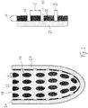
- Figure 1 shows in the left representation a liner 1 with a radial section along the longitudinal extent in which only the sectional plane is shown.
- the liner 1 is as formed closed liner and has a closed, distal end and an entry opening 18, via which a stump of a limb (not shown) can be introduced into the liner 1.
- the liner 1 has a base body 10 made of a flexible, water-impermeable and advantageously elastic material.
- the base body 10 has an inside 14 facing the stump in the applied state and an outside 12 facing away from the skin surface.
- the outer side 12 is designed to be closed, so that no moisture can penetrate from the stump through the base body 10 or reach the stump through the base body 10. Silicone or a plastic, for example polyurethane, can be used as the material for the base body 10.
- a large number of similar knobs 16 are formed on the inner side 14 of the base body 10, which protrude beyond the base body 10 in the direction of the skin surface.
- a coating 20 is applied, which consists of a material that is different from the material of the base body 10.
- the knobs 16, which have a flat surface 28 facing towards the skin surface, allow ventilation of the skin surface in those areas where the knobs 16 do not rest on the skin surface. This makes it possible to transport moisture and heat away from the liner 1 along the skin surface, so that warm air and moisture can escape at the distal edge 24 of the liner.
- the base body 10 and the knobs 16 protruding therefrom and directed towards the inside can be seen.
- the knobs 16 have a flat surface 28 and a knob height H which is smaller than the knob length L.
- the ratio of knob length L to knob height H is between 1.5 and 2.5, it being found to be more advantageous if the knob length L is in a range between 0.7 mm and 1.2 mm.
- the distances D between two knobs 16 are advantageously less than the knob height H and in the illustrated embodiment are approximately half the knob height. It can also be that the distances are chosen to be larger, so that the distance D between two knobs 16 can be up to 1.5 times the knob height H.
- the distance can be between 0.2mm and 1.2mm.
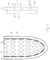
- FIG. 2 is an alternative representation of the liner 1 according to FIG Figure 1 shown.
- the shape of the knobs 16 is oval, the distance D is the smallest distance between two knobs 16, the knob length L denotes the larger longitudinal extent, the knob width B the smaller extent of the knobs 16.
- the ratio of knob length to knob width can be between 1 and 2.5.
- the arrangement of the knobs 16 runs essentially uniformly over the entire inside 14 of the base body 10, with inwardly open, interrupted channels 22 being formed between the knobs 16, which run essentially from distal to proximal and at the same time due to the arrangement of the knobs 16 Form circumferential channels at the same height, which intersect with the channels 22 in the proximal-distal direction, so that a free passage of heat and moisture from all parts of the body not covered by knob surfaces 28 to the proximal edge 22 is possible. The escape of heat and moisture takes place in the space between the base body 10 and the skin surface.
- the coating 22 is made of a material different from the material of the base body 10, the base body 10 and the knobs 16 are formed in one piece or in one piece and have good adhesion when placed on the skin.
- the outside coating 20 can be selected from a material that has particularly good mechanical properties and good durability, which does not necessarily have to coincide with skin compatibility, so that there is great freedom for the design of the liner 1 due to the use of two different materials.
- FIG Figure 3 shows a radial section analogous to FIG Figure 1 In the illustration on the right it is clear that the entire liner 1 is made from a single material and the knobs 16 are formed in one piece on the inside 14 of the base body 10.
- FIG. 4 A variant of the Figure 3 is in the Figure 4 shown, in which the knob shape according to Figure 2 corresponds, the knobs 16 and the base body 10 are not formed in one piece, but are attached to the base body 10 afterwards were, for example, by gluing or by subsequent networking and material connection.
- the liner 1 according to Figure 4 provides for the use of only one material.
- the subsequent application of the knobs 16 can cover a greater range of variation in the manufacture of liners, since individual peculiarities can be taken into account.
- FIG. 5 is a cross section through a liner 1 according to Figure 1 shown perpendicular to the longitudinal extension.
- the uniform arrangement of the knobs 16 on the inside 14 of the base body 10 results in the channels 22
- Figure 5 shows the closed cross section of the liner 1, so that the liner 1 can completely enclose the stump, not shown.
- the knob height H is equal to the knob width B equal to the distance D between two knobs 16 and thus also the width of the channels 22.
- FIG Figure 6 shows an alternative representation of the liner 1 according to FIG Figure 6 , in which the arrangement of the knobs 16 can be seen better.
- the knobs 16 extend along the essentially cylindrical side wall of the base body 10 as well as in the conically tapering distal end region, with no knobs 16 being provided at the lowest point of the liner.
- Figure 7 shows a cross-sectional representation of a liner according to Figure 3
- Figure 8 a cross section through a liner according to Figure 4 .
- the difference of the embodiments according to Figures 7 and 8th consists in that the base body 10 has no coating on the outside 12.
- the material of the knobs 16 in the embodiment of FIG Figures 4 and 8th can also differ from the material of the base body 10.
- FIG. 9 a plan view of the inside 14 of a base body 10 with different knob shapes is shown.
- the left representation provides oval knobs 16, the right representation rectangular knobs 16.
- the knobs 16 run essentially parallel, in the left representation the knobs are offset in height so that diagonally running channels 22 Form next to the parallel running channels 22, in the right illustration the knobs 16 on the base body 10 are uniform distributed and run parallel to each other.
- the base body 10 can be provided with closure or fastening elements, not shown, so that it can be wrapped around a stump or a limb and attached to it, so that a liner that is open at the distal edge 26 and at the proximal edge 24 is created, which acts as an interface for a prosthetic or orthotic fitting can serve.
- closure or fastening elements not shown
- the knobs in the embodiment according to Figure 9 can be formed from a material different from the base body 10.
- Figure 10 is the plan view of the base body according to Figure 9 shown with knobs 16 made of the same material as the base body 10.
- the knobs 16 according to Figure 10 can be molded on during the primary forming process of the base body 10 or applied subsequently.
- the knobs 16 on both base bodies 10 form a structured surface with alternating elevations and depressions, so that air can circulate and moisture can be removed in the spaces between the knobs.
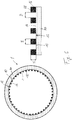
- the liner 1 is shown in a radial section with a base body 10 and an outer side 12.
- the insertion opening 18 on the distal edge 24 enables the liner 1 to be turned over and entered.
- webs 16 ' are provided which extend radially inward, so that channels 22 are formed between the webs 16' extend from the closed distal end to the open proximal rim 24.
- the channels 22 are oriented essentially in a straight line on the inside of the base body 10 and allow a direct removal of sweat and an exchange of air.
- the base body 10 is designed with closed walls and essentially impermeable to water.
- Figure 12 shows a detailed representation of the liner 1 with the base body 10 and the web 16 'protruding radially inward.
- the height H of the web 16 ' is dimensioned such that, on the one hand, there is sufficiently high stability against deformation when a compressive force is applied and, on the other hand, there is a sufficient distance between the inside of the base body 10 and the not shown Skin surface is provided to allow the removal of air and moisture.
- Figure 13 shows a cross section through the liner 1, from the figure it can be seen that the liner 1 has an essentially circular cross section and a closed structure of the base body 10.
- the projections formed as webs 16 ' which protrude radially inward from the inside 14 of the base body 10, run from the proximal edge to the distal tip.
- the channels 22 are formed between the webs 16 'in order to transport away air and moisture.
- a sectional view is in the Figure 14 from which it can be seen that the height H and the width B of the webs 16 'essentially correspond to one another, so that a square cross-section, starting from the base body 10, results for the web 16'.
- the distance D between two webs 16 'corresponds essentially to the width B of the web 16', a possible range of dimensions for the height H, the width B and the distance D is between 0.3 and 0.7 mm, but is not restricted to this .
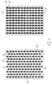
- Figure 15 shows a first variant of the inside of a liner in a plan view, in which, in addition to knobs 16 of different sizes and orientations, webs 16 ′ are applied or formed in oval shape on the base body 10.
- the channels 22 are formed between the webs 16 ′ and knobs 16.
- the Figure 15 it can be seen that the webs 16 'do not have to run continuously from the distal to the proximal end; rather, interruptions are also possible.
- a knob 16 is arranged between two web sections 16 '. In principle, it is possible to arrange knobs 16 and webs 16 ′ of different sizes and orientations on the inside of the base body 10.
- FIG. 16 Another variant is in the Figure 16 shown, in which a plurality of webs 16 'are arranged uniformly spaced from one another on the inside of the base body 10. Correspondingly uniform, rectilinear channels 22 are formed between the webs 16 '.
Landscapes
- Health & Medical Sciences (AREA)
- Cardiology (AREA)
- Oral & Maxillofacial Surgery (AREA)
- Transplantation (AREA)
- Engineering & Computer Science (AREA)
- Biomedical Technology (AREA)
- Heart & Thoracic Surgery (AREA)
- Vascular Medicine (AREA)
- Life Sciences & Earth Sciences (AREA)
- Animal Behavior & Ethology (AREA)
- General Health & Medical Sciences (AREA)
- Public Health (AREA)
- Veterinary Medicine (AREA)
- Orthopedics, Nursing, And Contraception (AREA)
- Prostheses (AREA)
Description
- Die Erfindung betrifft einen Liner zur Anlage an einer Hautoberfläche mit einem Grundkörper aus einem flexiblen, wasserundurchlässigen Material mit einer im angelegten Zustand von der Hautoberfläche abgewandten Außenseite und einer im angelegten Zustand der Hautoberfläche zugewandten Innenseite.
- Liner aus dem Stand der Technik sind dafür vorgesehen, an einen Stumpf einer Gliedmaße angelegt zu werden, um eine Schnittstelle insbesondere zu einer Prothese herzustellen. Die Liner können als Kunststoff- oder Silikonliner ausgebildet sein und weisen in der Regel einen geschlossenen Querschnitt auf, so dass sie den Stumpf luftdicht umschließen. Die Innenseite kann mit einer auf der Hautoberfläche haftenden Beschichtung versehen sein. Der Stumpf wird zusammen mit dem Liner in einen Prothesenschaft eingeführt und legt den Liner in dem Prothesenschaft über eine Verriegelungseinrichtung oder über einen Unterdruck fest. Die Erzeugung des Unterdruckes im Rahmen der sogenannten Saugschaftlinertechnologie erfolgt dadurch, dass der Prothesenschaft gegenüber dem Prothesenliner luftdicht abgedichtet und aus dem Zwischenraum zwischen dem Prothesenliner und dem Prothesenschaft die darin vorhandene Luft abgesaugt oder herausgedrückt wird. Ein Rückströmen in den Zwischenraum wird über ein Rückschlagventil verhindert.
- Die
WO 2012/051385 A1 betrifft einen Prothesenliner, der als Interface zwischen einem Stumpf und einem Prothesenschaft ausgebildet ist. Der Prothesenliner weist einen langgestreckten, im Wesentlichen konischen Grundkörper auf, in dem ein Volumensteuerkissen angeordnet ist. An der Außenseite des Prothesenliners sind im Distalbereich radial nach außen gerichtete, umlaufende Dichtlippen angeordnet, um eine verbesserte Abdichtung gegenüber der inneren Oberfläche eines Prothesenschaftes bereitzustellen. - Eine ähnliche Ausgestaltung eines Liners ist in der
US 8,052,760 B2 beschrieben, bei der im äußeren Umfang des Prothesenliners Dichtelemente angeordnet sind, um eine verbesserte Abdichtung des Zwischenraumes zwischen dem Prothesenliner und dem Prothesenschaft zu gewährleisten. - Die
DE 101 53 796 A1 betrifft unter anderem einen Liner zur Verwendung mit einem becherförmigen Prothesenschaft, der an seinem distalen Ende eine Öffnung aufweist, durch die eine Schnur zum Einziehen des Liners hindurchgeführt werden kann. Über einen mechanischen Verriegelungsstift wird der Liner in dem Prothesenschaft verriegelt. - Das Problem bei Prothesenlinern dieser Art besteht darin, dass die natürlichen Wärmeregulationsmechanismen wie Wärmeleitung, Wärmeströmung, Wärmestrahlung und Verdunstung des Menschen bei einem vollflächigen unmittelbaren Hautkontakt mit der Lineroberfläche nur eingeschränkt wirksam sind. Ein Wärmestrom in Form von Konvektion kann bei einem vollständigen Kontakt zur Haut nicht stattfinden, auch ist die Verdunstung von Schweiß durch die verwendeten Materialien nur eingeschränkt möglich.
- Die
US 8,182,547 B2 sieht daher auf der Innenseite eines Liners eine viellagige Textilschicht vor, wobei der proximale Rand eine luftdichte Abdichtung gewährleistet. Über Belüftungskanäle kann Luft in den Zwischenraum zwischen der Textilschicht und der Hautoberfläche eingeleitet und abgesaugt werden, um sowohl den Unterdruck als auch die Belüftung zu steuern. - Die
US 6,974,484 B2 sieht zum Abtransport von Schweiß das Einlegen einer osmotischen Membran vor, die von einem Liner abgedeckt wird. Die osmotische Membran ermöglicht den Abtransport von Feuchtigkeit von dem Stumpf, sperrt aber gegen einen Rückstrom. - Die
US 2012/0191218 A1 betrifft ein vakuumunterstütztes Trägersystem für Protheseneinrichtungen an unteren Extremitäten mit einem luftundurchlässigen Schaft mit Anschlüssen für eine Vakuumquelle, einem Liner, der an seinen Rändern luftdicht abgedichtet ist und zwischen seinen Rändern poröse Bereiche aufweist. Der Liner ist gegenüber dem Schaft abgedichtet und zwischen dem Liner und dem Schaft ist eine luftdurchlässige Verteilschicht z.B. aus einem Textil angeordnet, um das an den Schaft angelegte Vakuum zu verteilen. Über eine Pumpe können Luft und Feuchtigkeit von der Hautoberfläche weg transportiert und aus dem Schaft abgesaugt werden. - Die
WO 2009/017762 A2 betrifft einen Liner zur Verwendung in prothetischen oder orthetischen Vorrichtungen. Der Liner weist eine innere Schicht mit rutschhemmenden Komponenten auf, die zumindest einen Teil des Umfanges der inneren Lineroberfläche bilden. Die innere Schicht bildet eine Vielzahl von Öffnungen aus, die zu einem porösen Element führen. Durch die Öffnungen in der inneren Schicht wird die Feuchtigkeit von dem Stumpf weg und durch das poröse Element an die Umgebung abgegeben. Die Öffnungen können bereichsweise auf der Innenseite angeordnet sein. In dem porösen Material können absorbierende Elemente gespeichert sein. Eine geschlossene Außenschicht kann die perforierte Schicht umgeben. Eine Variante sieht vor, dass der Liner aus zwei oder mehreren Schichten zusammenhängender Polymerbälle besteht, wobei die aneinander anliegenden Bälle miteinander verbunden sind und den gleichen Durchmesser haben können. - Die
US 8,282,686 B2 betrifft eine Prothesenschaftanordnung zur Aufnahme eines Amputationsstumpfes mit einer formstabilen Außenschale, die der Form des aufzunehmenden Stumpfes entspricht. Eine luftdurchlässige Innenschicht ist auf der Innenseite der Außenschale an ausgewählten Bereichen angeordnet, um mit der Hautoberfläche in Kontakt zu treten und das angelegte Vakuum zu verteilen. Die Innenschicht ist aus einem mehrlagigen Textil ausgebildet. An der Außenschale ist ein Einlass und ein mit einer Vakuumquelle verbundener Auslass vorgesehen. - Die
EP 2 353 550 A1 beschreibt ein Bauteil für eine künstliche Gliedmaße mit einem Grundkörper, der aus einem luftdurchlässigen Gewebe hergestellt ist. Eine Vielzahl von Vorsprüngen aus Silikon sind auf der Innenseite und der Außenseite des Grundkörpers angeordnet, wobei benachbarte Vorsprünge voneinander beabstandet sind. - Die
US 2010/274364 A1 betrifft eine einstellbare Prothese mit einem darin angeordneten Liner, der eine Ventilationsschicht sowie eine Membran aufweist. Die Ventilationsschicht weist radial nach außen gerichtete Durchgangslöcher auf, die Feuchtigkeit zu der außen liegenden Membran transportieren. In einer Variante ist vorgesehen, dass in Längserstreckung des Liners gerichtete Kanäle auf der Innenseite mit einer feuchtigkeitsdurchlässigen Membran abgedeckt sind. In einer weiteren Variante sind längsgerichtete Kanäle in einer Belüftungsschicht oder in einem Liner ausgebildet, die über Durchgangslöcher mit der Oberfläche des Stumpfes in Kontakt stehen. - Die
EP 0 363 654 A2 betrifft eine Prothese mit Mitteln zum Belüften einer Grenzoberfläche zwischen einem Stumpf und einer Prothese. Die Belüftungsmittel sehen eine Aufnahme vor, die luftdurchlässig ist und eine Form aufweist, die dem Stumpf entspricht. Eine Lüftungseinrichtung kann über einen Verbindungskanal mit der Aufnahme verbunden sein. Die Aufnahme kann als Hülse ausgebildet sein, die auch aus einem porösen Material hergestellt sein kann, das ein Durchströmen des Lüftungsmediums ermöglicht. Auf der Innenseite der Hülse können Kanäle und/oder Öffnungen eingearbeitet sein. - Die
EP 0346697 A2 betrifft eine orthopädische Vorrichtung wie eine Prothese, Gipsschiene oder Luftschiene, die eine auf der Haut des Patienten aufliegende Aufstandsfläche aufweist. Die Aufstandsfläche ist mit einem flächigen, flexiblen Ventilationsschichtmaterial ausgekleidet. In dem Material sind Längsluftkanäle und Querluftkanäle vorhanden, wobei das Material eine Druckstabilität aufweist, die bei einem normalen Gebrauch die Luftleitfähigkeit in Längsrichtung und Querrichtung aufrechterhält. Das Material kann verschieden strukturiert sein, beispielsweise offenporig, rippenartig, genoppt, mit Stegen versehen, netzartig dreidimensional oder dergleichen, wobei wesentlich ist, dass Längsluftkanäle und mit diesen in Verbindung stehende Querluftkanäle bis zu mindestens einer Oberflächliche hin entstehen. - Aufgabe der vorliegenden Erfindung ist es, einen Liner bereitzustellen, mit dem einerseits eine gute Wärmeregulierung und andererseits ein angenehmes Tragempfinden erreicht werden kann.
- Erfindungsgemäß wird diese Aufgabe durch einen Liner mit den Merkmalen des Hauptanspruches gelöst. Vorteilhafte Ausgestaltungen und Weiterbildungen der Erfindung sind in den Unteransprüchen, der Beschreibung und den Figuren aufgeführt.
- Der Liner zur Anlagen an einer Hautoberfläche mit einem Grundkörper aus einem flexiblen, wasserundurchlässigen Material mit einer im angelegten Zustand von der Hautoberfläche abgewandten Außenseite und einer im angelegten Zustand der Hautoberfläche zugewandten Innenseite sieht vor, dass auf der Innenseite zur Hautoberfläche hin offene Kanäle angeordnet sind. Dadurch ist es möglich, dass einerseits ein Kontakt der Innenseite des Liners mit der Hautoberfläche stattfindet und andererseits ein Wärmestrom in Form von Konvektion und einer Verdunstung von Schweiß gleichermaßen ermöglicht wird. Es wird somit ein unmittelbarer Kontakt des Liners sowohl zu der Hautoberfläche als auch zu der Innenseite des Prothesenschaftes hergestellt und darüber der Prothesenschaft mit der Gliedmaße gekoppelt. Darüber hinaus wird durch die und entlang der Kanäle zwischen den Anlageflächen ein unmittelbar an der Hautoberfläche entlang geführter Wärme- und Feuchtigkeitstransport durchgeführt, wodurch die natürlichen Wärmeregulationsmechanismen aufrecht erhalten bleiben und angenehmes Traggefühl vermitteln. Der Liner ist aus wasserundurchlässigen Materialien oder einem einzigen Material hergestellt, was verhindert, dass Feuchtigkeit von der der Hautoberfläche durch das Material hindurch abtransportiert wird, wobei Materialien so beschaffen sind, dass sie einen Wasserdurchtritt in flüssiger Form verhindern. Als wasserundurchlässige Materialien eignen sich insbesondere Elastomere, Silikone und gummiartige Werkstoffe oder auch geschlossenporige Schäume. Die Liner dienen als Interface zwischen dem Stumpf und einem Prothesenschaft. Durch die auf der Oberfläche der Haut stattfindende Verdunstung findet eine effektive Kühlung der Hautoberfläche statt, was den Tragekomfort merklich erhöht. Der Grundkörper weist vorteilhafterweise eine geschlossene Außenseite auf, um zu verhindern, dass Feuchtigkeit nach außen gelangt, so dass sich keine Feuchtigkeit zwischen dem Liner und dem Prothesenschaft ansammeln kann.
- Der Grundkörper kann einen geschlossenen Querschnitt mit einer proximalen Einstiegsöffnung aufweisen, so dass er als im Wesentlichen konischer Hohlkörper ausgebildet ist. Das distale Ende des Prothesenliners ist üblicherweise geschlossen ausgebildet oder weist zumindest eine Öffnung zum Abtransport von Feuchtigkeit auf.
- Alternativ dazu kann der Grundkörper eine Öffnung am distalen Ende aufweisen oder aber als offener Querschnitt mit Verschlusselementen versehen sein, so dass der zunächst flächige Prothesenliner um den Stumpf herum angelegt und über die Verschlusselemente unter Ausbildung eines ringförmigen Liners daran festgelegt werden kann.
- Auf der Außenseite des Liners kann eine Textilschicht aufgebracht oder befestigt sein, die die Außenoberfläche des Liners ganz oder teilweise abdeckt. Die Textilschicht wird aufgrund der geschlossenen, wasserundurchlässigen Oberfläche des Liners von der innerhalb des Liners befindlichen Feuchtigkeit ferngehalten, der Liner wirkt als Feuchtigkeitssperre zwischen der Hautoberfläche und der Außenseite des Liners bzw. der Textilschicht. Die Verdunstung innerhalb des Liners in den Kanälen oder Zwischenräumen bewirkt eine Kühlung, ohne die Außenseite des Liners zu beeinträchtigen oder einen Stoffdurchtritt nach außen zu erlauben.
- Auf der Außenseite des Grundkörpers kann eine Beschichtung aufgebracht sein, die vom Material des Grundkörpers abweicht. Dadurch ist es möglich, mehrschichtige Liner mit unterschiedlichen Eigenschaften herzustellen, so dass beispielsweise auf der Innenseite besonders hautverträgliche Materialien mit einer guten Haftfähigkeit eingesetzt werden können, während auf der Außenseite besonders stabile und abriebfeste Materialien Einsatz finden können. Die äußere Beschichtung kann auch ein Textil sein oder textile Komponenten aufweisen. Auf der Außenseite des Grundkörpers kann auch ein Bezug oder ein Überzug reversibel aufgebracht sein, so dass der Liner als Innenliner mit Kanälen oder Noppen und einem Außenliner gebildet sein kann.
- Die zur Hautoberfläche hin offenen Kanäle sind vorteilhafterweise von Noppen ausgebildet, so dass die Kanäle um die Noppen herumgeführt sind. Dadurch ist es möglich, eine große Fläche bereitzustellen, entlang der die Luft über die Hautoberfläche strömen kann, um einen Wärme- und Feuchtigkeitstransport zu erreichen. Durch die Ausgestaltung der Kanäle durch die Noppen ist es möglich, sich kreuzenden und in verschiedene Richtungen orientierte Kanäle bereitzustellen, so dass neben der üblichen Strömungsrichtung, die der Konvektion folgt, auch quer oder schräg dazu verlaufende Strömungsrichtungen und Luftströmungen erfolgen können, die beispielsweise einer Pumpbewegung aufgrund der dynamischen Belastung beim der Benutzung einer Prothese folgt. Durch sich kreuzenden oder schneidende Kanäle wird die Entlüftung und der Wärme- und Feuchtigkeitstransport weiter verbessert. Alternativ oder ergänzend zu den Noppen können die Kanäle auch durch Stege ausgebildet sein, die auf der Innenseite des Grundkörpers angeordnet sind.
- Die Noppen oder Stege sind einstückig mit dem Grundkörper ausgebildet, beispielsweise im Herstellverfahren des Liners. Zur Herstellung der Noppen oder Stege können in eine im Wesentlichen glattwandige Innenwand Kanäle eingebracht, beispielsweise eingefräst oder eingeschnitten werden, alternativ sind die Noppen oder Stege in der Form eingebracht und werden bei dem Herstellprozess des Liners, insbesondere beim Gießen, gebildet. Die Noppen oder Stege sind dann integraler Bestandteil des einstückig ausgebildeten Liners. Noppen sind dabei als Erhebungen anzusehen, die über eine Grundfläche herausstehen, wobei die einzelnen Erhebungen isoliert voneinander sind, wodurch sich eine strukturierte Oberfläche mit Erhebungen und Vertiefungen ausbildet. Die Erhebungen und Vertiefungen können regelmäßig oder unregelmäßig auf der Innenseite verteilt sein, ebenso ist es möglich, dass die Noppen voneinander verschiedene Formen und Größen aufweisen, um eine Anpassung an lokale Belastungen vornehmen zu können. Stege weisen im Gegensatz zu den Noppen eine größere Längserstreckung auf und können sich von einem Ende des Liners bis zum anderen Ende erstrecken.
- Die Noppen und/oder Stege können in einer regelmäßigen Anordnung auf der Innenseite angeordnet sein, beispielsweise in verschiedenen Mustern, um eine Beeinflussung der Wärmeregulation und des Abtransportes von Feuchtigkeit zu ermöglichen. Insbesondere kann eine lineare Anordnung der Noppen und/oder Stege in Richtung von dem distalen Ende zum proximalen Ende erfolgen, um die natürliche Strömungsrichtung erwärmter Luft nach oben auszunutzen und schnellstmöglich diese Luft mit der darin enthaltenen Feuchtigkeit abzuleiten. Ebenfalls ist es möglich, die Noppen und/oder Stege so anzuordnen, dass sie in Umfangsrichtung verlaufende Kanäle, gegebenenfalls spiralförmige Kanäle, aufweisen, um eine Leitungsfunktion der Luftströmung zu erreichen. Die Noppen können in Umfangsrichtung versetzt zueinander angeordnet sein, um bestimmte Vorzugsrichtungen von Strömungen erreichen zu können.
- Die Noppen und/oder Stege können auf der gesamten Innenseite angeordnet sein, um eine möglichst gleichmäßige Anlagen und Druckverteilung auf der Stumpfoberfläche zu erreichen. Neben der Anordnung vollflächiger Muster oder der kompletten Bestückung der Innenseite mit gleichmäßig verteilten Noppen und/oder Stege sind nur partielle Bestückungen mit Noppen und/oder Stegen möglich und vorgesehen, so dass nur einzelne Noppen- oder Stegbereiche auf der Innenseite angeordnet sind, um an besonders problematischen Stellen des Stumpfes eine natürliche Wärmeregulation ermöglichen zu können. Wichtig ist dabei, dass über die Steg- oder Noppenzwischenräume der Transport sowohl von erwärmter Luft als auch Feuchtigkeit gegeben ist.
- Die Noppen und/oder Stege können eine zur Hautoberfläche gerichtete ebene Oberfläche aufweisen, wobei auch eine leichte Wölbung von der Hautoberfläche weg möglich ist, um bei einer Druckbelastung einklemmende Hautbereiche zu vermeiden. Die Oberfläche der Noppen und/oder Stege kann eine Rauhigkeit aufweisen, um einen verbesserten Komfort aufgrund der nicht vollständig glatten Oberfläche zu erreichen.
- Das Verhältnis von Noppenlänge zu Noppenbreite kann zwischen 0,8 und 2,5 liegen, wodurch gewährleistet wird, dass für den Abtransport der Luft ausreichend große Kanäle oder Zwischenräume vorhanden sind und andererseits das Tragegefühl der Patienten weiterhin angenehm bleibt.
- Das Verhältnis von Noppenlänge zu Noppenhöhe kann zwischen 1,5 und 2,5 liegen, wodurch gewährleistet wird, dass die Noppen nicht zu hoch sind und ein zu tiefes Eindrücken der Noppen in die Hautoberfläche verhindert wird. Andererseits ist die Noppenhöhe ausreichend groß, um einen Luftstrom zu gewährleisten, um Wärme und Feuchtigkeit abzutransportieren.
- Der Abstand zwischen zwei Noppen kann zwischen der Hälfte der Noppenhöhe und dem 1,5fachen der Noppenhöhe liegen, so dass eine ausreichende Luftzirkulation vorhanden ist. Die Kanäle sind dann ausreichend groß, um den benötigten Abtransport der Wärme in Form von Konvektion und Schweißverdunstung zu ermöglichen.
- Die Noppen und/oder Stege selbst können eine Höhe zwischen 0,25 mm und 2 mm, bevorzugt zwischen 0,5 mm und 1mm aufweisen, um einerseits eine ausreichende Höhe für die Luftzirkulation und den Schweißabtransport und andererseits eine ausreichende Stabilität gegen ein Umklappen oder ein Verschieben der Lineraußenseiten gegenüber der Hautoberfläche bereitzustellen. Die Steg- und/oder Noppenhöhe kann zwischen 5% und 25% der relativen Wandstärke des Liners betragen, also der Wanddicke des Liners an der Basis der Noppe oder des Steges.
- Die Noppenform ist bevorzugt rund, insbesondere oval oder rechteckig, wodurch eine Ausbildung von Oberflächenkanälen und eine gerichtete Strömung erreicht werden können.
- Das Verhältnis von Noppenhöhe zu Noppenbreite oder Steghöhe und Stegbreite ist bevorzugt kleiner als 1, so dass die Breite der Noppen oder Stege größer als deren Höhe ist, wodurch verhindert wird, dass die zwischen den Noppen und/oder Stegen befindlichen Kanäle bei einer großen Druckbelastung durch sich verformende Noppen und/oder Stegen blockiert werden. Das vorgeschlagene Verhältnis stellt sicher, dass die Zwischenräume im Wesentlichen durchgängig bleiben.
- Zur Unterstützung der Wärmeregulierung können eine oder mehrere Anschlusseinrichtungen für eine Belüftungseinrichtung vorgesehen sein, so dass beispielsweise Pumpen oder Ventilatoren an den Liner angeschlossen werden können, um Luft abzusaugen, hineinzudrücken oder auch Feuchtigkeit aus dem Linerinnenraum abzutransportieren.
- Die insbesondere durch die Noppen ausgebildeten Kanäle können bis zu dem proximalen oder distalen Rand des Prothesenliners reichen. Sie können als Belüftungs- oder Absaugkanäle ausgebildet sein, wodurch es möglich ist, dass eine Durchlüftung der Hautoberfläche, die nicht mit den Noppenoberflächen oder Stegoberflächen oder den Kanalzwischenmaterial in direktem Kontakt steht, stattfindet. Bei einer Luftzufuhr von außen ist eine stete Durchlüftung der Zwischenräume oder Kanäle gewährleistet. Die Ausgestaltung als Absaugkanäle sieht vor, dass diese in strömungstechnischer Verbindung zu einer Pumpeinrichtung stehen, beispielsweise einer Saugpumpe, die mechanisch oder elektrisch angetrieben wird. Ebenso ist es möglich, eine Belüftung durchzuführen, wenn die Kanäle mit einer Belüftungseinrichtung in Verbindung stehen, beispielsweise einer druckseitig angeschlossenen Pumpe. Durch eine Umschaltung der Pumpe von Saug- auf Druckbetrieb ist es möglich, die Kanäle und die Pumpe für unterschiedliche Betriebsarten zu nutzen, nämlich als aktive Belüftung oder aktive Absaugung. Reichen die Kanäle bis zu dem proximalen und/oder distalen Rand des Liners, findet eine Be- und Entlüftung der Kanäle und damit des Freiraumes oberhalb der Haut über einen Differentialdruck statt, der zwischen dem Inneren des Liners und der Umgebung herrscht. Bei einem Überdruck entweicht Luft aus dem Liner, bei einem Unterdruck strömt Luft in den Liner hinein, genauer gesagt in die Kanäle, die durch die Noppen ausgebildet werden. Sowohl bei der passiven, mit Differentialdruck betriebenen, als auch bei der aktiven, mit eine Pumpe bewirkten Belüftung oder Entlüftung kann der proximale Rand des Liners geschlossen ausgebildet sein, wenn eine Zufuhr von Luft über Be- oder Entlüftungsöffnungen, ggf. mit einem Ventil versehen, erfolgt. Der proximale Rand des Liners kann durch den Liners selbst oder mit einer Manschette abgedichtet sein, so dass der Schweißdampf im distalen Endbereich abgeführt wird, beispielsweise durch eine entsprechende Auslassöffnung, ggf. mit einem Ventil. Der Volumenausgleich bei einem abgedichteten Rand findet durch die Schweißproduktion und den Phasenwechsel von flüssig zu gasförmig bei der Verdunstung statt. Wird nicht die gesamte Feuchtigkeit verdunstet, kann der Schweiß in flüssiger Form abgeführt werden, was zu einer trockenen Hautoberfläche und einer dadurch verbesserten Hygiene führt. Soll Unterdruck an den Liner angelegt werden, kann dies neben einer separaten Pumpe auch über einen ggf. zwischen dem Schaft und dem Liner anliegenden Unterdruck geschehen, indem eine strömungstechnische Verbindung von dem Schaftinnenraum zu dem Linerinnenraum hergestellt wird. So kann auf eine gesonderte Pumpe verzichtet werden.
- In dem Liner kann zumindest ein Anschluss zum Be- oder Entlüften angeordnet sein, der mit den Kanälen in strömungstechnischer Verbindung steht, um zu gewährleisten, dass Wärme und Feuchtigkeit aus dem Liner abtransportiert werden oder eine ausreichende Belüftung der Hautoberfläche erfolgt. Der Anschluss kann an dem distalen Ende des Liners oder an dem proximalen Rand angeordnet sein. Die Anordnung des Anschlusses an dem distalen Ende hat den Vorteil, dass er in der Regel an dem während des Stehens und Gehens tiefsten Punkt des Liners liegt, wodurch sich schwerkraftbedingt eine Fließrichtung für Feuchtigkeit ergibt, die zum Abtransport der Feuchtigkeit genutzt werden kann. Der Anschluss kann mit einer Verriegelungseinrichtung für den Liner in einem Schaft gekoppelt sein und in einem sogenannten Shuttle-Lock integriert sein.
- Eine Weiterbildung der Erfindung sieht vor, dass ein Phasenwechselmaterial an dem Liner angeordnet oder in dem Liner integriert ist. Mit der Verwendung eines Phasenwechselmaterials, auch PCM genannt, ist es möglich, einen kühlenden Effekt auf den Luftstrom auszuüben, der sich in dem Bereich der Kanäle oder des Zwischenraumes zwischen der Haut und dem Liner ergibt. Über die PCM ist es möglich, eine aktive Kühlung für den Nutzer des Liners bereitzustellen, indem die Enthalpie thermodynamischer Zustandsänderungen eines Speichermediums ausgenutzt wird. Zwischen der Hautoberfläche und dem Liner findet eine Belüftung in den Kanälen statt, so dass die Schweißverdunstung zur Kühlung beiträgt. Über das Phasenwechselmaterial oder die Phasenwechselmaterialien ist es möglich, eine verstärkte Kühlwirkung zu erzielen, beispielsweise indem der Luftstrom innerhalb des Liners gleichzeitig von dem Phasenwechselmaterial gekühlt wird.
- Es ist möglich, dass die Kanäle in einem direkten Kontakt mit dem Phasenwechselmaterial stehen, beispielsweise indem zumindest ein Teil der Kanalwände aus einem Phasenwechselmaterial besteht oder mit diesem beschichtet ist, so dass die Kanäle in direkter strömungstechnischer Verbindung mit einem Phasenwechselmaterial stehen. Zusätzlich ist es möglich, dass eine Pumpe vorgesehen ist, um die Luftströmung zu befördern. Die Durchströmung der Kanäle kann durch einen angelegten Unterdruck erfolgen, wodurch die Verdunstung des Körperschweißes erleichtert wird, was zur verbesserten Kühlung beiträgt. Sofern keine oder eine verringerte Kühlung gewünscht wird, kann über eine Schaltung oder Steuerung vorgesehen werden, dass der Luftaustausch reduziert wird, so dass eine Verringerung oder Vermeidung eines Wärmetransportes bewirkt wird.
- Nachfolgend werden Ausführungsbeispiele der Erfindung anhand der beigefügten Figuren näher erläutert. Es zeigen:
- Figur 1 -
- einen Radialschnitt durch einen Liner und eine Detaildarstellung;
- Figur 2-
- einen Radialschnitt in Draufsicht gemäß
Figur 1 ; - Figur 3 -
- einen Radialschnitt durch einen einstückigen Liner mit Detaildarstellung;
- Figur 4 -
- einen Radialschnitt in Draufsicht und eine Detaildarstellung mit separaten Noppen, die nicht von der Erfindung umfasst sind;
- Figur 5 -
- eine Querschnittsdarstellung mit einer Detailansicht;
- Figur 6 -
- eine Querschnittsdarstellung gemäß
Figur 5 in Draufsicht; - Figur 7 -
- eine einstückige Variante eines Liners gemäß
Figur 5 ; - Figur 8 -
- eine Draufsicht auf einen Querschnitt eines Liners mit separaten Noppen, die nicht von der Erfindung umfasst sind;
- Figur 9 -
- eine Draufsicht auf zwei Ausführungsformen;
- Figur 10 -
- eine Variante der
Figur 9 ; - Figur 11 -
- einen Radialschnitt;
- Figur 12 -
- eine Detaildarstellung der
Figur 11 ; - Figur 13 -
- eine Querschnittsansicht der
Figur 11 ; - Figur 14 -
- eine Detailansicht der
Figur 13 ; - Figur 15 -
- eine Draufsicht auf eine Variante; sowie
- Figur 16 -
- eine Draufsicht auf eine weitere Variante.
-
Figur 1 zeigt in der linken Darstellung einen Liner 1 mit einem Radialschnitt entlang der Längserstreckung, in der nur die Schnittebene dargestellt ist. Der Liner 1 ist als geschlossener Liner ausgebildet und weist ein geschlossenes, distales Ende und eine Einstiegsöffnung 18 auf, über die ein nicht dargestellter Stumpf einer Gliedmaße in den Liner 1 eingeführt werden kann. Der Liner 1 weist einen Grundkörper 10 aus einem flexiblen, wasserundurchlässigen und vorteilhafterweise elastischen Material auf. Der Grundkörper 10 weist eine im angelegten Zustand dem Stumpf zugewandte Innenseite 14 und eine der Hautoberfläche abgewandte Außenseite 12 auf. Die Außenseite 12 ist geschlossen ausgebildet, so dass keine Feuchtigkeit von dem Stumpf durch den Grundkörper 10 nach außen dringen oder durch den Grundkörper 10 an den Stumpf gelangen kann. Als Material für den Grundkörper 10 kann Silikon oder ein Kunststoff, beispielsweise Polyurethan verwendet werden. Auf der Innenseite 14 des Grundkörpers 10 sind eine Vielzahl gleichartiger Noppen 16 ausgebildet, die in Richtung auf die Hautoberfläche über den Grundkörper 10 hinausragen. Auf der Außenseite 12 des Grundkörpers 10 ist eine Beschichtung 20 aufgebracht, die aus einem Material besteht, das von dem Material des Grundkörpers 10 verschieden ist. Durch die Noppen 16, die eine zur Hautoberfläche hingewandte, ebene Oberfläche 28 aufweisen, wird eine Belüftung der Hautoberfläche an denjenigen Bereichen ermöglicht, an denen die Noppen 16 nicht auf der Hautoberfläche aufliegen. Dadurch ist es möglich, Feuchtigkeit und Wärme aus dem Liner 1 entlang der Hautoberfläche abzutransportieren, so dass warme Luft und Feuchtigkeit am distalen Rand 24 des Liners austreten kann. - In der rechten Darstellung der
Figur 1 ist eine vergrößerte Detailansicht einer Linerwand mit einer außenseitigen Beschichtung 20, dem Grundkörper 10 sowie den davon hervorstehenden, zur Innenseite gerichteten Noppen 16 zu erkennen. Die Noppen 16 weisen eine ebene Oberfläche 28 und eine Noppenhöhe H auf, die kleiner als die Noppenlänge L ist. Das Verhältnis von Noppenlänge L zu Noppenhöhe H liegt zwischen 1,5 und 2,5, wobei es sich als vorteilhafter herausgestellt hat, wenn die Noppenlänge L in einem Bereich zwischen 0,7mm und 1,2mm ausgebildet ist. Die Abstände D zwischen zwei Noppen 16 sind vorteilhafterweise geringer als die Noppenhöhe H und betragen im dargestellten Ausführungsbeispiel ungefähr die Hälfte der Noppenhöhe. Es kann auch sein, dass die Abstände größer gewählt sind, so dass der Abstand D zwischen zwei Noppen 16 bis zum 1,5fachen der Noppenhöhe H betragen kann. Der Abstand kann zwischen 0,2mm und 1,2mm betragen. - In der
Figur 2 ist eine alternative Darstellung des Liners 1 gemäßFigur 1 gezeigt. In der linken Darstellung ist zu erkennen, dass die Form der Noppen 16 oval ist, der Abstand D ist der jeweils kleinste Abstand zwischen zwei Noppen 16, die Noppenlänge L bezeichnet dabei die größere Längserstreckung, die Noppenbreite B die kleinere Ausdehnung der Noppen 16. Das Verhältnis von Noppenlänge zu Noppenbreite kann zwischen 1 und 2,5 liegen. Die Anordnung der Noppen 16 verläuft im Wesentlichen gleichmäßig über die gesamte Innenseite 14 des Grundkörpers 10, wobei sich zwischen den Noppen 16 nach innen offene, unterbrochene Kanäle 22 ausbilden, die einmal im Wesentlichen von distal nach proximal verlaufen und gleichzeitig aufgrund der Anordnung der Noppen 16 auf gleicher Höhe umlaufende Kanäle ausbilden, die sich mit den Kanälen 22 in proximal-distal-Richtung kreuzen, so dass ein freier Durchgang von Wärme und Feuchtigkeit von allen nicht von Noppenoberflächen 28 abgedeckten Körperpartien zum proximalen Rand 22 möglich ist. Der Austritt von Wärme und Feuchtigkeit erfolgt dabei in dem Zwischenraum zwischen dem Grundkörper 10 und der Hautoberfläche. - In der rechten Darstellung ist zu erkennen, dass die Beschichtung 22 aus einem von dem Material des Grundkörpers 10 verschiedenen Material besteht, der Grundkörper 10 und die Noppen 16 sind einteilig bzw. einstückig ausgebildet und weisen eine gute Haftfähigkeit bei Anlage auf der Haut auf. Die außenseitige Beschichtung 20 kann aus einem Material gewählt sein, das besonders gute mechanische Eigenschaften und eine gute Dauerhaltbarkeit aufweist, was nicht unbedingt mit einer Hautverträglichkeit zusammenfallen muss, so dass für die Gestaltung der Liner 1 durch die Verwendbarkeit zweier verschiedener Materialien große Freiheiten vorhanden sind.
-
Figur 3 zeigt einen Radialschnitt analog zurFigur 1 , in der rechten Darstellung wird deutlich, dass der gesamte Liner 1 aus einem einzigen Material hergestellt ist und die Noppen 16 auf der Innenseite 14 des Grundkörpers 10 einstückig herausgeformt sind. - Eine Variante der
Figur 3 ist in derFigur 4 dargestellt, bei der die Noppenform der gemäßFigur 2 entspricht, die Noppen 16 und der Grundkörper 10 jedoch nicht einstückig ausgebildet sind, sondern nachträglich auf dem Grundkörper 10 angebracht wurden, beispielsweise durch Aufkleben oder durch nachträgliches Vernetzen und stoffschlüssiges Verbinden. Der Liner 1 gemäßFigur 4 sieht die Verwendung von nur einem Material vor. Durch das nachträgliche Aufbringen der Noppen 16 kann eine größere Variationsbreite bei der Anfertigung von Linern abgedeckt werden, da auf individuelle Besonderheiten Rücksicht genommen werden kann. - In der
Figur 5 ist ein Querschnitt durch einen Liner 1 gemäßFigur 1 senkrecht zur Längserstreckung gezeigt. Durch die gleichmäßige Anordnung der Noppen 16 auf der Innenseite 14 des Grundkörpers 10 ergeben sich die Kanäle 22. DieFigur 5 zeigt den geschlossenen Querschnitt des Liners 1, so dass der Liner 1 den nicht dargestellten Stumpf vollständig umschließen kann. In dem Ausführungsbeispiel gemäß Figur 5 ist die Noppenhöhe H gleich der Noppenbreite B gleich dem Abstand D zwischen zwei Noppen 16 und damit auch der Breite der Kanäle 22. -
Figur 6 zeigt eine alternative Darstellung des Liners 1 gemäßFigur 6 , in der die Anordnung der Noppen 16 besser zu erkennen ist. Die Noppen 16 erstrecken sich entlang der im Wesentlichen zylindrischen Seitenwand des Grundkörpers 10 ebenso wie in dem konisch zulaufenden distalen Endbereich, wobei im tiefsten Punkt des Liners keine Noppen 16 vorgesehen sind. -
Figur 7 zeigt eine Querschnittsdarstellung eines Liners gemäßFigur 3 ,Figur 8 einen Querschnitt durch einen Liner gemäßFigur 4 . Der Unterschied der Ausführungsformen gemäßFiguren 7 und8 besteht darin, dass der Grundkörper 10 keine Beschichtung auf der Außenseite 12 aufweist. Das Material der Noppen 16 im Ausführungsbeispiel derFiguren 4 und8 kann auch von dem Material des Grundkörpers 10 abweichen. - In der
Figur 9 ist eine Draufsicht auf die Innenseite 14 eines Grundkörpers 10 mit unterschiedlichen Noppenformen dargestellt. Die linke Darstellung sieht ovale Noppen 16 vor, die rechte Darstellung rechteckige Noppen 16. In Längserstreckung vom distalen Rand 26 zum proximalen Rand 24 verlaufen die Noppen 16 im Wesentlichen parallel, in der linken Darstellung sind die Noppen höhenversetzt, so dass sich diagonal verlaufende Kanäle 22 neben den parallel verlaufenden Kanälen 22 ausbilden, in der rechten Darstellung sind die Noppen 16 auf dem Grundkörper 10 gleichmäßig verteilt und laufen jeweils parallel zueinander. Der Grundkörper 10 kann mit nicht dargestellten Verschluss- oder Befestigungselementen versehen sein, so dass er um einen Stumpf oder eine Gliedmaße herumgewickelt und daran festgelegt sein kann, so dass ein am distalen Rand 26 und am proximalen Rand 24 offener Liner entsteht, der als Interface für eine prothetische oder orthetische Versorgung dienen kann. Grundsätzlich ist es auch möglich, einen hülsenförmigen oder schlauchförmigen Liner mit einem offenen distalen Ende vorzusehen. - Die Noppen im Ausführungsbeispiel gemäß
Figur 9 können aus einem vom Grundkörper 10 verschiedenen Material ausgebildet sein. In derFigur 10 ist die Draufsicht auf die Grundkörper gemäßFigur 9 mit Noppen 16 aus dem gleichen Material wie dem Grundkörper 10 dargestellt. Die Noppen 16 gemäßFigur 10 können beim Urformprozess des Grundkörpers 10 mit angeformt oder nachträglich aufgebracht werden. Die Noppen 16 auf beiden Grundkörpern 10 bilden eine strukturierte Oberfläche mit abwechselnden Erhöhungen und Vertiefungen, so dass in den Noppenzwischenräumen eine Luftzirkulation und ein Abtransport von Feuchtigkeit erfolgen kann. - In der
Figur 11 ist der Liner 1 in einem Radialschnitt mit einem Grundkörper 10 und einer Außenseite 12 dargestellt. Die Einführöffnung 18 am distalen Rand 24 ermöglicht ein Umschlagen und Einsteigen in den Liner 1. Auf der Innenseite des Grundkörpers 12 sind Stege 16' vorgesehen, die sich radial nach innen erstrecken, so dass zwischen den Stegen 16' Kanäle 22 ausgebildet sind, die sich von dem geschlossenen distalen Ende bis zum offenen proximalen Rand 24 erstrecken. Die Kanäle 22 sind im Wesentlichen gradlinig an der Innenseite des Grundkörpers 10 orientiert und ermöglichen einen direkten Abtransport von Schweiß sowie einen Luftaustausch. Der Grundkörper 10 ist geschlossenwandig und im Wesentlichen wasserundurchlässig ausgebildet. -
Figur 12 zeigt eine Detaildarstellung des Liners 1 mit dem Grundkörper 10 und dem radial nach innen ragenden Steg 16'. Die Höhe H des Steges 16' ist so bemessen, dass einerseits eine ausreichend große Stabilität gegenüber einer Verformung bei Aufbringen einer Druckkraft vorhanden ist und andererseits ein ausreichender Abstand zwischen der Innenseite des Grundkörpers 10 und der nicht dargestellten Hautoberfläche bereitgestellt wird, um den Abtransport von Luft und Feuchtigkeit zu ermöglichen. -
Figur 13 zeigt einen Querschnitt durch den Liner 1, aus der Figur ist zu erkennen, dass der Liner 1 einen im Wesentlichen kreisförmigen Querschnitt und eine geschlossene Struktur des Grundkörpers 10 aufweist. Die als Stege 16' ausgebildeten Vorsprünge, die von der Innenseite 14 des Grundkörpers 10 radial nach innen ragen, laufen vom proximalen Rand bis zur distalen Spitze. Zwischen den Stegen 16' sind die Kanäle 22 ausgebildet, um Luft und Feuchtigkeit abzutransportieren. Eine Schnittdarstellung ist in derFigur 14 gezeigt, aus der zu erkennen ist, dass die Höhe H und die Breite B der Stege 16' einander im Wesentlichen entsprechen, so dass sich ein quadratischer Querschnitt, ausgehend von dem Grundkörper 10, für den Steg 16' ergibt. Der Abstand D zwischen zwei Stegen 16' entspricht im Wesentlichen der Breite B des Steges 16', ein möglicher Abmessungsbereich für die Höhe H, die Breite B und der Abstand D liegt zwischen 0,3 und 0,7 mm, ist darauf jedoch nicht beschränkt. -
Figur 15 zeigt eine erste Variante der Innenseite eines Liners in einer Draufsicht, bei der neben Noppen 16 in unterschiedlichen Größen und Orientierungen in ovaler Form Stege 16' auf dem Grundkörper 10 aufgebracht oder ausgebildet sind. Zwischen den Stegen 16' und Noppen 16 sind die Kanäle 22 ausgebildet. DerFigur 15 ist zu entnehmen, dass die Stege 16' nicht durchgängig vom distalen bis zum proximalen Ende verlaufen müssen, vielmehr sind auch Unterbrechungen möglich. Im dargestellten Ausführungsbeispiel ist zwischen zwei Stegabschnitten 16' eine Noppe 16 angeordnet. Grundsätzlich ist es möglich, Noppen 16 und Stege 16' unterschiedlicher Größen und Orientierungen auf der Innenseite des Grundkörpers 10 anzuordnen. - Eine weitere Variante ist in der
Figur 16 dargestellt, bei der eine Vielzahl von Stegen 16' gleichmäßig zueinander beabstandet auf der Innenseite des Grundkörpers 10 angeordnet sind. Zwischen den Stegen 16' sind dementsprechend gleichmäßig ausgebildete, gradlinig verlaufende Kanäle 22 ausgebildet.
Claims (14)
- Liner zur Anlage an einer Hautoberfläche mit einem Grundkörper (10) aus einem flexiblen, wasserundurchlässigen Material mit einer im angelegten Zustand von der Hautoberfläche abgewandten Außenseite (12) und einer im angelegten Zustand der Hautoberfläche zugewandten Innenseite (14), wobei der Grundkörper (10) eine geschlossene Außenseite (12) aufweist und auf der Innenseite (14) zur Hautoberfläche hin offene Kanäle (22) angeordnet sind, entlang derer Feuchtigkeit und Wärme abgeführt werden, wobei die Kanäle (22) durch Noppen (16) und/oder Stege (16') gebildet und die Noppen (16) und/oder Stege (16') einstückig mit dem Grundkörper ausgebildet sind.
- Liner nach Anspruch 1, wobei der Grundkörper (10) einen geschlossen Querschnitt mit einer proximalen Einstiegsöffnung (18) aufweist.
- Liner nach einem der voranstehenden Ansprüche, wobei auf der Außenseite (12) eine Beschichtung (20) aus einem von dem Material des Grundkörpers (10) abweichenden Material aufgebracht ist.
- Liner nach einem der voranstehenden Ansprüche, wobei die Noppen (16) und/oder Stege (16') in einer regelmäßigen Anordnung auf der Innenseite (14) angeordnet sind.
- Liner nach einem der voranstehenden Ansprüche, wobei die Noppen (16) und/oder Stege (16') auf der gesamten Innenseite (14) angeordnet sind.
- Liner nach einem der voranstehenden Ansprüche, wobei die Noppen (16) und/oder Stege (16') eine zur Hautoberfläche gerichtete ebene Oberfläche (28) aufweisen.
- Liner nach einem der voranstehenden Ansprüche, wobei das Verhältnis von Noppenlänge (L) zu Noppenbreite (B) zwischen 0,8 und 2,5 liegt und/oder dass das Verhältnis von Noppenlänge (L) zu Noppenhöhe (H) zwischen 1,5 und 2,5 liegt.
- Liner nach einem der voranstehenden Ansprüche, wobei der Abstand (D) zwischen zwei Noppen (16) und/oder Stegen (16') zwischen der Hälfte der Noppen- oder Steghöhe (H) und dem 1,5fachen der Noppen- oder Steghöhe (H) liegt.
- Liner nach einem der voranstehenden Ansprüche, wobei das Verhältnis von Noppen- oder Steghöhe (H) zur Noppen- oder Stegbreite (B) kleiner 1 ist.
- Liner nach einem der voranstehenden Ansprüche, wobei die Kanäle (22) bis zu einem proximalen oder distalen Rand (24, 26) reichen und/oder als Absaug- oder Belüftungskanäle ausgebildet sind.
- Liner nach einem der voranstehenden Ansprüche, wobei zumindest eine Anschlusseinrichtung für eine Belüftungseinrichtung vorgesehen ist.
- Liner nach einem der voranstehenden Ansprüche, wobei in dem Liner ein Anschluss zum Be- oder Entlüften angeordnet ist, der mit den Kanälen (22) in strömungstechnischer Verbindung steht.
- Liner nach einem der voranstehenden Ansprüche, wobei ein Phasenwechselmaterial an dem Liner angeordnet oder in dem Liner integriert ist.
- Liner nach Anspruch 13, wobei die Kanäle (22) mit einem Phasenwechselmaterial in strömungstechnischer Verbindung stehen.
Applications Claiming Priority (2)
| Application Number | Priority Date | Filing Date | Title |
|---|---|---|---|
| DE102014011374.4A DE102014011374A1 (de) | 2014-08-05 | 2014-08-05 | Liner |
| PCT/EP2015/067800 WO2016020317A1 (de) | 2014-08-05 | 2015-08-03 | Liner |
Publications (2)
| Publication Number | Publication Date |
|---|---|
| EP3177236A1 EP3177236A1 (de) | 2017-06-14 |
| EP3177236B1 true EP3177236B1 (de) | 2020-12-16 |
Family
ID=53785632
Family Applications (1)
| Application Number | Title | Priority Date | Filing Date |
|---|---|---|---|
| EP15747788.6A Active EP3177236B1 (de) | 2014-08-05 | 2015-08-03 | Liner |
Country Status (4)
| Country | Link |
|---|---|
| US (1) | US20170202687A1 (de) |
| EP (1) | EP3177236B1 (de) |
| DE (1) | DE102014011374A1 (de) |
| WO (1) | WO2016020317A1 (de) |
Families Citing this family (5)
| Publication number | Priority date | Publication date | Assignee | Title |
|---|---|---|---|---|
| US10842653B2 (en) | 2007-09-19 | 2020-11-24 | Ability Dynamics, Llc | Vacuum system for a prosthetic foot |
| US11090171B2 (en) | 2015-02-26 | 2021-08-17 | Romedis Gmbh | Apparatus, set and method for creating a plaster impression of a limb stump of a patient for manufacturing a prosthesis shaft and adaptor |
| DE102018131550A1 (de) * | 2018-12-10 | 2020-06-10 | Ottobock Se & Co. Kgaa | Orthopädietechnische Einrichtung |
| WO2020227478A1 (en) * | 2019-05-07 | 2020-11-12 | Alps South Europe, S.R.O. | Sand-blasted silicone prosthetic liner |
| DE102019118422B3 (de) * | 2019-07-08 | 2021-01-07 | Otto Bock Healthcare Products Gmbh | Aktuator und Wärmespeicher für Aktuator |
Family Cites Families (24)
| Publication number | Priority date | Publication date | Assignee | Title |
|---|---|---|---|---|
| DE3820098A1 (de) * | 1988-06-13 | 1989-12-14 | Gore W L & Co Gmbh | Orthopaedische koerperhilfsvorrichtung |
| FI79021C (fi) * | 1988-09-28 | 1989-11-10 | Martti J O Filppula | PROTES. SIIRRETTY PAEIVAEMAEAERAE-FOERSKJUTET DATUM PL 14 ç 10.10.88 |
| US5156629A (en) * | 1990-03-15 | 1992-10-20 | Shane Mark D | Pneumatic prosthetic insert |
| US6964688B1 (en) * | 1996-07-31 | 2005-11-15 | Ohio Willow Wood Company | Tube sock-shaped covering |
| US5980577A (en) * | 1997-05-01 | 1999-11-09 | Radis; Vasilis | Protective item supporting an appendage |
| US20010016781A1 (en) | 1999-06-03 | 2001-08-23 | Caspers Carl A. | Osmotic membrane and vacuum system for artificial limb |
| US6440172B1 (en) * | 1999-09-16 | 2002-08-27 | Rx Textiles | Reinforced prosthetic sleeve |
| DE10153796B4 (de) | 2001-11-05 | 2005-10-13 | össur h.f. | Prothesenschaft mit Dichtung am distalen Ende |
| US7909884B2 (en) | 2002-12-20 | 2011-03-22 | Ossur Hf | Suspension liner system with seal |
| US8182547B2 (en) | 2005-09-08 | 2012-05-22 | Charles King | Negative gauge pressure moisture management and secure adherence artificial limb system and associated methods |
| WO2008108403A1 (ja) * | 2007-03-06 | 2008-09-12 | Nec Corporation | ノード装置、ノードシステム、該ノード装置に用いられる統計情報管理テーブルの入替え方法及びプログラム |
| CN101820835B (zh) * | 2007-08-02 | 2013-04-10 | 奥索集团公司 | 修复与整形系统用衬垫 |
| US20090182435A1 (en) * | 2008-01-15 | 2009-07-16 | Engineered Silicone Products, Llc | Limb prosthesis |
| WO2010129334A2 (en) * | 2009-04-28 | 2010-11-11 | Empowering Engineering Technologies Corp. | Adjustable prosthesis |
| US8282686B2 (en) | 2009-09-18 | 2012-10-09 | Lincolnshire Manufacturing LLC | Prosthetic socket |
| JP5503274B2 (ja) * | 2009-12-11 | 2014-05-28 | 中村ブレイス株式会社 | 義足用インナーバッグ |
| EP2353550A1 (de) * | 2010-02-05 | 2011-08-10 | Nakamura Brace Co.,Ltd. | Element für künstliches Gliedmaß |
| US8668744B2 (en) | 2010-09-29 | 2014-03-11 | Blatchford Products Limited | Suspension device for a limb prosthesis or orthosis |
| US9248032B2 (en) | 2010-10-14 | 2016-02-02 | Ossur Hf | Suspension liner system with distensible seal |
| US9358138B2 (en) * | 2012-07-23 | 2016-06-07 | The Ohio Willow Wood Company | Polymeric prosthetic devices with heat control capabilities |
| US20160030206A1 (en) * | 2013-03-13 | 2016-02-04 | Universiti Malaya | Liner for Prosthetic Limb |
| WO2014205403A1 (en) * | 2013-06-21 | 2014-12-24 | Lim Innovations, Inc. | A prosthetic socket and socket liner with moisture management capability |
| US20160184113A1 (en) * | 2014-03-19 | 2016-06-30 | Wayne A. Koniuk | Limb socket liner with seal |
| DE102014011034B4 (de) * | 2014-07-23 | 2016-06-23 | Uniprox GmbH & Co. KG | Perforierter Liner |
-
2014
- 2014-08-05 DE DE102014011374.4A patent/DE102014011374A1/de active Pending
-
2015
- 2015-08-03 WO PCT/EP2015/067800 patent/WO2016020317A1/de active Application Filing
- 2015-08-03 EP EP15747788.6A patent/EP3177236B1/de active Active
- 2015-08-03 US US15/326,823 patent/US20170202687A1/en not_active Abandoned
Non-Patent Citations (1)
| Title |
|---|
| None * |
Also Published As
| Publication number | Publication date |
|---|---|
| WO2016020317A1 (de) | 2016-02-11 |
| US20170202687A1 (en) | 2017-07-20 |
| DE102014011374A1 (de) | 2016-02-11 |
| EP3177236A1 (de) | 2017-06-14 |
Similar Documents
| Publication | Publication Date | Title |
|---|---|---|
| EP3177236B1 (de) | Liner | |
| EP4108213B1 (de) | Prothesenliner | |
| EP2890335B1 (de) | Prothesenliner und prothesenschaftsystem mit prothesenliner und prothesenschaft | |
| EP3860526B1 (de) | Verfahren zum herstellen einer orthopädietechnischen einrichtung | |
| WO2004023916A1 (de) | Innensohle und schuh mit innensohle | |
| WO2016020244A1 (de) | Interface und system aus interface und orthese oder prothese | |
| DE102012022484B4 (de) | Prothesenliner | |
| WO2003024370A1 (de) | Prothesenschaft mit dichtung | |
| EP2944290B1 (de) | Prothesenhülle | |
| WO2016012423A1 (de) | Perforierter liner | |
| EP3614977B1 (de) | Linersystem und verfahren zum anlegen eines linersystems | |
| DE3820098A1 (de) | Orthopaedische koerperhilfsvorrichtung | |
| EP3171826B1 (de) | Liner für eine prothese | |
| EP1941817A1 (de) | Wärmedecke | |
| WO1995003760A1 (de) | Künstliches glied | |
| EP3727539A1 (de) | Tracheostomievorrichtung | |
| EP3886771B1 (de) | Hüllkörper mit versteifungselementen | |
| EP3975941A1 (de) | Verfahren zum herstellen eines prothesenliners und system aus prothesenliner und prothesenschaft | |
| WO2011131718A1 (de) | Kühlvorrichtung | |
| DE102016107074A1 (de) | Vorrichtung, Positioniervorrichtung und Verfahren zum Erstellen eines Gipsabdrucks eines Körpergliedstumpfs eines Patienten | |
| WO2023170090A1 (de) | Set mit einer vorrichtung zum erstellen eines prothesenschafts aus uv-licht aushärtendem harzmaterial und verfahren | |
| DE102010026724A1 (de) | Vorrichtung zum Halten innerer Organe und/oder eines Wundrandes während einer invasiven Operation | |
| DE202006016325U1 (de) | Vorrichtung zum Auspolstern von insbesondere orthetischen oder prothetischen Hilfsmitteln und einem mit dieser Vorrichtung versehenen Hilfsmittel |
Legal Events
| Date | Code | Title | Description |
|---|---|---|---|
| STAA | Information on the status of an ep patent application or granted ep patent |
Free format text: STATUS: THE INTERNATIONAL PUBLICATION HAS BEEN MADE |
|
| PUAI | Public reference made under article 153(3) epc to a published international application that has entered the european phase |
Free format text: ORIGINAL CODE: 0009012 |
|
| STAA | Information on the status of an ep patent application or granted ep patent |
Free format text: STATUS: REQUEST FOR EXAMINATION WAS MADE |
|
| 17P | Request for examination filed |
Effective date: 20170222 |
|
| AK | Designated contracting states |
Kind code of ref document: A1 Designated state(s): AL AT BE BG CH CY CZ DE DK EE ES FI FR GB GR HR HU IE IS IT LI LT LU LV MC MK MT NL NO PL PT RO RS SE SI SK SM TR |
|
| AX | Request for extension of the european patent |
Extension state: BA ME |
|
| DAV | Request for validation of the european patent (deleted) | ||
| DAX | Request for extension of the european patent (deleted) | ||
| RAP1 | Party data changed (applicant data changed or rights of an application transferred) |
Owner name: OTTOBOCK SE & CO. KGAA |
|
| STAA | Information on the status of an ep patent application or granted ep patent |
Free format text: STATUS: EXAMINATION IS IN PROGRESS |
|
| 17Q | First examination report despatched |
Effective date: 20190313 |
|
| GRAP | Despatch of communication of intention to grant a patent |
Free format text: ORIGINAL CODE: EPIDOSNIGR1 |
|
| STAA | Information on the status of an ep patent application or granted ep patent |
Free format text: STATUS: GRANT OF PATENT IS INTENDED |
|
| INTG | Intention to grant announced |
Effective date: 20200707 |
|
| GRAS | Grant fee paid |
Free format text: ORIGINAL CODE: EPIDOSNIGR3 |
|
| GRAA | (expected) grant |
Free format text: ORIGINAL CODE: 0009210 |
|
| STAA | Information on the status of an ep patent application or granted ep patent |
Free format text: STATUS: THE PATENT HAS BEEN GRANTED |
|
| AK | Designated contracting states |
Kind code of ref document: B1 Designated state(s): AL AT BE BG CH CY CZ DE DK EE ES FI FR GB GR HR HU IE IS IT LI LT LU LV MC MK MT NL NO PL PT RO RS SE SI SK SM TR |
|
| REG | Reference to a national code |
Ref country code: GB Ref legal event code: FG4D Free format text: NOT ENGLISH |
|
| REG | Reference to a national code |
Ref country code: IE Ref legal event code: FG4D Free format text: LANGUAGE OF EP DOCUMENT: GERMAN |
|
| REG | Reference to a national code |
Ref country code: DE Ref legal event code: R096 Ref document number: 502015014020 Country of ref document: DE |
|
| REG | Reference to a national code |
Ref country code: AT Ref legal event code: REF Ref document number: 1344890 Country of ref document: AT Kind code of ref document: T Effective date: 20210115 |
|
| PG25 | Lapsed in a contracting state [announced via postgrant information from national office to epo] |
Ref country code: GR Free format text: LAPSE BECAUSE OF FAILURE TO SUBMIT A TRANSLATION OF THE DESCRIPTION OR TO PAY THE FEE WITHIN THE PRESCRIBED TIME-LIMIT Effective date: 20210317 Ref country code: RS Free format text: LAPSE BECAUSE OF FAILURE TO SUBMIT A TRANSLATION OF THE DESCRIPTION OR TO PAY THE FEE WITHIN THE PRESCRIBED TIME-LIMIT Effective date: 20201216 Ref country code: FI Free format text: LAPSE BECAUSE OF FAILURE TO SUBMIT A TRANSLATION OF THE DESCRIPTION OR TO PAY THE FEE WITHIN THE PRESCRIBED TIME-LIMIT Effective date: 20201216 Ref country code: NO Free format text: LAPSE BECAUSE OF FAILURE TO SUBMIT A TRANSLATION OF THE DESCRIPTION OR TO PAY THE FEE WITHIN THE PRESCRIBED TIME-LIMIT Effective date: 20210316 |
|
| REG | Reference to a national code |
Ref country code: NL Ref legal event code: MP Effective date: 20201216 |
|
| PG25 | Lapsed in a contracting state [announced via postgrant information from national office to epo] |
Ref country code: SE Free format text: LAPSE BECAUSE OF FAILURE TO SUBMIT A TRANSLATION OF THE DESCRIPTION OR TO PAY THE FEE WITHIN THE PRESCRIBED TIME-LIMIT Effective date: 20201216 Ref country code: LV Free format text: LAPSE BECAUSE OF FAILURE TO SUBMIT A TRANSLATION OF THE DESCRIPTION OR TO PAY THE FEE WITHIN THE PRESCRIBED TIME-LIMIT Effective date: 20201216 Ref country code: BG Free format text: LAPSE BECAUSE OF FAILURE TO SUBMIT A TRANSLATION OF THE DESCRIPTION OR TO PAY THE FEE WITHIN THE PRESCRIBED TIME-LIMIT Effective date: 20210316 |
|
| PG25 | Lapsed in a contracting state [announced via postgrant information from national office to epo] |
Ref country code: NL Free format text: LAPSE BECAUSE OF FAILURE TO SUBMIT A TRANSLATION OF THE DESCRIPTION OR TO PAY THE FEE WITHIN THE PRESCRIBED TIME-LIMIT Effective date: 20201216 Ref country code: HR Free format text: LAPSE BECAUSE OF FAILURE TO SUBMIT A TRANSLATION OF THE DESCRIPTION OR TO PAY THE FEE WITHIN THE PRESCRIBED TIME-LIMIT Effective date: 20201216 |
|
| REG | Reference to a national code |
Ref country code: LT Ref legal event code: MG9D |
|
| PG25 | Lapsed in a contracting state [announced via postgrant information from national office to epo] |
Ref country code: PT Free format text: LAPSE BECAUSE OF FAILURE TO SUBMIT A TRANSLATION OF THE DESCRIPTION OR TO PAY THE FEE WITHIN THE PRESCRIBED TIME-LIMIT Effective date: 20210416 Ref country code: RO Free format text: LAPSE BECAUSE OF FAILURE TO SUBMIT A TRANSLATION OF THE DESCRIPTION OR TO PAY THE FEE WITHIN THE PRESCRIBED TIME-LIMIT Effective date: 20201216 Ref country code: SK Free format text: LAPSE BECAUSE OF FAILURE TO SUBMIT A TRANSLATION OF THE DESCRIPTION OR TO PAY THE FEE WITHIN THE PRESCRIBED TIME-LIMIT Effective date: 20201216 Ref country code: LT Free format text: LAPSE BECAUSE OF FAILURE TO SUBMIT A TRANSLATION OF THE DESCRIPTION OR TO PAY THE FEE WITHIN THE PRESCRIBED TIME-LIMIT Effective date: 20201216 Ref country code: SM Free format text: LAPSE BECAUSE OF FAILURE TO SUBMIT A TRANSLATION OF THE DESCRIPTION OR TO PAY THE FEE WITHIN THE PRESCRIBED TIME-LIMIT Effective date: 20201216 Ref country code: EE Free format text: LAPSE BECAUSE OF FAILURE TO SUBMIT A TRANSLATION OF THE DESCRIPTION OR TO PAY THE FEE WITHIN THE PRESCRIBED TIME-LIMIT Effective date: 20201216 Ref country code: CZ Free format text: LAPSE BECAUSE OF FAILURE TO SUBMIT A TRANSLATION OF THE DESCRIPTION OR TO PAY THE FEE WITHIN THE PRESCRIBED TIME-LIMIT Effective date: 20201216 |
|
| PG25 | Lapsed in a contracting state [announced via postgrant information from national office to epo] |
Ref country code: PL Free format text: LAPSE BECAUSE OF FAILURE TO SUBMIT A TRANSLATION OF THE DESCRIPTION OR TO PAY THE FEE WITHIN THE PRESCRIBED TIME-LIMIT Effective date: 20201216 |
|
| REG | Reference to a national code |
Ref country code: DE Ref legal event code: R097 Ref document number: 502015014020 Country of ref document: DE |
|
| PG25 | Lapsed in a contracting state [announced via postgrant information from national office to epo] |
Ref country code: IS Free format text: LAPSE BECAUSE OF FAILURE TO SUBMIT A TRANSLATION OF THE DESCRIPTION OR TO PAY THE FEE WITHIN THE PRESCRIBED TIME-LIMIT Effective date: 20210416 |
|
| PLBE | No opposition filed within time limit |
Free format text: ORIGINAL CODE: 0009261 |
|
| STAA | Information on the status of an ep patent application or granted ep patent |
Free format text: STATUS: NO OPPOSITION FILED WITHIN TIME LIMIT |
|
| PG25 | Lapsed in a contracting state [announced via postgrant information from national office to epo] |
Ref country code: IT Free format text: LAPSE BECAUSE OF FAILURE TO SUBMIT A TRANSLATION OF THE DESCRIPTION OR TO PAY THE FEE WITHIN THE PRESCRIBED TIME-LIMIT Effective date: 20201216 Ref country code: AL Free format text: LAPSE BECAUSE OF FAILURE TO SUBMIT A TRANSLATION OF THE DESCRIPTION OR TO PAY THE FEE WITHIN THE PRESCRIBED TIME-LIMIT Effective date: 20201216 |
|
| 26N | No opposition filed |
Effective date: 20210917 |
|
| PG25 | Lapsed in a contracting state [announced via postgrant information from national office to epo] |
Ref country code: DK Free format text: LAPSE BECAUSE OF FAILURE TO SUBMIT A TRANSLATION OF THE DESCRIPTION OR TO PAY THE FEE WITHIN THE PRESCRIBED TIME-LIMIT Effective date: 20201216 |
|
| PG25 | Lapsed in a contracting state [announced via postgrant information from national office to epo] |
Ref country code: ES Free format text: LAPSE BECAUSE OF FAILURE TO SUBMIT A TRANSLATION OF THE DESCRIPTION OR TO PAY THE FEE WITHIN THE PRESCRIBED TIME-LIMIT Effective date: 20201216 |
|
| PG25 | Lapsed in a contracting state [announced via postgrant information from national office to epo] |
Ref country code: SI Free format text: LAPSE BECAUSE OF FAILURE TO SUBMIT A TRANSLATION OF THE DESCRIPTION OR TO PAY THE FEE WITHIN THE PRESCRIBED TIME-LIMIT Effective date: 20201216 |
|
| REG | Reference to a national code |
Ref country code: CH Ref legal event code: PL |
|
| PG25 | Lapsed in a contracting state [announced via postgrant information from national office to epo] |
Ref country code: MC Free format text: LAPSE BECAUSE OF FAILURE TO SUBMIT A TRANSLATION OF THE DESCRIPTION OR TO PAY THE FEE WITHIN THE PRESCRIBED TIME-LIMIT Effective date: 20201216 |
|
| REG | Reference to a national code |
Ref country code: BE Ref legal event code: MM Effective date: 20210831 |
|
| PG25 | Lapsed in a contracting state [announced via postgrant information from national office to epo] |
Ref country code: LI Free format text: LAPSE BECAUSE OF NON-PAYMENT OF DUE FEES Effective date: 20210831 Ref country code: CH Free format text: LAPSE BECAUSE OF NON-PAYMENT OF DUE FEES Effective date: 20210831 |
|
| PG25 | Lapsed in a contracting state [announced via postgrant information from national office to epo] |
Ref country code: IS Free format text: LAPSE BECAUSE OF FAILURE TO SUBMIT A TRANSLATION OF THE DESCRIPTION OR TO PAY THE FEE WITHIN THE PRESCRIBED TIME-LIMIT Effective date: 20210416 Ref country code: LU Free format text: LAPSE BECAUSE OF NON-PAYMENT OF DUE FEES Effective date: 20210803 |
|
| PG25 | Lapsed in a contracting state [announced via postgrant information from national office to epo] |
Ref country code: IE Free format text: LAPSE BECAUSE OF NON-PAYMENT OF DUE FEES Effective date: 20210803 Ref country code: BE Free format text: LAPSE BECAUSE OF NON-PAYMENT OF DUE FEES Effective date: 20210831 |
|
| REG | Reference to a national code |
Ref country code: AT Ref legal event code: MM01 Ref document number: 1344890 Country of ref document: AT Kind code of ref document: T Effective date: 20210803 |
|
| PG25 | Lapsed in a contracting state [announced via postgrant information from national office to epo] |
Ref country code: AT Free format text: LAPSE BECAUSE OF NON-PAYMENT OF DUE FEES Effective date: 20210803 |
|
| PG25 | Lapsed in a contracting state [announced via postgrant information from national office to epo] |
Ref country code: HU Free format text: LAPSE BECAUSE OF FAILURE TO SUBMIT A TRANSLATION OF THE DESCRIPTION OR TO PAY THE FEE WITHIN THE PRESCRIBED TIME-LIMIT; INVALID AB INITIO Effective date: 20150803 |
|
| PG25 | Lapsed in a contracting state [announced via postgrant information from national office to epo] |
Ref country code: CY Free format text: LAPSE BECAUSE OF FAILURE TO SUBMIT A TRANSLATION OF THE DESCRIPTION OR TO PAY THE FEE WITHIN THE PRESCRIBED TIME-LIMIT Effective date: 20201216 |
|
| PGFP | Annual fee paid to national office [announced via postgrant information from national office to epo] |
Ref country code: GB Payment date: 20230824 Year of fee payment: 9 |
|
| PGFP | Annual fee paid to national office [announced via postgrant information from national office to epo] |
Ref country code: FR Payment date: 20230821 Year of fee payment: 9 Ref country code: DE Payment date: 20230822 Year of fee payment: 9 |
|
| PG25 | Lapsed in a contracting state [announced via postgrant information from national office to epo] |
Ref country code: MK Free format text: LAPSE BECAUSE OF FAILURE TO SUBMIT A TRANSLATION OF THE DESCRIPTION OR TO PAY THE FEE WITHIN THE PRESCRIBED TIME-LIMIT Effective date: 20201216 |