EP3177236B1 - Manchon - Google Patents
Manchon Download PDFInfo
- Publication number
- EP3177236B1 EP3177236B1 EP15747788.6A EP15747788A EP3177236B1 EP 3177236 B1 EP3177236 B1 EP 3177236B1 EP 15747788 A EP15747788 A EP 15747788A EP 3177236 B1 EP3177236 B1 EP 3177236B1
- Authority
- EP
- European Patent Office
- Prior art keywords
- liner
- channels
- knobs
- webs
- base body
- Prior art date
- Legal status (The legal status is an assumption and is not a legal conclusion. Google has not performed a legal analysis and makes no representation as to the accuracy of the status listed.)
- Active
Links
- 239000000463 material Substances 0.000 claims description 35
- 238000009423 ventilation Methods 0.000 claims description 25
- 239000012782 phase change material Substances 0.000 claims description 10
- 239000011248 coating agent Substances 0.000 claims description 9
- 238000000576 coating method Methods 0.000 claims description 9
- 238000005273 aeration Methods 0.000 claims description 2
- 210000004243 sweat Anatomy 0.000 description 10
- 238000001704 evaporation Methods 0.000 description 9
- 230000008020 evaporation Effects 0.000 description 9
- 239000004753 textile Substances 0.000 description 9
- 238000001816 cooling Methods 0.000 description 8
- 210000003414 extremity Anatomy 0.000 description 6
- 239000012528 membrane Substances 0.000 description 5
- 238000004519 manufacturing process Methods 0.000 description 4
- 229920001296 polysiloxane Polymers 0.000 description 4
- 238000013461 design Methods 0.000 description 3
- 239000007788 liquid Substances 0.000 description 3
- 238000007789 sealing Methods 0.000 description 3
- 206010000496 acne Diseases 0.000 description 2
- 238000011161 development Methods 0.000 description 2
- 230000018109 developmental process Effects 0.000 description 2
- 238000009826 distribution Methods 0.000 description 2
- 230000000694 effects Effects 0.000 description 2
- 238000003780 insertion Methods 0.000 description 2
- 230000037431 insertion Effects 0.000 description 2
- 230000003204 osmotic effect Effects 0.000 description 2
- 239000004033 plastic Substances 0.000 description 2
- 229920003023 plastic Polymers 0.000 description 2
- 239000011148 porous material Substances 0.000 description 2
- 230000008844 regulatory mechanism Effects 0.000 description 2
- 230000000284 resting effect Effects 0.000 description 2
- XLYOFNOQVPJJNP-UHFFFAOYSA-N water Substances O XLYOFNOQVPJJNP-UHFFFAOYSA-N 0.000 description 2
- 206010013786 Dry skin Diseases 0.000 description 1
- 238000005299 abrasion Methods 0.000 description 1
- 230000002745 absorbent Effects 0.000 description 1
- 239000002250 absorbent Substances 0.000 description 1
- 238000004026 adhesive bonding Methods 0.000 description 1
- 210000003447 amputation stump Anatomy 0.000 description 1
- 230000004888 barrier function Effects 0.000 description 1
- 230000008901 benefit Effects 0.000 description 1
- 230000015572 biosynthetic process Effects 0.000 description 1
- 238000005266 casting Methods 0.000 description 1
- 230000008859 change Effects 0.000 description 1
- 238000005520 cutting process Methods 0.000 description 1
- 230000037336 dry skin Effects 0.000 description 1
- 239000013013 elastic material Substances 0.000 description 1
- 229920001971 elastomer Polymers 0.000 description 1
- 239000000806 elastomer Substances 0.000 description 1
- 238000005516 engineering process Methods 0.000 description 1
- 239000004744 fabric Substances 0.000 description 1
- 239000006260 foam Substances 0.000 description 1
- 230000006870 function Effects 0.000 description 1
- 230000005484 gravity Effects 0.000 description 1
- 210000003141 lower extremity Anatomy 0.000 description 1
- 238000000034 method Methods 0.000 description 1
- 230000006855 networking Effects 0.000 description 1
- 230000000399 orthopedic effect Effects 0.000 description 1
- 239000011505 plaster Substances 0.000 description 1
- 229920000642 polymer Polymers 0.000 description 1
- 229920002635 polyurethane Polymers 0.000 description 1
- 239000004814 polyurethane Substances 0.000 description 1
- 230000008569 process Effects 0.000 description 1
- 238000005086 pumping Methods 0.000 description 1
- 230000005855 radiation Effects 0.000 description 1
- 230000009467 reduction Effects 0.000 description 1
- 230000035807 sensation Effects 0.000 description 1
- 238000003860 storage Methods 0.000 description 1
- 238000013022 venting Methods 0.000 description 1
- 238000003466 welding Methods 0.000 description 1
Images


Classifications
-
- A—HUMAN NECESSITIES
- A61—MEDICAL OR VETERINARY SCIENCE; HYGIENE
- A61F—FILTERS IMPLANTABLE INTO BLOOD VESSELS; PROSTHESES; DEVICES PROVIDING PATENCY TO, OR PREVENTING COLLAPSING OF, TUBULAR STRUCTURES OF THE BODY, e.g. STENTS; ORTHOPAEDIC, NURSING OR CONTRACEPTIVE DEVICES; FOMENTATION; TREATMENT OR PROTECTION OF EYES OR EARS; BANDAGES, DRESSINGS OR ABSORBENT PADS; FIRST-AID KITS
- A61F2/00—Filters implantable into blood vessels; Prostheses, i.e. artificial substitutes or replacements for parts of the body; Appliances for connecting them with the body; Devices providing patency to, or preventing collapsing of, tubular structures of the body, e.g. stents
- A61F2/50—Prostheses not implantable in the body
- A61F2/78—Means for protecting prostheses or for attaching them to the body, e.g. bandages, harnesses, straps, or stockings for the limb stump
- A61F2/7812—Interface cushioning members placed between the limb stump and the socket, e.g. bandages or stockings for the limb stump
-
- A—HUMAN NECESSITIES
- A61—MEDICAL OR VETERINARY SCIENCE; HYGIENE
- A61F—FILTERS IMPLANTABLE INTO BLOOD VESSELS; PROSTHESES; DEVICES PROVIDING PATENCY TO, OR PREVENTING COLLAPSING OF, TUBULAR STRUCTURES OF THE BODY, e.g. STENTS; ORTHOPAEDIC, NURSING OR CONTRACEPTIVE DEVICES; FOMENTATION; TREATMENT OR PROTECTION OF EYES OR EARS; BANDAGES, DRESSINGS OR ABSORBENT PADS; FIRST-AID KITS
- A61F2/00—Filters implantable into blood vessels; Prostheses, i.e. artificial substitutes or replacements for parts of the body; Appliances for connecting them with the body; Devices providing patency to, or preventing collapsing of, tubular structures of the body, e.g. stents
- A61F2/50—Prostheses not implantable in the body
- A61F2/68—Operating or control means
- A61F2/74—Operating or control means fluid, i.e. hydraulic or pneumatic
-
- A—HUMAN NECESSITIES
- A61—MEDICAL OR VETERINARY SCIENCE; HYGIENE
- A61F—FILTERS IMPLANTABLE INTO BLOOD VESSELS; PROSTHESES; DEVICES PROVIDING PATENCY TO, OR PREVENTING COLLAPSING OF, TUBULAR STRUCTURES OF THE BODY, e.g. STENTS; ORTHOPAEDIC, NURSING OR CONTRACEPTIVE DEVICES; FOMENTATION; TREATMENT OR PROTECTION OF EYES OR EARS; BANDAGES, DRESSINGS OR ABSORBENT PADS; FIRST-AID KITS
- A61F2/00—Filters implantable into blood vessels; Prostheses, i.e. artificial substitutes or replacements for parts of the body; Appliances for connecting them with the body; Devices providing patency to, or preventing collapsing of, tubular structures of the body, e.g. stents
- A61F2/50—Prostheses not implantable in the body
- A61F2002/5081—Additional features
- A61F2002/5089—Additional features waterproof
-
- A—HUMAN NECESSITIES
- A61—MEDICAL OR VETERINARY SCIENCE; HYGIENE
- A61F—FILTERS IMPLANTABLE INTO BLOOD VESSELS; PROSTHESES; DEVICES PROVIDING PATENCY TO, OR PREVENTING COLLAPSING OF, TUBULAR STRUCTURES OF THE BODY, e.g. STENTS; ORTHOPAEDIC, NURSING OR CONTRACEPTIVE DEVICES; FOMENTATION; TREATMENT OR PROTECTION OF EYES OR EARS; BANDAGES, DRESSINGS OR ABSORBENT PADS; FIRST-AID KITS
- A61F2/00—Filters implantable into blood vessels; Prostheses, i.e. artificial substitutes or replacements for parts of the body; Appliances for connecting them with the body; Devices providing patency to, or preventing collapsing of, tubular structures of the body, e.g. stents
- A61F2/50—Prostheses not implantable in the body
- A61F2/78—Means for protecting prostheses or for attaching them to the body, e.g. bandages, harnesses, straps, or stockings for the limb stump
- A61F2/7812—Interface cushioning members placed between the limb stump and the socket, e.g. bandages or stockings for the limb stump
- A61F2002/7818—Stockings or socks for the limb stump
-
- A—HUMAN NECESSITIES
- A61—MEDICAL OR VETERINARY SCIENCE; HYGIENE
- A61F—FILTERS IMPLANTABLE INTO BLOOD VESSELS; PROSTHESES; DEVICES PROVIDING PATENCY TO, OR PREVENTING COLLAPSING OF, TUBULAR STRUCTURES OF THE BODY, e.g. STENTS; ORTHOPAEDIC, NURSING OR CONTRACEPTIVE DEVICES; FOMENTATION; TREATMENT OR PROTECTION OF EYES OR EARS; BANDAGES, DRESSINGS OR ABSORBENT PADS; FIRST-AID KITS
- A61F2/00—Filters implantable into blood vessels; Prostheses, i.e. artificial substitutes or replacements for parts of the body; Appliances for connecting them with the body; Devices providing patency to, or preventing collapsing of, tubular structures of the body, e.g. stents
- A61F2/50—Prostheses not implantable in the body
- A61F2/78—Means for protecting prostheses or for attaching them to the body, e.g. bandages, harnesses, straps, or stockings for the limb stump
- A61F2/7812—Interface cushioning members placed between the limb stump and the socket, e.g. bandages or stockings for the limb stump
- A61F2002/785—Pads, e.g. relief pads
-
- A—HUMAN NECESSITIES
- A61—MEDICAL OR VETERINARY SCIENCE; HYGIENE
- A61F—FILTERS IMPLANTABLE INTO BLOOD VESSELS; PROSTHESES; DEVICES PROVIDING PATENCY TO, OR PREVENTING COLLAPSING OF, TUBULAR STRUCTURES OF THE BODY, e.g. STENTS; ORTHOPAEDIC, NURSING OR CONTRACEPTIVE DEVICES; FOMENTATION; TREATMENT OR PROTECTION OF EYES OR EARS; BANDAGES, DRESSINGS OR ABSORBENT PADS; FIRST-AID KITS
- A61F2/00—Filters implantable into blood vessels; Prostheses, i.e. artificial substitutes or replacements for parts of the body; Appliances for connecting them with the body; Devices providing patency to, or preventing collapsing of, tubular structures of the body, e.g. stents
- A61F2/50—Prostheses not implantable in the body
- A61F2/78—Means for protecting prostheses or for attaching them to the body, e.g. bandages, harnesses, straps, or stockings for the limb stump
- A61F2/80—Sockets, e.g. of suction type
- A61F2002/802—Suction sockets, i.e. utilizing differential air pressure to retain the prosthesis on the stump
Definitions
- the invention relates to a liner for resting on a skin surface with a base body made of a flexible, water-impermeable material with an outer side facing away from the skin surface in the applied state and an inner side facing the skin surface in the applied state.
- Prior art liners are intended to be applied to a stump of a limb in order to create an interface, in particular with a prosthesis.
- the liners can be designed as plastic or silicone liners and generally have a closed cross section so that they surround the stump in an airtight manner.
- the inside can be provided with a coating that adheres to the skin surface.
- the stump is inserted into a prosthesis socket together with the liner and fixes the liner in the prosthesis socket via a locking device or via a negative pressure.
- the generation of the negative pressure in the context of the so-called suction socket liner technology takes place in that the prosthesis socket is sealed airtight from the prosthesis liner and the air present therein is sucked out or pushed out of the space between the prosthesis liner and the prosthesis socket. A backflow into the space is prevented by a check valve.
- the WO 2012/051385 A1 relates to a prosthesis liner which is designed as an interface between a stump and a prosthesis socket.
- the prosthesis liner has an elongated, essentially conical base body in which a volume control cushion is arranged.
- a volume control cushion is arranged on the outside of the prosthesis liner, in the distal region, circumferential sealing lips directed radially outward are arranged in order to provide an improved seal with respect to the inner surface of a prosthesis socket.
- FIG US 8,052,760 B2 A similar configuration of a liner is shown in FIG US 8,052,760 B2 described in which sealing elements are arranged in the outer circumference of the prosthetic liner in order to ensure an improved sealing of the space between the prosthetic liner and the prosthetic socket.
- the DE 101 53 796 A1 relates, inter alia, to a liner for use with a cup-shaped prosthesis shaft which has an opening at its distal end through which a cord for pulling in the liner can be passed.
- the liner is locked in the prosthesis socket via a mechanical locking pin.
- prosthesis liners of this type The problem with prosthesis liners of this type is that the natural heat regulation mechanisms such as heat conduction, heat flow, heat radiation and evaporation of humans are only effective to a limited extent in the case of full-area direct skin contact with the liner surface. A heat flow in the form of convection cannot take place with full contact with the skin, and the evaporation of sweat is only possible to a limited extent due to the materials used.
- the US 8,182,547 B2 therefore provides a multi-layer textile layer on the inside of a liner, the proximal edge ensuring an airtight seal. Air can be introduced into the space between the textile layer and the skin surface via ventilation channels and sucked out in order to control both the negative pressure and the ventilation.
- the US 6,974,484 B2 provides for the insertion of an osmotic membrane, which is covered by a liner, to remove sweat.
- the osmotic membrane enables moisture to be transported away from the stump, but blocks back flow.
- the US 2012/0191218 A1 relates to a vacuum-assisted carrier system for prosthetic devices on the lower extremities with an air-impermeable shaft with connections for a vacuum source, a liner which is sealed airtight at its edges and has porous areas between its edges.
- the liner is sealed with respect to the shaft and an air-permeable distribution layer, for example made of a textile, is arranged between the liner and the shaft in order to distribute the vacuum applied to the shaft.
- a pump can transport air and moisture away from the skin surface and suck it out of the shaft.
- the WO 2009/017762 A2 relates to a liner for use in prosthetic or orthotic devices.
- the liner has an inner layer with anti-slip components which form at least part of the circumference of the inner liner surface.
- the inner layer forms a multiplicity of openings which lead to a porous element. The moisture is released away from the stump through the openings in the inner layer and through the porous element to the environment.
- the openings can be arranged in areas on the inside.
- Absorbent elements can be stored in the porous material.
- a closed outer layer can surround the perforated layer.
- a variant provides that the liner consists of two or more layers of interconnected polymer balls, the balls lying against one another being connected to one another and being able to have the same diameter.
- the US 8,282,686 B2 relates to a prosthesis socket arrangement for receiving an amputation stump with a dimensionally stable outer shell which corresponds to the shape of the stump to be received.
- An air-permeable inner layer is arranged on the inside of the outer shell in selected areas in order to come into contact with the surface of the skin and to distribute the applied vacuum.
- the inner layer is made of a multi-layer textile.
- An inlet and an outlet connected to a vacuum source are provided on the outer shell.
- the EP 2 353 550 A1 describes a component for an artificial limb with a base body made of an air-permeable fabric.
- a plurality of protrusions made of silicone are arranged on the inside and the outside of the base body, with adjacent protrusions being spaced from one another.
- the US 2010/274364 A1 relates to an adjustable prosthesis with a liner arranged therein, which has a ventilation layer and a membrane.
- the ventilation layer has radially outwardly directed through holes which transport moisture to the membrane lying on the outside.
- channels directed in the longitudinal extension of the liner are covered on the inside with a moisture-permeable membrane.
- longitudinal channels are formed in a ventilation layer or in a liner, which are in contact with the surface of the stump via through holes.
- the EP 0 363 654 A2 relates to a prosthesis with means for ventilating a boundary surface between a stump and a prosthesis.
- the ventilation means provide a receptacle which is air-permeable and has a shape that corresponds to the stump.
- a ventilation device can be connected to the receptacle via a connecting duct.
- the receptacle can be designed as a sleeve, which can also be made of a porous material that allows the ventilation medium to flow through. Channels and / or openings can be incorporated on the inside of the sleeve.
- the EP 0346697 A2 relates to an orthopedic device such as a prosthesis, plaster splint or air splint which has a contact surface resting on the patient's skin.
- the contact area is lined with a flat, flexible ventilation layer material.
- Longitudinal air channels and transverse air channels are present in the material, the material having a pressure stability which, during normal use, maintains the air conductivity in the longitudinal direction and transverse direction.
- the material can be structured differently, for example open-pored, rib-like, nubbed, provided with webs, three-dimensional network-like or the like, whereby it is essential that longitudinal air channels and transverse air channels connected to these arise up to at least one superficial one.
- the object of the present invention is to provide a liner with which, on the one hand, good heat regulation and, on the other hand, a pleasant wearing sensation can be achieved.
- the liner for contact with a skin surface with a base body made of a flexible, water-impermeable material with an outside facing away from the skin surface when put on and an inside facing the skin surface when put on provides that channels open to the skin surface are arranged on the inside.
- the liner is made of water-impermeable materials or a single material, which prevents moisture from being transported away from the surface of the skin through the material, with materials being such that they prevent the passage of water in liquid form.
- Particularly suitable water-impermeable materials are elastomers, silicones and rubber-like materials or also closed-cell foams.
- the liners serve as an interface between the stump and a prosthesis socket. The evaporation taking place on the surface of the skin results in an effective cooling of the skin surface, which noticeably increases the wearing comfort.
- the base body advantageously has a closed outside in order to prevent moisture from escaping to the outside, so that no moisture can collect between the liner and the prosthesis socket.
- the base body can have a closed cross section with a proximal entry opening, so that it is designed as a substantially conical hollow body.
- the distal end of the prosthesis liner is usually designed to be closed or has at least one opening for the removal of moisture.
- the base body can have an opening at the distal end or it can be provided with closure elements as an open cross section, so that the initially flat prosthesis liner can be placed around the stump and attached to it via the closure elements to form an annular liner.
- a textile layer can be applied or fastened to the outside of the liner, which layer completely or partially covers the outside surface of the liner.
- the textile layer is kept away from the moisture inside the liner due to the closed, water-impermeable surface of the liner, the liner acts as a moisture barrier between the skin surface and the outside of the liner or the textile layer.
- the evaporation within the liner in the channels or spaces causes cooling without affecting the outside of the liner or allowing material to pass through to the outside.
- a coating that differs from the material of the base body can be applied to the outside of the base body. This makes it possible to produce multilayer liners with different properties, so that, for example, particularly skin-friendly materials with good adhesion can be used on the inside, while particularly stable and abrasion-resistant materials can be used on the outside.
- the outer coating can also be a textile or have textile components.
- a cover or a cover can also be applied reversibly on the outside of the base body, so that the liner can be formed as an inner liner with channels or knobs and an outer liner.
- the channels open to the skin surface are advantageously formed by knobs, so that the channels are guided around the knobs. This makes it possible to provide a large area along which the air can flow over the surface of the skin in order to achieve a transport of heat and moisture.
- the design of the channels through the knobs makes it possible to provide intersecting channels oriented in different directions, so that in addition to the usual direction of flow that follows convection, directions of flow and air flows that run transversely or obliquely can also take place for example, a pumping movement due to the dynamic load when using a prosthesis follows.
- the ventilation and the heat and moisture transport are further improved by crossing or cutting channels.
- the channels can also be formed by webs which are arranged on the inside of the base body.
- the knobs or webs are formed in one piece with the base body, for example in the manufacturing process of the liner.
- channels can be made, for example, milled or cut into an essentially smooth inner wall; alternatively, the knobs or webs are introduced into the mold and are formed during the manufacturing process of the liner, in particular during casting. The knobs or webs are then an integral part of the one-piece liner.
- Knobs are to be regarded as elevations that protrude from a base area, the individual elevations being isolated from one another, as a result of which a structured surface with elevations and depressions is formed.
- the elevations and depressions can be distributed regularly or irregularly on the inside; it is also possible for the knobs to have different shapes and sizes from one another in order to be able to adapt to local loads.
- webs In contrast to the knobs, webs have a greater longitudinal extent and can extend from one end of the liner to the other end.
- the knobs and / or webs can be arranged in a regular arrangement on the inside, for example in different patterns, in order to enable the heat regulation and the removal of moisture to be influenced.
- the knobs and / or webs can be arranged linearly in the direction from the distal end to the proximal end in order to utilize the natural flow direction of heated air upwards and to dissipate this air with the moisture contained therein as quickly as possible. It is also possible to arrange the knobs and / or webs in such a way that they have channels running in the circumferential direction, optionally spiral channels, in order to achieve a conduction function of the air flow.
- the knobs can be arranged offset from one another in the circumferential direction in order to be able to achieve certain preferred directions of flows.
- the knobs and / or webs can be arranged on the entire inside in order to achieve the most uniform possible contact and pressure distribution on the stump surface.
- only partial populations with knobs and / or webs are possible and provided, so that only individual knob or web areas are arranged on the inside in order to particularly to enable natural heat regulation in problematic areas of the residual limb. It is important that the space between the bars or nubs allows the transport of both heated air and moisture.
- the knobs and / or webs can have a flat surface directed towards the skin surface, with a slight curvature away from the skin surface also being possible in order to avoid areas of the skin that become trapped when exposed to pressure.
- the surface of the knobs and / or webs can have a roughness in order to achieve improved comfort due to the not completely smooth surface.
- the ratio of pimple length to pimple width can be between 0.8 and 2.5, which ensures that there are sufficiently large channels or spaces for the removal of the air and, on the other hand, that the patient remains comfortable to wear.
- the ratio of knob length to knob height can be between 1.5 and 2.5, which ensures that the knobs are not too high and that the knobs are prevented from being pressed too deeply into the surface of the skin.
- the knob height is sufficiently large to ensure a flow of air to remove heat and moisture.
- the distance between two knobs can be between half the knob height and 1.5 times the knob height, so that there is sufficient air circulation.
- the channels are then sufficiently large to allow the required removal of heat in the form of convection and sweat evaporation.
- the knobs and / or webs themselves can have a height between 0.25 mm and 2 mm, preferably between 0.5 mm and 1 mm, on the one hand to have a sufficient height for air circulation and sweat removal and on the other hand to provide sufficient stability against folding over or in Provide shifting of the liner outsides relative to the skin surface.
- the web and / or stud height can be between 5% and 25% of the relative wall thickness of the liner, that is to say the wall thickness of the liner at the base of the stud or the web.
- the nub shape is preferably round, in particular oval or rectangular, whereby the formation of surface channels and a directed flow can be achieved.
- the ratio of knob height to knob width or web height and web width is preferably less than 1, so that the width of the knobs or webs is greater than their height, which prevents the channels located between the knobs and / or webs from being subjected to a high pressure load deforming knobs and / or webs are blocked.
- the proposed ratio ensures that the spaces remain essentially continuous.
- connection devices for a ventilation device can be provided so that, for example, pumps or fans can be connected to the liner in order to suck in air, to push it in or to transport moisture away from the interior of the liner.
- the channels formed in particular by the knobs can extend as far as the proximal or distal edge of the prosthesis liner. They can be designed as ventilation or suction channels, whereby it is possible that a ventilation of the skin surface that is not in direct contact with the knob surfaces or web surfaces or the intermediate channel material takes place. If air is supplied from outside, constant ventilation of the spaces or channels is guaranteed.
- the design as suction channels provides that these are in fluidic connection with a pump device, for example a suction pump, which is driven mechanically or electrically. It is also possible to have ventilation to be carried out when the channels are connected to a ventilation device, for example a pump connected on the pressure side.
- the channels and the pump By switching the pump from suction to pressure operation, it is possible to use the channels and the pump for different operating modes, namely as active ventilation or active suction. If the channels extend to the proximal and / or distal edge of the liner, ventilation of the channels and thus of the free space above the skin takes place via a differential pressure that prevails between the interior of the liner and the environment. In the case of an overpressure, air escapes from the liner; in the case of a negative pressure, air flows into the liner, more precisely into the channels that are formed by the knobs.
- the proximal edge of the liner can be designed to be closed in both the passive, operated with differential pressure and the active aeration or venting caused by a pump, if air is supplied via ventilation openings, possibly provided with a valve, he follows.
- the proximal edge of the liner can be sealed by the liner itself or with a cuff so that the welding vapor is discharged in the distal end area, for example through a corresponding outlet opening, possibly with a valve.
- the volume equalization in a sealed edge takes place through the production of sweat and the phase change from liquid to gaseous during evaporation. If not all of the moisture evaporates, the sweat can be drawn off in liquid form, which leads to a dry skin surface and thus improved hygiene.
- negative pressure is to be applied to the liner, this can be done not only by a separate pump but also by means of a negative pressure that may be present between the shaft and the liner, in that a fluidic connection is established from the shaft interior to the liner interior. There is no need for a separate pump.
- connection for ventilation can be arranged in the liner, which connection is in flow connection with the channels in order to ensure that heat and moisture are transported away from the liner or that the skin surface is adequately ventilated.
- the connection can be arranged on the distal end of the liner or on the proximal edge.
- the arrangement of the connection at the distal end has the advantage that it is usually located at the lowest point of the liner while standing and walking, which results in a flow direction for moisture due to gravity, which is necessary for the removal of the Moisture can be used.
- the connection can be coupled with a locking device for the liner in a shaft and integrated in a so-called shuttle lock.
- phase change material is arranged on the liner or integrated in the liner.
- a phase change material also called PCM
- PCM phase change material
- PCM phase change material
- phase change material or the phase change materials it is possible to achieve an increased cooling effect, for example by the air flow inside the liner being cooled by the phase change material at the same time.
- the channels can be in direct contact with the phase change material, for example in that at least some of the channel walls consist of a phase change material or are coated with this, so that the channels are in direct fluidic connection with a phase change material.
- a pump it is possible for a pump to be provided to convey the air flow. An applied negative pressure can flow through the channels, whereby the evaporation of body sweat is facilitated, which contributes to improved cooling. If no or reduced cooling is desired, a circuit or control system can be used to reduce the exchange of air, so that a reduction or avoidance of heat transport is brought about.
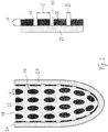
- Figure 1 shows in the left representation a liner 1 with a radial section along the longitudinal extent in which only the sectional plane is shown.
- the liner 1 is as formed closed liner and has a closed, distal end and an entry opening 18, via which a stump of a limb (not shown) can be introduced into the liner 1.
- the liner 1 has a base body 10 made of a flexible, water-impermeable and advantageously elastic material.
- the base body 10 has an inside 14 facing the stump in the applied state and an outside 12 facing away from the skin surface.
- the outer side 12 is designed to be closed, so that no moisture can penetrate from the stump through the base body 10 or reach the stump through the base body 10. Silicone or a plastic, for example polyurethane, can be used as the material for the base body 10.
- a large number of similar knobs 16 are formed on the inner side 14 of the base body 10, which protrude beyond the base body 10 in the direction of the skin surface.
- a coating 20 is applied, which consists of a material that is different from the material of the base body 10.
- the knobs 16, which have a flat surface 28 facing towards the skin surface, allow ventilation of the skin surface in those areas where the knobs 16 do not rest on the skin surface. This makes it possible to transport moisture and heat away from the liner 1 along the skin surface, so that warm air and moisture can escape at the distal edge 24 of the liner.
- the base body 10 and the knobs 16 protruding therefrom and directed towards the inside can be seen.
- the knobs 16 have a flat surface 28 and a knob height H which is smaller than the knob length L.
- the ratio of knob length L to knob height H is between 1.5 and 2.5, it being found to be more advantageous if the knob length L is in a range between 0.7 mm and 1.2 mm.
- the distances D between two knobs 16 are advantageously less than the knob height H and in the illustrated embodiment are approximately half the knob height. It can also be that the distances are chosen to be larger, so that the distance D between two knobs 16 can be up to 1.5 times the knob height H.
- the distance can be between 0.2mm and 1.2mm.
- FIG. 2 is an alternative representation of the liner 1 according to FIG Figure 1 shown.
- the shape of the knobs 16 is oval, the distance D is the smallest distance between two knobs 16, the knob length L denotes the larger longitudinal extent, the knob width B the smaller extent of the knobs 16.
- the ratio of knob length to knob width can be between 1 and 2.5.
- the arrangement of the knobs 16 runs essentially uniformly over the entire inside 14 of the base body 10, with inwardly open, interrupted channels 22 being formed between the knobs 16, which run essentially from distal to proximal and at the same time due to the arrangement of the knobs 16 Form circumferential channels at the same height, which intersect with the channels 22 in the proximal-distal direction, so that a free passage of heat and moisture from all parts of the body not covered by knob surfaces 28 to the proximal edge 22 is possible. The escape of heat and moisture takes place in the space between the base body 10 and the skin surface.
- the coating 22 is made of a material different from the material of the base body 10, the base body 10 and the knobs 16 are formed in one piece or in one piece and have good adhesion when placed on the skin.
- the outside coating 20 can be selected from a material that has particularly good mechanical properties and good durability, which does not necessarily have to coincide with skin compatibility, so that there is great freedom for the design of the liner 1 due to the use of two different materials.
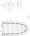
- FIG Figure 3 shows a radial section analogous to FIG Figure 1 In the illustration on the right it is clear that the entire liner 1 is made from a single material and the knobs 16 are formed in one piece on the inside 14 of the base body 10.
- FIG. 4 A variant of the Figure 3 is in the Figure 4 shown, in which the knob shape according to Figure 2 corresponds, the knobs 16 and the base body 10 are not formed in one piece, but are attached to the base body 10 afterwards were, for example, by gluing or by subsequent networking and material connection.
- the liner 1 according to Figure 4 provides for the use of only one material.
- the subsequent application of the knobs 16 can cover a greater range of variation in the manufacture of liners, since individual peculiarities can be taken into account.
- FIG. 5 is a cross section through a liner 1 according to Figure 1 shown perpendicular to the longitudinal extension.
- the uniform arrangement of the knobs 16 on the inside 14 of the base body 10 results in the channels 22
- Figure 5 shows the closed cross section of the liner 1, so that the liner 1 can completely enclose the stump, not shown.
- the knob height H is equal to the knob width B equal to the distance D between two knobs 16 and thus also the width of the channels 22.
- FIG Figure 6 shows an alternative representation of the liner 1 according to FIG Figure 6 , in which the arrangement of the knobs 16 can be seen better.
- the knobs 16 extend along the essentially cylindrical side wall of the base body 10 as well as in the conically tapering distal end region, with no knobs 16 being provided at the lowest point of the liner.
- Figure 7 shows a cross-sectional representation of a liner according to Figure 3
- Figure 8 a cross section through a liner according to Figure 4 .
- the difference of the embodiments according to Figures 7 and 8th consists in that the base body 10 has no coating on the outside 12.
- the material of the knobs 16 in the embodiment of FIG Figures 4 and 8th can also differ from the material of the base body 10.
- FIG. 9 a plan view of the inside 14 of a base body 10 with different knob shapes is shown.
- the left representation provides oval knobs 16, the right representation rectangular knobs 16.
- the knobs 16 run essentially parallel, in the left representation the knobs are offset in height so that diagonally running channels 22 Form next to the parallel running channels 22, in the right illustration the knobs 16 on the base body 10 are uniform distributed and run parallel to each other.
- the base body 10 can be provided with closure or fastening elements, not shown, so that it can be wrapped around a stump or a limb and attached to it, so that a liner that is open at the distal edge 26 and at the proximal edge 24 is created, which acts as an interface for a prosthetic or orthotic fitting can serve.
- closure or fastening elements not shown
- the knobs in the embodiment according to Figure 9 can be formed from a material different from the base body 10.
- Figure 10 is the plan view of the base body according to Figure 9 shown with knobs 16 made of the same material as the base body 10.
- the knobs 16 according to Figure 10 can be molded on during the primary forming process of the base body 10 or applied subsequently.
- the knobs 16 on both base bodies 10 form a structured surface with alternating elevations and depressions, so that air can circulate and moisture can be removed in the spaces between the knobs.
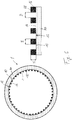
- the liner 1 is shown in a radial section with a base body 10 and an outer side 12.
- the insertion opening 18 on the distal edge 24 enables the liner 1 to be turned over and entered.
- webs 16 ' are provided which extend radially inward, so that channels 22 are formed between the webs 16' extend from the closed distal end to the open proximal rim 24.
- the channels 22 are oriented essentially in a straight line on the inside of the base body 10 and allow a direct removal of sweat and an exchange of air.
- the base body 10 is designed with closed walls and essentially impermeable to water.
- Figure 12 shows a detailed representation of the liner 1 with the base body 10 and the web 16 'protruding radially inward.
- the height H of the web 16 ' is dimensioned such that, on the one hand, there is sufficiently high stability against deformation when a compressive force is applied and, on the other hand, there is a sufficient distance between the inside of the base body 10 and the not shown Skin surface is provided to allow the removal of air and moisture.
- Figure 13 shows a cross section through the liner 1, from the figure it can be seen that the liner 1 has an essentially circular cross section and a closed structure of the base body 10.
- the projections formed as webs 16 ' which protrude radially inward from the inside 14 of the base body 10, run from the proximal edge to the distal tip.
- the channels 22 are formed between the webs 16 'in order to transport away air and moisture.
- a sectional view is in the Figure 14 from which it can be seen that the height H and the width B of the webs 16 'essentially correspond to one another, so that a square cross-section, starting from the base body 10, results for the web 16'.
- the distance D between two webs 16 'corresponds essentially to the width B of the web 16', a possible range of dimensions for the height H, the width B and the distance D is between 0.3 and 0.7 mm, but is not restricted to this .
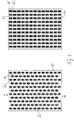
- Figure 15 shows a first variant of the inside of a liner in a plan view, in which, in addition to knobs 16 of different sizes and orientations, webs 16 ′ are applied or formed in oval shape on the base body 10.
- the channels 22 are formed between the webs 16 ′ and knobs 16.
- the Figure 15 it can be seen that the webs 16 'do not have to run continuously from the distal to the proximal end; rather, interruptions are also possible.
- a knob 16 is arranged between two web sections 16 '. In principle, it is possible to arrange knobs 16 and webs 16 ′ of different sizes and orientations on the inside of the base body 10.
- FIG. 16 Another variant is in the Figure 16 shown, in which a plurality of webs 16 'are arranged uniformly spaced from one another on the inside of the base body 10. Correspondingly uniform, rectilinear channels 22 are formed between the webs 16 '.
Landscapes
- Health & Medical Sciences (AREA)
- Cardiology (AREA)
- Oral & Maxillofacial Surgery (AREA)
- Transplantation (AREA)
- Engineering & Computer Science (AREA)
- Biomedical Technology (AREA)
- Heart & Thoracic Surgery (AREA)
- Vascular Medicine (AREA)
- Life Sciences & Earth Sciences (AREA)
- Animal Behavior & Ethology (AREA)
- General Health & Medical Sciences (AREA)
- Public Health (AREA)
- Veterinary Medicine (AREA)
- Orthopedics, Nursing, And Contraception (AREA)
- Prostheses (AREA)
Claims (14)
- Doublure pour l'application sur une surface épidermique, comportant un corps de base (10) en un matériau flexible, imperméable à l'eau, ayant une face extérieure (12) détournée de la surface épidermique à l'état appliqué et une face intérieure (14) tournée vers la surface épidermique à l'état appliqué,
dans laquelle
le corps de base (10) présente une face extérieure fermée (12), et des canaux (22) ouverts vers la surface épidermique sont disposés sur la face intérieure (14), le long desquels sont évacuées l'humidité et la chaleur, les canaux (22) étant formés par des bosses (16) et/ou par des barrettes (16'), et les bosses (16) et/ou les barrettes (16') étant réalisées d'un seul tenant avec le corps de base. - Doublure selon la revendication 1,
dans laquelle le corps de base (10) présente une section transversale fermée ayant une ouverture d'accès proximale (18). - Doublure selon l'une des revendications précédentes,
dans laquelle un revêtement (20) en un matériau différent du matériau du corps de base (10) est appliqué sur la face extérieure (12). - Doublure selon l'une des revendications précédentes,
dans laquelle en ce que les bosses (16) et/ou les barrettes (16') sont disposées en une disposition régulière sur la face intérieure (14). - Doublure selon l'une des revendications précédentes,
dans laquelle les bosses (16) et/ou les barrettes (16') sont disposées sur toute la face intérieure (14). - Doublure selon l'une des revendications précédentes,
dans laquelle les bosses (16) et/ou les barrettes (16') ont une surface plane (28) dirigée vers la surface épidermique. - Doublure selon l'une des revendications précédentes,
dans laquelle le rapport de la longueur (L) sur la largeur (B) de la bosse est compris entre 0,8 et 2,5, et/ou le rapport de la longueur (L) sur la hauteur (H) de la bosse est compris entre 1,5 et 2,5. - Doublure selon l'une des revendications précédentes,
dans laquelle la distance (D) entre deux bosses (16) et/ou barrettes (16') est comprise entre la moitié de la hauteur (H) de la bosse ou de la barrette et 1,5 fois la hauteur (H) de la bosse ou de la barrette. - Doublure selon l'une des revendications précédentes,
dans laquelle le rapport de la hauteur (H) de la bosse ou de la barrette sur la largeur (B) de la bosse ou de la barrette est inférieur à 1. - Doublure selon l'une des revendications précédentes,
dans laquelle les canaux (22) s'étendent jusqu'à un bord proximal ou distal (24, 26) et/ou sont réalisés sous forme de canaux d'aspiration ou de ventilation. - Doublure selon l'une des revendications précédentes,
dans laquelle il est prévu au moins un dispositif de raccordement pour un dispositif de ventilation. - Doublure selon l'une des revendications précédentes,
dans laquelle un raccord pour l'aération ou la ventilation est disposé dans la doublure, qui est en liaison fluidique avec les canaux (22). - Doublure selon l'une des revendications précédentes,
dans laquelle un matériau à changement de phase est disposé sur la doublure ou est intégré dans la doublure. - Doublure selon la revendication 13,
dans laquelle les canaux (22) sont en liaison fluidique avec un matériau à changement de phase.
Applications Claiming Priority (2)
| Application Number | Priority Date | Filing Date | Title |
|---|---|---|---|
| DE102014011374.4A DE102014011374A1 (de) | 2014-08-05 | 2014-08-05 | Liner |
| PCT/EP2015/067800 WO2016020317A1 (fr) | 2014-08-05 | 2015-08-03 | Garniture |
Publications (2)
| Publication Number | Publication Date |
|---|---|
| EP3177236A1 EP3177236A1 (fr) | 2017-06-14 |
| EP3177236B1 true EP3177236B1 (fr) | 2020-12-16 |
Family
ID=53785632
Family Applications (1)
| Application Number | Title | Priority Date | Filing Date |
|---|---|---|---|
| EP15747788.6A Active EP3177236B1 (fr) | 2014-08-05 | 2015-08-03 | Manchon |
Country Status (4)
| Country | Link |
|---|---|
| US (1) | US20170202687A1 (fr) |
| EP (1) | EP3177236B1 (fr) |
| DE (1) | DE102014011374A1 (fr) |
| WO (1) | WO2016020317A1 (fr) |
Families Citing this family (5)
| Publication number | Priority date | Publication date | Assignee | Title |
|---|---|---|---|---|
| US10842653B2 (en) | 2007-09-19 | 2020-11-24 | Ability Dynamics, Llc | Vacuum system for a prosthetic foot |
| EP3261587B1 (fr) | 2015-02-26 | 2019-11-13 | Andreas Radspieler | Dispositif, kit et procédé de production d'une empreinte en plâtre d'un moignon de membre d'un patient pour la fabrication d'une tige de prothèse, ainsi qu'adaptateur |
| DE102018131550A1 (de) * | 2018-12-10 | 2020-06-10 | Ottobock Se & Co. Kgaa | Orthopädietechnische Einrichtung |
| US11602445B2 (en) * | 2019-05-07 | 2023-03-14 | Alps South Europe, S.R.O. | Silicone liner |
| DE102019118422B3 (de) * | 2019-07-08 | 2021-01-07 | Otto Bock Healthcare Products Gmbh | Aktuator und Wärmespeicher für Aktuator |
Family Cites Families (24)
| Publication number | Priority date | Publication date | Assignee | Title |
|---|---|---|---|---|
| DE3820098A1 (de) * | 1988-06-13 | 1989-12-14 | Gore W L & Co Gmbh | Orthopaedische koerperhilfsvorrichtung |
| FI79021C (fi) * | 1988-09-28 | 1989-11-10 | Martti J O Filppula | PROTES. SIIRRETTY PAEIVAEMAEAERAE-FOERSKJUTET DATUM PL 14 ç 10.10.88 |
| US5156629A (en) * | 1990-03-15 | 1992-10-20 | Shane Mark D | Pneumatic prosthetic insert |
| US6964688B1 (en) * | 1996-07-31 | 2005-11-15 | Ohio Willow Wood Company | Tube sock-shaped covering |
| US5980577A (en) * | 1997-05-01 | 1999-11-09 | Radis; Vasilis | Protective item supporting an appendage |
| US20010016781A1 (en) | 1999-06-03 | 2001-08-23 | Caspers Carl A. | Osmotic membrane and vacuum system for artificial limb |
| US6440172B1 (en) * | 1999-09-16 | 2002-08-27 | Rx Textiles | Reinforced prosthetic sleeve |
| DE10153796B4 (de) | 2001-11-05 | 2005-10-13 | össur h.f. | Prothesenschaft mit Dichtung am distalen Ende |
| US7909884B2 (en) | 2002-12-20 | 2011-03-22 | Ossur Hf | Suspension liner system with seal |
| US8182547B2 (en) | 2005-09-08 | 2012-05-22 | Charles King | Negative gauge pressure moisture management and secure adherence artificial limb system and associated methods |
| US8270305B2 (en) * | 2007-03-06 | 2012-09-18 | Nec Corporation | Node device, node system, and method and program for changing statistic information management table used for the node device |
| EP2170229A2 (fr) * | 2007-08-02 | 2010-04-07 | Össur HF | Revêtement de systèmes prothétiques et orthopédiques |
| US20090182435A1 (en) * | 2008-01-15 | 2009-07-16 | Engineered Silicone Products, Llc | Limb prosthesis |
| EP2429458A4 (fr) * | 2009-04-28 | 2015-03-25 | Cadence Biomedical Inc | Prothèse ajustable |
| US8282686B2 (en) | 2009-09-18 | 2012-10-09 | Lincolnshire Manufacturing LLC | Prosthetic socket |
| JP5503274B2 (ja) * | 2009-12-11 | 2014-05-28 | 中村ブレイス株式会社 | 義足用インナーバッグ |
| EP2353550A1 (fr) * | 2010-02-05 | 2011-08-10 | Nakamura Brace Co.,Ltd. | Élément pour membre artificiel |
| US8668744B2 (en) | 2010-09-29 | 2014-03-11 | Blatchford Products Limited | Suspension device for a limb prosthesis or orthosis |
| US9248032B2 (en) | 2010-10-14 | 2016-02-02 | Ossur Hf | Suspension liner system with distensible seal |
| US9358138B2 (en) * | 2012-07-23 | 2016-06-07 | The Ohio Willow Wood Company | Polymeric prosthetic devices with heat control capabilities |
| WO2014142643A1 (fr) * | 2013-03-13 | 2014-09-18 | Universiti Malaya | Doublure pour prothèse de membre |
| WO2014205403A1 (fr) * | 2013-06-21 | 2014-12-24 | Lim Innovations, Inc. | Emboîture de prothèse et revêtement d'emboîture avec fonction de régulation de l'humidité |
| US20160184113A1 (en) * | 2014-03-19 | 2016-06-30 | Wayne A. Koniuk | Limb socket liner with seal |
| DE102014011034B4 (de) * | 2014-07-23 | 2016-06-23 | Uniprox GmbH & Co. KG | Perforierter Liner |
-
2014
- 2014-08-05 DE DE102014011374.4A patent/DE102014011374A1/de active Pending
-
2015
- 2015-08-03 US US15/326,823 patent/US20170202687A1/en not_active Abandoned
- 2015-08-03 EP EP15747788.6A patent/EP3177236B1/fr active Active
- 2015-08-03 WO PCT/EP2015/067800 patent/WO2016020317A1/fr active Application Filing
Non-Patent Citations (1)
| Title |
|---|
| None * |
Also Published As
| Publication number | Publication date |
|---|---|
| EP3177236A1 (fr) | 2017-06-14 |
| WO2016020317A1 (fr) | 2016-02-11 |
| DE102014011374A1 (de) | 2016-02-11 |
| US20170202687A1 (en) | 2017-07-20 |
Similar Documents
| Publication | Publication Date | Title |
|---|---|---|
| EP3177236B1 (fr) | Manchon | |
| EP4108213B1 (fr) | Liner prothétique | |
| EP3238667B1 (fr) | Enveloppe destinee a recouvrir un moignon | |
| EP2890335B1 (fr) | Manchon prothétique et système d'emboîture de prothèse comprenant un manchon et une emboîture | |
| WO2020069817A1 (fr) | Procédé de fabrication d'un dispositif de technique orthopédique et dispositif de technique orthopédique | |
| WO2016020244A1 (fr) | Interface et système constitué d'une interface et d'une orthèse ou d'une prothèse | |
| DE102012022484B4 (de) | Prothesenliner | |
| EP3171827B1 (fr) | Manchon perforé | |
| EP2944290B1 (fr) | Enveloppe de prothèse | |
| EP3614977B1 (fr) | Système de revêtement et procédé servant à poser un système de revêtement | |
| DE3820098A1 (de) | Orthopaedische koerperhilfsvorrichtung | |
| EP3171826B1 (fr) | Garniture pour prothèse | |
| EP1941817A1 (fr) | Couverture chauffante | |
| WO1995003760A1 (fr) | Membre artificiel | |
| EP3727539A1 (fr) | Dispositif de trachéostomie | |
| EP3886771B1 (fr) | Palette en matière plastique comprenant des éléments de renforcement | |
| EP3975941A1 (fr) | Procédé de fabrication d'un manchon de prothèse et système comprenant un manchon de prothèse et une emboîture de prothèse | |
| WO2011131718A1 (fr) | Dispositif de refroidissement | |
| DE102016107074A1 (de) | Vorrichtung, Positioniervorrichtung und Verfahren zum Erstellen eines Gipsabdrucks eines Körpergliedstumpfs eines Patienten | |
| WO2023170090A1 (fr) | Kit ayant un dispositif pour créer une tige de prothèse à partir d'un matériau de résine durcissant aux uv, et procédé | |
| DE102010026724A1 (de) | Vorrichtung zum Halten innerer Organe und/oder eines Wundrandes während einer invasiven Operation | |
| DE202006016325U1 (de) | Vorrichtung zum Auspolstern von insbesondere orthetischen oder prothetischen Hilfsmitteln und einem mit dieser Vorrichtung versehenen Hilfsmittel |
Legal Events
| Date | Code | Title | Description |
|---|---|---|---|
| STAA | Information on the status of an ep patent application or granted ep patent |
Free format text: STATUS: THE INTERNATIONAL PUBLICATION HAS BEEN MADE |
|
| PUAI | Public reference made under article 153(3) epc to a published international application that has entered the european phase |
Free format text: ORIGINAL CODE: 0009012 |
|
| STAA | Information on the status of an ep patent application or granted ep patent |
Free format text: STATUS: REQUEST FOR EXAMINATION WAS MADE |
|
| 17P | Request for examination filed |
Effective date: 20170222 |
|
| AK | Designated contracting states |
Kind code of ref document: A1 Designated state(s): AL AT BE BG CH CY CZ DE DK EE ES FI FR GB GR HR HU IE IS IT LI LT LU LV MC MK MT NL NO PL PT RO RS SE SI SK SM TR |
|
| AX | Request for extension of the european patent |
Extension state: BA ME |
|
| DAV | Request for validation of the european patent (deleted) | ||
| DAX | Request for extension of the european patent (deleted) | ||
| RAP1 | Party data changed (applicant data changed or rights of an application transferred) |
Owner name: OTTOBOCK SE & CO. KGAA |
|
| STAA | Information on the status of an ep patent application or granted ep patent |
Free format text: STATUS: EXAMINATION IS IN PROGRESS |
|
| 17Q | First examination report despatched |
Effective date: 20190313 |
|
| GRAP | Despatch of communication of intention to grant a patent |
Free format text: ORIGINAL CODE: EPIDOSNIGR1 |
|
| STAA | Information on the status of an ep patent application or granted ep patent |
Free format text: STATUS: GRANT OF PATENT IS INTENDED |
|
| INTG | Intention to grant announced |
Effective date: 20200707 |
|
| GRAS | Grant fee paid |
Free format text: ORIGINAL CODE: EPIDOSNIGR3 |
|
| GRAA | (expected) grant |
Free format text: ORIGINAL CODE: 0009210 |
|
| STAA | Information on the status of an ep patent application or granted ep patent |
Free format text: STATUS: THE PATENT HAS BEEN GRANTED |
|
| AK | Designated contracting states |
Kind code of ref document: B1 Designated state(s): AL AT BE BG CH CY CZ DE DK EE ES FI FR GB GR HR HU IE IS IT LI LT LU LV MC MK MT NL NO PL PT RO RS SE SI SK SM TR |
|
| REG | Reference to a national code |
Ref country code: GB Ref legal event code: FG4D Free format text: NOT ENGLISH |
|
| REG | Reference to a national code |
Ref country code: IE Ref legal event code: FG4D Free format text: LANGUAGE OF EP DOCUMENT: GERMAN |
|
| REG | Reference to a national code |
Ref country code: DE Ref legal event code: R096 Ref document number: 502015014020 Country of ref document: DE |
|
| REG | Reference to a national code |
Ref country code: AT Ref legal event code: REF Ref document number: 1344890 Country of ref document: AT Kind code of ref document: T Effective date: 20210115 |
|
| PG25 | Lapsed in a contracting state [announced via postgrant information from national office to epo] |
Ref country code: GR Free format text: LAPSE BECAUSE OF FAILURE TO SUBMIT A TRANSLATION OF THE DESCRIPTION OR TO PAY THE FEE WITHIN THE PRESCRIBED TIME-LIMIT Effective date: 20210317 Ref country code: RS Free format text: LAPSE BECAUSE OF FAILURE TO SUBMIT A TRANSLATION OF THE DESCRIPTION OR TO PAY THE FEE WITHIN THE PRESCRIBED TIME-LIMIT Effective date: 20201216 Ref country code: FI Free format text: LAPSE BECAUSE OF FAILURE TO SUBMIT A TRANSLATION OF THE DESCRIPTION OR TO PAY THE FEE WITHIN THE PRESCRIBED TIME-LIMIT Effective date: 20201216 Ref country code: NO Free format text: LAPSE BECAUSE OF FAILURE TO SUBMIT A TRANSLATION OF THE DESCRIPTION OR TO PAY THE FEE WITHIN THE PRESCRIBED TIME-LIMIT Effective date: 20210316 |
|
| REG | Reference to a national code |
Ref country code: NL Ref legal event code: MP Effective date: 20201216 |
|
| PG25 | Lapsed in a contracting state [announced via postgrant information from national office to epo] |
Ref country code: SE Free format text: LAPSE BECAUSE OF FAILURE TO SUBMIT A TRANSLATION OF THE DESCRIPTION OR TO PAY THE FEE WITHIN THE PRESCRIBED TIME-LIMIT Effective date: 20201216 Ref country code: LV Free format text: LAPSE BECAUSE OF FAILURE TO SUBMIT A TRANSLATION OF THE DESCRIPTION OR TO PAY THE FEE WITHIN THE PRESCRIBED TIME-LIMIT Effective date: 20201216 Ref country code: BG Free format text: LAPSE BECAUSE OF FAILURE TO SUBMIT A TRANSLATION OF THE DESCRIPTION OR TO PAY THE FEE WITHIN THE PRESCRIBED TIME-LIMIT Effective date: 20210316 |
|
| PG25 | Lapsed in a contracting state [announced via postgrant information from national office to epo] |
Ref country code: NL Free format text: LAPSE BECAUSE OF FAILURE TO SUBMIT A TRANSLATION OF THE DESCRIPTION OR TO PAY THE FEE WITHIN THE PRESCRIBED TIME-LIMIT Effective date: 20201216 Ref country code: HR Free format text: LAPSE BECAUSE OF FAILURE TO SUBMIT A TRANSLATION OF THE DESCRIPTION OR TO PAY THE FEE WITHIN THE PRESCRIBED TIME-LIMIT Effective date: 20201216 |
|
| REG | Reference to a national code |
Ref country code: LT Ref legal event code: MG9D |
|
| PG25 | Lapsed in a contracting state [announced via postgrant information from national office to epo] |
Ref country code: PT Free format text: LAPSE BECAUSE OF FAILURE TO SUBMIT A TRANSLATION OF THE DESCRIPTION OR TO PAY THE FEE WITHIN THE PRESCRIBED TIME-LIMIT Effective date: 20210416 Ref country code: RO Free format text: LAPSE BECAUSE OF FAILURE TO SUBMIT A TRANSLATION OF THE DESCRIPTION OR TO PAY THE FEE WITHIN THE PRESCRIBED TIME-LIMIT Effective date: 20201216 Ref country code: SK Free format text: LAPSE BECAUSE OF FAILURE TO SUBMIT A TRANSLATION OF THE DESCRIPTION OR TO PAY THE FEE WITHIN THE PRESCRIBED TIME-LIMIT Effective date: 20201216 Ref country code: LT Free format text: LAPSE BECAUSE OF FAILURE TO SUBMIT A TRANSLATION OF THE DESCRIPTION OR TO PAY THE FEE WITHIN THE PRESCRIBED TIME-LIMIT Effective date: 20201216 Ref country code: SM Free format text: LAPSE BECAUSE OF FAILURE TO SUBMIT A TRANSLATION OF THE DESCRIPTION OR TO PAY THE FEE WITHIN THE PRESCRIBED TIME-LIMIT Effective date: 20201216 Ref country code: EE Free format text: LAPSE BECAUSE OF FAILURE TO SUBMIT A TRANSLATION OF THE DESCRIPTION OR TO PAY THE FEE WITHIN THE PRESCRIBED TIME-LIMIT Effective date: 20201216 Ref country code: CZ Free format text: LAPSE BECAUSE OF FAILURE TO SUBMIT A TRANSLATION OF THE DESCRIPTION OR TO PAY THE FEE WITHIN THE PRESCRIBED TIME-LIMIT Effective date: 20201216 |
|
| PG25 | Lapsed in a contracting state [announced via postgrant information from national office to epo] |
Ref country code: PL Free format text: LAPSE BECAUSE OF FAILURE TO SUBMIT A TRANSLATION OF THE DESCRIPTION OR TO PAY THE FEE WITHIN THE PRESCRIBED TIME-LIMIT Effective date: 20201216 |
|
| REG | Reference to a national code |
Ref country code: DE Ref legal event code: R097 Ref document number: 502015014020 Country of ref document: DE |
|
| PG25 | Lapsed in a contracting state [announced via postgrant information from national office to epo] |
Ref country code: IS Free format text: LAPSE BECAUSE OF FAILURE TO SUBMIT A TRANSLATION OF THE DESCRIPTION OR TO PAY THE FEE WITHIN THE PRESCRIBED TIME-LIMIT Effective date: 20210416 |
|
| PLBE | No opposition filed within time limit |
Free format text: ORIGINAL CODE: 0009261 |
|
| STAA | Information on the status of an ep patent application or granted ep patent |
Free format text: STATUS: NO OPPOSITION FILED WITHIN TIME LIMIT |
|
| PG25 | Lapsed in a contracting state [announced via postgrant information from national office to epo] |
Ref country code: IT Free format text: LAPSE BECAUSE OF FAILURE TO SUBMIT A TRANSLATION OF THE DESCRIPTION OR TO PAY THE FEE WITHIN THE PRESCRIBED TIME-LIMIT Effective date: 20201216 Ref country code: AL Free format text: LAPSE BECAUSE OF FAILURE TO SUBMIT A TRANSLATION OF THE DESCRIPTION OR TO PAY THE FEE WITHIN THE PRESCRIBED TIME-LIMIT Effective date: 20201216 |
|
| 26N | No opposition filed |
Effective date: 20210917 |
|
| PG25 | Lapsed in a contracting state [announced via postgrant information from national office to epo] |
Ref country code: DK Free format text: LAPSE BECAUSE OF FAILURE TO SUBMIT A TRANSLATION OF THE DESCRIPTION OR TO PAY THE FEE WITHIN THE PRESCRIBED TIME-LIMIT Effective date: 20201216 |
|
| PG25 | Lapsed in a contracting state [announced via postgrant information from national office to epo] |
Ref country code: ES Free format text: LAPSE BECAUSE OF FAILURE TO SUBMIT A TRANSLATION OF THE DESCRIPTION OR TO PAY THE FEE WITHIN THE PRESCRIBED TIME-LIMIT Effective date: 20201216 |
|
| PG25 | Lapsed in a contracting state [announced via postgrant information from national office to epo] |
Ref country code: SI Free format text: LAPSE BECAUSE OF FAILURE TO SUBMIT A TRANSLATION OF THE DESCRIPTION OR TO PAY THE FEE WITHIN THE PRESCRIBED TIME-LIMIT Effective date: 20201216 |
|
| REG | Reference to a national code |
Ref country code: CH Ref legal event code: PL |
|
| PG25 | Lapsed in a contracting state [announced via postgrant information from national office to epo] |
Ref country code: MC Free format text: LAPSE BECAUSE OF FAILURE TO SUBMIT A TRANSLATION OF THE DESCRIPTION OR TO PAY THE FEE WITHIN THE PRESCRIBED TIME-LIMIT Effective date: 20201216 |
|
| REG | Reference to a national code |
Ref country code: BE Ref legal event code: MM Effective date: 20210831 |
|
| PG25 | Lapsed in a contracting state [announced via postgrant information from national office to epo] |
Ref country code: LI Free format text: LAPSE BECAUSE OF NON-PAYMENT OF DUE FEES Effective date: 20210831 Ref country code: CH Free format text: LAPSE BECAUSE OF NON-PAYMENT OF DUE FEES Effective date: 20210831 |
|
| PG25 | Lapsed in a contracting state [announced via postgrant information from national office to epo] |
Ref country code: IS Free format text: LAPSE BECAUSE OF FAILURE TO SUBMIT A TRANSLATION OF THE DESCRIPTION OR TO PAY THE FEE WITHIN THE PRESCRIBED TIME-LIMIT Effective date: 20210416 Ref country code: LU Free format text: LAPSE BECAUSE OF NON-PAYMENT OF DUE FEES Effective date: 20210803 |
|
| PG25 | Lapsed in a contracting state [announced via postgrant information from national office to epo] |
Ref country code: IE Free format text: LAPSE BECAUSE OF NON-PAYMENT OF DUE FEES Effective date: 20210803 Ref country code: BE Free format text: LAPSE BECAUSE OF NON-PAYMENT OF DUE FEES Effective date: 20210831 |
|
| REG | Reference to a national code |
Ref country code: AT Ref legal event code: MM01 Ref document number: 1344890 Country of ref document: AT Kind code of ref document: T Effective date: 20210803 |
|
| PG25 | Lapsed in a contracting state [announced via postgrant information from national office to epo] |
Ref country code: AT Free format text: LAPSE BECAUSE OF NON-PAYMENT OF DUE FEES Effective date: 20210803 |
|
| PG25 | Lapsed in a contracting state [announced via postgrant information from national office to epo] |
Ref country code: HU Free format text: LAPSE BECAUSE OF FAILURE TO SUBMIT A TRANSLATION OF THE DESCRIPTION OR TO PAY THE FEE WITHIN THE PRESCRIBED TIME-LIMIT; INVALID AB INITIO Effective date: 20150803 |
|
| PG25 | Lapsed in a contracting state [announced via postgrant information from national office to epo] |
Ref country code: CY Free format text: LAPSE BECAUSE OF FAILURE TO SUBMIT A TRANSLATION OF THE DESCRIPTION OR TO PAY THE FEE WITHIN THE PRESCRIBED TIME-LIMIT Effective date: 20201216 |
|
| PGFP | Annual fee paid to national office [announced via postgrant information from national office to epo] |
Ref country code: GB Payment date: 20230824 Year of fee payment: 9 |
|
| PGFP | Annual fee paid to national office [announced via postgrant information from national office to epo] |
Ref country code: FR Payment date: 20230821 Year of fee payment: 9 Ref country code: DE Payment date: 20230822 Year of fee payment: 9 |
|
| PG25 | Lapsed in a contracting state [announced via postgrant information from national office to epo] |
Ref country code: MK Free format text: LAPSE BECAUSE OF FAILURE TO SUBMIT A TRANSLATION OF THE DESCRIPTION OR TO PAY THE FEE WITHIN THE PRESCRIBED TIME-LIMIT Effective date: 20201216 |