EP3176096B1 - Vorrichtung und entsprechendes verfahren - Google Patents
Vorrichtung und entsprechendes verfahren Download PDFInfo
- Publication number
- EP3176096B1 EP3176096B1 EP15197754.3A EP15197754A EP3176096B1 EP 3176096 B1 EP3176096 B1 EP 3176096B1 EP 15197754 A EP15197754 A EP 15197754A EP 3176096 B1 EP3176096 B1 EP 3176096B1
- Authority
- EP
- European Patent Office
- Prior art keywords
- holding liquid
- carrier tape
- electronic component
- tape
- Prior art date
- Legal status (The legal status is an assumption and is not a legal conclusion. Google has not performed a legal analysis and makes no representation as to the accuracy of the status listed.)
- Active
Links
Images
Classifications
-
- B—PERFORMING OPERATIONS; TRANSPORTING
- B65—CONVEYING; PACKING; STORING; HANDLING THIN OR FILAMENTARY MATERIAL
- B65B—MACHINES, APPARATUS OR DEVICES FOR, OR METHODS OF, PACKAGING ARTICLES OR MATERIALS; UNPACKING
- B65B15/00—Attaching articles to cards, sheets, strings, webs, or other carriers
- B65B15/04—Attaching a series of articles, e.g. small electrical components, to a continuous web
-
- H—ELECTRICITY
- H10—SEMICONDUCTOR DEVICES; ELECTRIC SOLID-STATE DEVICES NOT OTHERWISE PROVIDED FOR
- H10P—GENERIC PROCESSES OR APPARATUS FOR THE MANUFACTURE OR TREATMENT OF DEVICES COVERED BY CLASS H10
- H10P72/00—Handling or holding of wafers, substrates or devices during manufacture or treatment thereof
- H10P72/70—Handling or holding of wafers, substrates or devices during manufacture or treatment thereof for supporting or gripping
- H10P72/74—Handling or holding of wafers, substrates or devices during manufacture or treatment thereof for supporting or gripping using temporarily an auxiliary support
- H10P72/7402—Wafer tapes, e.g. grinding or dicing support tapes
-
- B—PERFORMING OPERATIONS; TRANSPORTING
- B65—CONVEYING; PACKING; STORING; HANDLING THIN OR FILAMENTARY MATERIAL
- B65B—MACHINES, APPARATUS OR DEVICES FOR, OR METHODS OF, PACKAGING ARTICLES OR MATERIALS; UNPACKING
- B65B9/00—Enclosing successive articles, or quantities of material, e.g. liquids or semiliquids, in flat, folded, or tubular webs of flexible sheet material; Subdividing filled flexible tubes to form packages
- B65B9/02—Enclosing successive articles, or quantities of material between opposed webs
- B65B9/04—Enclosing successive articles, or quantities of material between opposed webs one or both webs being formed with pockets for the reception of the articles, or of the quantities of material
-
- B—PERFORMING OPERATIONS; TRANSPORTING
- B65—CONVEYING; PACKING; STORING; HANDLING THIN OR FILAMENTARY MATERIAL
- B65B—MACHINES, APPARATUS OR DEVICES FOR, OR METHODS OF, PACKAGING ARTICLES OR MATERIALS; UNPACKING
- B65B9/00—Enclosing successive articles, or quantities of material, e.g. liquids or semiliquids, in flat, folded, or tubular webs of flexible sheet material; Subdividing filled flexible tubes to form packages
- B65B9/02—Enclosing successive articles, or quantities of material between opposed webs
- B65B9/04—Enclosing successive articles, or quantities of material between opposed webs one or both webs being formed with pockets for the reception of the articles, or of the quantities of material
- B65B9/042—Enclosing successive articles, or quantities of material between opposed webs one or both webs being formed with pockets for the reception of the articles, or of the quantities of material for fluent material
-
- B—PERFORMING OPERATIONS; TRANSPORTING
- B65—CONVEYING; PACKING; STORING; HANDLING THIN OR FILAMENTARY MATERIAL
- B65B—MACHINES, APPARATUS OR DEVICES FOR, OR METHODS OF, PACKAGING ARTICLES OR MATERIALS; UNPACKING
- B65B9/00—Enclosing successive articles, or quantities of material, e.g. liquids or semiliquids, in flat, folded, or tubular webs of flexible sheet material; Subdividing filled flexible tubes to form packages
- B65B9/02—Enclosing successive articles, or quantities of material between opposed webs
- B65B9/04—Enclosing successive articles, or quantities of material between opposed webs one or both webs being formed with pockets for the reception of the articles, or of the quantities of material
- B65B9/045—Enclosing successive articles, or quantities of material between opposed webs one or both webs being formed with pockets for the reception of the articles, or of the quantities of material for single articles, e.g. tablets
-
- H—ELECTRICITY
- H05—ELECTRIC TECHNIQUES NOT OTHERWISE PROVIDED FOR
- H05K—PRINTED CIRCUITS; CASINGS OR CONSTRUCTIONAL DETAILS OF ELECTRIC APPARATUS; MANUFACTURE OF ASSEMBLAGES OF ELECTRICAL COMPONENTS
- H05K13/00—Apparatus or processes specially adapted for manufacturing or adjusting assemblages of electric components
- H05K13/0084—Containers and magazines for components, e.g. tube-like magazines
-
- H—ELECTRICITY
- H10—SEMICONDUCTOR DEVICES; ELECTRIC SOLID-STATE DEVICES NOT OTHERWISE PROVIDED FOR
- H10P—GENERIC PROCESSES OR APPARATUS FOR THE MANUFACTURE OR TREATMENT OF DEVICES COVERED BY CLASS H10
- H10P72/00—Handling or holding of wafers, substrates or devices during manufacture or treatment thereof
- H10P72/30—Handling or holding of wafers, substrates or devices during manufacture or treatment thereof for conveying, e.g. between different workstations
- H10P72/32—Handling or holding of wafers, substrates or devices during manufacture or treatment thereof for conveying, e.g. between different workstations between different workstations
- H10P72/3218—Conveying cassettes, containers or carriers
Definitions
- the present disclosure relates to the field of tape packaging electronic components.
- the present disclosure relates to an apparatus and associated method for retaining an electrical component in a pocket of a carrier tape by way of a holding liquid placed within the pocket.
- One of the final steps of production of an electronic component may be placing the finished electronic component within a tape for use in tape and reel PCB assembly devices.
- each of a plurality of electronic components may be placed within each of a plurality of pockets formed at spaced locations within the tape.
- Each electronic components may then be closed within its respective pocket for distribution and transport, for example.
- US 5729963 A discloses an apparatus according to preamble of claim 1.
- the apparatus may comprise a controller for a tape packaging apparatus. Accordingly, the apparatus may provide signalling to control a tape packaging apparatus to provide for the above functions.
- the apparatus may comprise a tape packaging apparatus including means to perform the above functions.
- the apparatus may provide for evaporation of the holding liquid by heating the at least one closed pocket (the pocket closed by the sealing tape) or by reduction of the pressure outside the at least one closed pocket relative to the pressure inside the at least one closed pocket.
- the apparatus comprises a tape packaging apparatus and includes an indexing element to move the carrier tape through the apparatus, the indexing element configured to present the or each pocket of the carrier tape to a holding liquid transfer element of the apparatus to provide for transfer of the holding liquid to the pocket and, subsequently, to a pick and place head for placement of the electronic component into the pocket to contact the holding liquid placed therein by the holding liquid transfer element and, subsequently, to a sealing tape application element to provide for the application of the sealing tape over the carrier tape.
- the apparatus includes a holding liquid transfer element to provide for transfer of the holding liquid to the pocket.
- the holding liquid transfer element comprises a liquid dispensing head configured to align with the at least one pocket and dispense the holding liquid to provide for transfer of the holding liquid into the at least one pocket of the carrier tape.
- the liquid dispensing head is configured to print the holding liquid into the at least one pocket of the carrier tape.
- the liquid dispensing head is an ink jet type head.
- the apparatus includes a pick and place head configured to provide for placement of the electronic component into the at least one pocket.
- the apparatus is configured to receive the carrier tape including an aperture located in the at least one pocket that extends through the carrier tape, the apparatus including a liquid tray configured to present the holding liquid to the carrier tape, the apparatus configured to provide for dipping of the aperture of the at least one pocket into the holding liquid in the liquid tray thereby providing for the transfer of holding liquid into the pocket by capillary action through the aperture.
- the holding liquid transfer element in this embodiment, comprises the liquid tray and a dipping element to provide for the dipping of the aperture into the holding liquid in the tray.
- the evaporating may be provided by heating or pressure changes.
- the method includes transferring the holding liquid by one or more of;
- the holding liquid is transferred to a base of the pocket.
- the holding liquid is transferred to the pocket to only partially fill the pocket. In one or more embodiments, the holding liquid is transferred to the pocket to fill the pocket to less than 20% of the volume of the pocket. In one or more embodiments, the holding liquid fills the pocket to less than 10%, 8%, 6%, 4%, 2%, or 1% of the volume of the pocket. In one or more embodiments, the holding liquid fills the pocket to greater than 5%, 2%, or 1% of the volume of the pocket. Ranges of percentages may be formed from appropriate upper and lower bounds stated above.
- placing the electronic component comprises placing the electronic component directly onto the holding liquid present within the pocket.
- applying the sealing tape comprises placing the sealing tape over the carrier tape at a position that covers an open end of the at least one pocket and applying thermo-compression between the sealing tape and carrier tape.
- a computer program or computer program product comprising computer program code which when executed by a processor having a memory which causes a tape packaging apparatus to perform the method of the second aspect.
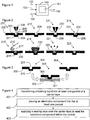
- Figure 1 shows, schematically, a tape packaging apparatus 100 having a controller 101 to provide for control of at least part of its operation.
- the controller 101 may comprise hardware, software or firmware.
- the controller may comprise a processor having memory on which computer program code is executed to provide signalling that controls elements of the tape packaging apparatus, as described below.
- the tape packaging apparatus 100 may receive, at 102, a carrier tape having a plurality of pockets therein and a sealing tape.
- the tape packaging apparatus 100 may receive, at 103, electronic components for placing within the plurality of pockets.
- the tape packaging apparatus 100 may receive, at 104, a supply of holding liquid for transfer into the plurality of pockets to hold the electronic components within the pockets during subsequent processing steps.
- the output of the apparatus 100 may comprise the carrier tape having an electronic component with each of the pockets and the pockets closed by the sealing tape.
- the apparatus 100 may include a heater to provide for evaporation of the holding liquid out of the closed pockets.
- Figure 2 schematically shows an example series of steps to provide for the tape packaging of electronic components using holding liquid.
- Figure 2 shows a carrier tape 200 in cross-section.
- the carrier tape 200 includes a plurality of pockets 201 formed therein for receiving electronic components 202.
- the pocket(s) comprise a recess within the carrier tape 200 that may be positioned at spaced locations along the carrier tape 200.
- the pockets 201 may comprise, as shown in Figure 2 , depressions in a major surface 203 of the carrier tape and may include a base 204 and side walls 205 between the base 204 and the major surface 203.
- the apparatus 100 includes a holding liquid transfer element to provide for transfer of a holding liquid into at least one pocket of a carrier tape.
- the holding liquid transfer element comprises a liquid dispensing head 206.
- the liquid dispensing head 206 is configured to align with each pocket 201 of the carrier tape 200 and dispense the holding liquid 208 into the pocket.
- the liquid dispensing head may be configured to print the holding fluid into each of the pockets.
- the liquid dispensing head may be an ink jet type head, although other printing heads may be used.
- the printing head may use a gaseous propellant, heat, hydraulic action or other means to dispense the holding fluid into the pocket 201.
- the dispensing of the holding liquid into the at least one pocket may comprise spraying the holding liquid into the pocket or jetting the holding liquid into the pocket.
- Step 210 shows the droplet of holding liquid 208 within the pocket and located at the base 204 of the pocket 201.
- the holding liquid 208 may, by virtue of surface tension/static forces, spread over the base 204 of the pocket 201. It will be appreciated that the drop of holding fluid 208 may be deposited directly onto the base 204 or it may be deposited such that it flows to the base 204. In some examples, the holding fluid 208 is provided on the side wall 205.
- the carrier tape 200 may be oriented such that gravity assists the droplet 208 in reaching the base 204.
- the holding liquid 208 only partially fills the pocket leaving space for the electronic component without extending out of the pocket, such as beyond a level of the major surface 203. It will be appreciated that the amount of holding liquid required may be sufficient to engage and retain and the electronic component while leaving space for the electronic component. In some examples the holding liquid fills the pocket to less than 10% of the volume of the pocket.
- Step 211 shows a pick and place head 212 configured to provide for placement of a single electronic component 213 into the pocket 201.
- the pick and place head 212 may physically grip the electronic component 215 or may use pressure to hold and release the electronic component 213. It will be appreciated that any other type of pick and place head may be used that is able to place the electronic component in the pocket.
- the pick and place head 212 may be configured to align with the pocket 201 such that the electronic component is placed directly onto the holding liquid 208 present within the pocket 201.
- Step 214 shows the electronic component 213 sitting within the pocket 201 and retained therein by the holding liquid 208.
- the holding liquid may, by virtue of surface tension and/or hydrophilicity towards the material of the pocket and electronic component, provide a holding force to retain the electronic component within the pocket.
- the holding liquid may have adhesive properties. Examples of holding liquids include alcohol, alcohol solution or deionised water.
- the holding liquid may be configured to be non-curable or non-setting.
- the holding liquid may be configured to remain in liquid form until it is removed from the pocket, as will be described below.
- the retaining properties of the holding liquid may be advantageous during the subsequent tape packaging steps.
- the apparatus 100 includes an indexing element to move the carrier tape 200 through the apparatus 100.
- the indexing element moves the carrier tape 200 for registration with the holding liquid transfer element 206 and pick and place head 212.
- the holding liquid acts to retain the electronic components 213 within their respective pockets despite the motion imparted on the carrier tape by the indexing element.
- Step 215 shows the application of a sealing tape 216 over the major surface 203 of the carrier tape 200 in order to hold the electronic components 202 within the pockets 203.
- a roller 217 of the apparatus 100 is configured to receive the sealing tape 216 and roll it over the carrier tape 200 over an open end of the pocket 201.
- Step 218 shows a thermo-compression element 220 configured to engage the sealing tape 216 at a location around each pocket 201 to affix the sealing tape 216 to the carrier tape 200 and thereby close the pocket 201 with the electronic component 202 inside.
- the heat and compressive force provided by the thermo-compression element 220 may bond the sealing tape 216 to the carrier tape 200.
- the holding liquid is also present within the pocket 201 when the sealing tape is applied.
- Step 221 shows the evaporation of the holding liquid 208 out of the closed pocket 222 by permeation of the holding liquid through one or more of the carrier tape 200 and sealing tape 216.
- the permeability of the carrier tape and/or sealing tape is such that the holding liquid can evaporate therethrough.
- the carrier tape and/or sealing tape may include perforations such as micro-perforations to aid the evaporation or transfer of the holding liquid or a vapour thereof through the material of the tape 200/216.
- Example material of the carrier tape and/or sealing tape comprises polystyrene, paper based tape, or polycarbonate based tape among others.
- the apparatus 100 may provide for evaporation of the holding liquid by heating the closed pocket.
- a curing step may be applied in which the temperature of the curing step is sufficient to evaporate the holding liquid.
- the evaporation of the holding liquid may be affected by control of the relative pressures inside and outside of the closed pocket 222.
- the apparatus 100 may be configured to reduce the pressure outside the closed pocket 222 relative to the pressure inside the closed pocket 222.
- the use of pressure or temperature may encourage the holding liquid to diffuse through the carrier tape/sealing tape.
- Step 223 shows the closed pocket 222 with the holding liquid absent from the pocket 103 due to its substantially complete evaporation or permeation through the sealing tape 216 and/or carrier tape 200.
- FIG 3 shows an alternative to step 207.
- the holding liquid transfer element comprises a dipping element (not shown) and a holding liquid tray 300 containing holding liquid 301.
- the dipping element is configured to move the pocket 201 of the carrier tape 200 relative to the tray 300 such that the pocket is dipped into the holding liquid.
- Step 302 shows the carrier tape prior to dipping by the dipping element
- step 303 shows the pocket in contact with the holding liquid
- step 304 shows the holding liquid within the pocket 201.
- the dipping element provides for movement of the carrier tape and/or tray 300 to adopt the positions shown by steps 302, 303 and 304.
- the dipping element may form part of the indexing element.
- the dipping element is configured to be used in combination with a carrier tape 200 having apertures 305 through the carrier tape and into the pocket 201.
- the apertures 305 may be sufficiently narrow for capillary action of the holding liquid to be sufficient to transfer the holding liquid from the tray 300 to the pocket 201 through the aperture 305.
- the aperture 305 may have a width of less than 1 mm or less than 0.1 mm.
- the indexing element is configured to move the carrier tape 200 through the apparatus 100 to one or more of the elements that provide steps 207, 210, 211, 214, 215, 218, 221, 223, 302, 303, 304.
- the indexing element is configured to present each pocket 201 of the carrier tape 200 to the holding liquid transfer element 206 and, subsequently, to the pick and place head 212 and, subsequently, to a sealing tape application element (roller 217) and, subsequently, to an optional thermo-compression head 220.
- the sealing tape may be self-adhesive and therefore the thermo-compression head may not be required.
- the indexing element further presents the closed pockets to an evaporation element, such as a heater, to perform the step 221.
- the apparatus may provide for loading of the completed tape, with closed pockets, onto a reel (not shown).
- Figure 4 shows a flow chart illustrating the method of transferring 400 a holding liquid into at least one pocket of a carrier tape, the at least one pocket comprising a recess within the carrier tape configured to receive an electronic component; placing 401 an electronic component into the at least one pocket whereby the holding liquid acts to retain the electronic component within the pocket; and applying 402 a sealing tape over the carrier tape to close the pocket with the electronic component therein.
- the set of instructions/method steps described above are implemented as functional and software instructions embodied as a set of executable instructions which are effected on a computer or machine which is programmed with and controlled by said executable instructions. Such instructions are loaded for execution on a processor (such as one or more CPUs).
- processor includes microprocessors, microcontrollers, processor modules or subsystems (including one or more microprocessors or microcontrollers), or other control or computing devices.
- a processor can refer to a single component or to plural components.
- the set of instructions/methods illustrated herein and data and instructions associated therewith are stored in respective storage devices, which are implemented as one or more non-transient machine or computer-readable or computer-usable storage media or mediums.
- Such computer-readable or computer usable storage medium or media is (are) considered to be part of an article (or article of manufacture).
- An article or article of manufacture can refer to any manufactured single component or multiple components.
- the non-transient machine or computer usable media or mediums as defined herein excludes signals, but such media or mediums may be capable of receiving and processing information from signals and/or other transient mediums.
- Example embodiments of the material discussed in this specification can be implemented in whole or in part through network, computer, or data based devices and/or services.
- one or more instructions or steps discussed herein are automated.
- the terms automated or automatically mean controlled operation of an apparatus, system, and/or process using computers and/or mechanical/electrical devices without the necessity of human intervention, observation, effort and/or decision.
- any components said to be coupled may be coupled or connected either directly or indirectly.
- additional components may be located between the two components that are said to be coupled.
Landscapes
- Engineering & Computer Science (AREA)
- Mechanical Engineering (AREA)
- Manufacturing & Machinery (AREA)
- Microelectronics & Electronic Packaging (AREA)
- Packages (AREA)
Claims (12)
- Vorrichtung (100), die dazu konfiguriert ist:für das Überführen einer Halteflüssigkeit in mindestens eine Tasche (201) eines Trägerbands (200) zu sorgen, wobei die mindestens eine Tasche (201) eine Vertiefung in dem Trägerband (200) umfasst, die dazu konfiguriert ist, ein Elektronikbauteil (202) aufzunehmen; undfür das Platzieren eines Elektronikbauteils (202) in die mindestens eine Tasche (201) zu sorgen, wodurch die Halteflüssigkeit wirkt, um das Elektronikbauteil (202) in der Tasche (201) zu halten;für das Aufbringen eines Siegelbands (216) über dem Trägerband (200) zu sorgen, um die Tasche (201) mit dem Elektronikbauteil (202) darin zu verschließen;dadurch gekennzeichnet, dass die Vorrichtung dazu konfiguriert ist, für das Verdunsten der Halteflüssigkeit aus der mindestens einen Tasche (201) durch Permeation der Halteflüssigkeit durch das Trägerband (200) und/oder das Siegelband (216) zu sorgen, wobeidie Vorrichtung ein Schaltelement umfasst, um das Trägerband (200) durch die Vorrichtung zu bewegen, wobei das Schaltelement zum Darbieten jeder Tasche (201) des Trägerbands (200) wie folgt konfiguriert ist: einem Halteflüssigkeits-Überführungselement (206) der Vorrichtung, um für das Überführen der Halteflüssigkeit in die Tasche (201) zu sorgen, und anschließend einem Greifkopf (212), um für das Platzieren des Elektronikbauteils (202) in die Tasche (201) zu sorgen, um mit der von dem Halteflüssigkeits-Überführungselement darin platzierten Halteflüssigkeit in Kontakt zu gelangen, und anschließend einem Aufbringelement für Siegelband (216), um für das Aufbringen des Siegelbands (216) über das Trägerband (200) zu sorgen, wobei das Schaltelement die verschlossenen Taschen weiter einem Verdunstungselement darbietet.
- Vorrichtung nach Anspruch 1, wobei die Vorrichtung einen Flüssigkeitsausgabekopf (206) umfasst, der zur Ausrichtung auf die mindestens eine Tasche (201) und zum Ausgeben der Halteflüssigkeit konfiguriert ist, um für das Überführen der Halteflüssigkeit in die mindestens eine Tasche (201) des Trägerbands (200) zu sorgen.
- Vorrichtung nach einem der vorangehenden Ansprüche, wobei die Vorrichtung einen Bestückungskopf (212) umfasst, der dazu konfiguriert ist, für das Platzieren eines Elektronikbauteils (202) in die mindestens eine Tasche (201) zu sorgen.
- Vorrichtung nach einem der vorangehenden Ansprüche, wobei die Vorrichtung dazu konfiguriert ist, das eine in der mindestens einen Tasche (201) befindliche Öffnung (305), die sich durch das Trägerband (200) erstreckt, umfassende Trägerband (200), aufzunehmen, wobei die Vorrichtung eine Flüssigkeitswanne (300) umfasst, die dazu konfiguriert ist, die Halteflüssigkeit dem Trägerband (200) darzubieten, wobei die Vorrichtung dazu konfiguriert ist, für das Eintauchen der Öffnung der mindestens einen Tasche (201) in die Halteflüssigkeit in der Flüssigkeitswanne zu sorgen, wodurch für das Überführen der Halteflüssigkeit in die Tasche durch Kapillarwirkung durch die Öffnung (305) gesorgt wird.
- Verfahren, das Folgendes umfasst:Überführen einer Halteflüssigkeit in mindestens eine Tasche (201) eines Trägerbands (200), wobei die mindestens eine Tasche (201) eine Vertiefung in dem Trägerband (200) umfasst, die dazu konfiguriert ist, ein Elektronikbauteil (202) aufzunehmen;Platzieren eines Elektronikbauteils (202) in die mindestens eine Tasche (201), wodurch die Halteflüssigkeit wirkt, um das Elektronikbauteil (202) in der Tasche (201) zu halten;Aufbringen eines Siegelbands (216) über das Trägerband (200), um die Tasche (201) mit dem Elektronikbauteil (202) darin zu verschließen;dadurch gekennzeichnet, dass das Verfahren weiter Folgendes umfasst:
Verdunsten der Halteflüssigkeit aus der mindestens einen Tasche (201) durch Permeation der Halteflüssigkeit durch das Trägerband (200) und/oder das Siegelband (216). - Verfahren nach Anspruch 5, wobei das Verfahren das Überführen der Halteflüssigkeit durch eines oder mehrere der Folgenden umfasst:Ausgeben der Halteflüssigkeit in die mindestens eine Tasche (201);Sprühen der Halteflüssigkeit in die mindestens eine Tasche (201);Aufbringen der Halteflüssigkeit auf das Elektronikbauteil (202), das in die mindestens eine Tasche (201) überführt wird, wenn das Elektronikbauteil (202) darin platziert wird;Strahlen der Halteflüssigkeit in die mindestens eine Tasche (201); oderEintauchen des Trägerbands (200) in die Halteflüssigkeit zum Überführen der Halteflüssigkeit in die mindestens eine Tasche (201) durch Kapillarwirkung.
- Verfahren nach einem der Ansprüche 5 bis 6, wobei Halteflüssigkeit zu einem Boden der Tasche (201) überführt wird.
- Verfahren nach einem der Ansprüche 5 bis 7, wobei Halteflüssigkeit in die Tasche überführt wird, um die Tasche (201) nur zum Teil zu füllen.
- Verfahren nach Anspruch 8, wobei Halteflüssigkeit in die Tasche (201) überführt wird, um die Tasche um weniger als 10 % des Volumens der Tasche zu füllen.
- Verfahren nach einem der Ansprüche 5 bis 9, wobei das Platzieren des Elektronikbauteils (202) das Platzieren des Elektronikbauteils direkt auf die in der Tasche (201) vorhandene Halteflüssigkeit umfasst.
- Verfahren nach einem der Ansprüche 5 bis 10, wobei das Aufbringen eines Siegelbands (216) das Platzieren des Siegelbands über das Trägerband (200) in einer Lage, die ein offenes Ende der mindestens einen Tasche (201) abdeckt, und das Aufbringen von Thermokompression zwischen dem Siegelband (216) und dem Trägerband (200) umfasst.
- Computerprogramm oder Computerprogrammprodukt, umfassend Computerprogrammcode, der, wenn er von einem Prozessor mit einem Speicher ausgeführt wird, eine Gurtungsvorrichtung veranlasst, das Verfahren nach einem der Ansprüche 5 bis 11 auszuführen.
Priority Applications (2)
| Application Number | Priority Date | Filing Date | Title |
|---|---|---|---|
| EP15197754.3A EP3176096B1 (de) | 2015-12-03 | 2015-12-03 | Vorrichtung und entsprechendes verfahren |
| US15/283,876 US10600672B2 (en) | 2015-12-03 | 2016-10-03 | Backend taping using fluid assisted fixation |
Applications Claiming Priority (1)
| Application Number | Priority Date | Filing Date | Title |
|---|---|---|---|
| EP15197754.3A EP3176096B1 (de) | 2015-12-03 | 2015-12-03 | Vorrichtung und entsprechendes verfahren |
Publications (2)
| Publication Number | Publication Date |
|---|---|
| EP3176096A1 EP3176096A1 (de) | 2017-06-07 |
| EP3176096B1 true EP3176096B1 (de) | 2020-03-11 |
Family
ID=54834643
Family Applications (1)
| Application Number | Title | Priority Date | Filing Date |
|---|---|---|---|
| EP15197754.3A Active EP3176096B1 (de) | 2015-12-03 | 2015-12-03 | Vorrichtung und entsprechendes verfahren |
Country Status (2)
| Country | Link |
|---|---|
| US (1) | US10600672B2 (de) |
| EP (1) | EP3176096B1 (de) |
Family Cites Families (8)
| Publication number | Priority date | Publication date | Assignee | Title |
|---|---|---|---|---|
| JPH05198615A (ja) * | 1992-01-20 | 1993-08-06 | Nec Corp | 半導体装置の製造方法 |
| US5198615A (en) * | 1992-03-24 | 1993-03-30 | Alliant Techsystems Inc. | Fuzing system for tandem demolition warheads |
| US5648136A (en) * | 1995-07-11 | 1997-07-15 | Minnesota Mining And Manufacturing Co. | Component carrier tape |
| WO1998012908A1 (en) * | 1996-09-17 | 1998-03-26 | Matsushita Electric Industrial Co., Ltd. | Method and apparatus for packaging ic chip, and tape-shaped carrier to be used therefor |
| TW379182B (en) * | 1997-07-23 | 2000-01-11 | Matsushita Electric Industrial Co Ltd | Packing materials for small parts, packing method and packing apparatus as well as the packing method for electronic parts |
| WO2001095375A1 (en) * | 2000-06-06 | 2001-12-13 | The Penn State Research Foundation | An electro-fluidic assembly process for integration of electronic devices onto a substrate |
| EP2377150B1 (de) * | 2008-12-13 | 2015-07-29 | Mühlbauer GmbH & Co. KG. | Verfahren und vorrichtung zum herstellen einer elektronikbaugruppe, mit dem verfahren oder in der vorrichtung hergestellte elektronikbaugruppe |
| WO2014015891A1 (en) * | 2012-07-23 | 2014-01-30 | Ismeca Semiconductor Holding Sa | A component handling head |
-
2015
- 2015-12-03 EP EP15197754.3A patent/EP3176096B1/de active Active
-
2016
- 2016-10-03 US US15/283,876 patent/US10600672B2/en active Active
Non-Patent Citations (1)
| Title |
|---|
| None * |
Also Published As
| Publication number | Publication date |
|---|---|
| US10600672B2 (en) | 2020-03-24 |
| US20170162419A1 (en) | 2017-06-08 |
| EP3176096A1 (de) | 2017-06-07 |
Similar Documents
| Publication | Publication Date | Title |
|---|---|---|
| US9434562B2 (en) | Card media processing system including track assembly and cars for carrying cards, and related methods | |
| WO2016109819A3 (en) | 3d printer for printing a plurality of material types | |
| EP2883924B1 (de) | Haftetikett mit Freisetzungsbeschichtung auf Wasserbasis | |
| EP2826631B1 (de) | Auftragen von Fluid auf ein Substrat | |
| WO2007013061A3 (en) | A method and apparatus for applying designs on the surface of a beverage | |
| WO2011163354A8 (en) | Zeolite containing wash coats for adsorber heat exchangers and temperature controlled adsorbers | |
| CA2655972A1 (en) | Blister package assembly and method and system for manufacturing the same | |
| US10600672B2 (en) | Backend taping using fluid assisted fixation | |
| WO2020096643A8 (en) | Method for error handling in the toner refill process | |
| WO2015029121A1 (ja) | 部品供給装置 | |
| JP2011161711A5 (de) | ||
| EP1890197A3 (de) | Drucksystem, Verfahren zur Steuerung eines Druckers und computerlesbares Medium | |
| CN102529440A (zh) | 图像记录装置和图像记录方法 | |
| EP2855157B1 (de) | Verfahren zum bonden eines chips in ein substrat | |
| JP6629662B2 (ja) | 間欠塗工装置及びその方法 | |
| CN206750521U (zh) | 载带系统 | |
| JP2016007729A5 (de) | ||
| EP3240690A1 (de) | Auftragen einer beschichtungsflüssigkeit | |
| JP2015124028A5 (ja) | 画像形成装置および画像形成方法 | |
| JP2015150691A (ja) | 液体供給装置及びこれを備える画像形成システム | |
| EP3313667B1 (de) | Auslösen eines knappheitsmodells | |
| JP2018079436A (ja) | 塗工装置及び感熱記録体 | |
| US20170203558A1 (en) | Apparatus and method for placing components on an electronic circuit | |
| US20140311945A1 (en) | Tape and components for tape and reel packaging | |
| CN113696639A (zh) | 打标控制方法、装置、存储介质、处理器及打标设备 |
Legal Events
| Date | Code | Title | Description |
|---|---|---|---|
| AK | Designated contracting states |
Kind code of ref document: A1 Designated state(s): AL AT BE BG CH CY CZ DE DK EE ES FI FR GB GR HR HU IE IS IT LI LT LU LV MC MK MT NL NO PL PT RO RS SE SI SK SM TR |
|
| AX | Request for extension of the european patent |
Extension state: BA ME |
|
| PUAI | Public reference made under article 153(3) epc to a published international application that has entered the european phase |
Free format text: ORIGINAL CODE: 0009012 |
|
| STAA | Information on the status of an ep patent application or granted ep patent |
Free format text: STATUS: THE APPLICATION HAS BEEN PUBLISHED |
|
| STAA | Information on the status of an ep patent application or granted ep patent |
Free format text: STATUS: REQUEST FOR EXAMINATION WAS MADE |
|
| 17P | Request for examination filed |
Effective date: 20171121 |
|
| RBV | Designated contracting states (corrected) |
Designated state(s): AL AT BE BG CH CY CZ DE DK EE ES FI FR GB GR HR HU IE IS IT LI LT LU LV MC MK MT NL NO PL PT RO RS SE SI SK SM TR |
|
| STAA | Information on the status of an ep patent application or granted ep patent |
Free format text: STATUS: EXAMINATION IS IN PROGRESS |
|
| 17Q | First examination report despatched |
Effective date: 20180208 |
|
| GRAP | Despatch of communication of intention to grant a patent |
Free format text: ORIGINAL CODE: EPIDOSNIGR1 |
|
| STAA | Information on the status of an ep patent application or granted ep patent |
Free format text: STATUS: GRANT OF PATENT IS INTENDED |
|
| INTG | Intention to grant announced |
Effective date: 20191204 |
|
| GRAS | Grant fee paid |
Free format text: ORIGINAL CODE: EPIDOSNIGR3 |
|
| GRAA | (expected) grant |
Free format text: ORIGINAL CODE: 0009210 |
|
| STAA | Information on the status of an ep patent application or granted ep patent |
Free format text: STATUS: THE PATENT HAS BEEN GRANTED |
|
| AK | Designated contracting states |
Kind code of ref document: B1 Designated state(s): AL AT BE BG CH CY CZ DE DK EE ES FI FR GB GR HR HU IE IS IT LI LT LU LV MC MK MT NL NO PL PT RO RS SE SI SK SM TR |
|
| REG | Reference to a national code |
Ref country code: GB Ref legal event code: FG4D |
|
| REG | Reference to a national code |
Ref country code: CH Ref legal event code: EP |
|
| REG | Reference to a national code |
Ref country code: AT Ref legal event code: REF Ref document number: 1242871 Country of ref document: AT Kind code of ref document: T Effective date: 20200315 |
|
| REG | Reference to a national code |
Ref country code: DE Ref legal event code: R096 Ref document number: 602015048497 Country of ref document: DE |
|
| REG | Reference to a national code |
Ref country code: IE Ref legal event code: FG4D |
|
| PG25 | Lapsed in a contracting state [announced via postgrant information from national office to epo] |
Ref country code: FI Free format text: LAPSE BECAUSE OF FAILURE TO SUBMIT A TRANSLATION OF THE DESCRIPTION OR TO PAY THE FEE WITHIN THE PRESCRIBED TIME-LIMIT Effective date: 20200311 Ref country code: NO Free format text: LAPSE BECAUSE OF FAILURE TO SUBMIT A TRANSLATION OF THE DESCRIPTION OR TO PAY THE FEE WITHIN THE PRESCRIBED TIME-LIMIT Effective date: 20200611 Ref country code: RS Free format text: LAPSE BECAUSE OF FAILURE TO SUBMIT A TRANSLATION OF THE DESCRIPTION OR TO PAY THE FEE WITHIN THE PRESCRIBED TIME-LIMIT Effective date: 20200311 |
|
| REG | Reference to a national code |
Ref country code: NL Ref legal event code: MP Effective date: 20200311 |
|
| PG25 | Lapsed in a contracting state [announced via postgrant information from national office to epo] |
Ref country code: BG Free format text: LAPSE BECAUSE OF FAILURE TO SUBMIT A TRANSLATION OF THE DESCRIPTION OR TO PAY THE FEE WITHIN THE PRESCRIBED TIME-LIMIT Effective date: 20200611 Ref country code: SE Free format text: LAPSE BECAUSE OF FAILURE TO SUBMIT A TRANSLATION OF THE DESCRIPTION OR TO PAY THE FEE WITHIN THE PRESCRIBED TIME-LIMIT Effective date: 20200311 Ref country code: LV Free format text: LAPSE BECAUSE OF FAILURE TO SUBMIT A TRANSLATION OF THE DESCRIPTION OR TO PAY THE FEE WITHIN THE PRESCRIBED TIME-LIMIT Effective date: 20200311 Ref country code: HR Free format text: LAPSE BECAUSE OF FAILURE TO SUBMIT A TRANSLATION OF THE DESCRIPTION OR TO PAY THE FEE WITHIN THE PRESCRIBED TIME-LIMIT Effective date: 20200311 Ref country code: GR Free format text: LAPSE BECAUSE OF FAILURE TO SUBMIT A TRANSLATION OF THE DESCRIPTION OR TO PAY THE FEE WITHIN THE PRESCRIBED TIME-LIMIT Effective date: 20200612 |
|
| REG | Reference to a national code |
Ref country code: LT Ref legal event code: MG4D |
|
| PG25 | Lapsed in a contracting state [announced via postgrant information from national office to epo] |
Ref country code: NL Free format text: LAPSE BECAUSE OF FAILURE TO SUBMIT A TRANSLATION OF THE DESCRIPTION OR TO PAY THE FEE WITHIN THE PRESCRIBED TIME-LIMIT Effective date: 20200311 |
|
| PG25 | Lapsed in a contracting state [announced via postgrant information from national office to epo] |
Ref country code: PT Free format text: LAPSE BECAUSE OF FAILURE TO SUBMIT A TRANSLATION OF THE DESCRIPTION OR TO PAY THE FEE WITHIN THE PRESCRIBED TIME-LIMIT Effective date: 20200805 Ref country code: SK Free format text: LAPSE BECAUSE OF FAILURE TO SUBMIT A TRANSLATION OF THE DESCRIPTION OR TO PAY THE FEE WITHIN THE PRESCRIBED TIME-LIMIT Effective date: 20200311 Ref country code: IS Free format text: LAPSE BECAUSE OF FAILURE TO SUBMIT A TRANSLATION OF THE DESCRIPTION OR TO PAY THE FEE WITHIN THE PRESCRIBED TIME-LIMIT Effective date: 20200711 Ref country code: RO Free format text: LAPSE BECAUSE OF FAILURE TO SUBMIT A TRANSLATION OF THE DESCRIPTION OR TO PAY THE FEE WITHIN THE PRESCRIBED TIME-LIMIT Effective date: 20200311 Ref country code: CZ Free format text: LAPSE BECAUSE OF FAILURE TO SUBMIT A TRANSLATION OF THE DESCRIPTION OR TO PAY THE FEE WITHIN THE PRESCRIBED TIME-LIMIT Effective date: 20200311 Ref country code: LT Free format text: LAPSE BECAUSE OF FAILURE TO SUBMIT A TRANSLATION OF THE DESCRIPTION OR TO PAY THE FEE WITHIN THE PRESCRIBED TIME-LIMIT Effective date: 20200311 Ref country code: SM Free format text: LAPSE BECAUSE OF FAILURE TO SUBMIT A TRANSLATION OF THE DESCRIPTION OR TO PAY THE FEE WITHIN THE PRESCRIBED TIME-LIMIT Effective date: 20200311 Ref country code: EE Free format text: LAPSE BECAUSE OF FAILURE TO SUBMIT A TRANSLATION OF THE DESCRIPTION OR TO PAY THE FEE WITHIN THE PRESCRIBED TIME-LIMIT Effective date: 20200311 |
|
| REG | Reference to a national code |
Ref country code: AT Ref legal event code: MK05 Ref document number: 1242871 Country of ref document: AT Kind code of ref document: T Effective date: 20200311 |
|
| REG | Reference to a national code |
Ref country code: DE Ref legal event code: R097 Ref document number: 602015048497 Country of ref document: DE |
|
| PLBE | No opposition filed within time limit |
Free format text: ORIGINAL CODE: 0009261 |
|
| STAA | Information on the status of an ep patent application or granted ep patent |
Free format text: STATUS: NO OPPOSITION FILED WITHIN TIME LIMIT |
|
| PG25 | Lapsed in a contracting state [announced via postgrant information from national office to epo] |
Ref country code: AT Free format text: LAPSE BECAUSE OF FAILURE TO SUBMIT A TRANSLATION OF THE DESCRIPTION OR TO PAY THE FEE WITHIN THE PRESCRIBED TIME-LIMIT Effective date: 20200311 Ref country code: DK Free format text: LAPSE BECAUSE OF FAILURE TO SUBMIT A TRANSLATION OF THE DESCRIPTION OR TO PAY THE FEE WITHIN THE PRESCRIBED TIME-LIMIT Effective date: 20200311 Ref country code: ES Free format text: LAPSE BECAUSE OF FAILURE TO SUBMIT A TRANSLATION OF THE DESCRIPTION OR TO PAY THE FEE WITHIN THE PRESCRIBED TIME-LIMIT Effective date: 20200311 Ref country code: IT Free format text: LAPSE BECAUSE OF FAILURE TO SUBMIT A TRANSLATION OF THE DESCRIPTION OR TO PAY THE FEE WITHIN THE PRESCRIBED TIME-LIMIT Effective date: 20200311 |
|
| 26N | No opposition filed |
Effective date: 20201214 |
|
| PG25 | Lapsed in a contracting state [announced via postgrant information from national office to epo] |
Ref country code: PL Free format text: LAPSE BECAUSE OF FAILURE TO SUBMIT A TRANSLATION OF THE DESCRIPTION OR TO PAY THE FEE WITHIN THE PRESCRIBED TIME-LIMIT Effective date: 20200311 Ref country code: SI Free format text: LAPSE BECAUSE OF FAILURE TO SUBMIT A TRANSLATION OF THE DESCRIPTION OR TO PAY THE FEE WITHIN THE PRESCRIBED TIME-LIMIT Effective date: 20200311 |
|
| REG | Reference to a national code |
Ref country code: CH Ref legal event code: PL |
|
| GBPC | Gb: european patent ceased through non-payment of renewal fee |
Effective date: 20201203 |
|
| PG25 | Lapsed in a contracting state [announced via postgrant information from national office to epo] |
Ref country code: MC Free format text: LAPSE BECAUSE OF FAILURE TO SUBMIT A TRANSLATION OF THE DESCRIPTION OR TO PAY THE FEE WITHIN THE PRESCRIBED TIME-LIMIT Effective date: 20200311 |
|
| REG | Reference to a national code |
Ref country code: BE Ref legal event code: MM Effective date: 20201231 |
|
| PG25 | Lapsed in a contracting state [announced via postgrant information from national office to epo] |
Ref country code: IE Free format text: LAPSE BECAUSE OF NON-PAYMENT OF DUE FEES Effective date: 20201203 Ref country code: LU Free format text: LAPSE BECAUSE OF NON-PAYMENT OF DUE FEES Effective date: 20201203 Ref country code: FR Free format text: LAPSE BECAUSE OF NON-PAYMENT OF DUE FEES Effective date: 20201231 |
|
| PG25 | Lapsed in a contracting state [announced via postgrant information from national office to epo] |
Ref country code: CH Free format text: LAPSE BECAUSE OF NON-PAYMENT OF DUE FEES Effective date: 20201231 Ref country code: LI Free format text: LAPSE BECAUSE OF NON-PAYMENT OF DUE FEES Effective date: 20201231 Ref country code: GB Free format text: LAPSE BECAUSE OF NON-PAYMENT OF DUE FEES Effective date: 20201203 |
|
| PG25 | Lapsed in a contracting state [announced via postgrant information from national office to epo] |
Ref country code: TR Free format text: LAPSE BECAUSE OF FAILURE TO SUBMIT A TRANSLATION OF THE DESCRIPTION OR TO PAY THE FEE WITHIN THE PRESCRIBED TIME-LIMIT Effective date: 20200311 Ref country code: MT Free format text: LAPSE BECAUSE OF FAILURE TO SUBMIT A TRANSLATION OF THE DESCRIPTION OR TO PAY THE FEE WITHIN THE PRESCRIBED TIME-LIMIT Effective date: 20200311 Ref country code: CY Free format text: LAPSE BECAUSE OF FAILURE TO SUBMIT A TRANSLATION OF THE DESCRIPTION OR TO PAY THE FEE WITHIN THE PRESCRIBED TIME-LIMIT Effective date: 20200311 |
|
| PG25 | Lapsed in a contracting state [announced via postgrant information from national office to epo] |
Ref country code: MK Free format text: LAPSE BECAUSE OF FAILURE TO SUBMIT A TRANSLATION OF THE DESCRIPTION OR TO PAY THE FEE WITHIN THE PRESCRIBED TIME-LIMIT Effective date: 20200311 Ref country code: AL Free format text: LAPSE BECAUSE OF FAILURE TO SUBMIT A TRANSLATION OF THE DESCRIPTION OR TO PAY THE FEE WITHIN THE PRESCRIBED TIME-LIMIT Effective date: 20200311 |
|
| PG25 | Lapsed in a contracting state [announced via postgrant information from national office to epo] |
Ref country code: BE Free format text: LAPSE BECAUSE OF NON-PAYMENT OF DUE FEES Effective date: 20201231 |
|
| PG25 | Lapsed in a contracting state [announced via postgrant information from national office to epo] |
Ref country code: IS Free format text: LAPSE BECAUSE OF NON-PAYMENT OF DUE FEES Effective date: 20200711 |
|
| PGFP | Annual fee paid to national office [announced via postgrant information from national office to epo] |
Ref country code: DE Payment date: 20251229 Year of fee payment: 11 |