EP3173350B1 - Push-pull-spenderkappe - Google Patents
Push-pull-spenderkappe Download PDFInfo
- Publication number
- EP3173350B1 EP3173350B1 EP16200825.4A EP16200825A EP3173350B1 EP 3173350 B1 EP3173350 B1 EP 3173350B1 EP 16200825 A EP16200825 A EP 16200825A EP 3173350 B1 EP3173350 B1 EP 3173350B1
- Authority
- EP
- European Patent Office
- Prior art keywords
- nipple
- shutter
- guide
- tubular
- openings
- Prior art date
- Legal status (The legal status is an assumption and is not a legal conclusion. Google has not performed a legal analysis and makes no representation as to the accuracy of the status listed.)
- Not-in-force
Links
- 239000002775 capsule Substances 0.000 claims description 45
- 235000013361 beverage Nutrition 0.000 claims description 40
- 230000008878 coupling Effects 0.000 claims description 19
- 238000010168 coupling process Methods 0.000 claims description 19
- 238000005859 coupling reaction Methods 0.000 claims description 19
- 210000002445 nipple Anatomy 0.000 claims description 16
- 238000000034 method Methods 0.000 claims description 7
- 230000000295 complement effect Effects 0.000 claims description 6
- 238000004891 communication Methods 0.000 claims description 5
- 238000011017 operating method Methods 0.000 claims description 2
- 238000011109 contamination Methods 0.000 description 7
- 239000004033 plastic Substances 0.000 description 6
- 229920003023 plastic Polymers 0.000 description 6
- -1 polyethylene terephthalate Polymers 0.000 description 6
- 239000000654 additive Substances 0.000 description 5
- 230000000996 additive effect Effects 0.000 description 5
- 239000000463 material Substances 0.000 description 5
- 230000008569 process Effects 0.000 description 4
- 239000004698 Polyethylene Substances 0.000 description 3
- 229920001903 high density polyethylene Polymers 0.000 description 3
- 239000004700 high-density polyethylene Substances 0.000 description 3
- 238000004806 packaging method and process Methods 0.000 description 3
- 229920000573 polyethylene Polymers 0.000 description 3
- 230000001954 sterilising effect Effects 0.000 description 3
- 230000009747 swallowing Effects 0.000 description 3
- 239000004743 Polypropylene Substances 0.000 description 2
- 230000008901 benefit Effects 0.000 description 2
- 238000004519 manufacturing process Methods 0.000 description 2
- 230000007246 mechanism Effects 0.000 description 2
- 239000005020 polyethylene terephthalate Substances 0.000 description 2
- 229920000139 polyethylene terephthalate Polymers 0.000 description 2
- 229920001155 polypropylene Polymers 0.000 description 2
- 230000009467 reduction Effects 0.000 description 2
- 238000004659 sterilization and disinfection Methods 0.000 description 2
- 206010003497 Asphyxia Diseases 0.000 description 1
- 241001122767 Theaceae Species 0.000 description 1
- 229910052782 aluminium Inorganic materials 0.000 description 1
- 239000004411 aluminium Substances 0.000 description 1
- 230000006866 deterioration Effects 0.000 description 1
- 235000015203 fruit juice Nutrition 0.000 description 1
- 238000007654 immersion Methods 0.000 description 1
- 230000005865 ionizing radiation Effects 0.000 description 1
- 239000007788 liquid Substances 0.000 description 1
- 238000012423 maintenance Methods 0.000 description 1
- 239000012528 membrane Substances 0.000 description 1
- 238000012986 modification Methods 0.000 description 1
- 230000004048 modification Effects 0.000 description 1
- 230000005855 radiation Effects 0.000 description 1
- 230000001105 regulatory effect Effects 0.000 description 1
- 238000011012 sanitization Methods 0.000 description 1
- 238000000926 separation method Methods 0.000 description 1
- 239000010902 straw Substances 0.000 description 1
- 238000013519 translation Methods 0.000 description 1
- XLYOFNOQVPJJNP-UHFFFAOYSA-N water Substances O XLYOFNOQVPJJNP-UHFFFAOYSA-N 0.000 description 1
- 230000003313 weakening effect Effects 0.000 description 1
Images


Classifications
-
- B—PERFORMING OPERATIONS; TRANSPORTING
- B65—CONVEYING; PACKING; STORING; HANDLING THIN OR FILAMENTARY MATERIAL
- B65D—CONTAINERS FOR STORAGE OR TRANSPORT OF ARTICLES OR MATERIALS, e.g. BAGS, BARRELS, BOTTLES, BOXES, CANS, CARTONS, CRATES, DRUMS, JARS, TANKS, HOPPERS, FORWARDING CONTAINERS; ACCESSORIES, CLOSURES, OR FITTINGS THEREFOR; PACKAGING ELEMENTS; PACKAGES
- B65D47/00—Closures with filling and discharging, or with discharging, devices
- B65D47/04—Closures with discharging devices other than pumps
- B65D47/06—Closures with discharging devices other than pumps with pouring spouts or tubes; with discharge nozzles or passages
- B65D47/061—Closures with discharging devices other than pumps with pouring spouts or tubes; with discharge nozzles or passages with telescopic, retractable or reversible spouts, tubes or nozzles
-
- B—PERFORMING OPERATIONS; TRANSPORTING
- B65—CONVEYING; PACKING; STORING; HANDLING THIN OR FILAMENTARY MATERIAL
- B65D—CONTAINERS FOR STORAGE OR TRANSPORT OF ARTICLES OR MATERIALS, e.g. BAGS, BARRELS, BOTTLES, BOXES, CANS, CARTONS, CRATES, DRUMS, JARS, TANKS, HOPPERS, FORWARDING CONTAINERS; ACCESSORIES, CLOSURES, OR FITTINGS THEREFOR; PACKAGING ELEMENTS; PACKAGES
- B65D1/00—Rigid or semi-rigid containers having bodies formed in one piece, e.g. by casting metallic material, by moulding plastics, by blowing vitreous material, by throwing ceramic material, by moulding pulped fibrous material or by deep-drawing operations performed on sheet material
- B65D1/02—Bottles or similar containers with necks or like restricted apertures, designed for pouring contents
- B65D1/0223—Bottles or similar containers with necks or like restricted apertures, designed for pouring contents characterised by shape
- B65D1/023—Neck construction
- B65D1/0246—Closure retaining means, e.g. beads, screw-threads
-
- B—PERFORMING OPERATIONS; TRANSPORTING
- B65—CONVEYING; PACKING; STORING; HANDLING THIN OR FILAMENTARY MATERIAL
- B65D—CONTAINERS FOR STORAGE OR TRANSPORT OF ARTICLES OR MATERIALS, e.g. BAGS, BARRELS, BOTTLES, BOXES, CANS, CARTONS, CRATES, DRUMS, JARS, TANKS, HOPPERS, FORWARDING CONTAINERS; ACCESSORIES, CLOSURES, OR FITTINGS THEREFOR; PACKAGING ELEMENTS; PACKAGES
- B65D41/00—Caps, e.g. crown caps or crown seals, i.e. members having parts arranged for engagement with the external periphery of a neck or wall defining a pouring opening or discharge aperture; Protective cap-like covers for closure members, e.g. decorative covers of metal foil or paper
- B65D41/02—Caps or cap-like covers without lines of weakness, tearing strips, tags, or like opening or removal devices
- B65D41/04—Threaded or like caps or cap-like covers secured by rotation
-
- B—PERFORMING OPERATIONS; TRANSPORTING
- B65—CONVEYING; PACKING; STORING; HANDLING THIN OR FILAMENTARY MATERIAL
- B65D—CONTAINERS FOR STORAGE OR TRANSPORT OF ARTICLES OR MATERIALS, e.g. BAGS, BARRELS, BOTTLES, BOXES, CANS, CARTONS, CRATES, DRUMS, JARS, TANKS, HOPPERS, FORWARDING CONTAINERS; ACCESSORIES, CLOSURES, OR FITTINGS THEREFOR; PACKAGING ELEMENTS; PACKAGES
- B65D41/00—Caps, e.g. crown caps or crown seals, i.e. members having parts arranged for engagement with the external periphery of a neck or wall defining a pouring opening or discharge aperture; Protective cap-like covers for closure members, e.g. decorative covers of metal foil or paper
- B65D41/32—Caps or cap-like covers with lines of weakness, tearing-strips, tags, or like opening or removal devices, e.g. to facilitate formation of pouring openings
- B65D41/34—Threaded or like caps or cap-like covers provided with tamper elements formed in, or attached to, the closure skirt
- B65D41/3423—Threaded or like caps or cap-like covers provided with tamper elements formed in, or attached to, the closure skirt with flexible tabs, or elements rotated from a non-engaging to an engaging position, formed on the tamper element or in the closure skirt
- B65D41/3428—Threaded or like caps or cap-like covers provided with tamper elements formed in, or attached to, the closure skirt with flexible tabs, or elements rotated from a non-engaging to an engaging position, formed on the tamper element or in the closure skirt the tamper element being integrally connected to the closure by means of bridges
-
- B—PERFORMING OPERATIONS; TRANSPORTING
- B65—CONVEYING; PACKING; STORING; HANDLING THIN OR FILAMENTARY MATERIAL
- B65D—CONTAINERS FOR STORAGE OR TRANSPORT OF ARTICLES OR MATERIALS, e.g. BAGS, BARRELS, BOTTLES, BOXES, CANS, CARTONS, CRATES, DRUMS, JARS, TANKS, HOPPERS, FORWARDING CONTAINERS; ACCESSORIES, CLOSURES, OR FITTINGS THEREFOR; PACKAGING ELEMENTS; PACKAGES
- B65D47/00—Closures with filling and discharging, or with discharging, devices
- B65D47/04—Closures with discharging devices other than pumps
- B65D47/20—Closures with discharging devices other than pumps comprising hand-operated members for controlling discharge
- B65D47/24—Closures with discharging devices other than pumps comprising hand-operated members for controlling discharge with poppet valves or lift valves, i.e. valves opening or closing a passageway by a relative motion substantially perpendicular to the plane of the seat
- B65D47/245—Closures with discharging devices other than pumps comprising hand-operated members for controlling discharge with poppet valves or lift valves, i.e. valves opening or closing a passageway by a relative motion substantially perpendicular to the plane of the seat the valve being opened or closed by actuating a stopper-type element
- B65D47/247—Closures with discharging devices other than pumps comprising hand-operated members for controlling discharge with poppet valves or lift valves, i.e. valves opening or closing a passageway by a relative motion substantially perpendicular to the plane of the seat the valve being opened or closed by actuating a stopper-type element moving linearly, i.e. without rotational motion
Definitions
- the present patent application relates to a push-pull aseptic dispenser cap.
- US 2009/230075 A1 discloses the structural features of the preamble of claim 1. It describes a conventional push-pull cap that is not suitable for use as an aseptic cap because during the use of the bottle it is repeatedly held by the user and can accidentally become detached from the bottle.
- beverage bottles generally made of plastic are provided with aseptic dispenser caps known as "push-pull" caps, which are structured to permit a user to easily dose the amount of beverage delivered from the bottle, and to hermetically seal the bottle upon reclosure.
- push-pull caps aseptic dispenser caps
- patent EP 1 065 150 discloses a push-pull aseptic dispenser cap comprising a main cylindrical body, which has a vertical reference axis and is provided with an internally threaded ring that is screwed onto the thread obtained on the outside wall of the neck of the bottle.
- the main cylindrical body further comprises a first flat upper annular wall, orthogonal to the reference axis, which abuts against the upper edge of the neck, and a second flat upper wall that is above the first annular wall in a plane parallel thereto.
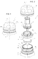
- the push-pull aseptic dispenser cap further comprises a tubular projection that protrudes cantilevered from said second flat upper wall, in the opposite direction to the neck, so as to extend completely outside and above said neck, and a cylinder shaped dispenser cap, provided at the top with a central hole through which the beverage can flow out and provided at the bottom with a cylindrical stop element.
- the dispenser cap is slidingly coupled to the tubular projection so that it can be moved axially between a lowered closed position, in which the cylindrical stop element is fitted in a fluid-tight manner in a central hole obtained in the second flat wall in order to seal the bottle hermetically, and a raised delivery position, in which the cylindrical stop element is at a distance from the second flat wall so as to disengage the through hole and place the space inside the bottle in communication with the central through hole in the dispenser cap, via a central channel in the projection, and thus to allow the beverage to be removed from the bottle.
- the push-pull aseptic dispenser cap further comprises an external capsule shaped so as to be coupled to the main cylindrical body and thus internally contain the dispenser cap to protect it.
- the push-pull aseptic dispenser caps of the type described above are widely used in the beverage bottle market in that they have made it possible to eliminate the paper-aluminium disk that was used in previous caps as a membrane to close the neck in order to guarantee the maintenance of the hermetic seal of the bottle prior to its use.
- the cap described above has an improved structure capable of both simplifying the processes of manufacturing the cap and of coupling it to the bottle, with a subsequent reduction in production costs, and of making the part handier for beverage consumers to use.
- the need is felt to reduce the risk of contamination of the beverage via the cap, before and during the use of the bottle.
- the cap described above has some structural mechanical problems that seriously affect the bottle's capacity to withstand top loading, and therefore represent limits in terms of the volume of the bottle packaging.
- the weight of the other bottles stacked on top of a bottle is discharged, through the capsule, directly onto the dispenser cap and onto the tubular projection outside the neck and may in certain conditions, for example when a maximum weight limit is exceeded, cause plastic deformation/warping of the dispenser cap and of the tubular projection, and deterioration of the closing mechanism defined by the closing element and the hole.
- said closing element causes flaring of the hole, damaging the hermetic seal of the cap in the closed position and thus exposing the beverage to the risk of contamination.
- this problem is overcome by limiting the number of layers of bottles that are stacked in the packaging to below a maximum limit and by subjecting the cap to two sterilization processes before it is coupled to the bottle, that is, ionizing radiation and immersion of the cap in a sanitizing liquid.
- the cap is also particularly prone to being a vehicle of contamination of the beverage during the use of the bottle by the user.
- the dispenser cap repeatedly comes into contact with the hands of the user who, in practice, tends to take hold of it in order to more easily overcome the non-negligible resistance thereof to slide on the projection.
- a second need is to reduce the risk of suffocation of users due to accidentally swallowing parts of the cap.
- the cap described above can easily be detached from the bottle.
- a simple manual operation is all that is required to unscrew the main body from the neck.
- the user is able to refill the bottle several times.
- the bottle is designed and produced to be used just once, using it for too long and repeatedly fitting/removing the cap results in a weakening/wearing out of the parts of said cap, in particular of the dispenser cap, which will in time gradually tend to become detached from the projection and thus give rise to said risk of swallowing.
- US2015266634 A1 describes tubular fastening means fixed to the neck of the bottle and a cap member coupled to the tubular fastening means to close the bottle.
- the tubular fastening means are suitable to contain an article and comprise a tubular body with slots in the side, while the cap member is provided with an inner tubular portion that slides inside the tubular means between a closed position of the slots and an open position thereof so that the article contained in the tubular means is poured into the bottle.
- the cap described in US 2015 266 634 merely has the function of closing the bottle and is not suitable to be easily gripped between the lips/teeth of the user to allow the latter to drink the beverage contained in the bottle.
- the cap member has the structural mechanical problems described above in that the weight of bottles stacked on top of it would tend to deform the upper annular portion 114 which protrudes above the neck of the bottle even in its closed condition.
- US2009057262 A1 describes a conventional bottle cap including an additive holding unit which is supported in the mouth of the bottle by an upper flange and contains an additive, and a tubular unit mounted so as to slide in the additive holding unit from and towards an extracted position in which it opens openings in the side of the additive holding unit to discharge the additive into the bottle, and is closed at the top by a seal.
- the cap described in US2009057262 is not suitable for use as a push-pull aseptic cap because once the upper seal has been opened the beverage is exposed to contamination.
- FR1375655 A describes a conventional dispenser spout that can be fitted by a user to the neck of the bottle and which is manually axially moved by the user to control the amount of beverage to be discharged.
- the dispenser spout described in FR1375655 is not suitable for use as a push-pull aseptic cap because the beverage is highly susceptible to contamination both before and during the use of the bottle.
- US20070199914 and DE29708202 U1 also describe conventional push-pull caps in which the tubular projection always protrudes from the top of the neck and is therefore prone to the structural mechanical problems described above.
- the purpose of the present invention is thus to provide a solution that achieves at least the aims listed above.
- a fully “retractable” push-pull aseptic dispenser cap for bottles 2 designed to hold beverages, preferably, but not necessarily, so-called “pressurized” beverages.
- the bottles 2 may contain water, orangeade, or any similar kind of beverage.
- the pressure inside the bottle 2 may be, for example, approximately 1 Bar.
- the cap 1 implemented according to the present invention may also be used to close bottles 2 containing beverages that are not "pressurized", for example such as tea, fruit juice, or any other similar kind of beverage.
- the bottle 2 to which the cap 1 is coupled may be of the single-use, or disposable type, it is made of plastic material, for instance polyethylene terephthalate (PET) or a similar material, and essentially comprises a cylindrical neck or mouth 3 preferably having a smooth inner wall 3a and, preferably, an outer wall 3b that is at least partially threaded.
- PET polyethylene terephthalate
- the cap 1 comprises a guide-body 4 having a reference axis A (vertical in the example that is illustrated) and is designed to be permanently coupled, i.e., in a manually unmovable manner, to the mouth 3 of the bottle 2.
- the guide-body 4 may be made of plastic material, such as for example polyethylene, preferably, but not necessarily, HDPE (High-Density Polyethylene) and is provided with a tubular shaped inner chamber 4a which extends inside the mouth 3 and is closed at the bottom.
- polyethylene preferably, but not necessarily, HDPE (High-Density Polyethylene)
- HDPE High-Density Polyethylene
- the cap 1 further comprises a straw or shutter-nipple 5, which is made of plastic material and is coupled in a telescopic manner in the guide-body 4 so as to axially move the guide-body 4 inside the inner chamber 4a along the axis A.
- a straw or shutter-nipple 5 which is made of plastic material and is coupled in a telescopic manner in the guide-body 4 so as to axially move the guide-body 4 inside the inner chamber 4a along the axis A.
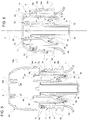
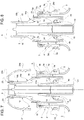
- the shutter-nipple 5 can move axially inside the inner chamber 4a, between a retracted position (shown in Figures 5 and 6 ), in which the shutter-nipple 5 closes the through openings 4b to close the mouth 3 hermetically, and an extracted position (shown in Figures 3, 4 , 7 and 8 ), in which the shutter-nipple 5 is arranged so that, on the one hand, it disengages the through openings 4b and thus allows the beverage to flow through them into the inner chamber 4a, and, on the other, it protrudes cantilevered from the guide-body 4 so that it can easily be gripped between the user's lips/teeth.
- the shutter-nipple 5 in the retracted position, is arranged inside the inner chamber 4a of the guide-body 4 so that, on the one hand, the shutter-nipple 5 engages the through openings 4b so as to close them in a fluid-tight manner, and, on the other, it has its upper distal end completely inside the inner chamber 4a.
- the shutter-nipple 5 in the retracted position, conveniently assumes a so-called "retracted" position, in which said shutter-nipple 5 is contained/arranged completely inside the guide-body 4.
- the shutter-nipple 5 in the extracted position, is arranged so that, on the one hand, it opens the through openings 4b to place the body of the bottle 2 containing the beverage in hydraulic communication with the shutter-nipple 5 via the inner chamber 4a, and, on the other, it extends cantilevered outwardly from the upper end of the guide-body 4 (top in Figures 4 , 7 and 8 ) so as to allow the user to sip/suck the beverage through said shutter-nipple 5.
- the guide-body 4 comprises a cup-shaped body 6 that is fitted inside the mouth 3 of the bottle 2.
- the cup-shaped body 6 is provided with a cylindrical wall 7 that is fitted inside the mouth 3, is open at the top, and is closed at the bottom by a bottom wall 8.
- the outer surface of the cylindrical wall 7 is substantially smooth (not threaded) and is shaped so as to be arranged facing the smooth inner surface 3a (not threaded) of the mouth 3.
- the cylindrical wall 7 extends coaxially to the axis A downwards starting from the top edge of the mouth 3 so as to lie/extend completely inside the mouth 3, whereas the inner surface of said cylindrical wall 7 forms/delimits the inner chamber 4a of the guide-body 4.
- the upper edge of the cylindrical wall 7 comprises an annular flange 9 structured so as to fasten the guide-body 4 to the bottle 2 in a manually fixed manner.
- the annular flange 9 preferably has a substantially L-shaped profile.
- the annular flange 9 comprises a flat annular portion 9a, orthogonal to the axis A, which extends cantilevered outwards from the upper edge of the cylindrical wall 7 and has a portion of its bottom surface that abuts against the top annular edge of the mouth 3.
- the annular flange 9 further comprises a cylindrical annular portion 9b coaxial to the axis A, which extends downwards from the outer edge of the flat annular portion 9a and has its inner surface that abuts against/rests upon the outer surface of the mouth 3 preferably in correspondence with the top annular edge thereof.
- the annular flange 9 further comprises an inner annular tongue 9c which extends downwards from an intermediate position of the flat annular portion 9a, between the outer surface of the cylindrical wall 7 and the cylindrical portion 9b, so as to abut against the inner surface of the mouth 3.
- annular seat 10 coaxial to the axis A, inside which, in use, a protruding projection or annular rib 11 of the mouth 3 is arranged.
- annular rib 11 protrudes outwards from a smooth circular sector of the outer surface of the mouth 3 arranged above the threaded portion, preferably in correspondence with the top edge of said mouth 3.
- the annular rib 11 may preferably be shaped to have a cross section (vertical) substantially complementary to the cross section (vertical) of the respective annular seat 10 so as to achieve with the latter, cooperating with the inner annular tongue 9c, a snap coupling (undercut coupling) of the guide-body 4 in the mouth 3.
- the annular rib 11 when snapped into the seat 10, holds the guide-body 4 permanently anchored to the mouth 3 and thus achieves a manually unmovable coupling of the cap 1 to the bottle 2.
- the inner annular tongue 9c is structured to bend slightly inwards when fitted on the mouth 3 so as to press elastically on the inner surface of the mouth 3 and achieve a fluid-tight coupling on the latter.
- the guide-body 4 of the cap 1 cannot be detached from the bottle 2 by means of a simple manual operation, this conveniently prevents the bottle from being re-used and refilled when all the contents have been consumed.
- the bottom wall 8 of the cup-shaped body 6 is substantially cap or bell shaped with the concavity/roundedness protruding towards the inside of said cup-shaped body 6.
- the bottom wall 8 comprises a central hub 12 closed at the bottom which extends inside the cup-shaped body 6 remaining coaxial to the axis A.
- the hub 12 may comprise an upper portion 12a which extends inside the inner chamber 4a towards the annular flange 9, and a lower portion 12b that extends preferably below the lower annular edge of the cup-shaped body 6 so as to partially protrude inside the body of the bottle 2.
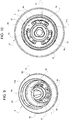
- the through openings 4b consist of through holes, which are preferably obtained in the rounded portion of the bottom wall 8 surrounding the hub 12.
- the through openings 4b may be distributed on the top of the roundedness of the bottom wall 8 that surrounds the hub 12 so as to form one or more perforated sectors 13 through which the beverage passes/flows towards the inner chamber 4a.
- each perforated sector 13 comprises a plurality of through holes, preferably three or more.
- the Applicant has found that providing at least three perforated sectors 13 each with at least three through holes with a diameter of approximately 1 mm, achieves, on the one hand, the advantage of regulating the amount of beverage that can be discharged from the bottle through the holes and, on the other, of preventing the beverage from flowing through the holes when the bottle is tipped over.
- the through openings 4b are made inside a series of concavities or recesses 14 formed in the rounded portion of the bottom wall 8 surrounding the hub 12.
- the recesses 14 are open towards the inner chamber 4a, whereas the through openings 4b are preferably made in the bottom walls of the recesses 14 on which they form said perforated sectors 13.
- the lower surface of the bottom wall 8 may also be provided with collars 15, each of which extends along the perimeter of a bottom wall of the respective recess 14 so as to surround the through openings 4b that are present in said recess 14.
- Each collar 15 conveniently forms a dispensing duct suitable to carry the beverage at a predefined flow rate towards the through openings 4b.
- the shutter-nipple 5 As far as the shutter-nipple 5 is concerned, it comprises a tubular body 16 coaxial to the axis A which is coupled in a telescopic manner to the cup-shaped body 6 so that it has a lower annular edge fitted so as to slide on the inner surface of the inner chamber 4a, and comprises a central stem 18 which extends coaxially to the reference axis A and is, in turn, fitted in an axially sliding manner in the hub 12 so as to maintain the tubular body 16 in a substantially central position coaxial to the axis A, during the axial movement of the shutter-nipple 5.
- the tubular body 16 is separate and distinct from the guide-body 4, i.e. it is completely independent and detachable from the guide-body 4 and may preferably be made of polypropylene.
- the Applicant has found that when the tubular body 16 is made of polypropylene and the guide-body 4 of polyethylene, the lower annular edge of the tubular body 6 adheres well to the inner sliding surface of the inner chamber 4a.
- the inner chamber 4a which is less rigid than the tubular body 6, tends to become locally deformed when it comes into contact with the latter and its surface thus adapts to the rigid outside shape of the lower annular edge.
- the tubular body 16 has a flared or truncated cone shaped lower tubular portion 16a having the greatest perimeter edge facing the bottom wall 8, and an upper tubular portion 16b, preferably cylindrical, which extends starting from the smaller upper perimeter edge of the lower tubular portion 16a towards the flange 9 and constitutes the end portion of the shutter-nipple 5 used by the user to drink the beverage.
- the tubular body 16 is also provided with a series of internal closing segments or fins 20 which extend from the inner surface of said tubular body 16 towards the bottom wall 8, and are designed, in use, to abut against the bottom wall 8 so as to close, in a fluid-tight manner, the through openings 4b when the shutter-nipple 5 is in the retracted position.
- the closing fins 20 are angularly distributed on the inner surface of the tubular body 16, preferably angularly equally spaced, so as to be aligned with the underlying recesses 14 along respective axes parallel to the axis A.
- the closing fins 20 also have free lower ends shaped so as to engage the recesses 14 in order to close the through openings 4b provided therein when the shutter-nipple 5 is in the retracted position and, vice versa, to disengage the recesses 14 to open the through openings 4b when the shutter-nipple 5 is not in the retracted position ( Figures 5-6 ) .
- the closing fins 20 are fixed to the inner surface of the lower tubular portion 16a of the tubular body 16, preferably approximately on the smaller upper annular edge of said lower tubular portion 16a and are arranged in planes substantially parallel to the axis A (vertical in the Figures), whereas the free lower ends of the closing fins 20 may preferably, but not necessarily, have an arched shape complementary to a corresponding arched shape of the respective recesses 14.
- the lower tubular portion 16a may have an inner surface with a shape that is substantially complementary to the bottom wall 8 so as to be able to completely rest on the latter and at the same time fit its greater lower annular edge inside an annular groove 8a provided in the bottom wall 8 ( Figures 5, 6 , 7 and 8 ).
- the lower portion of the bottom wall 8 may be substantially cylinder shaped, arranged adjacent to the lower portion of the cylindrical wall 7 so as to delimit therewith the annular groove 8a.
- the annular groove 8a may be dimensioned so that, in use, it holds the greater lower annular edge of the lower tubular portion 16a so that the movement of the nipple 5 from the retracted position requires the application of a minimum predefined force by the user ( Figure 5 and 6 ).
- the stem 18 of the nipple 5 and the hub 12 are coupled so as to be able to slide axially one with respect to the other.
- the stem 18 of the nipple 5 and the hub 12 are also structured so as to be angularly fixed with respect to one another so that the nipple 5, in use, cannot rotate about the axis A with respect to the guide-body 4.
- the cross sections of the stem 18 and of the central inner tubular wall of the hub 12 which receives the stem 18 may be shaped to complement one another, so that the angular coupling between them determines the correct alignment of the closing fins 20 with the respective recesses 14.
- the cross section of the stem 18 and the central duct of the hub 12 may be star shaped, toothed, triangular or of a similar shape.
- the cap 1 may also be provided with a first mechanical end-of-stroke designed to stop the movement of the shutter-nipple 5 when the shutter-nipple 5 reaches the extracted position.
- the mechanical end-of-stroke may comprise a cylindrical collar 21 coaxial to the axis A, which extends cantilevered upwards from the flat annular portion 9a of the flange 9 and delimits with its inner surface the upper end portion of the chamber 4a.
- the mechanical end-of-stroke may further comprise an annular projection 22, which protrudes inwards from the inner surface of the collar 21, and an annular groove 23 which is obtained in the outer surface of the lower tubular portion 16a in correspondence with the respective lower edge and is designed, in use, to be engaged by the annular projection 22 so as to stop the axial movement of the shutter-nipple 5 and thus prevent it from being uncoupled from the cup-shaped body 6.
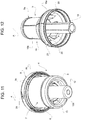
- the cap 1 further comprises a cover or capsule 24 that may be made of plastic material, such as for example polyethylene, preferably HDPE, and is designed to be coupled to the mouth 3 to protect the guide-body 4 and the shutter-nipple 5.
- a cover or capsule 24 may be made of plastic material, such as for example polyethylene, preferably HDPE, and is designed to be coupled to the mouth 3 to protect the guide-body 4 and the shutter-nipple 5.
- the capsule 24 is shaped so as to have a substantially cylindrical side wall 24a coaxial to the axis A, which has a threaded inner surface designed in use to be screwed onto the threaded outer surface of the mouth 3; and a flat wall 24b, which lies in a plane substantially orthogonal to the axis A, closes the upper end of the side wall 24a, and is designed in use to be arranged so that its inner surface abuts against the upper edge of the collar 21 when the capsule 24 is screwed completely onto the thread of the mouth 3 ( Figure 6 ).
- the cap 1 further comprises a coupling member 25 designed to couple the capsule 24 in a stable but easily removable manner to the shutter-nipple 5 so that an axial movement of the capsule 24 along the axis A with respect to the mouth 3 results in a corresponding axial movement of the shutter-nipple 5 with respect to the guide-body 4.
- the coupling member 25 may further comprise on the inner surface an annular projection 26 coaxial to the axis A on which there is formed a central annular groove 27, designed to house the upper annular edge of the shutter-nipple 5.
- the upper annular edge of the shutter-nipple 5 engages by interference in the annular groove 27 and remains trapped/held between the two inner walls of the annular projection 26 that delimit the annular groove 27 ( Figures 6 and 7 ).
- the upper annular edge of the shutter-nipple 5 is provided with an annular projection 5a that protrudes outwards and is arranged inside the annular groove 27 so that it is centrally anchored to the capsule 24 which is designed to axially slide the nipple 5.
- the upper annular edge of the shutter-nipple 5 which is angularly fixed with respect to the guide-body 3, slides idly inside the groove 27 of the capsule 24 while remaining anchored thereto during the axial movement of the capsule 24.
- the capsule 24 further comprises three teeth 28 (only one of which is illustrated in Figure 14 ) preferably helical shaped or rectilinear and sloping with respect to a plane orthogonal to the axis A, which are arranged angularly equally spaced from one another along the upper perimeter edge of the inner surface of the side wall 24a, and are designed in use to engage corresponding grooves 29 having a complementary shape obtained in the outer surface of the cylindrical annular wall 9b of the flange 9 ( Figure 11 ).
- the capsule 24 further comprises a breakable tamper-proof ring 24c that forms the lower part of the side wall 24a, which is preferably undercut-coupled to a ring or flat annular portion 3d arranged on the outer surface of the mouth 3 immediately below the threaded portion thereof.
- the breakable tamper-proof ring 24c is designed to break and come away from the remaining portion of the side wall 24a of the capsule 24 the first time the capsule 24 is raised axially from the annular portion 28 of the mouth 3 the first time said capsule 24 is unscrewed ( Figure 5 ).
- the cap 1 is pre-assembled by arranging the shutter-nipple 5 in the guide-body 4.
- the stem 18 is inserted in the hub and at the same time the tubular body 16 is coupled in a telescopic manner in the inner chamber 4a of the guide-body 4.
- the shutter-nipple 5 is then moved axially to the retracted position.
- the capsule 24 is coupled axially in the guide-body 4 and is partially rotated about the axis A to fit/screw the three teeth 28 of the capsule in the grooves 29 of the guide-body 4.
- the presence of the teeth 28 in the capsule 24 thus makes it possible to guarantee the angular coupling of the capsule 24 to the guide-body 4 and so prevent the accidental separation of the capsule 24 from said guide-body 4 during the assembly of the cap 1 on the bottle 2.
- the upper annular edge of the nipple 5 is coupled in the annular groove 27 of the capsule 24 and during the axial movement of the latter, its flat wall 24b makes the shutter-nipple 5 perform a brief axial movement along the axis A towards the bottom wall 8 to ensure that the nipple 5 reaches its retracted position in which the closing fins 20 engage in the recesses 14 closing the through openings 4b in a fluid-tight manner. It is worth pointing out that thanks to the hermetic closing of the through openings 4b achieved by the shutter-nipple 5, the tubular chamber 4a of the guide-body 4 is completely isolated from the outside.
- the assembly of the pre-assembled cap 1 on the bottle 2 comprises the steps of: placing the annular flange 9 so that it rests on the upper perimeter edge of the mouth 3, screwing the capsule 24 onto the threaded portion of the mouth 3 to axially push/pull the guide-body 4 downwards to a closed/protection position, in which the annular rib 11 engages in the annular seat 10 so as to achieve a snap coupling between the guide-body 4 and the mouth 3, and in which the breakable tamper-proof ring 24c is arranged below the annular portion 3d of the mouth 3.
- the beverage In the extracted position of the nipple 5, the beverage can be discharged from the bottle 2 to flow into the inner chamber 4a, through the through openings 4b, and can thus be delivered to the user through the tubular body 16 ( Figure 8 ).
- the cap described above achieves the following advantages.
- the cap is particularly robust and allows the bottle to withstand a greater top load.
- the nipple of the present cap in the retracted position, is arranged completely inside the chamber and so has no support function and is not subject to deformation/warping.
- the weight of any bottles stacked vertically on the capsule of the bottle underneath is fully discharged, through the flange of the cup-shaped body onto the top edge of the mouth of the bottle.
- any downward forces applied by the bottles stacked on top of the bottle push the closing fins further into the respective recesses which increases the hermetic seal without causing any flaring of the holes or contamination of the beverage.
- the coupling of the closing fins in the recesses and the coupling of the capsule create an inner tubular chamber which is isolated from the outside environment. Thanks to this, the process of sterilizing the cap by means of radiation can be eliminated, with all the consequences in terms of cost reduction.
- the arrangement of the nipple (retractable) inside the guide-body eliminates any risk of said nipple breaking when (for example after a fall) the upper portion of the bottle accidentally bangs against a rigid surface.
- the manually irremovable coupling achieved by the snap coupling of the flange to the mouth ensures that the bottle is only used once so that there is a lower possibility of the components accidentally coming off and the risk of swallowing such parts is greatly reduced.
- the push-pull cap described above does not affect the height of the bottle.
- the height of the push-pull cap described above, in the retracted position is substantially zero and thus entirely similar to conventional caps not of the push-pull type.
- the bottles provided with the cap described above can be stored in automatic dispensing machines for bottles with conventional caps, without requiring any changes to the storage and dispensing mechanisms of such machines.
Landscapes
- Engineering & Computer Science (AREA)
- Mechanical Engineering (AREA)
- Ceramic Engineering (AREA)
- Closures For Containers (AREA)
- Sealing Of Jars (AREA)
- Filling Of Jars Or Cans And Processes For Cleaning And Sealing Jars (AREA)
Claims (15)
- Aseptische Push-Pull-Spenderkappe (1) des einziehbaren Typs, umfassend:- einen Führungskörper (4), der eine Referenzachse (A) aufweist und dazu ausgelegt ist, mit der Mündung (3) einer Flasche (2) gekoppelt zu sein; wobei der Führungskörper (4) mit einer rohrförmigen Innenkammer (4a), einer zentralen Nabe (12), die sich koaxial zu der Referenzachse (A) innerhalb der rohrförmigen Kammer (4a) erstreckt, und Durchgangsöffnungen (4b) versehen ist, die in einem Abschnitt der Bodenwand (8) des Führungskörpers (4) ausgebildet sind, der bzw. die die Nabe (12) umgibt, und dazu ausgelegt sind, den Innenraum der Flasche (2), die das Getränk enthält, in Verbindung mit der Innenkammer (4a) zu bringen;- einen Verschlussnippel (5), der auf axial verschiebbare Weise mit dem Führungskörper (4) gekoppelt ist, um axial innerhalb der Innenkammer (4a) entlang der Referenzachse (A) zwischen einer zurückgezogenen Position, in der der Verschlussnippel (5) die Durchgangsöffnungen (4b) fluiddicht verschließt und sein oberes Ende vollständig in der Innenkammer (4a) aufweist, und einer herausgezogenen Position zu gleiten, in der der Verschlussnippel (5) auskragend bzw. freitragend von dem Führungskörper (4) nach außen vorsteht, so dass er leicht zwischen den Lippen/Zähnen des Benutzers ergriffen werden kann und die Durchgangsöffnungen (4b) außer Eingriff bringt, um von den letzteren das Getränk durch die Innenkammer (4a) aufnehmen zu können; wobei der Verschlussnippel (5) einen rohrförmigen Körper (16) umfasst, der von dem Führungskörper (4) getrennt und verschieden ist; wobei der rohrförmige Körper (16) in der Innenkammer (4a) auf teleskopartige Weise gekoppelt ist, dadurch gekennzeichnet, dass der Führungskörper (4) dazu ausgelegt ist, mit der Mündung (3) der Flasche auf manuell unbewegliche Weise gekoppelt zu sein, und dass der rohrförmige Körper (16) intern bzw. im Inneren einen zentralen Schaft (18) enthält, der sich koaxial zu der Referenzachse (A) erstreckt; der wobei der zentrale Schaft (18) auf axiale gleitende Weise in die Nabe (12) eingepasst ist und mit dem rohrförmigen Körper (16) zusammenwirkt, so dass sich der Verschlussnippel (5) zwischen der zurückgezogenen Position und der herausgezogenen Position verschiebbar ist.
- Kappe nach Anspruch 1, wobei der Schaft (18) und die Nabe (12) in Bezug zueinander winkelig fixiert bzw. befestigt sind, so dass sich der Nippel (5) in Gebrauch nicht um die Achse (A) relativ zu dem Führungskörper (4) drehen kann.
- Kappe nach Anspruch 1, wobei die Durchgangsöffnungen (4b) innerhalb einer Reihe von Aussparungen oder Vertiefungen (14) hergestellt sind, die in der Bodenwand (8) ausgebildet sind, die die Nabe (12) umgibt, wobei die Aussparungen oder Vertiefungen (14) zu der Innenkammer (4a) hin offen sind, wobei die Durchgangsöffnungen (4b) in den Bodenwänden der Aussparungen (14) ausgebildet sind, um in den letzteren perforierte Sektoren (13) zu bilden.
- Kappe nach Anspruch 1, wobei der Führungskörper (4) einen becherförmigen Körper (6) umfasst, der mit einer zylindrischen Wand (7) versehen ist, die in die Mündung (3) eingepasst ist, oben offen ist und ist unten durch die Bodenwand (8) verschlossen ist; wobei sich die zylindrische Wand (7) koaxial zu der Referenzachse (A) ausgehend von der Oberkante der Mündung (3) nach unten erstreckt, um sich vollständig innerhalb der Mündung (3) zu befinden/erstrecken; wobei die Innenfläche der zylindrischen Wand (7) die Innenkammer (4a) des Führungskörpers (4) bildet/begrenzt.
- Kappe nach Anspruch 1, wobei die Durchgangsöffnungen (4b) einen Durchmesser von ungefähr 1 mm aufweisen.
- Kappe nach Anspruch 1, wobei der röhrenförmige Körper (16) eine Reihe von Verschlusslamellen (20) umfasst, die dazu ausgelegt sind, die Durchgangsöffnungen (4b) fluiddicht zu verschließen, wenn der Verschlussnippel (5) in der zurückgezogenen Position ist.
- Kappe nach Anspruch 1, wobei der röhrenförmige Körper (16) eine Anzahl von Verschlusslamellen (20) umfasst, die winkelig an der Innenfläche des röhrenförmigen Körpers (16) verteilt sind, um mit den jeweiligen darunterliegenden Aussparungen (14) ausgerichtet zu sein, die in der Bodenwand (8) ausgebildet sind und in denen die Durchgangsöffnungen (4b) hergestellt sind; wobei die Verschlusslamellen (20) auch freie untere Enden aufweisen, die so geformt sind, dass sie in die Aussparungen (14) eingreifen, um die Durchgangsöffnungen (4b) darin zu verschließen, wenn sich der Verschlussnippel (5) in der zurückgezogenen Position befindet, und umgekehrt die Aussparungen (14) außer Eingriff zu bringen, um die Durchgangsöffnungen (4b) zu öffnen, wenn sich der Verschlussnippel (5) nicht in der zurückgezogenen Position befindet.
- Kappe nach den Ansprüchen 1 und 7, wobei die Querschnitte des Schafts (18) und der zentralen inneren rohrförmigen Wand der Nabe (12), die den Schaft (18) aufnimmt, so geformt sind, dass sie sich gegenseitig ergänzen, so dass die Winkelkopplung zwischen ihnen auch die korrekte Ausrichtung der Schließlamellen (20) mit den jeweiligen Aussparungen (14) bewirkt.
- Kappe nach Anspruch 1, wobei der röhrenförmige Körper (16) einen kegelstumpfförmigen unteren röhrenförmigen Abschnitt (16a), dessen größere Umfangskante der Bodenwand (8) zugewandt ist, und einen zylindrischen oberen röhrenförmigen Abschnitt (16b) aufweist, der sich ausgehend von der kleineren oberen Umfangskante des unteren rohrförmigen Abschnitts (16a) erstreckt und den Endabschnitt des Verschlussnippels (5) bildet, der von dem Benutzer zum Trinken des Getränks verwendet wird.
- Kappe nach Anspruch 1, die mit einem mechanischen Hubende versehen ist, das dazu ausgelegt ist, die Bewegung des Verschlussnippels (5) zu stoppen, wenn der Verschlussnippel (5) die herausgezogene Position erreicht.
- Kappe nach Anspruch 9 und 10, wobei das mechanische Hubende einen zylindrisch geformten Kragen (21) koaxial zu der Achse (A), der mit seiner Innenfläche den oberen Endabschnitt der Kammer (4a) begrenzt, einen ringförmigen Vorsprung (22), der von der Innenfläche des Kragens (21) nach innen vorsteht, und eine ringförmige Nut (23) umfasst, die in der Außenfläche des unteren rohrförmigen Abschnitts (16a) entsprechend der jeweiligen Unterkante ausgebildet ist und dazu ausgelegt ist, in Gebrauch durch den ringförmigen Vorsprung (22) in Eingriff genommen zu werden, um die axiale Bewegung des Verschlussnippels (5) zu stoppen.
- Kappe nach Anspruch 1, umfassend eine Schutzkapsel (24), die dazu ausgelegt ist, mit der Mündung (3) gekoppelt zu sein, um den Führungskörper (4) und den Verschlussnippel (5) im Inneren von sich zu enthalten; wobei die Kapsel (24) mit einem Kopplungsglied (25) versehen ist, das dazu ausgelegt ist, den Verschlussnippel (5) mit dem Körper der Kapsel (24) zu koppeln, so dass eine axiale Bewegung der Kapsel (24) die axiale Bewegung des Verschlussnippels (5) entlang der Referenzachse (A) bewirkt.
- Flasche für Getränke, umfassend die Kappe (1) nach einem der vorhergehenden Ansprüche.
- Betriebsverfahren für eine aseptische Push-Pull-Spenderkappe (1) des einziehbaren Typs, die umfasst:- einen Führungskörper (4), der eine Referenzachse (A) aufweist und dazu ausgelegt ist, mit der Mündung (3) einer Flasche (2) auf manuell unbewegliche Weise gekoppelt zu sein; wobei der Führungskörper (4) mit einer rohrförmigen Innenkammer (4a), einer zentralen Nabe (12), die sich koaxial zu der Referenzachse (A) innerhalb der rohrförmigen Kammer (4a) erstreckt, und Durchgangsöffnungen (4b) versehen ist, die in einem Abschnitt der Bodenwand (8) des Führungskörpers (4) ausgebildet sind, der bzw. die die Nabe (12) umgibt, und dazu ausgelegt sind, den Innenraum der Flasche (2), die das Getränk enthält, in Verbindung mit der Innenkammer (4a) zu bringen; und - einen Verschlussnippel (5), der einen rohrförmigen Körper (16) umfasst, der von dem Führungskörper (4) getrennt und verschieden ist, auf teleskopartige Weise in der Innenkammer (4a) gekoppelt ist und intern bzw. im Inneren einen zentralen Schaft (18) enthält, der sich koaxial zu der Referenzachse (A) erstreckt, um auf axiale gleitende Weise in die Nabe (12) eingepasst zu sein;wobei das Verfahren den Schritt des axialen Verschiebens des Verschlussnippels (5) innerhalb der Innenkammer (4a) entlang der Referenzachse (A) zwischen einer zurückgezogenen Position, in der der Verschlussnippel (5) die Durchgangsöffnungen (4b) fluiddicht verschließt und sein oberes Ende vollständig in der Innenkammer (4a) aufweist, und einer herausgezogenen Position umfasst, in der der Verschlussnippel (5) auskragend bzw. freitragend von dem Führungskörper (4) nach außen vorsteht, so dass er leicht zwischen den Lippen/Zähnen des Benutzers ergriffen werden kann und die Durchgangsöffnungen (4b) außer Eingriff bringt, um von den letzteren das Getränk durch die Innenkammer (4a) aufnehmen zu können.
- Verfahren nach Anspruch 14, wobei die Kappe eine Schutzkapsel (24) umfasst, die dazu ausgelegt ist, mit der Mündung (3) gekoppelt zu sein, um den Führungskörper (4) und den Verschlussnippel (5) im Inneren zu enthalten; wobei die Kapsel (24) mit einem Kopplungsglied (25) versehen ist, das dazu ausgelegt ist, den Verschlussnippel (5) mit dem Körper der Kapsel (24) zu koppeln,
wobei das Verfahren den Schritt des Bewegens der mit dem Verschlussnippel (5) gekoppelten Kapsel (24) entlang der Referenzachse (A) umfasst, um den Verschlussnippel (5) entlang der Referenzachse (A) zwischen der zurückgezogenen Position und der herausgezogenen Position zu bewegen.
Applications Claiming Priority (1)
| Application Number | Priority Date | Filing Date | Title |
|---|---|---|---|
| ITUB2015A005956A ITUB20155956A1 (it) | 2015-11-27 | 2015-11-27 | Tappo asettico dosatore push-pull per bottiglie |
Publications (2)
| Publication Number | Publication Date |
|---|---|
| EP3173350A1 EP3173350A1 (de) | 2017-05-31 |
| EP3173350B1 true EP3173350B1 (de) | 2019-10-02 |
Family
ID=55485185
Family Applications (1)
| Application Number | Title | Priority Date | Filing Date |
|---|---|---|---|
| EP16200825.4A Not-in-force EP3173350B1 (de) | 2015-11-27 | 2016-11-25 | Push-pull-spenderkappe |
Country Status (3)
| Country | Link |
|---|---|
| US (1) | US10196185B2 (de) |
| EP (1) | EP3173350B1 (de) |
| IT (1) | ITUB20155956A1 (de) |
Families Citing this family (16)
| Publication number | Priority date | Publication date | Assignee | Title |
|---|---|---|---|---|
| US10093460B2 (en) | 2015-08-14 | 2018-10-09 | Yeti Coolers, Llc | Container with magnetic cap |
| USD787893S1 (en) | 2015-11-20 | 2017-05-30 | Yeti Coolers, Llc | Jug |
| USD842030S1 (en) * | 2016-10-11 | 2019-03-05 | Runway Blue, Llc | Lid |
| US11034505B2 (en) | 2016-10-17 | 2021-06-15 | Yeti Coolers, Llc | Container and method of forming a container |
| EP3632274B1 (de) | 2016-10-17 | 2021-05-12 | Yeti Coolers, LLC | Behälter und verfahren zur herstellung eines behälters |
| US10959553B2 (en) | 2016-10-17 | 2021-03-30 | Yeti Coolers, Llc | Container and method of forming a container |
| PL236612B1 (pl) * | 2017-11-13 | 2021-02-08 | Krajewski Dariusz Jerzy | Nakrętka z dozownikiem do saszetek, zwłaszcza dla płynnych produktów spożywczych |
| US11053054B2 (en) | 2018-08-03 | 2021-07-06 | Gateway Plastics, Inc. | Spout fitment and cap |
| USD896572S1 (en) | 2018-08-20 | 2020-09-22 | Yeti Coolers, Llc | Container lid |
| USD883737S1 (en) | 2018-10-17 | 2020-05-12 | Yeti Coolers, Llc | Lid |
| USD897151S1 (en) | 2018-10-17 | 2020-09-29 | Yeti Coolers, Llc | Lid |
| USD883738S1 (en) | 2018-10-17 | 2020-05-12 | Yeti Coolers, Llc | Lid |
| JP7386727B2 (ja) * | 2020-02-28 | 2023-11-27 | 株式会社吉野工業所 | 塗布容器 |
| US11325762B2 (en) * | 2020-09-15 | 2022-05-10 | Elc Management Llc | Container-closure system |
| US12397975B2 (en) * | 2021-01-27 | 2025-08-26 | Gill, Llc | Multi-component sample container cap |
| CN114275338B (zh) * | 2021-11-24 | 2025-02-14 | 高金月 | 一种量化排油的自充气防漏通用油瓶盖 |
Family Cites Families (15)
| Publication number | Priority date | Publication date | Assignee | Title |
|---|---|---|---|---|
| US2936935A (en) * | 1957-05-02 | 1960-05-17 | Irving L Rabb | Dispensing head |
| FR1375655A (fr) * | 1959-09-04 | 1964-10-23 | Bouchon verseur escamotable à débit réglable | |
| US3521796A (en) * | 1968-06-10 | 1970-07-28 | Armstrong Cork Co | Sliding plunger dispensing closure |
| US3777936A (en) * | 1972-07-24 | 1973-12-11 | Polytop Corp | Safety dispensing closure |
| US4020981A (en) * | 1975-11-11 | 1977-05-03 | Anchor Hocking Corporation | Safety closure device |
| US4408700A (en) * | 1981-05-28 | 1983-10-11 | Owens-Illinois, Inc. | Multi-part dispensing closure having a frangible connecting web |
| US5145094A (en) * | 1990-08-20 | 1992-09-08 | Edward M. Bennett | Dispensing closure for squeeze bottle |
| DE29708202U1 (de) * | 1997-05-06 | 1997-07-03 | Chen, Yow-Chia, Shi Hu Chen, Changhua | Düse für Wasserflasche |
| IT1306677B1 (it) | 1999-06-29 | 2001-10-02 | San Benedetto Acqua Minerale | Tappo asettico per contenitori di liquidi. |
| FR2894566B1 (fr) * | 2005-12-13 | 2010-06-18 | Cep Ind | Conditionnement a systeme de distribution perfectionne |
| US20070199914A1 (en) * | 2006-02-24 | 2007-08-30 | Ming-Hua Hung | Cap assembly for bottles |
| KR20090014699A (ko) * | 2007-08-07 | 2009-02-11 | 조영국 | 첨가물 첨가 가능한 용기마개 |
| US20090230075A1 (en) * | 2008-03-11 | 2009-09-17 | Springer Kenny J | Easy pour low profile flow control dispensing cap |
| FR2953814A1 (fr) * | 2009-12-15 | 2011-06-17 | Fl Participations | Recipient equipe d'un bouchon d'ouverture et de refermeture etanche |
| US20150266634A1 (en) * | 2014-03-19 | 2015-09-24 | Fang-Lin YANG | Bottle cap and container with bottle cap |
-
2015
- 2015-11-27 IT ITUB2015A005956A patent/ITUB20155956A1/it unknown
-
2016
- 2016-11-25 EP EP16200825.4A patent/EP3173350B1/de not_active Not-in-force
- 2016-11-26 US US15/361,381 patent/US10196185B2/en not_active Expired - Fee Related
Non-Patent Citations (1)
| Title |
|---|
| None * |
Also Published As
| Publication number | Publication date |
|---|---|
| EP3173350A1 (de) | 2017-05-31 |
| US20170152080A1 (en) | 2017-06-01 |
| ITUB20155956A1 (it) | 2017-05-27 |
| US10196185B2 (en) | 2019-02-05 |
Similar Documents
| Publication | Publication Date | Title |
|---|---|---|
| EP3173350B1 (de) | Push-pull-spenderkappe | |
| CN103648923B (zh) | 具有用于将添加剂引入到容器的内含物中的机构的容器封闭装置 | |
| US7568576B2 (en) | Infusion cap | |
| PL200210B1 (pl) | Zamknięcie dozujące otwierane przez przekręcanie posiadające opcjonalną przekłuwaną wkładkę | |
| EP3551545B1 (de) | Verschluss mit ausgiesstülle und mittel zur einführung eines additivs in einen getränkebehälter | |
| EP1924509B1 (de) | Verschüttsicherer verschluss | |
| EP3921248B1 (de) | Verschluss für einen ausguss einer flexiblen dünnwandigen verpackung | |
| WO2009127039A1 (en) | Dispensing cap for beverage container | |
| US7967983B2 (en) | Liquid dispensing end-piece and liquid packaging and dispensing assembly comprising such an end-piece | |
| US9452868B2 (en) | Device for pouring liquid contained in a container | |
| US11884459B2 (en) | Spouted pouch and a closure assembly | |
| GB2559594A (en) | A liquid dispenser and method | |
| US7740134B2 (en) | Infusion cap with reservoir shiftable downwardly | |
| CN101573271A (zh) | 包装制品 | |
| JP3938960B2 (ja) | 複合キャップ | |
| US11452672B2 (en) | Pediatric dosing dispenser | |
| US20130032595A1 (en) | Drink containers with unremovable closures | |
| IT202300014775A1 (it) | Tappo erogatore per bottiglie | |
| WO2016020372A1 (en) | Improvements in or relating to push-pull closures | |
| HK1196805B (en) | Container closure having means for introducing an additive into the contents of the container | |
| NZ618717B2 (en) | Container closure having means for introducing an additive into the contents of the container |
Legal Events
| Date | Code | Title | Description |
|---|---|---|---|
| PUAI | Public reference made under article 153(3) epc to a published international application that has entered the european phase |
Free format text: ORIGINAL CODE: 0009012 |
|
| STAA | Information on the status of an ep patent application or granted ep patent |
Free format text: STATUS: THE APPLICATION HAS BEEN PUBLISHED |
|
| AK | Designated contracting states |
Kind code of ref document: A1 Designated state(s): AL AT BE BG CH CY CZ DE DK EE ES FI FR GB GR HR HU IE IS IT LI LT LU LV MC MK MT NL NO PL PT RO RS SE SI SK SM TR |
|
| AX | Request for extension of the european patent |
Extension state: BA ME |
|
| STAA | Information on the status of an ep patent application or granted ep patent |
Free format text: STATUS: REQUEST FOR EXAMINATION WAS MADE |
|
| 17P | Request for examination filed |
Effective date: 20171129 |
|
| RBV | Designated contracting states (corrected) |
Designated state(s): AL AT BE BG CH CY CZ DE DK EE ES FI FR GB GR HR HU IE IS IT LI LT LU LV MC MK MT NL NO PL PT RO RS SE SI SK SM TR |
|
| GRAP | Despatch of communication of intention to grant a patent |
Free format text: ORIGINAL CODE: EPIDOSNIGR1 |
|
| STAA | Information on the status of an ep patent application or granted ep patent |
Free format text: STATUS: GRANT OF PATENT IS INTENDED |
|
| INTG | Intention to grant announced |
Effective date: 20190114 |
|
| RIN1 | Information on inventor provided before grant (corrected) |
Inventor name: ZOPPAS, ENRICO |
|
| GRAS | Grant fee paid |
Free format text: ORIGINAL CODE: EPIDOSNIGR3 |
|
| GRAJ | Information related to disapproval of communication of intention to grant by the applicant or resumption of examination proceedings by the epo deleted |
Free format text: ORIGINAL CODE: EPIDOSDIGR1 |
|
| GRAL | Information related to payment of fee for publishing/printing deleted |
Free format text: ORIGINAL CODE: EPIDOSDIGR3 |
|
| STAA | Information on the status of an ep patent application or granted ep patent |
Free format text: STATUS: REQUEST FOR EXAMINATION WAS MADE |
|
| GRAP | Despatch of communication of intention to grant a patent |
Free format text: ORIGINAL CODE: EPIDOSNIGR1 |
|
| STAA | Information on the status of an ep patent application or granted ep patent |
Free format text: STATUS: GRANT OF PATENT IS INTENDED |
|
| INTC | Intention to grant announced (deleted) | ||
| INTG | Intention to grant announced |
Effective date: 20190613 |
|
| GRAA | (expected) grant |
Free format text: ORIGINAL CODE: 0009210 |
|
| STAA | Information on the status of an ep patent application or granted ep patent |
Free format text: STATUS: THE PATENT HAS BEEN GRANTED |
|
| AK | Designated contracting states |
Kind code of ref document: B1 Designated state(s): AL AT BE BG CH CY CZ DE DK EE ES FI FR GB GR HR HU IE IS IT LI LT LU LV MC MK MT NL NO PL PT RO RS SE SI SK SM TR |
|
| REG | Reference to a national code |
Ref country code: GB Ref legal event code: FG4D |
|
| REG | Reference to a national code |
Ref country code: CH Ref legal event code: EP Ref country code: AT Ref legal event code: REF Ref document number: 1185927 Country of ref document: AT Kind code of ref document: T Effective date: 20191015 |
|
| REG | Reference to a national code |
Ref country code: DE Ref legal event code: R096 Ref document number: 602016021591 Country of ref document: DE |
|
| REG | Reference to a national code |
Ref country code: IE Ref legal event code: FG4D |
|
| REG | Reference to a national code |
Ref country code: NL Ref legal event code: MP Effective date: 20191002 |
|
| REG | Reference to a national code |
Ref country code: LT Ref legal event code: MG4D |
|
| REG | Reference to a national code |
Ref country code: AT Ref legal event code: MK05 Ref document number: 1185927 Country of ref document: AT Kind code of ref document: T Effective date: 20191002 |
|
| PG25 | Lapsed in a contracting state [announced via postgrant information from national office to epo] |
Ref country code: PL Free format text: LAPSE BECAUSE OF FAILURE TO SUBMIT A TRANSLATION OF THE DESCRIPTION OR TO PAY THE FEE WITHIN THE PRESCRIBED TIME-LIMIT Effective date: 20191002 Ref country code: GR Free format text: LAPSE BECAUSE OF FAILURE TO SUBMIT A TRANSLATION OF THE DESCRIPTION OR TO PAY THE FEE WITHIN THE PRESCRIBED TIME-LIMIT Effective date: 20200103 Ref country code: NL Free format text: LAPSE BECAUSE OF FAILURE TO SUBMIT A TRANSLATION OF THE DESCRIPTION OR TO PAY THE FEE WITHIN THE PRESCRIBED TIME-LIMIT Effective date: 20191002 Ref country code: FI Free format text: LAPSE BECAUSE OF FAILURE TO SUBMIT A TRANSLATION OF THE DESCRIPTION OR TO PAY THE FEE WITHIN THE PRESCRIBED TIME-LIMIT Effective date: 20191002 Ref country code: BG Free format text: LAPSE BECAUSE OF FAILURE TO SUBMIT A TRANSLATION OF THE DESCRIPTION OR TO PAY THE FEE WITHIN THE PRESCRIBED TIME-LIMIT Effective date: 20200102 Ref country code: LT Free format text: LAPSE BECAUSE OF FAILURE TO SUBMIT A TRANSLATION OF THE DESCRIPTION OR TO PAY THE FEE WITHIN THE PRESCRIBED TIME-LIMIT Effective date: 20191002 Ref country code: AT Free format text: LAPSE BECAUSE OF FAILURE TO SUBMIT A TRANSLATION OF THE DESCRIPTION OR TO PAY THE FEE WITHIN THE PRESCRIBED TIME-LIMIT Effective date: 20191002 Ref country code: ES Free format text: LAPSE BECAUSE OF FAILURE TO SUBMIT A TRANSLATION OF THE DESCRIPTION OR TO PAY THE FEE WITHIN THE PRESCRIBED TIME-LIMIT Effective date: 20191002 Ref country code: PT Free format text: LAPSE BECAUSE OF FAILURE TO SUBMIT A TRANSLATION OF THE DESCRIPTION OR TO PAY THE FEE WITHIN THE PRESCRIBED TIME-LIMIT Effective date: 20200203 Ref country code: LV Free format text: LAPSE BECAUSE OF FAILURE TO SUBMIT A TRANSLATION OF THE DESCRIPTION OR TO PAY THE FEE WITHIN THE PRESCRIBED TIME-LIMIT Effective date: 20191002 Ref country code: SE Free format text: LAPSE BECAUSE OF FAILURE TO SUBMIT A TRANSLATION OF THE DESCRIPTION OR TO PAY THE FEE WITHIN THE PRESCRIBED TIME-LIMIT Effective date: 20191002 Ref country code: NO Free format text: LAPSE BECAUSE OF FAILURE TO SUBMIT A TRANSLATION OF THE DESCRIPTION OR TO PAY THE FEE WITHIN THE PRESCRIBED TIME-LIMIT Effective date: 20200102 |
|
| PG25 | Lapsed in a contracting state [announced via postgrant information from national office to epo] |
Ref country code: HR Free format text: LAPSE BECAUSE OF FAILURE TO SUBMIT A TRANSLATION OF THE DESCRIPTION OR TO PAY THE FEE WITHIN THE PRESCRIBED TIME-LIMIT Effective date: 20191002 Ref country code: RS Free format text: LAPSE BECAUSE OF FAILURE TO SUBMIT A TRANSLATION OF THE DESCRIPTION OR TO PAY THE FEE WITHIN THE PRESCRIBED TIME-LIMIT Effective date: 20191002 Ref country code: CZ Free format text: LAPSE BECAUSE OF FAILURE TO SUBMIT A TRANSLATION OF THE DESCRIPTION OR TO PAY THE FEE WITHIN THE PRESCRIBED TIME-LIMIT Effective date: 20191002 Ref country code: IS Free format text: LAPSE BECAUSE OF FAILURE TO SUBMIT A TRANSLATION OF THE DESCRIPTION OR TO PAY THE FEE WITHIN THE PRESCRIBED TIME-LIMIT Effective date: 20200224 |
|
| REG | Reference to a national code |
Ref country code: DE Ref legal event code: R119 Ref document number: 602016021591 Country of ref document: DE |
|
| PG25 | Lapsed in a contracting state [announced via postgrant information from national office to epo] |
Ref country code: AL Free format text: LAPSE BECAUSE OF FAILURE TO SUBMIT A TRANSLATION OF THE DESCRIPTION OR TO PAY THE FEE WITHIN THE PRESCRIBED TIME-LIMIT Effective date: 20191002 |
|
| REG | Reference to a national code |
Ref country code: CH Ref legal event code: PL |
|
| PG2D | Information on lapse in contracting state deleted |
Ref country code: IS |
|
| PG25 | Lapsed in a contracting state [announced via postgrant information from national office to epo] |
Ref country code: MC Free format text: LAPSE BECAUSE OF FAILURE TO SUBMIT A TRANSLATION OF THE DESCRIPTION OR TO PAY THE FEE WITHIN THE PRESCRIBED TIME-LIMIT Effective date: 20191002 Ref country code: RO Free format text: LAPSE BECAUSE OF FAILURE TO SUBMIT A TRANSLATION OF THE DESCRIPTION OR TO PAY THE FEE WITHIN THE PRESCRIBED TIME-LIMIT Effective date: 20191002 Ref country code: LI Free format text: LAPSE BECAUSE OF NON-PAYMENT OF DUE FEES Effective date: 20191130 Ref country code: EE Free format text: LAPSE BECAUSE OF FAILURE TO SUBMIT A TRANSLATION OF THE DESCRIPTION OR TO PAY THE FEE WITHIN THE PRESCRIBED TIME-LIMIT Effective date: 20191002 Ref country code: CH Free format text: LAPSE BECAUSE OF NON-PAYMENT OF DUE FEES Effective date: 20191130 Ref country code: LU Free format text: LAPSE BECAUSE OF NON-PAYMENT OF DUE FEES Effective date: 20191125 Ref country code: DK Free format text: LAPSE BECAUSE OF FAILURE TO SUBMIT A TRANSLATION OF THE DESCRIPTION OR TO PAY THE FEE WITHIN THE PRESCRIBED TIME-LIMIT Effective date: 20191002 Ref country code: IS Free format text: LAPSE BECAUSE OF FAILURE TO SUBMIT A TRANSLATION OF THE DESCRIPTION OR TO PAY THE FEE WITHIN THE PRESCRIBED TIME-LIMIT Effective date: 20200202 |
|
| PLBE | No opposition filed within time limit |
Free format text: ORIGINAL CODE: 0009261 |
|
| STAA | Information on the status of an ep patent application or granted ep patent |
Free format text: STATUS: NO OPPOSITION FILED WITHIN TIME LIMIT |
|
| REG | Reference to a national code |
Ref country code: BE Ref legal event code: MM Effective date: 20191130 |
|
| PG25 | Lapsed in a contracting state [announced via postgrant information from national office to epo] |
Ref country code: SK Free format text: LAPSE BECAUSE OF FAILURE TO SUBMIT A TRANSLATION OF THE DESCRIPTION OR TO PAY THE FEE WITHIN THE PRESCRIBED TIME-LIMIT Effective date: 20191002 Ref country code: IT Free format text: LAPSE BECAUSE OF FAILURE TO SUBMIT A TRANSLATION OF THE DESCRIPTION OR TO PAY THE FEE WITHIN THE PRESCRIBED TIME-LIMIT Effective date: 20191002 Ref country code: SM Free format text: LAPSE BECAUSE OF FAILURE TO SUBMIT A TRANSLATION OF THE DESCRIPTION OR TO PAY THE FEE WITHIN THE PRESCRIBED TIME-LIMIT Effective date: 20191002 |
|
| 26N | No opposition filed |
Effective date: 20200703 |
|
| PG25 | Lapsed in a contracting state [announced via postgrant information from national office to epo] |
Ref country code: DE Free format text: LAPSE BECAUSE OF NON-PAYMENT OF DUE FEES Effective date: 20200603 Ref country code: IE Free format text: LAPSE BECAUSE OF NON-PAYMENT OF DUE FEES Effective date: 20191125 |
|
| PG25 | Lapsed in a contracting state [announced via postgrant information from national office to epo] |
Ref country code: BE Free format text: LAPSE BECAUSE OF NON-PAYMENT OF DUE FEES Effective date: 20191130 Ref country code: SI Free format text: LAPSE BECAUSE OF FAILURE TO SUBMIT A TRANSLATION OF THE DESCRIPTION OR TO PAY THE FEE WITHIN THE PRESCRIBED TIME-LIMIT Effective date: 20191002 |
|
| PGFP | Annual fee paid to national office [announced via postgrant information from national office to epo] |
Ref country code: FR Payment date: 20201126 Year of fee payment: 5 |
|
| PG25 | Lapsed in a contracting state [announced via postgrant information from national office to epo] |
Ref country code: CY Free format text: LAPSE BECAUSE OF FAILURE TO SUBMIT A TRANSLATION OF THE DESCRIPTION OR TO PAY THE FEE WITHIN THE PRESCRIBED TIME-LIMIT Effective date: 20191002 |
|
| GBPC | Gb: european patent ceased through non-payment of renewal fee |
Effective date: 20201125 |
|
| PG25 | Lapsed in a contracting state [announced via postgrant information from national office to epo] |
Ref country code: HU Free format text: LAPSE BECAUSE OF FAILURE TO SUBMIT A TRANSLATION OF THE DESCRIPTION OR TO PAY THE FEE WITHIN THE PRESCRIBED TIME-LIMIT; INVALID AB INITIO Effective date: 20161125 Ref country code: MT Free format text: LAPSE BECAUSE OF FAILURE TO SUBMIT A TRANSLATION OF THE DESCRIPTION OR TO PAY THE FEE WITHIN THE PRESCRIBED TIME-LIMIT Effective date: 20191002 |
|
| PG25 | Lapsed in a contracting state [announced via postgrant information from national office to epo] |
Ref country code: GB Free format text: LAPSE BECAUSE OF NON-PAYMENT OF DUE FEES Effective date: 20201125 |
|
| PG25 | Lapsed in a contracting state [announced via postgrant information from national office to epo] |
Ref country code: TR Free format text: LAPSE BECAUSE OF FAILURE TO SUBMIT A TRANSLATION OF THE DESCRIPTION OR TO PAY THE FEE WITHIN THE PRESCRIBED TIME-LIMIT Effective date: 20191002 |
|
| PG25 | Lapsed in a contracting state [announced via postgrant information from national office to epo] |
Ref country code: MK Free format text: LAPSE BECAUSE OF FAILURE TO SUBMIT A TRANSLATION OF THE DESCRIPTION OR TO PAY THE FEE WITHIN THE PRESCRIBED TIME-LIMIT Effective date: 20191002 |
|
| PG25 | Lapsed in a contracting state [announced via postgrant information from national office to epo] |
Ref country code: FR Free format text: LAPSE BECAUSE OF NON-PAYMENT OF DUE FEES Effective date: 20211130 |