EP3172345B1 - Verfahren zum aufheizen von stahlblechen - Google Patents
Verfahren zum aufheizen von stahlblechen Download PDFInfo
- Publication number
- EP3172345B1 EP3172345B1 EP15749735.5A EP15749735A EP3172345B1 EP 3172345 B1 EP3172345 B1 EP 3172345B1 EP 15749735 A EP15749735 A EP 15749735A EP 3172345 B1 EP3172345 B1 EP 3172345B1
- Authority
- EP
- European Patent Office
- Prior art keywords
- zone
- heating
- temperature
- heated
- plate
- Prior art date
- Legal status (The legal status is an assumption and is not a legal conclusion. Google has not performed a legal analysis and makes no representation as to the accuracy of the status listed.)
- Active
Links
- 238000010438 heat treatment Methods 0.000 title claims description 129
- 238000000034 method Methods 0.000 title claims description 47
- 229910000831 Steel Inorganic materials 0.000 title claims description 41
- 239000010959 steel Substances 0.000 title claims description 41
- 229910052751 metal Inorganic materials 0.000 claims description 47
- 239000002184 metal Substances 0.000 claims description 47
- PALQHNLJJQMCIQ-UHFFFAOYSA-N boron;manganese Chemical compound [Mn]#B PALQHNLJJQMCIQ-UHFFFAOYSA-N 0.000 claims description 3
- 238000010791 quenching Methods 0.000 claims description 3
- 230000009466 transformation Effects 0.000 claims description 3
- 229910000617 Mangalloy Inorganic materials 0.000 claims description 2
- 229910001297 Zn alloy Inorganic materials 0.000 claims description 2
- 238000000265 homogenisation Methods 0.000 claims description 2
- 238000001816 cooling Methods 0.000 description 13
- 239000007789 gas Substances 0.000 description 13
- 230000008569 process Effects 0.000 description 11
- 230000001681 protective effect Effects 0.000 description 9
- 230000001939 inductive effect Effects 0.000 description 7
- 239000000463 material Substances 0.000 description 6
- 239000000203 mixture Substances 0.000 description 6
- 230000005855 radiation Effects 0.000 description 6
- 238000007669 thermal treatment Methods 0.000 description 5
- 230000015572 biosynthetic process Effects 0.000 description 4
- 230000001976 improved effect Effects 0.000 description 4
- 230000006698 induction Effects 0.000 description 4
- 239000010410 layer Substances 0.000 description 4
- HCHKCACWOHOZIP-UHFFFAOYSA-N Zinc Chemical compound [Zn] HCHKCACWOHOZIP-UHFFFAOYSA-N 0.000 description 3
- 239000000969 carrier Substances 0.000 description 3
- 239000000919 ceramic Substances 0.000 description 3
- 239000002131 composite material Substances 0.000 description 3
- 239000000835 fiber Substances 0.000 description 3
- 239000011265 semifinished product Substances 0.000 description 3
- 239000011701 zinc Substances 0.000 description 3
- 229910052725 zinc Inorganic materials 0.000 description 3
- 229910000789 Aluminium-silicon alloy Inorganic materials 0.000 description 2
- QVGXLLKOCUKJST-UHFFFAOYSA-N atomic oxygen Chemical compound [O] QVGXLLKOCUKJST-UHFFFAOYSA-N 0.000 description 2
- 238000000576 coating method Methods 0.000 description 2
- 238000002485 combustion reaction Methods 0.000 description 2
- 238000009792 diffusion process Methods 0.000 description 2
- 238000012432 intermediate storage Methods 0.000 description 2
- 238000004519 manufacturing process Methods 0.000 description 2
- 229910052760 oxygen Inorganic materials 0.000 description 2
- 239000001301 oxygen Substances 0.000 description 2
- 239000011241 protective layer Substances 0.000 description 2
- 239000004215 Carbon black (E152) Substances 0.000 description 1
- 229910001315 Tool steel Inorganic materials 0.000 description 1
- 238000010521 absorption reaction Methods 0.000 description 1
- 229910001566 austenite Inorganic materials 0.000 description 1
- 239000003054 catalyst Substances 0.000 description 1
- 238000004140 cleaning Methods 0.000 description 1
- 230000001276 controlling effect Effects 0.000 description 1
- 230000007797 corrosion Effects 0.000 description 1
- 238000005260 corrosion Methods 0.000 description 1
- 230000008878 coupling Effects 0.000 description 1
- 238000010168 coupling process Methods 0.000 description 1
- 238000005859 coupling reaction Methods 0.000 description 1
- 238000003618 dip coating Methods 0.000 description 1
- 230000000694 effects Effects 0.000 description 1
- 238000005485 electric heating Methods 0.000 description 1
- 230000002349 favourable effect Effects 0.000 description 1
- 239000000446 fuel Substances 0.000 description 1
- 229930195733 hydrocarbon Natural products 0.000 description 1
- 150000002430 hydrocarbons Chemical class 0.000 description 1
- 230000007257 malfunction Effects 0.000 description 1
- 229910000734 martensite Inorganic materials 0.000 description 1
- 238000002844 melting Methods 0.000 description 1
- 230000008018 melting Effects 0.000 description 1
- 229910000510 noble metal Inorganic materials 0.000 description 1
- 238000005457 optimization Methods 0.000 description 1
- 238000013021 overheating Methods 0.000 description 1
- 239000003973 paint Substances 0.000 description 1
- 238000005192 partition Methods 0.000 description 1
- 230000008092 positive effect Effects 0.000 description 1
- 230000009467 reduction Effects 0.000 description 1
- 230000001105 regulatory effect Effects 0.000 description 1
- 230000033764 rhythmic process Effects 0.000 description 1
- 238000007493 shaping process Methods 0.000 description 1
- 239000000758 substrate Substances 0.000 description 1
- 230000007704 transition Effects 0.000 description 1
- 238000003466 welding Methods 0.000 description 1
Images
Classifications
-
- C—CHEMISTRY; METALLURGY
- C21—METALLURGY OF IRON
- C21D—MODIFYING THE PHYSICAL STRUCTURE OF FERROUS METALS; GENERAL DEVICES FOR HEAT TREATMENT OF FERROUS OR NON-FERROUS METALS OR ALLOYS; MAKING METAL MALLEABLE, e.g. BY DECARBURISATION OR TEMPERING
- C21D9/00—Heat treatment, e.g. annealing, hardening, quenching or tempering, adapted for particular articles; Furnaces therefor
- C21D9/46—Heat treatment, e.g. annealing, hardening, quenching or tempering, adapted for particular articles; Furnaces therefor for sheet metals
-
- C—CHEMISTRY; METALLURGY
- C21—METALLURGY OF IRON
- C21D—MODIFYING THE PHYSICAL STRUCTURE OF FERROUS METALS; GENERAL DEVICES FOR HEAT TREATMENT OF FERROUS OR NON-FERROUS METALS OR ALLOYS; MAKING METAL MALLEABLE, e.g. BY DECARBURISATION OR TEMPERING
- C21D1/00—General methods or devices for heat treatment, e.g. annealing, hardening, quenching or tempering
- C21D1/34—Methods of heating
- C21D1/40—Direct resistance heating
-
- C—CHEMISTRY; METALLURGY
- C21—METALLURGY OF IRON
- C21D—MODIFYING THE PHYSICAL STRUCTURE OF FERROUS METALS; GENERAL DEVICES FOR HEAT TREATMENT OF FERROUS OR NON-FERROUS METALS OR ALLOYS; MAKING METAL MALLEABLE, e.g. BY DECARBURISATION OR TEMPERING
- C21D1/00—General methods or devices for heat treatment, e.g. annealing, hardening, quenching or tempering
- C21D1/34—Methods of heating
- C21D1/42—Induction heating
-
- C—CHEMISTRY; METALLURGY
- C21—METALLURGY OF IRON
- C21D—MODIFYING THE PHYSICAL STRUCTURE OF FERROUS METALS; GENERAL DEVICES FOR HEAT TREATMENT OF FERROUS OR NON-FERROUS METALS OR ALLOYS; MAKING METAL MALLEABLE, e.g. BY DECARBURISATION OR TEMPERING
- C21D1/00—General methods or devices for heat treatment, e.g. annealing, hardening, quenching or tempering
- C21D1/34—Methods of heating
- C21D1/52—Methods of heating with flames
-
- C—CHEMISTRY; METALLURGY
- C21—METALLURGY OF IRON
- C21D—MODIFYING THE PHYSICAL STRUCTURE OF FERROUS METALS; GENERAL DEVICES FOR HEAT TREATMENT OF FERROUS OR NON-FERROUS METALS OR ALLOYS; MAKING METAL MALLEABLE, e.g. BY DECARBURISATION OR TEMPERING
- C21D1/00—General methods or devices for heat treatment, e.g. annealing, hardening, quenching or tempering
- C21D1/62—Quenching devices
- C21D1/673—Quenching devices for die quenching
-
- F—MECHANICAL ENGINEERING; LIGHTING; HEATING; WEAPONS; BLASTING
- F27—FURNACES; KILNS; OVENS; RETORTS
- F27B—FURNACES, KILNS, OVENS, OR RETORTS IN GENERAL; OPEN SINTERING OR LIKE APPARATUS
- F27B9/00—Furnaces through which the charge is moved mechanically, e.g. of tunnel type; Similar furnaces in which the charge moves by gravity
- F27B9/06—Furnaces through which the charge is moved mechanically, e.g. of tunnel type; Similar furnaces in which the charge moves by gravity heated without contact between combustion gases and charge; electrically heated
- F27B9/062—Furnaces through which the charge is moved mechanically, e.g. of tunnel type; Similar furnaces in which the charge moves by gravity heated without contact between combustion gases and charge; electrically heated electrically heated
-
- F—MECHANICAL ENGINEERING; LIGHTING; HEATING; WEAPONS; BLASTING
- F27—FURNACES; KILNS; OVENS; RETORTS
- F27B—FURNACES, KILNS, OVENS, OR RETORTS IN GENERAL; OPEN SINTERING OR LIKE APPARATUS
- F27B9/00—Furnaces through which the charge is moved mechanically, e.g. of tunnel type; Similar furnaces in which the charge moves by gravity
- F27B9/06—Furnaces through which the charge is moved mechanically, e.g. of tunnel type; Similar furnaces in which the charge moves by gravity heated without contact between combustion gases and charge; electrically heated
- F27B9/068—Furnaces through which the charge is moved mechanically, e.g. of tunnel type; Similar furnaces in which the charge moves by gravity heated without contact between combustion gases and charge; electrically heated heated by radiant tubes, the tube being heated by a hot medium, e.g. hot gases
-
- F—MECHANICAL ENGINEERING; LIGHTING; HEATING; WEAPONS; BLASTING
- F27—FURNACES; KILNS; OVENS; RETORTS
- F27B—FURNACES, KILNS, OVENS, OR RETORTS IN GENERAL; OPEN SINTERING OR LIKE APPARATUS
- F27B9/00—Furnaces through which the charge is moved mechanically, e.g. of tunnel type; Similar furnaces in which the charge moves by gravity
- F27B9/30—Details, accessories, or equipment peculiar to furnaces of these types
- F27B9/36—Arrangements of heating devices
-
- C—CHEMISTRY; METALLURGY
- C21—METALLURGY OF IRON
- C21D—MODIFYING THE PHYSICAL STRUCTURE OF FERROUS METALS; GENERAL DEVICES FOR HEAT TREATMENT OF FERROUS OR NON-FERROUS METALS OR ALLOYS; MAKING METAL MALLEABLE, e.g. BY DECARBURISATION OR TEMPERING
- C21D2211/00—Microstructure comprising significant phases
- C21D2211/001—Austenite
-
- C—CHEMISTRY; METALLURGY
- C21—METALLURGY OF IRON
- C21D—MODIFYING THE PHYSICAL STRUCTURE OF FERROUS METALS; GENERAL DEVICES FOR HEAT TREATMENT OF FERROUS OR NON-FERROUS METALS OR ALLOYS; MAKING METAL MALLEABLE, e.g. BY DECARBURISATION OR TEMPERING
- C21D2221/00—Treating localised areas of an article
-
- F—MECHANICAL ENGINEERING; LIGHTING; HEATING; WEAPONS; BLASTING
- F27—FURNACES; KILNS; OVENS; RETORTS
- F27B—FURNACES, KILNS, OVENS, OR RETORTS IN GENERAL; OPEN SINTERING OR LIKE APPARATUS
- F27B9/00—Furnaces through which the charge is moved mechanically, e.g. of tunnel type; Similar furnaces in which the charge moves by gravity
- F27B9/12—Furnaces through which the charge is moved mechanically, e.g. of tunnel type; Similar furnaces in which the charge moves by gravity with special arrangements for preheating or cooling the charge
- F27B2009/124—Cooling
-
- Y—GENERAL TAGGING OF NEW TECHNOLOGICAL DEVELOPMENTS; GENERAL TAGGING OF CROSS-SECTIONAL TECHNOLOGIES SPANNING OVER SEVERAL SECTIONS OF THE IPC; TECHNICAL SUBJECTS COVERED BY FORMER USPC CROSS-REFERENCE ART COLLECTIONS [XRACs] AND DIGESTS
- Y02—TECHNOLOGIES OR APPLICATIONS FOR MITIGATION OR ADAPTATION AGAINST CLIMATE CHANGE
- Y02P—CLIMATE CHANGE MITIGATION TECHNOLOGIES IN THE PRODUCTION OR PROCESSING OF GOODS
- Y02P10/00—Technologies related to metal processing
- Y02P10/25—Process efficiency
Definitions
- the invention relates to a method for heating up steel sheets, in particular steel sheets, which are then subjected to a hot forming and hardening step.
- steel sheets that are to be subjected to a hot forming step and quench hardening must first be heated - at least in some areas - to an austenitizing temperature in order to enable the austenite to be converted into martensite and thus to produce a hardened structure.
- the structure must be heated above the so-called AC3 point of the steel material.
- a method for heating a molded component to different temperatures is to be designed in such a way that, despite a continuous passage through a heating device, the molded components undergo a heat treatment with improved temperature control that is necessary for the subsequent press hardening have.
- this document suggests that the molded component be heated differently during its conveyance through a heating element field with the aid of heating elements which are arranged in longitudinal and transverse rows with respect to the conveying direction and can be controlled at least in groups with different heating power, so that parts of the sheet metal reach an austenitizing temperature while other parts of the sheet do not reach this.
- heating elements with different heating power should be able to be controlled, with the possibility of controlling heating elements both along longitudinal rows and along transverse rows, at least in groups, independently of one another, and influencing the temperature of the molded components in a longitudinal strip running in the conveying direction during component conveyance in order not only to achieve but also to be able to maintain predetermined temperature levels in the area of such longitudinal strips.
- cooling devices that can be controlled along desired longitudinal rows can also cool the components in strips in the conveying direction.
- the device should have several heating stations, whereby a first heating station should be present with an inductive or inductively operated heating device in which the sheet metal workpieces can be quickly heated to a specified temperature without lingering, a second heating station in which the sheet metal workpieces stay and be heated or cooled to a predetermined temperature or kept at a certain temperature and a third heating station in which the sheet metal workpieces stay and can be heated, cooled or held to a predetermined temperature.
- a first heating station should be present with an inductive or inductively operated heating device in which the sheet metal workpieces can be quickly heated to a specified temperature without lingering
- a second heating station in which the sheet metal workpieces stay and be heated or cooled to a predetermined temperature or kept at a certain temperature
- a third heating station in which the sheet metal workpieces stay and can be heated, cooled or held to a predetermined temperature.
- the first heating station should enable rapid and targeted heating of the sheet metal workpieces due to the inductive heating principle, the first heating station preferably being designed as a through station and the sheet metal pieces to be heated being carried out individually or, if necessary, in several and without significant dwell time through the first station Heating can take place by longitudinal or transverse field induction.
- the second and third heating stations can be operated in different ways depending on the heating requirements, the second or third heating station having at least one electrically operated and at least one heating device operated by means of fuel combustion.
- the second heating station should be designed as a non-transit station, while the third heating station is preferably designed as a transit station.
- a main alley, in which the third heating station is arranged, and at least one secondary alley, in which the first and second heating stations are arranged, should be provided for the execution or passage of the sheet metal workpieces to be heated, the main alley and the secondary alley having an intersection area with at least one Switch for the transition of sheet metal workpieces from one alley to the other.
- the second heating station is preferably designed as a non-continuous station, in particular the second heating station is designed as a stacking oven or has a stacking oven.
- a device which comprises three successive heating stations through which sheet metal workpieces to be heated pass in succession or one after the other.
- the first heating station has an inductive heating device with which the sheet metal pieces to be heated quickly heated to a high temperature of up to several 100 ° C. Then the sheet metal workpieces heated in this way are fed to the downstream heating stations.
- a method for heating a component for hot forming in which the component is heated to a target temperature in a furnace, the furnace being designed as a chamber furnace and the internal temperature of the furnace at each point in time of heating above the target temperature of the component, wherein the component is removed from the furnace when the target temperature is reached without assuming the furnace overtemperature.
- the method for heating a component for subsequent hot forming is to be improved in such a way that long heating times in the furnace are reduced and the floor space of the furnace system is considerably reduced.
- a method for hot sheet metal forming is known in which the hot sheet metal forming takes place by heating a sheet in a first step by inductive heating using a first induction heating device to a temperature less than or equal to the Curie temperature and in a second step heating to temperatures> 800 ° C takes place by means of conventional heating in a furnace or by means of inductive heating in a second induction heating device different from the first.
- the heating in the first step can take place in two sub-steps, with the sheet metal being heated to a first temperature in a first sub-step and the sheet metal being kept at a temperature more than 70 K lower than the first temperature in a second sub-step .
- the protective layer on the sheet metal is completely melted, the temperature here being close to the Curie temperature, i.e. 710 ° C to 770 ° C.
- a diffusion process can take place, this being between 600 ° C and 650 ° C for AlSi.
- an oven and a method for heating at least one workpiece are known, a workpiece being transported from an entrance area to an exit area of the oven by means of a workpiece carrier coupled to a transport device.
- the furnace comprises two heatable chamber areas that are arranged one above the other or next to one another.
- the entrance and exit areas of the furnace are also arranged one above the other or next to one another.
- the workpiece to be heated is transported on a workpiece carrier by the transport device first through the first and then through the second chamber area, the transport direction of the workpiece carriers in the first chamber area being opposite to the transport direction in the second chamber area.
- a multi-chamber continuous furnace with protective gas operation and a method for oxide-free heating of galvanized workpieces is known, whereby a scale-free heating of galvanized workpieces in a continuous furnace is to be ensured.
- the furnace is divided into several chamber areas, in each of which protective gas mixtures with preferably different compositions are fed in via feed points, the composition of the protective gas being adapted to the temperature of the workpieces in the respective furnace area.
- the protective gas mixture with the lowest oxygen content is fed into the last chamber area.
- the continuous furnace has corresponding protective gas supply systems between the individual chamber areas, preferably in the form of partition walls with openings, through which the total flow of protective gas is guided in such a way that a convection roll through the entire continuous furnace is prevented and the speed of the protective gas flow through the continuous furnace is higher than the back diffusion speed.
- the protective gas mixture is generated by partial combustion of a hydrocarbon air mixture in a noble metal catalyst.
- a method for producing a molded part with at least two structural areas of different ductility whereby the treatment and shaping of corresponding semi-finished products or blanks is made possible in the rhythm of the press hardening tool without influencing the throughput speed through the continuous furnace and here the semi-finished product after passing through the continuous furnace with the
- the second sub-area is inserted into a chamber of an intermediate storage unit, which keeps the second sub-area at the austenitizing temperature, while the first sub-area protrudes from the chamber of the intermediate storage unit and this protruding area is cooled with air to the temperature at which the ferritic structure is formed.
- press hardening is a very demanding technique in which it is important to insert the heated blanks or semi-finished products into the tool at the right time, to press them, to cool them down and to harden them at the same time.
- the heating methods mentioned in the prior art are, in particular, conductive, inductive or thermal radiation, in particular by means of open gas flames. It has been shown that none of these forms of heating actually fully meets the requirements over the entire process.
- ovens for radiant heating are, for example, chain carrier ovens, roller hearth ovens, stepping conveyor ovens and multi-chamber ovens.
- a method and a device for the thermal treatment of sheet metal are disclosed. It is provided that a metal body is heated in a first process step and brought into contact with at least one contact plate in a subsequent process step.
- the contact plate has a lower temperature than the metal body. Due to the lower temperature of the contact plates, the metal body is cooled after heating. This cooling should be due to the contact plates be easily controllable in terms of temperature control.
- a method for producing a molded component with at least two structural areas of different ductility and a heating device are disclosed.
- a circuit board in a heating device should contact at least one heating plate having at least two heating segments in such a way that the first heating segment set to a temperature A a first area of the circuit board to a temperature A and the second heating segment set to a temperature B the second The area of the board is heated to a temperature B, the first area and the second area of the board being heated in each case by heat conduction.
- a method and a device for the thermal treatment of a coated steel body emerge. It is provided that a sheet steel body is brought into contact with at least one first surface section of the sheet steel body with at least one first contact plate before a hot forming process and at least one second contact plate is brought into contact with at least one second surface section of the sheet steel body. While The contacting a contact plate should have a higher temperature than the sheet steel body.
- a contact plate which has at least two heating elements, is provided in order to contact the body to be heated.
- WO 2010/048950 A1 describes a method for the thermal treatment of a coated sheet steel body. According to this method it is provided that at least one contact plate for heating the sheet steel body has a higher temperature during the contacting of above A c3 , in particular a temperature between 20 ° C and 250 ° C of A c3 , so that austenitization of the sheet steel body takes place.
- a workpiece is to be heated in the furnace by at least two heating elements.
- the heating units have heatable pressure stamps.
- the object of the invention is to provide a method for heating steel sheets for the purpose of hot forming and hardening with which these can be brought to the required temperature reliably and traceably.
- the process is a discontinuous or clocked process, so that, for. B. no roller hearth or continuous furnace is generally used.
- the heating device or the furnace comprises at least two stations, but two structurally separate furnaces can also be used, the zones in a structural unit such. B. are shielded by fireclay, insulating panels, metal dividers or similar elements.
- heating in station 1 being inductive, via plate heating, via radiant tubes or gas burners and in station 2 via radiant tubes, gas burners or plates, but in no case induction.
- the heating rate of the sheet in station 1 is from room temperature to 600 ° C> 25 K / s, above 600 ° C to less sheet-specific AC3> 10 K / s and the heating rate of the sheet in station 2 is> 10 K / s.
- All heating rates in this application relate to the average heating rate over the specified temperature range.
- the sheet is a zinc alloy coated sheet, the sheet being made of a boron-manganese steel.
- galvannealed sheet metal is preferably used according to the invention because it changes its emissivity to a lesser extent.
- the sheets are fed to a so-called direct process, i.e. H. the sheets are formed and hardened directly after heating.
- These sheets are preferably made of so-called boron-manganese steels, such as the popular 22MnB5, but other suitable quench-hardenable types of steel are also conceivable.
- the device basically consists of a preheating zone, an austenitizing zone and a homogenizing and holding zone. Theoretically, the use of preheated blanks from z. B. Continuous furnace conceivable.
- Zone 1 room temperature up to approx. 600 ° C> 25 K / s over approx. 600 ° C with a heating rate of> 10 K / s to a temperature below the AC3 temperature of the steel material lies, d. H. that no austenitization takes place.
- the second zone is the austenitizing zone, in which the sheets are heated to at least some areas of about 900 ° C., preferably 850 ° C., at a rate that is> 10 K / s.
- the sheets are kept at 850 ° C to 950 ° C, preferably 900 ° C.
- zones 2 and 3 electrical heating can preferably be carried out, with cooling inserts, with zone 3 optionally also being able to work without additional energy supply and removal if it is found during the process that the metal sheets with sufficient heat from the Austenitizing zone.
- the preheating zone for example, jacketed radiant tubes or open flames are preferably used, the temperature of the zone being approx. 1,300 ° C, so that the board is heated to approx. 600 ° C in around 10 seconds.
- the zone temperature can be approx. 1,100 ° C, so that a board temperature of 600 ° C is reached after about 20 seconds, whereby two boards can be held in zone 1 at the same time.
- the circuit board in zone 1 can be heated from room temperature to Curie temperature by means of a longitudinal field inductor.
- An electrical heating module is preferably used in zone 2, the austenitizing zone, which, however, must be adapted to the shape of the blank.
- Tailored parts and so-called tailored property parts or partially hardened blanks can be made using component-specific Optimization of the meander of the heating device and possibly cooling inserts can be realized.
- Zone temperatures of 1,000 ° C to 1,400 ° C, preferably 1,100 ° C to 1,300 ° C, are maintained in this zone in order to heat the board from around 600 ° C to around 850 ° C in around 10 seconds.
- zone temperature is significantly lower at around 950 ° C.
- Different temperatures across the board can be impressed in the electrically heated zones 2 and 3 inclusive by adding cooling inserts, the board in particular maintaining the 600 ° C to 700 ° C, a maximum of 750 ° C in all areas, but the areas that are to be austenitized are heated to a higher temperature.
- the emissivity of the laser weld seam in TWB sheets is higher than that of zinc, so that in zones 2 and 3, the areas of the laser weld seam with the rest of the board can also be homogenized by shielding and / or appropriate selective heating.
- the heat capacity of the circuit board carrier in the furnace should be as low as possible.
- ceramic parts in particular fiber composite ceramic parts, are preferred because they have high strength, combined with favorable emission behavior, low thermal conductivity and low volumetric heat capacity.
- shielding plates are used, they must cool down sufficiently before being used again so that the shielded areas of the circuit board do not reach the AC3 temperature, in particular the AC1 temperature, and it is advantageous to keep a relatively larger number of shielding plates available so that fresh shielding plates can be used for the rapid heating process are fed while the shielding plates used are allowed to cool.
- the shielding plates can also be actively cooled.
- At least two contact plates are provided in the first zone and / or in the second zone and / or in the third zone.
- a sheet metal part to be treated is arranged between these at least two contact plates in order to bring it to the required temperature.
- the invention provides for the first, second and / or third zone to be designed as radiant ovens.
- the two contact plates can then, for example, be arranged on tips formed on firebricks, which are normally provided for receiving sheet metal parts.
- the contact plate is heated electrically or by means of radiant tubes.
- an upper-side and a lower-side contact plate can be arranged in such an oven, so that they are heated to the desired temperature.
- the shape and geometry of the upper and lower contact plates correspond approximately to the sheet metal part to be heated.
- the contact plates can be made from a hot-work tool steel.
- the sheet metal parts are heated by means of the contact plates via thermal conduction, thermal radiation, radiation and / or convection.
- such a system also has positive effects on the layer formation. Due to the oxide formation, cleaning of the sheet metal parts can usually be dispensed with. The result is an improved welding resistance. In addition, the oxide formation means that paint adheres better to the surfaces of the components. In addition, the Fe content is low. Furthermore, there is a good electrochemical potential difference between the layer and the substrate. Furthermore, galvanized primary material has an improved corrosion protection effect, both in the direct process and in the indirect process.
- the inventors have surprisingly found that although the surfaces of the steel sheets are covered with the contact plates, the zinc layer does not burn off in the furnace, since enough oxides are also formed in the contact area between the steel sheet and the contact plates.
- oxides on the steel sheet are formed by the reduction of Fe oxides on the surface of the contact plates made of hot-work steel.
- a precisely defined temperature can be introduced into the areas of the steel sheet that make contact with the contact plates. In this way, it is possible to set the material properties that result from the thermal treatment very precisely and homogeneously.
- Such heating by means of contact plates in a radiation furnace can be used in an extremely variable manner, since both the temperature of the contact plate and the time for making contact between the contact plates and sheet metal can be set almost at will.
- a method according to the invention can be variably adapted to the desired parameters of the thermal treatment and to the material to be treated.
- the contact plate and the steel sheet to be treated touch one another directly.
- the contact plates can be pressed onto the steel sheet with a force of 0.01 to 0.6 MPa, in particular 0.1 to 0.3 MPa. This improves the heat transfer and consequently the heating rate.
- Two or more contact plates can also be provided for a component surface in order to treat different areas of a steel sheet at different temperatures.
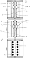
- the device 1 is a heating device which makes it possible to heat sheets in three different zones or to keep them at temperature.
- the zones can be formed in a furnace that structurally forms a unit, but the zones can also be arranged structurally separate from one another.
- the transport from the zones to each other or into zone 1 or out of zone 3 is usually carried out with blank carriers that are inserted into the respective zones with grippers or within the zones with known drives.
- a clocked movement adapted to the press cycle is preferred.
- Zone 1 is a preheating zone with rapid heating, with jacketed radiant tubes 2 (or open flames) acting on the board 3 in the preheating zone.
- the zone temperature here is approx. 1,300 ° C, as such a high zone temperature ensures that the boards are quickly heated to around 600 ° C in 10 seconds.
- the zone temperature can be selected to be somewhat lower, so that a board temperature of 600 ° C is reached after 20 seconds, but two boards are heated up in zone 1 at the same time. After the boards have been heated up in zone 1, they are transferred to zone 2.
- Zone 2 is the austenitizing zone, with electrical heating modules 4 in the austenitizing zone, which are connected to the blank are adapted, act on the board and bring about the temperature from the existing at least 600 ° C of the board to 850 ° C with a heating rate of> 10 K / s.
- the zone temperature is set to around 1,200 ° C.
- the electrical heating modules 4 can be adapted to the board via the number and density of the meanders, in particular existing laser welds, differences in sheet metal thickness or different emissivities of the surfaces of the boards.
- cooling inserts or cooling elements 5 are provided.
- the cooling inserts or cooling elements are arranged in such a way that the areas that are to remain more ductile do not reach the austenitizing temperature in an effective way.
- this can also be done by optionally existing shields, which z. B. can be formed from fiber composite components, or shielding plates are guaranteed.
- zone 2 Due to the high zone temperatures in zone 1 and zone 2, it is particularly preferred that the boards only spend the time in these zones that is necessary to reach the target temperature of the board, but not remain in these zones, otherwise an undesirable one Overheating can take place. However, this can be reduced in zone 2 by regulating the electrical heating modules.
- Zone 3 which can optionally be present, is a holding zone whose structure is comparable or identical to zone 2, but has a significantly lower zone temperature (approx. 950 ° C), which is suitable, taking into account the heat transfer, between the electrical heating modules on the one hand and the cooling elements on the other hand via the furnace atmosphere on or from the board, the preset temperatures with which the board left zone 2 and / or the temperature profile with which the board left zone 2 , to keep.
- zone temperature approximately 950 ° C
- the blank can also be cooled in a controlled manner in zone 3, provided that a preset temperature profile is maintained and no transformation takes place.
- Zone 3 can be suitable for compensating for cycle differences between Zone 1 and Zone 2 on the one hand and the press on the other.
- zone 3 in particular, can also have several positions in which the blanks can be held until they are reshaped.
- the zones 1, 2 and 3 can have a coupled transport system or individual transport systems, whereby the coupling can be of a mechanical as well as a control type.
- the heating rate in the first zone is up to around 600 ° C> 25 K / s, above 600 ° C > 10 K / s, so that the basic heating of the board takes place very quickly.
- the heating rate of the blank in the second zone is usually somewhat lower and is> 10 K / s, at which the austenitizing temperature is reached.
- the heating rate is less than 10 K / s and in particular the heating rate can in fact not be present there and only thermal homogenization and holding of the board take place.
- the device has at least two contact plates in the first zone and / or in the second zone and / or in the third zone.
- a sheet metal part to be treated is arranged between two contact plates in order to bring it to the necessary temperature.
- the first, the second and / or the third zone are then designed as radiant ovens.
- the two contact plates can then, for example, be arranged on tips formed on firebricks, which are normally provided for receiving sheet metal parts.
- an upper-side and a lower-side contact plate can be arranged in such an oven, so that they are heated to the desired temperature.
- the shape and geometry of the upper and lower plates correspond approximately to the sheet metal part to be heated.
- the steel plates are made from hot-work steel.
- the contact plates can also be arranged outside the radiant furnace.
Landscapes
- Engineering & Computer Science (AREA)
- Chemical & Material Sciences (AREA)
- Mechanical Engineering (AREA)
- Thermal Sciences (AREA)
- Physics & Mathematics (AREA)
- Crystallography & Structural Chemistry (AREA)
- Materials Engineering (AREA)
- Metallurgy (AREA)
- Organic Chemistry (AREA)
- General Engineering & Computer Science (AREA)
- Combustion & Propulsion (AREA)
- Heat Treatment Of Articles (AREA)
- Heat Treatments In General, Especially Conveying And Cooling (AREA)
- Heat Treatment Of Strip Materials And Filament Materials (AREA)
Description
- Die Erfindung betrifft ein Verfahren zum Aufheizen von Stahlblechen, insbesondere Stahlblechen, die anschließend einem Warmumform- und Härteschritt unterzogen werden.
- Es ist bekannt, dass Stahlbleche, die einem Warmumformschritt und einer Abschreckhärtung unterzogen werden sollen, zunächst - zumindest teilbereichsweise - auf eine Austenitisierungstemperatur erhitzt werden müssen, um eine Umwandlung des Austenits in Martensit und damit die Erzeugung eines gehärteten Gefüges zu ermöglichen.
- Hierzu muss das Gefüge insbesondere über den sogenannten AC3-Punkt des Stahlmaterials erhitzt werden.
- Aus der
WO 2013/000001 A1 ist ein Verfahren zum Erwärmen eines Formbauteils für ein anschließendes Presshärten sowie Durchlaufofen zum bereichsweisen Erwärmen eines auf eine vorgegebene Temperatur vorgewärmten Formbauteils auf eine höhere Temperatur bekannt. - Hierin wird ausgeführt, dass Härtegefüge, die bei austenitischen Stählen zu Zugfestigkeiten von über 1.500 MPa bei einer Dehnung im Bereich von 6 % führen können, häufig nur in Teilbereichen des Werkstückes notwendig sind, während in anderen Bereichen höhere Dehnungen von beispielsweise 15 % bis 17 % gefordert sind. Dementsprechend soll gemäß dieser Schrift ein Verfahren zum Erwärmen eines Formbauteiles auf unterschiedliche Temperaturen so ausgestaltet werden, dass trotz eines kontinuierlichen Durchlaufs durch eine Erwärmungseinrichtung die Formbauteile eine für das anschließende Presshärten erforderliche Wärmebehandlung mit einer verbesserten Temperaturführung besitzen. Hierfür schlägt dieses Dokument vor, dass das Formbauteil während seiner Förderung durch ein Heizelementfeld mit Hilfe bezüglich der Förderrichtung in Längs- und Querreihe angeordneten, zumindest gruppenweisen mit unterschiedlicher Heizleistung ansteuerbaren Heizelementen derart unterschiedlich erwärmt wird, dass Teile des Blechs einer Austenitisierungstemperatur erreichen, während andere Teile des Blechs diese nicht erreichen. Entsprechend dieser Maßnahme sollen Heizelemente mit unterschiedlicher Heizleistung angesteuert werden können, wobei mit der Möglichkeit Heizelemente sowohl entlang von Längsreihen als auch entlang von Querreihen zumindest gruppenweise voneinander unabhängig anzusteuern, auf die Temperatur der Formbauteile in einem in Förderrichtung verlaufenden Längsstreifen während der Bauteilförderung Einfluss genommen werden kann, um im Bereich solcher Längsstreifen vorgegebene Temperaturniveaus nicht nur zu erreichen sondern auch halten zu können. Zudem können auch entlang gewünschter Längsreihen ansteuerbare Kühleinrichtungen in Förderrichtung die Bauteile streifenförmig abkühlen.
- Aus der
DE 10 2012 001 742 A1 ist eine Vorrichtung zum Erwärmen von Blechwerkstücken für ein nachfolgendes Warmumformen und insbesondere Presshärten bekannt. Diese Vorrichtung soll die mit Rollenherdöfen einhergehenden Nachteile nicht oder zumindest nur in einem verminderten Umfang aufweisen und mit flexibel unterschiedlichen Erwärmungsanforderungen gehandhabt werden können. Hierzu soll die Vorrichtung mehrere Wärmstationen aufweisen, wobei eine erste Wärmstation vorhanden sein soll mit einer induktiven bzw. induktiv betriebenen Erwärmungseinrichtung, in der die Blechwerkstücke ohne zu verweilen schnell auf eine vorgegebene Temperatur erwärmt werden können, eine zweite Wärmstation, in der die Blechwerkstücke verweilen und dabei auf eine vorgegebene Temperatur erwärmt oder abgekühlt werden oder auf einer bestimmten Temperatur gehalten werden und eine dritte Wärmstation, in der die Blechwerkstücke verweilen und dabei auf eine vorgegebene Temperatur erwärmt, abgekühlt oder gehalten werden können. Die erste Wärmstation soll aufgrund des induktiven Erwärmungsprinzips ein schnelles und zielgerichtetes Erwärmen der Blechwerkstücke ermöglichen, wobei die erste Wärmstation vorzugsweise als Durchgangsstation ausgebildet ist und die zu erwärmenden Blechstücke einzeln oder gegebenenfalls auch zu mehreren und ohne nennenswerte Verweilzeit durch die erste Station durchgeführt werden, wobei die Erwärmung per Längs- oder Querfeldinduktion erfolgen kann. Die zweite und dritte Wärmstation können je nach Erwärmungsanforderungen in unterschiedlicher Art und Weise betrieben werden, wobei die zweite oder dritte Wärmestation wenigstens eine elektrisch betriebene und wenigstens eine mittels Brennstoffverbrennung betriebene Erwärmungseinrichtung besitzt. Die zweie Wärmestation soll hierbei als Nichtdurchgangsstation ausgebildet sein, während die dritte Wärmestation bevorzugt als Durchgangsstation ausgebildet ist. Zum Durchführen bzw. Durchleiten der zu erwärmenden Blechwerkstücke soll eine Hauptgasse vorgesehen sein, in der die dritte Wärmestation angeordnet ist, und zumindest eine Nebengasse, in der die erste und zweite Wärmestation angeordnet sind, wobei die Hauptgasse und die Nebengasse einen Kreuzungsbereich besitzen mit wenigstens einer Weiche für die Übergang der Blechwerkstücke von einer Gasse in die andere Gasse. Bevorzugt ist die zweite Wärmestation als nichtdurchgängige Station ausgebildet, insbesondere ist die zweite Wärmestation als Stapelofen ausgebildet, bzw. besitzt einen Stapelofen. - Aus der
DE 10 2009 019 496 A1 ist eine Vorrichtung bekannt, die drei aufeinander folgende Wärmestationen umfasst, welche von zu erwärmenden Blechwerkstücken in Folge bzw. nacheinander durchlaufen werden. Die erste Wärmestation besitzt dabei eine induktive Heizeinrichtung, mit der die zu erwärmenden Blechstücke schnell auf eine hohe Temperatur von bis zum mehreren 100 °C erwärmt werden. Anschließend werden die auf diese Weise angewärmten Blechwerkstücke den nachgeschalteten Wärmestationen zugeführt. - Aus der
DE 10 2009 051 157 B4 ist ein Verfahren zum Erwärmen eines Bauteiles für eine Warmumformung bekannt, bei welchem das Bauteil in einem Ofen auf eine Solltemperatur erwärmt wird, wobei der Ofen als Kammerofen ausgeführt ist und die Innentemperatur des Ofens zu jedem Zeitpunkt des Erwärmens über der Solltemperatur des Bauteiles liegt, wobei das Bauteil bei Erreichen der Solltemperatur aus dem Ofen entnommen wird ohne die Übertemperatur des Ofens anzunehmen. Hierbei soll das Verfahren zum Erwärmen eines Bauteiles für eine anschließende Warmumformung dahingehend verbessert werden, dass lange Erwärmungszeiten im Ofen verringert und die Stellfläche der Ofenanlage erheblich reduziert wird. - Aus der
DE 10 2010 017 905 A1 ist ein Verfahren zur Warmblechumformung bekannt, bei dem die Warmblechumformung durch die Erwärmung eines Bleches in einem ersten Schritt durch induktive Erwärmung mittels einer ersten Induktionserwärmungsvorrichtung auf eine Temperatur kleiner oder gleich der Curie-Temperatur erfolgt und in einem zweiten Schritt die Erwärmung auf Temperaturen > 800 °C mittels konventioneller Erwärmung in einem Ofen oder mittels induktiver Erwärmung in einem zweiten von der ersten verschiedenen Induktionserwärmungsvorrichtung erfolgt. Bei dem Verfahren kann die Erwärmung im ersten Schritt in zwei Unterschritten erfolgen, wobei in einem ersten Unterschritt das Blech auf eine erste Temperatur erhitzt wird und in einem zweiten Unterschritt das Blech bei einer Temperatur um mehr als 70 K niedriger als die erste Temperatur gehalten werden kann. Hiermit soll ein homogenes Aufschmelzen einer AlSi-Schutzschicht ermöglicht werden. Im ersten Schritt kann hierbei die Schutzschicht auf dem Blech vollständig aufgeschmolzen werden, wobei die Temperatur hier nahe der Curie-Temperatur liegt, also bei 710 °C bis 770 °C. Im zweiten Unterschritt kann ein Diffusionsvorgang erfolgen, wobei dieser für AlSi zwischen 600 °C und 650 °C liegt. - Aus der
DE 10 2009 019 573 A1 sind ein Ofen und ein Verfahren zum Erwärmen wenigstens eines Werkstückes bekannt, wobei ein Werkstück mittels eines an eine Transporteinrichtung gekoppelten Werkstückträgers von einem Eingangsbereich zu einem Ausgangsbereich des Ofens transportiert wird. Der Ofen umfasst zwei beheizbare Kammerbereiche, die über- oder auch nebeneinander angeordnet sind. Der Eingangs- und der Ausgangsbereich des Ofens sind ebenfalls über- oder nebeneinander angeordnet. Das zu erwärmende Werkstück wird auf einem Werkstückträger von der Transporteinrichtung erst durch den ersten und dann durch den zweiten Kammerbereich transportiert, dabei ist die Transportrichtung der Werkstückträger im ersten Kammerbereich entgegengesetzt zur Transportrichtung im zweiten Kammerbereich. - Aus der
EP 1 830 147 B1 ist ein Mehrkammerdurchlaufofen mit Schutzgasbetrieb und Verfahren zum oxidfreien Erwärmen von verzinkten Werkstücken bekannt, wobei hierdurch ein zunderfreies Erwärmen von verzinkten Werkstücken in einem Durchlaufofen sichergestellt werden soll. Der Ofen ist hierbei in mehrere Kammerbereiche aufgeteilt, in denen jeweils über Einspeisepunkte Schutzgasgemische mit vorzugsweise unterschiedlicher Zusammensetzung eingespeist werden, wobei die Zusammensetzung des Schutzgases an die Temperatur der Werkstücke in dem jeweiligen Ofenbereich angepasst ist. In dem letzten Kammerbereich wird dabei das Schutzgasgemisch mit dem geringsten Sauerstoffanteil eingespeist. Der Durchlaufofen weist zwischen den einzelnen Kammerbereichen entsprechende Schutzgasführungssysteme, vorzugsweise in Form von Trennwänden mit Öffnungen, auf, durch die der Gesamtstrom des Schutzgases so geführt wird, dass eine Konvektionswalze durch den gesamten Durchlaufofen verhindert wird und die Geschwindigkeit des Schutzgasstromes durch den Durchlaufofen höher ist als die Rückdiffusionsgeschwindigkeit. Das Schutzgasgemisch wird durch Teilverbrennung eines Kohlenwasserstoffluftgemisches in einem Edelmetallkatalysator erzeugt. - Aus der
DE 10 2012 104 537 A1 sind eine Ofenanlage und ein Verfahren zum Betreiben derselben bekannt, wobei Leichtmetallbauteile durch die Ofenanlage befördert werden und innerhalb der Ofenanlage mit einer Luft- oder Gasströmung erwärmt und gegebenenfalls abgekühlt werden. - Aus der
DE 10 2010 010 156 A1 ist ein Verfahren zur Herstellung eines Formteiles mit mindestens zwei Gefügebereichen unterschiedlicher Duktilität bekannt, wobei hierbei die Behandlung und Formung von entsprechenden Halbzeugen oder Platinen im Taktrhythmus des Presshärtewerkzeuges ohne Beeinflussung der Durchlaufgeschwindigkeit durch den Durchlaufofen ermöglicht wird und hierbei das Halbzeug nach Durchlauf durch den Durchlaufofen mit dem zweiten Teilbereich in eine Kammer eines Zwischenspeichers eingelegt wird, der den zweiten Teilbereich auf der Austenitisierungstemperatur hält, während der erste Teilbereich aus der Kammer des Zwischenspeichers vorragt und dieser vorragende Bereich mit Luft auf die Temperatur gekühlt wird, bei welcher das ferritische Gefüge gebildet wird. - Allgemein ist festzustellen, dass das Presshärten eine sehr anspruchsvolle Technik ist, bei der es darauf ankommt, die fertig aufgeheizten Platinen oder Halbzeuge zum richtigen Zeitpunkt in das Werkzeug einzulegen, zu pressen, dadurch abzukühlen und gleichzeitig zu härten.
- Zudem ist es wichtig, dass die Bauteile zwar in den zu härtenden Bereichen oder vollständig austenitisiert sind, es ist jedoch nicht angestrebt die Bauteile länger als notwendig in einem Ofen zu lassen.
- Während viele Öfen als Durchlauföfen ausgebildet sind, also kontinuierlich beschickt und entladen werden können, wird die Presse getaktet betrieben, so dass die Abstimmung der Beschickung und Entnahme des Ofens einerseits, der Ofenverweildauer andererseits und der Taktung der Presse sehr anspruchsvoll ist.
- Insgesamt ist es wünschenswert, dass bei einer Blechstärke von 1 mm bis 2 mm, maximal 0,8 mm bis 3 mm, sowie einer Taktzeit von 10 Sekunden und einer Zieltemperatur der Platine von 900 °C bei ca. 5 Sekunden Haltezeit eine Homogenität von +/- 15 °C über die Platine erreicht wird.
- Die im Stand der Technik genannten Erwärmungsmethoden sind insbesondere konduktiv, induktiv oder Wärmestrahlung, insbesondere durch offene Gasflammen. Es hat sich gezeigt, dass keine dieser Erwärmungsformen tatsächlich den Anforderungen über den gesamten Prozess voll genügt.
- Bekannte Öfen zum Strahlungserwärmen sind beispielsweise Kettenträgeröfen, Rollenherdöfen, Hubschrittförderöfen und Mehrkammeröfen.
- Bei den aus dem Stand der Technik bekannten Verfahren und Vorrichtungen zur Strahlungserwärmung von Bauteilen sind in der Regel relativ lange Ofenzeiten notwendig, um die Bauteile auf die gewünschte Temperatur aufzuheizen.
- Weiterhin wird bei derartigen Erwärmungsarten entweder Schutzgas verwendet oder Sauerstoff kann ungehindert die Bauteiloberfläche kontaktieren.
- Bei verzinkten Bauteilen kommt es aufgrund der langen Ofenzeiten, wie sie z.B. in Strahlungsöfen notwendig sind, zu verschiedenen Nachteilen. Diese Nachteile bestehen darin, dass sich die Gammaphase relativ schnell auflöst, der Fe-Gehalt steigt und das elektrochemische Potenzial steigt. Zudem sind die Prozessfenster zeitlich begrenzt. Aufgrund der zu einem wirtschaftlichen Betrieb notwendigen kurzen Taktzeit werden häufig relativ lange Öfen verwendet, die mit mehreren Teilen nacheinander beschickt werden. Kommt es zu Problemen bzw. Störungen in der Presse oder im Ofen erhöht sich dadurch der Ausschuss, da für sämtliche der im Ofen befindlichen zahlreichen Teile die Prozessfensterobergrenze überschritten wird..
- Wenn es bei verzinkten Bauteilen zu einer starken Oxidbildung kommt, müssen diese Teile im Anschluss gereinigt werden.
- Wird hingegen eine sauerstofffreie Atmosphäre bei verzinkten Bauteilen verwendet, kommt es meist zu einem Abbrand, da sich keine (dünne) Oxidschicht bilden kann.
- In der
EP 2 014 777 B1 sind ein Verfahren sowie eine Vorrichtung zur thermischen Behandlung von Metallblech offenbart. Hierbei ist vorgesehen, einen Metallkörper in einem ersten Verfahrensschritt zu erwärmen und in einem anschließenden Verfahrensschritt mit mindestens einer Kontaktplatte in Kontakt zu bringen. Dabei besitzt die Kontaktplatte eine gegenüber dem Metallkörper niedrigere Temperatur. Durch die niedrigere Temperatur der Kontaktplatten wird der Metallkörper nach dem Erwärmen gekühlt. Dabei soll diese Kühlung aufgrund der Kontaktplatten hinsichtlich der Temperaturkontrolle gut steuerbar sein. - Aus der
DE 10 2011 053 672 A1 gehen ein Verfahren sowie eine Anordnung zum Erwärmen einer Metallplatine hervor. Hierbei ist vorgesehen, eine Metallplatine in einer Heizvorrichtung zu erwärmen, wobei die Heizvorrichtung wenigstens ein unteres Kontaktelement und zumindest ein oberes Kontaktelement aufweist, so dass die Metallplatine zwischen den an ihre Kontur angepassten Kontaktelementen durch Zufuhr von Heizenergie auf eine Temperatur von 200°C bis 450°C erwärmt wird. - In der
DE 10 2011 102 167 A1 sind ein Verfahren zur Herstellung eines Formbauteils mit mindestens zwei Gefügebereichen unterschiedlicher Duktilität sowie eine Erwärmungseinrichtung offenbart. Gemäß diesem Verfahren soll eine Platine in einer Erwärmungseinrichtung derart mit zumindest einer mindestens zwei Heizsegmente aufweisenden Heizplatte kontaktieren, dass das erste auf eine Temperatur A eingestellte Heizsegment einen ersten Bereich der Platine auf eine Temperatur A und das zweite, auf eine Temperatur B eingestellte Heizsegment den zweiten Bereich der Platine auf eine Temperatur B erwärmt, wobei die Erwärmung des ersten Bereichs und des zweiten Bereichs der Platine jeweils durch Wärmeleitung erfolgt. - Aus der
EP 2 182 081 A1 gehen ein Verfahren sowie eine Vorrichtung zur thermischen Behandlung eines beschichteten Stahlkörpers hervor. Hierbei ist vorgesehen, einen Stahlblechkörper vor einem Warmumformprozess mit mindestens einer ersten Kontaktplatte mit mindestens einem ersten Flächenabschnitt des Stahlblechkörpers in Kontakt zu bringen und mindestens eine zweite Kontaktplatte mit mindestens einem zweiten Flächenabschnitt des Stahlblechkörpers in Kontakt zu bringen. Während der Kontaktierung soll eine Kontaktplatte eine gegenüber dem Stahlblechkörper höhere Temperatur aufweisen. - In der
EP 2 237 639 A1 sind eine Vorrichtung und ein Verfahren zum Erwärmen eines Körpers beschrieben. Hierbei ist eine Kontaktplatte, die zumindest zwei Heizelemente aufweist, vorgesehen, um dem zu erwärmenden Körper zu kontaktieren. - Aus der
EP 2 395 116 A2 geht eine Vorrichtung zum Erwärmen von Stahlplatten hervor. Mittels dieser Vorrichtung soll es möglich sein, mit einer Kontaktplatte unterschiedliche Bereiche der Stahlplatte auf unterschiedliche Temperaturen aufzuheizen. - Aus der
JP 2007-245196 A JP 2009-095869 A - In der
WO 2010/048950 A1 ist ein Verfahren zur thermischen Behandlung eines beschichteten Stahlblechkörpers beschrieben. Gemäß diesem Verfahren ist vorgesehen, dass mindestens eine Kontaktplatte zu Erwärmen des Stahlblechkörpers eine höhere Temperatur während der Kontaktierung von oberhalb Ac3, insbesondere eine Temperatur zwischen 20°C und 250°C von Ac3 aufweist, so dass eine Austenitisierung des Stahlblechkörpers erfolgt. - Aus der
WO 2012/045647 A1 sind ein Verfahren sowie ein Ofen zum Behandeln von Werkstücken beschrieben. Dabei soll ein Werkstück in dem Ofen von wenigstens zwei Heizelementen erwärmt werden. Insbesondere weisen die Heizeinheiten beheizbare Druckstempel auf. - Aufgabe der Erfindung ist es, ein Verfahren zum Aufheizen von Stahlblechen zum Zwecke der Warmumformung und Härtung zu schaffen, mit der diese zuverlässig und nachvollziehbar auf die notwendige Temperatur gebracht werden können.
- Die Aufgabe wird mit einem Verfahren mit den Merkmalen des Anspruchs 1 gelöst.
- Grundsätzlich ist das Verfahren ein diskontinuierliches bzw. getaktetes Verfahren, so dass z. B. kein Rollenherd oder Durchlaufofen grundsätzlich verwendet wird. Die Heizeinrichtung bzw. der Ofen umfasst mindestens zwei Stationen, es können jedoch auch zwei baulich getrennte Öfen verwendet werden, wobei die Zonen bei einer baulichen Einheit z. B. durch Schamotte, Isolierplatten, Trennbleche oder ähnlichen Elementen abgeschirmt sind.
- Hierbei werden spezifische Erwärmungsarten verwendet, wobei die Erwärmung in der Station 1 induktiv, über Plattenerwärmung, über Strahlrohre oder Gasbrenner und in der Station 2 über Strahlrohre, Gasbrenner oder Platten, jedoch keinesfalls Induktion erfolgt. Die Aufheizrate des Blechs in Station 1 ist von Raumtemperatur bis 600 °C > 25 K/s, über 600 °C bis kleiner blechspezifische AC3 > 10 K/s und die Aufheizrate des Blechs in Station 2 ist > 10 K/s.
- Alle Aufheizraten in dieser Anmeldung beziehen sich auf die durchschnittliche Heizrate über den angegebenen Temperaturbereich.
- Das Blech ist ein zinklegierungsbeschichtetes Blech, wobei das Blech aus einem Bor-Mangan-Stahl besteht.
- Da sich die Emissivität von reinen Zinkbeschichtungen bzw. reine Schmelztauchbeschichtungen während des Erwärmens ändert und damit auch das Verhalten bezüglich der Wärmeaufnahme, wird nach der Erfindung bevorzugt galvannealed Blech (ZF) eingesetzt, weil es seine Emissivität zu einem geringeren Ausmaß ändert.
- Insbesondere werden die Bleche einem sogenannten direkten Prozess zugeführt, d. h. die Bleche werden nach dem Erwärmen direkt umgeformt und gehärtet. Bevorzugt bestehen diese Bleche hierbei aus sogenannten Bor-Mangan-Stählen, wie den verbreiteten 22MnB5, jedoch sind auch andere geeignete abschreckhärtbare Stahlsorten denkbar.
- Grundsätzlich besteht die Vorrichtung aus einer Vorheizzone, einer Austenitisierungszone und einer Homogenisierungs- und Haltezone. Theoretisch wäre auch die Verwendung von vorgewärmten Platinen aus z. B. Durchlaufofen denkbar.
- In der Zone 1 wird mit einer Aufheizrate von beispielsweise Raumtemperatur bis ca. 600 °C > 25 K/s über ca. 600 °C mit einer Aufheizrate von > 10 K/s auf eine Temperatur aufgeheizt, die unter der AC3-Temperatur des Stahlwerkstoffes liegt, d. h. dass keine Austenitisierung stattfindet.
- Die zweite Zone ist die Austenitisierungszone, bei der die Bleche auf zumindest teilbereichsweise ca. 900 °C, bevorzugt 850 °C aufgeheizt werden, mit einer Rate, die > 10 K/s beträgt.
- In der dritten Zone werden die Bleche bei 850 °C bis 950 °C, bevorzugt 900 °C gehalten.
- In den Zonen 2 und 3 kann eine elektrische Heizung bevorzugt durchgeführt werden, mit Kühleinsätzen, wobei in der Zone 3 optional auch ohne zusätzliche Energiezu- und -abfuhr gearbeitet werden kann, wenn sich bei dem Prozess herausstellt, dass die Bleche mit ausreichender Wärme aus der Austenitisierungszone gelangen.
- Mit einer Aufheizrate > 25 K/s werden die Bleche einem ausgesprochenem Schnellerwärmen ausgesetzt, wobei, wie bereits ausgeführt, insbesondere feuerverzinktes Material (Z) für die Schnellerwärmung mittels Strahlung ungeeignet ist, da die Emissivität sich sprunghaft ändert. Dies gilt jedoch nicht für galvannealed Beschichtungen (ZF).
- In der Zone 1, der Vorheizzone, werden beispielsweise Mantelstrahlrohre oder offene Flammen bevorzugt verwendet, wobei die Temperatur der Zone ca. 1.300 °C beträgt, so dass die Platine bis etwa 600 °C in rund 10 Sekunden erhitzt wird.
- Alternativ kann die Zonentemperatur ca. 1.100 °C betragen, so dass 600 °C Platinentemperatur nach etwa 20 Sekunden erreicht werden, wobei zwei Platinen jeweils gleichzeitig in der Zone 1 vorgehalten werden können.
- Alternativ kann in Zone 1 mittels eines Längsfeldinduktors die Platine von Raumtemperatur auf Curie Temperatur erwärmt werden.
- Bevorzugt wird in der Zone 2, der Austenitisierungszone, ein elektrisches Heizmodul verwendet, welches allerdings an die Platinenform angepasst sein muss.
- Tailored parts und sogenannte tailored property parts bzw. partiell gehärtete Platinen können durch bauteilspezifische Optimierung der Meander der Heizeinrichtung und gegebenenfalls Kühleinsätze realisiert werden.
- In dieser Zone werden Zonentemperaturen von 1.000 °C bis 1.400 °C bevorzugt 1.100 °C bis 1.300 °C vorgehalten, um die Platine von rund 600 °C auf ca. 850 °C in etwa 10 Sekunden zu erhitzen.
- In der Haltezone sind die technischen Ausführungen im Wesentlichen der Zone 2 entsprechend, wobei jedoch die Zonentemperatur mit rund 950 °C deutlich niedriger ist.
- Um bei tailored property parts bzw. partiell gehärteten Formteilen Bereiche, die ungehärtet bleiben sollen, d. h. nicht die AC1 Temperatur überschreiten, zu erzielen, können diese beim Durchgang durch die Heizeinrichtung abgeschirmt werden, z. B. mit am Platinenträger befestigten Faserverbundkeramikplatten.
- Unterschiedliche Temperaturen über die Platine lassen sich hierbei in den elektrisch beheizten Zonen 2 und 3 inklusive durch Hinzunahme von Kühleinsätzen einprägen, wobei die Platine insbesondere die 600 °C bis 700 °C, maximal 750 °C in allen Bereichen behält, jedoch die Bereiche, die austenitisiert werden sollen, höher erhitzt sind.
- Bei tailored welded blanks, d. h. Blechen, die aus Blechen unterschiedlicher Dicke zusammengeschweißt sind, werden in Zone 1 die dünneren Bereiche eine höhere Temperatur annehmen als die dickeren Bereiche, wobei sich dieser Temperaturunterschied durch eine einseitige Abschirmung oder in den elektrisch beheizten Zonen 2 und 3 ausgleichen lässt.
- Erfindungsgemäß wurde erkannt, dass die Emissivität der Laserschweißnaht bei TWB-Blechen höher ist als die des Zinks, so dass in den Zonen 2 und 3 entsprechend durch Abschirmungen und/oder entsprechende selektive Beheizung auch die Bereiche der Laserschweißnaht mit der restlichen Platine homogenisiert werden können.
- Erfindungsgemäß soll die Wärmekapazität des Platinenträgers im Ofen möglichst niedrig ausfallen. Erfindungsgemäß sind deshalb Keramikteile, insbesondere Faserverbundkeramikteile, bevorzugt, da sie hohe Festigkeiten besitzen, verbunden mit einem günstigen Emissionsverhalten, einer geringen Wärmeleitfähigkeit und einer geringen volumetrischen Wärmekapazität.
- Sofern Abschirmbleche verwendet werden, müssen diese vor einer wiederholten Verwendung ausreichend abkühlen, sodass die abgeschirmten Platinenbereiche gesichert die AC3-Temperatur insbesondere AC1-Temperatur nicht erreichen, wobei es vorteilhaft ist eine im Verhältnis größere Zahl an Abschirmblechen vorzuhalten, so dass jeweils frische Abschirmbleche dem Schnellerwärmungsprozess zugeführt werden, während die verwendeten Abschirmbleche abkühlen gelassen werden. Alternativ können die Abschirmbleche auch aktiv gekühlt werden.
- Um die Stahlbleche zum Zwecke der Warmumformung und Härtung auf die notwendige Temperatur zu bringen kann alternativ zum vorstehend beschriebenen vorgesehen sein, dass in der ersten Zone und/oder in der zweiten Zone und/oder in der dritten Zone jeweils zumindest zwei Kontaktplatten vorgesehen sind.
- Hierbei ist vorgesehen dass ein zu behandelndes Blechteil zwischen diesen zumindest zwei Kontaktplatten angeordnet wird, um dieses auf die notwendige Temperatur zu bringen.
- Dabei ist erfindungsgemäß vorgesehen, die erste, die zweite und/oder die dritte Zone als Strahlungsöfen auszubilden. Die beiden Kontaktplatten können dann bspw. auf, auf Schamottsteinen ausgebildeten, Spitzen, die normalerweise zur Aufnahme von Blechteilen vorgesehen sind, angeordnet werden.
- Alternativ kann auch vorgesehen sein, dass die Kontaktplatte elektrisch oder mittels Strahlrohren erwärmt werden.
- Demgemäß sind eine oberseitige und eine unterseitige Kontaktplatte in einem solchen Ofen anordbar, so dass diese auf die gewünschte Temperatur aufgeheizt werden.
- Nachdem die obere und die untere Kontaktplatte die gewünschte Temperatur erreicht haben, ist dann vorgesehen, ein Blechteil im Bereich zwischen den beiden Kontaktplatten anzuordnen.
- Gemäß einer vorteilhaften Ausführungsform entsprechen die obere und die untere Kontaktplatte in ihrer Form und Geometrie in etwa dem zu erwärmenden Blechteil.
- Dadurch, dass die obere und die untere Kontaktplatte in etwa der Geometrie des Blechteils entsprechen, wird verhindert, dass die Kontaktplatten in den Bereichen, in denen sie nicht mit einem Blechteil kontaktieren, stark verzundern.
- Die Kontaktplatten können aus einem Warmarbeitsstahl ausgebildet sein.
- Die Blechteile werden mittels der Kontaktplatten über Wärmeleitung, Wärmestrahlung Strahlung und/oder Konvektion erhitzt.
- Bei der Erwärmung mittels Kontaktplatten im Strahlungsofen ergeben sich für verzinkte Blechteile diverse Vorteile.
- Das Erwärmen auf die gewünschte Temperatur erfolgt relativ schnell, wodurch eine Produktion von Stahlblechen im Prozesspunkt möglich ist. Dadurch verringert sich auch die Schrottquote. Zudem ist eine derartige Erwärmung von Stahlblechteilen äußerst energieeffizient, da Wärmeverluste verringert werden und idealerweise primär Energie zum Aufheizen verwendet werden kann. Zudem sind derartige Anlagen mit Strahlungsöfen und darin angeordneten Kontaktplatten zum Erwärmen von Stahlblechteilen äußerst kompakt und benötigen daher nur geringen Platz. Zudem sind derartige Anlagen äußerst kostengünstig ausgebildet.
- Weiterhin ergeben sich mit einer derartigen Anlage auch positive Auswirkungen auf die Schichtbildung. Durch die Oxidausbildung kann zumeist auf eine Reinigung der Blechteile verzichtet werden. Es ergibt sich ein verbesserter Schweißwiderstand. Zudem haftet Lack auf den Oberflächen der Bauteile durch die Oxidausbildung besser an. Überdies ergibt sich ein geringer Fe-Gehalt. Weiterhin ist eine gute elektrochemische Potenzialdifferenz zwischen Schicht und Substrat vorhanden. Weiterhin ergibt sich eine verbesserte Korrosionsschutzwirkung von verzinktem Vormaterial sowohl im direkten Prozess und auch im indirekten Prozess.
- Die Erfinder habe überraschenderweise herausgefunden, dass obwohl die Oberflächen der Stahlbleche mit den Kontaktplatten bedeckt sind die Zinkschicht im Ofen nicht abbrennt, da sich auch im Kontaktbereich zwischen dem Stahlblech und den Kontaktplatten genügend Oxide bilden.
- Dies ist darauf zurückführbar, dass die Oxide auf dem Stahlblech durch Reduktion von Fe-Oxiden auf der Oberfläche der aus Warmarbeitsstahl ausgebildeten Kontaktplatten entstehen.
- Auch im ungereinigten Zustand weisen derart behandelte Stahlblechteile geringe Übergangswiderstände auf.
- Mittels eines derartigen Verfahrens kann eine genau definierte Temperatur in die Bereiche des Stahlblechs eingebracht werden, die mit den Kontaktplatten kontaktieren. Auf diese Weise ist es möglich, die sich durch die thermische Behandlung einstellenden Werkstoffeigenschaften sehr exakt und homogen einzustellen.
- Eine derartige Erwärmung mittels Kontaktplatten in einem Strahlungsofen ist äußerst variabel einsetzbar, da sowohl die Temperatur der Kontaktplatte als auch die Zeit für die Kontaktierung zwischen Kontaktplatten und Metallblech nahezu beliebig einstellbar ist. Auf diese Weise kann ein erfindungsgemäßes Verfahren variabel an die gewünschten Parameter der thermischen Behandlung sowie an den zu behandelnden Werkstoff angepasst werden.
- Vorzugsweise ist vorgesehen, dass sich die Kontaktplatte und das zu behandelnde Stahlblech direkt berühren.
- In einer weiteren Ausführungsvariante kann ein anpressen der Kontaktplatten auf das Stahlblech mit einer Kraft von 0,01 bis 0,6 MPa insbesondere 0,1 bis 0,3 MPa vorgesehen sein. Dies verbessert den Wärmeübergang und daraus folgend die Aufheizgeschwindigkeit.
- Es können auch zwei oder mehr Kontaktplatten für eine Bauteiloberfläche vorgesehen sein um unterschiedliche Bereiche eines Stahlbleches mit unterschiedlichen Temperaturen zu behandeln.
- Die Erfindung wird anhand einer Zeichnung beispielhaft erläutert, die einzige Figur zeigt dabei stark schematisiert die Vorrichtung zum Durchführen des erfindungsgemäßen Verfahrens zum Erwärmen von Stahlblechplatinen in einem Querschnitt.
- Die Vorrichtung 1 ist eine Erwärmungsvorrichtung, welche es ermöglicht Bleche in drei unterschiedlichen Zonen aufzuheizen bzw. auf Temperatur zu halten. Hierbei können die Zonen in einem baulich eine Einheit bildenden Ofen gebildet sein, es können aber auch die Zonen baulich getrennt voneinander angeordnet sein. Der Transport von den Zonen zueinander bzw. in die Zone 1 hinaus oder aus der Zone 3 hinaus erfolgt üblicherweise mit Platinenträgern, die mit Greifern in die jeweiligen Zonen eingelegt werden oder innerhalb der Zonen mit an sich bekannten Vortrieben.
- Gleich ob die Platinenträger eingelegt werden oder angetrieben werden, wird eine getaktete an den Pressentakt angepasste Fortbewegung bevorzugt.
- Die Zone 1 ist eine Vorheizzone mit Schnellerwärmung, wobei in der Vorheizzone Mantelstrahlrohre 2 (oder offene Flammen) auf die Platine 3 einwirken. Die Zonentemperatur beträgt hierbei ca. 1.300 °C, da eine solch hohe Zonentemperatur eine schnelle Erwärmung der Platinen auf etwa 600 °C in 10 Sekunden sicherstellt.
- Alternativ kann die Zonentemperatur etwas niedriger gewählt sein, so dass eine Platinentemperatur von 600 °C nach 20 Sekunden erreicht wird, wobei jedoch zwei Platinen gleichzeitig in der Zone 1 aufgeheizt werden. Nachdem die Platinen in der Zone 1 aufgeheizt wurden, werden sie in die Zone 2 transferiert.
- Die Zone 2 ist die Austenitisierungszone, wobei in der Austenitisierungszone elektrische Heizmodule 4, welche an die Platinenform angepasst sind, auf die Platine einwirken und die Temperatur von den bestehenden mindestens 600 °C der Platine auf 850 °C mit einer Aufheizrate von > 10 K/s bewerkstelligen. Die Zonentemperatur ist hierbei auf etwa 1.200 °C eingestellt.
- Die elektrischen Heizmodule 4 können über die Anzahl und Dichte der Meander auf die Platine, insbesondere vorhandene Laserschweißnähte, Blechdickenunterschiede bzw. unterschiedliche Emissivitäten der Oberflächen der Platinen, angepasst sein.
- Um in Bereichen, in denen die Austenitisierungstemperatur nicht erreicht werden soll, dafür zu sorgen, dass die Platine sich nicht weiter aufheizt, sind Kühleinsätze bzw. Kühlelemente 5 vorhanden. Die Kühleinsätze bzw. Kühlelemente sind so angeordnet, dass die Bereiche, die duktiler verbleiben sollen, in wirkungsvoller Weise nicht die Austenitisierungstemperatur erreichen. Anstelle von Kühlelementen kann dies auch durch gegebenenfalls vorhandene Abschirmungen, die z. B. aus Faserverbundbauteilen gebildet sein können, oder Abschirmblechen gewährleistet werden.
- Aufgrund der hohen Zonentemperaturen in der Zone 1 und der Zone 2 ist es besonders bevorzugt, dass die Platinen lediglich die Zeit in diesen Zonen verbringen, die zur Erreichung der Zieltemperatur der Platine notwendig ist, jedoch nicht weiter in diesen Zonen verbleiben, da ansonsten eine unerwünschte Überhitzung stattfinden kann. Diese kann in Zone 2 allerdings durch die Regelung der elektrischen Heizmodule notfalls vermindert werden.
- Die Zone 3, welche optional vorhanden sein kann, ist eine Haltezone, welche vom Aufbau her mit Zone 2 vergleichbar bzw. identisch ist, jedoch eine deutlich niedrigere Zonentemperatur besitzt (ca. 950 °C), die dazu geeignet ist, unter Berücksichtigung des Wärmeübergangs, zwischen den elektrischen Heizmodulen einerseits und den Kühlelementen andererseits über die Ofenatmosphäre auf bzw. von der Platine die voreingestellten Temperaturen, mit denen die Platine die Zone 2 verlassen hat, und/oder das Temperaturprofil, mit dem die Platine die Zone 2 verlassen hat, zu halten.
- Hierbei kann, insbesondere bei umwandlungsverzögerten härtbaren Stählen in der Zone 3 auch eine Abkühlung der Platine in kontrollierter Weise erfolgen, sofern ein voreingestelltes Temperaturprofil erhalten bleibt und keine Umwandlung stattfindet.
- Die Zone 3 kann hierbei dazu geeignet sein Taktunterschiede zwischen Zone 1 und Zone 2 einerseits und der Presse andererseits auszugleichen. Hierzu kann insbesondere die Zone 3 auch über mehrere Positionen verfügen, in denen die Platinen bis zur Umformung entsprechend gehalten werden können.
- Die Zonen 1, 2 und 3 können über ein gekoppeltes Transportsystem oder einzelne Transportsysteme verfügen, wobei die Kopplung sowohl mechanischer als auch steuerungstechnischer Art sein kann.
- Als besonders bevorzugt hat es sich ergeben, in den zwei Stationen mit sehr hohen Aufheizraten zu arbeiten, wobei die Aufheizraten theoretisch gleich sein können, bevorzugt die Aufheizrate in der ersten Zone bis rund 600 °C > 25 K/s beträgt, über 600 °C > 10 K/s beträgt, so dass die Grundaufheizung der Platine sehr schnell vonstattengeht. Die Aufheizrate der Platine in der zweiten Zone ist üblicherweise etwas geringer und beträgt > 10 K/s, mit der die Austenitisierungstemperatur erreicht wird.
- In der optionalen dritten Zone ist die Aufheizrate geringer als 10 K/s und insbesondere kann die Aufheizrate dort faktisch nicht vorhanden sein und lediglich eine thermische Homogenisierung und ein Halten der Platine stattfinden.
- Um die Stahlbleche zum Zwecke der Warmumformung und Härtung auf die notwendige Temperatur zu bringen kann alternativ zum vorstehend beschriebenen vorgesehen sein, dass die Vorrichtung in der ersten Zone und/oder in der zweiten Zone und/oder in der dritten Zone jeweils zumindest zwei Kontaktplatten aufweist.
- Hierbei ist vorgesehen, dass ein zu behandelndes Blechteil zwischen zwei Kontaktplatten angeordnet wird, um dieses auf die notwendige Temperatur zu bringen.
- Die erste, die zweite und/oder die dritte Zone sind dann als Strahlungsöfen ausgebildet. Die beiden Kontaktplatten können dann bspw. auf, auf Schamottesteinen ausgebildeten, Spitzen, die normalerweise zur Aufnahme von Blechteilen vorgesehen sind, angeordnet werden.
- Demgemäß sind eine oberseitige und eine unterseitige Kontaktplatte in einem solchen Ofen anordbar, so dass diese auf die gewünschte Temperatur aufgeheizt werden.
- Nachdem die obere und die untere Kontaktplatte die gewünschte Temperatur erreicht haben, ist dann vorgesehen, ein Blechteil im Bereich zwischen den beiden Platten anzuordnen.
- Gemäß einer vorteilhaften Ausführungsform entsprechen die obere und die untere Platte in ihrer Form und Geometrie in etwa dem zu erwärmenden Blechteil.
- Die Stahlplatten sind aus einem Warmarbeitsstahl ausgebildet. Selbstverständlich können die Kontaktplatten auch außerhalb des Strahlungsofens angeordnet sein.
-
- 1
- Vorrichtung
- 2
- Mantelstrahlrohre
- 3
- Platine
- 4
- elektrische Heizmodule
- 5
- Kühleinsätze/Kühlelemente
Claims (7)
- Verfahren zum Aufheizen einer Platine oder einem vorgeformten Stahlblechbauteil zum Zwecke der Warmumformung und/oder der Abschreckhärtung, wobei die Erhitzung zumindest teilbereichsweise auf eine Temperatur oberhalb AC3 durchgeführt wird, wobei die Erhitzung der Platine als Schnellerwärmung durchgeführt wird und hierzu die Platine in einer ersten Zone mit einer durchschnittlichen Aufheizrate von > 25 K/s bis ca. 600 °C und über dieser Temperatur mit einer durchschnittlichen Aufheizrate von > 10 K/s auf maximal AC3-Temperatur erhitzt wird und anschließend in eine zweite Zone überführt wird, in der die in der ersten Zone vorerhitzte Platine zumindest teilbereichsweise auf Temperaturen über AC3 insbesondere > 850 °C erhitzt wird, wobei die Aufheizrate in der zweiten Zone > 10 K/s beträgt, wobei nach der Zone 2 eine dritte Zone vorhanden ist, welche als Homogenisierungs- und Haltezone ausgebildet ist, wobei die Aufheizrate dort < 10 K/s beträgt oder die Heizleistung so bemessen ist, dass eine kontrollierte Temperaturabnahme der Platine, jedoch ohne Unterschreitung der Umwandlungspunkte der austenitisierten Bereiche, oder ein Halten der Temperatur und des Temperaturprofils sichergestellt ist, wobei die Platine aus einem beschichteten Blech ausgebildet wird und das Blech ein zinklegierungsbeschichtetes Blech ist, wobei das Blech aus einem Bor-Mangan-Stahl besteht.
- Verfahren nach Anspruch 1, dadurch gekennzeichnet,
dass die erste Zone mit Mantelstrahlrohren oder offenen Flammen erhitzt wird. - Verfahren nach Anspruch 2, dadurch gekennzeichnet, dass die Zonentemperatur in der ersten Zone etwa 1.100 °C bis 1.300 °C beträgt.
- Verfahren nach einem der vorhergehenden Ansprüche, dadurch gekennzeichnet, dass die Zonentemperatur in der zweiten Zone etwa 1.000 °C bis 1.400 °C, bevorzugt 1.100 °C bis 1.300 °C beträgt.
- Verfahren nach Anspruch 1 oder 2, dadurch gekennzeichnet, dass die Platinen in der ersten Zone durch einen Längsfeldinduktor erhitzt werden.
- Verfahren nach Anspruch 1, dadurch gekennzeichnet, dass das Aufheizen einer Platine oder eines vorgeformten Stahlblechbauteil zum Zwecke der Warmumformung und/oder der Abschreckhärtung in der ersten Zone und/oder in der zweiten Zone und/oder in der dritten Zone mittels zumindest zweier Kontaktplatten erfolgt.
- Verfahren nach Anspruch 6, dadurch gekennzeichnet, dass eine zu behandelnde Platine oder ein vorgeformtes Stahlblechbauteil zwischen zwei Kontaktplatten angeordnet wird, um dieses auf die notwendige Temperatur zu bringen.
Applications Claiming Priority (2)
| Application Number | Priority Date | Filing Date | Title |
|---|---|---|---|
| DE102014110415.3A DE102014110415B4 (de) | 2014-07-23 | 2014-07-23 | Verfahren zum Aufheizen von Stahlblechen und Vorrichtung zur Durchführung des Verfahrens |
| PCT/EP2015/066634 WO2016012442A1 (de) | 2014-07-23 | 2015-07-21 | Verfahren zum aufheizen von stahlblechen und vorrichtung zur durchführung des verfahrens |
Publications (2)
| Publication Number | Publication Date |
|---|---|
| EP3172345A1 EP3172345A1 (de) | 2017-05-31 |
| EP3172345B1 true EP3172345B1 (de) | 2020-09-09 |
Family
ID=53835396
Family Applications (1)
| Application Number | Title | Priority Date | Filing Date |
|---|---|---|---|
| EP15749735.5A Active EP3172345B1 (de) | 2014-07-23 | 2015-07-21 | Verfahren zum aufheizen von stahlblechen |
Country Status (8)
| Country | Link |
|---|---|
| US (1) | US10612108B2 (de) |
| EP (1) | EP3172345B1 (de) |
| CN (1) | CN106715725A (de) |
| CA (1) | CA2955279C (de) |
| DE (1) | DE102014110415B4 (de) |
| ES (1) | ES2820764T3 (de) |
| MX (1) | MX2017001024A (de) |
| WO (1) | WO2016012442A1 (de) |
Families Citing this family (15)
| Publication number | Priority date | Publication date | Assignee | Title |
|---|---|---|---|---|
| DE102015215179A1 (de) * | 2015-08-07 | 2017-02-09 | Schwartz Gmbh | Verfahren zur Wärmebehandlung und Wärmebehandlungsvorrichtung |
| DE102016101975B4 (de) * | 2016-02-04 | 2017-10-19 | Voestalpine Metal Forming Gmbh | Vorrichtung zum Herstellen von gehärteten Stahlbauteilen und Verfahren zum Härten |
| EP4400608A2 (de) * | 2016-08-09 | 2024-07-17 | Autotech Engineering, S.L. | Zentrierung und selektive erwärmung |
| DE102016219579A1 (de) | 2016-10-10 | 2018-04-12 | Volkswagen Aktiengesellschaft | Verfahren zur Wärmebehandlung und Einrichtung zur Wärmebehandlung |
| WO2018115298A1 (en) * | 2016-12-22 | 2018-06-28 | Autotech Engineering A.I.E. | Method for heating a blank and heating system |
| DE102017120128A1 (de) * | 2017-09-01 | 2019-03-07 | Schwartz Gmbh | Verfahren zum Erwärmen eines metallischen Bauteils auf eine Zieltemperatur und entsprechender Rollenherdofen |
| CN107523668B (zh) * | 2017-09-01 | 2019-06-25 | 华菱安赛乐米塔尔汽车板有限公司 | 一种无镀层变强度钢复合材料 |
| DE102019115968A1 (de) * | 2018-12-17 | 2020-06-18 | CREMER Polyfour Entwicklungs- und Vertriebs-GmbH für Industrieöfen | Hubbalkendurchlaufofen und Verfahren zum Betrieb eines Hubbalkendurchlaufofens |
| ES2907102T3 (es) * | 2019-08-14 | 2022-04-21 | Automation Press And Tooling Ap & T Ab | Estación de calentamiento intermedia |
| DE102020103276A1 (de) * | 2020-02-10 | 2021-08-12 | Benteler Automobiltechnik Gmbh | Ofen zur partiellen Erwärmung von Metallbauteilen |
| DE102020116593A1 (de) * | 2020-06-24 | 2021-12-30 | AICHELIN Holding GmbH | Wärmebehandlungsanlage und Verfahren zur Herstellung von Formbauteilen |
| DE102020212465A1 (de) | 2020-10-01 | 2022-04-07 | Thyssenkrupp Steel Europe Ag | Verfahren zur Herstellung eines zumindest teilweise pressgehärten Stahlblechbauteils und zumindest teilweise pressgehärtetes Stahlblechbauteil |
| DE102020127057A1 (de) | 2020-10-14 | 2022-04-14 | Benteler Automobiltechnik Gmbh | Verfahren zur Herstellung einer Stahlplatine sowie Temperierstation |
| DE102020133462A1 (de) * | 2020-12-15 | 2022-06-15 | Schwartz Gmbh | Thermisches Behandeln von Bauteilen |
| DE112021007984A5 (de) * | 2021-07-16 | 2024-04-25 | Benteler Maschinenbau Gmbh | Mehrzonen-Heizverfahren, Heizvorrichtung und Verfahren zur Herstellung eines Kraftfahrzeugbauteils |
Family Cites Families (25)
| Publication number | Priority date | Publication date | Assignee | Title |
|---|---|---|---|---|
| US6180933B1 (en) * | 2000-02-03 | 2001-01-30 | Bricmont, Inc. | Furnace with multiple electric induction heating sections particularly for use in galvanizing line |
| KR100825975B1 (ko) | 2003-07-29 | 2008-04-28 | 뵈스트알파인 스탈 게엠베하 | 경화 강판 부품의 제조 방법 |
| ES2383964T3 (es) * | 2006-03-03 | 2012-06-27 | Schwartz, Eva | Horno de paso continuo de varias cámaras con funcionamiento de gas protector y procedimiento para el calentamiento libre de óxido de piezas de trabajo galvanizadas |
| JP4900908B2 (ja) | 2006-03-16 | 2012-03-21 | コマツ産機株式会社 | プレス成形のための加熱装置および方法 |
| DE102006027625B3 (de) | 2006-06-13 | 2007-08-09 | Benteler Automobiltechnik Gmbh | Ofenanlage und Warmformlinie |
| EP2014777B1 (de) | 2007-07-11 | 2013-01-09 | Neue Materialien Bayreuth GmbH | Verfahren sowie Vorrichtung zur thermischen Behandlung von Metallblech |
| JP4890416B2 (ja) | 2007-10-18 | 2012-03-07 | アイシン高丘株式会社 | ダイクエンチ工法におけるプレス加工装置及びプレス加工方法 |
| JP4812785B2 (ja) * | 2008-01-25 | 2011-11-09 | アイシン高丘株式会社 | 被加熱材の加熱装置及び加熱方法 |
| EP2182081B1 (de) | 2008-10-29 | 2014-01-22 | Neue Materialien Bayreuth GmbH | Verfahren zur thermischen Behandlung eines beschichteten Stahlblechkörpers |
| DE102009019573A1 (de) * | 2009-05-02 | 2010-11-11 | Messarius, Uwe | Ofen und Verfahren zum Erwärmen wenigstens eines Werkstückes |
| DE102009019496A1 (de) * | 2009-05-04 | 2010-11-18 | Braun, Elisabeth | Vorrichtung und Verfahren zur Erwärmung warm umzuformender Werkstücke |
| DE102009051157B4 (de) * | 2009-10-29 | 2011-09-22 | Benteler Automobiltechnik Gmbh | Kammerofen mit Übertemperatur |
| JP4840518B2 (ja) * | 2010-02-24 | 2011-12-21 | Jfeスチール株式会社 | 方向性電磁鋼板の製造方法 |
| DE102010010156A1 (de) * | 2010-03-04 | 2011-09-08 | Kirchhoff Automotive Deutschland Gmbh | Verfahren zur Herstellung eines Formteiles mit mindestens zwei Gefügebereichen unterschiedlicher Duktilität |
| DE102010017905B4 (de) * | 2010-04-21 | 2014-08-21 | TRUMPF Hüttinger GmbH + Co. KG | Verfahren und Induktionserwärmungsvorrichtung zur Warmblechumformung |
| JP2011255413A (ja) | 2010-06-11 | 2011-12-22 | Toyoda Iron Works Co Ltd | 鋼板の加熱装置、プレス成形品の製造方法、およびプレス成形品 |
| EP2439289B1 (de) | 2010-10-05 | 2016-09-28 | Schwartz GmbH | Verfahren und Ofen zum Behandeln von Werkstücken |
| DE102011102167A1 (de) | 2011-05-21 | 2012-11-22 | Volkswagen Aktiengesellschaft | Verfahren zur Herstellung eines Formbauteils mit mindestens zwei Gefügebereichen unterschiedlicher Duktilität und Erwärmungseinrichtung |
| BR112013029982A2 (pt) * | 2011-06-30 | 2017-01-31 | Ebner Ind Ges M B H | processo para aquecimento de um componente moldado para um subsequente endurecimento por pressão, bem como forno contínuo para o aquecimento regional de um componente moldado aquecido previamente para uma temperatura predeterminada a uma temperatura mais elevada |
| DE102011053672B4 (de) | 2011-09-16 | 2017-08-10 | Benteler Automobiltechnik Gmbh | Verfahren und Anordnung zum Erwärmen einer Metallplatine |
| CN103429775B (zh) * | 2011-12-16 | 2015-09-23 | Posco公司 | 具有优良磁性能的晶粒取向电工钢板的制备方法 |
| DE102012001742A1 (de) * | 2012-01-28 | 2013-08-01 | Volkswagen Aktiengesellschaft | Vorrichtung zum Erwärmen von Blechwerkstücken für ein nachfolgendes Warmumformen und insbesondere Presshärten |
| DE102012104537A1 (de) * | 2012-05-25 | 2013-11-28 | Benteler Automobiltechnik Gmbh | Ofenanlage sowie Verfahren zum Betreiben der Ofenanlage |
| CN104603298A (zh) * | 2012-09-03 | 2015-05-06 | 杰富意钢铁株式会社 | 连续退火设备的急速加热装置 |
| DE102012110649C5 (de) | 2012-11-07 | 2018-03-01 | Benteler Automobiltechnik Gmbh | Warmformlinie sowie Verfahren zur Herstellung eines warmumgeformten und pressgehärteten Kraftfahrzeugbauteils |
-
2014
- 2014-07-23 DE DE102014110415.3A patent/DE102014110415B4/de active Active
-
2015
- 2015-07-21 US US15/328,469 patent/US10612108B2/en active Active
- 2015-07-21 MX MX2017001024A patent/MX2017001024A/es unknown
- 2015-07-21 CA CA2955279A patent/CA2955279C/en active Active
- 2015-07-21 ES ES15749735T patent/ES2820764T3/es active Active
- 2015-07-21 EP EP15749735.5A patent/EP3172345B1/de active Active
- 2015-07-21 WO PCT/EP2015/066634 patent/WO2016012442A1/de active Application Filing
- 2015-07-21 CN CN201580051558.5A patent/CN106715725A/zh active Pending
Non-Patent Citations (1)
| Title |
|---|
| None * |
Also Published As
| Publication number | Publication date |
|---|---|
| CA2955279C (en) | 2021-10-19 |
| US10612108B2 (en) | 2020-04-07 |
| EP3172345A1 (de) | 2017-05-31 |
| MX2017001024A (es) | 2017-03-14 |
| ES2820764T3 (es) | 2021-04-22 |
| CN106715725A (zh) | 2017-05-24 |
| DE102014110415B4 (de) | 2016-10-20 |
| WO2016012442A1 (de) | 2016-01-28 |
| US20170218473A1 (en) | 2017-08-03 |
| DE102014110415A1 (de) | 2016-01-28 |
| CA2955279A1 (en) | 2016-01-28 |
Similar Documents
| Publication | Publication Date | Title |
|---|---|---|
| EP3172345B1 (de) | Verfahren zum aufheizen von stahlblechen | |
| EP2905346B1 (de) | Wärmebehandlungsverfahren | |
| EP2497840B2 (de) | Ofensystem zum partiellen Erwärmen von Stahlblechteilen | |
| EP2907881B2 (de) | Warmformlinie und Verfahren zur Herstellung von warmumgeformten Blechprodukten | |
| EP2427282B1 (de) | Vorrichtung und verfahren zur erwärmung warm umzuformender werkstücke | |
| EP3332041B1 (de) | Verfahren zur wärmebehandlung eines stahlblechbauteils und wärmebehandlungsvorrichtung dafür | |
| EP2411548A1 (de) | Verfahren zum herstellen partiell gehärteter stahlbauteile | |
| WO2011009769A1 (de) | Verfahren und vorrichtung zum energieeffizienten warmumformen | |
| EP2824216B1 (de) | Verfahren zur Herstellung eines durch Schmelztauchbeschichten mit einer metallischen Schutzschicht versehenen Stahlflachprodukts und Durchlaufofen für eine Schmelztauchbeschichtungsanlage | |
| EP1816219A1 (de) | Verfahren zur Wärmebehandlung von Stahlbändern mittels direkter Flammenbeheizung | |
| EP3652352B1 (de) | Verfahren und vorrichtung zur wärmebehandlung eines metallischen bauteils | |
| EP2806041A2 (de) | Anlage und Verfahren zum Warmumformen von Platinen | |
| AT15097U1 (de) | Wärmebehandlungsvorrichtung | |
| EP2883967B1 (de) | Verfahren und Vorrichtung zur Nachbehandlung eines gehärteten metallischen Formteils mittels elektrischer Widerstandserwärmung | |
| DE102011102167A1 (de) | Verfahren zur Herstellung eines Formbauteils mit mindestens zwei Gefügebereichen unterschiedlicher Duktilität und Erwärmungseinrichtung | |
| DE102016124539B4 (de) | Verfahren zum Herstellen lokal gehärteter Stahlblechbauteile | |
| EP2097544A1 (de) | Verfahren und vorrichtung zur wärmebehandlung von schweissnähten | |
| EP2920535B1 (de) | Rollenherdofen und verfahren zur wärmebehandlung von metallischen blechen | |
| EP2818571B1 (de) | Eindiffundieren von Aluminium-Silizium in eine Stahlblechbahn | |
| DE102017203784A1 (de) | Verfahren zur Herstellung, Wärmebehandlung und Warmumformung von Metallblechelementen | |
| DE102014104922B4 (de) | Vorrichtung und Verfahren zum Kühlen von Stahlblechplatinen | |
| EP3184655A1 (de) | Wärmebehandlungsofen sowie verfahren zur wärmebehandlung einer vorbeschichteten stahlblechplatine und verfahren zur herstellung eines kraftfahrzeugbauteils | |
| DE102015204652A1 (de) | Werkstückauflagesystemumrüstung |
Legal Events
| Date | Code | Title | Description |
|---|---|---|---|
| STAA | Information on the status of an ep patent application or granted ep patent |
Free format text: STATUS: THE INTERNATIONAL PUBLICATION HAS BEEN MADE |
|
| PUAI | Public reference made under article 153(3) epc to a published international application that has entered the european phase |
Free format text: ORIGINAL CODE: 0009012 |
|
| STAA | Information on the status of an ep patent application or granted ep patent |
Free format text: STATUS: REQUEST FOR EXAMINATION WAS MADE |
|
| 17P | Request for examination filed |
Effective date: 20170105 |
|
| AK | Designated contracting states |
Kind code of ref document: A1 Designated state(s): AL AT BE BG CH CY CZ DE DK EE ES FI FR GB GR HR HU IE IS IT LI LT LU LV MC MK MT NL NO PL PT RO RS SE SI SK SM TR |
|
| AX | Request for extension of the european patent |
Extension state: BA ME |
|
| DAV | Request for validation of the european patent (deleted) | ||
| DAX | Request for extension of the european patent (deleted) | ||
| STAA | Information on the status of an ep patent application or granted ep patent |
Free format text: STATUS: EXAMINATION IS IN PROGRESS |
|
| 17Q | First examination report despatched |
Effective date: 20180829 |
|
| RIN1 | Information on inventor provided before grant (corrected) |
Inventor name: KURZ, THOMAS Inventor name: SOMMER, ANDREAS Inventor name: STEGFELLNER, LEOPOLD Inventor name: KOLNBERGER, SIEGFRIED Inventor name: HASLMAYR, MICHAEL |
|
| GRAP | Despatch of communication of intention to grant a patent |
Free format text: ORIGINAL CODE: EPIDOSNIGR1 |
|
| STAA | Information on the status of an ep patent application or granted ep patent |
Free format text: STATUS: GRANT OF PATENT IS INTENDED |
|
| INTG | Intention to grant announced |
Effective date: 20200629 |
|
| GRAS | Grant fee paid |
Free format text: ORIGINAL CODE: EPIDOSNIGR3 |
|
| GRAA | (expected) grant |
Free format text: ORIGINAL CODE: 0009210 |
|
| STAA | Information on the status of an ep patent application or granted ep patent |
Free format text: STATUS: THE PATENT HAS BEEN GRANTED |
|
| AK | Designated contracting states |
Kind code of ref document: B1 Designated state(s): AL AT BE BG CH CY CZ DE DK EE ES FI FR GB GR HR HU IE IS IT LI LT LU LV MC MK MT NL NO PL PT RO RS SE SI SK SM TR |
|
| REG | Reference to a national code |
Ref country code: GB Ref legal event code: FG4D Free format text: NOT ENGLISH |
|
| REG | Reference to a national code |
Ref country code: AT Ref legal event code: REF Ref document number: 1311647 Country of ref document: AT Kind code of ref document: T Effective date: 20200915 Ref country code: CH Ref legal event code: EP |
|
| REG | Reference to a national code |
Ref country code: DE Ref legal event code: R096 Ref document number: 502015013425 Country of ref document: DE |
|
| REG | Reference to a national code |
Ref country code: IE Ref legal event code: FG4D Free format text: LANGUAGE OF EP DOCUMENT: GERMAN |
|
| REG | Reference to a national code |
Ref country code: LT Ref legal event code: MG4D |
|
| PG25 | Lapsed in a contracting state [announced via postgrant information from national office to epo] |
Ref country code: GR Free format text: LAPSE BECAUSE OF FAILURE TO SUBMIT A TRANSLATION OF THE DESCRIPTION OR TO PAY THE FEE WITHIN THE PRESCRIBED TIME-LIMIT Effective date: 20201210 Ref country code: FI Free format text: LAPSE BECAUSE OF FAILURE TO SUBMIT A TRANSLATION OF THE DESCRIPTION OR TO PAY THE FEE WITHIN THE PRESCRIBED TIME-LIMIT Effective date: 20200909 Ref country code: HR Free format text: LAPSE BECAUSE OF FAILURE TO SUBMIT A TRANSLATION OF THE DESCRIPTION OR TO PAY THE FEE WITHIN THE PRESCRIBED TIME-LIMIT Effective date: 20200909 Ref country code: NO Free format text: LAPSE BECAUSE OF FAILURE TO SUBMIT A TRANSLATION OF THE DESCRIPTION OR TO PAY THE FEE WITHIN THE PRESCRIBED TIME-LIMIT Effective date: 20201209 Ref country code: SE Free format text: LAPSE BECAUSE OF FAILURE TO SUBMIT A TRANSLATION OF THE DESCRIPTION OR TO PAY THE FEE WITHIN THE PRESCRIBED TIME-LIMIT Effective date: 20200909 Ref country code: BG Free format text: LAPSE BECAUSE OF FAILURE TO SUBMIT A TRANSLATION OF THE DESCRIPTION OR TO PAY THE FEE WITHIN THE PRESCRIBED TIME-LIMIT Effective date: 20201209 Ref country code: LT Free format text: LAPSE BECAUSE OF FAILURE TO SUBMIT A TRANSLATION OF THE DESCRIPTION OR TO PAY THE FEE WITHIN THE PRESCRIBED TIME-LIMIT Effective date: 20200909 |
|
| REG | Reference to a national code |
Ref country code: NL Ref legal event code: MP Effective date: 20200909 |
|
| PG25 | Lapsed in a contracting state [announced via postgrant information from national office to epo] |
Ref country code: PL Free format text: LAPSE BECAUSE OF FAILURE TO SUBMIT A TRANSLATION OF THE DESCRIPTION OR TO PAY THE FEE WITHIN THE PRESCRIBED TIME-LIMIT Effective date: 20200909 Ref country code: RS Free format text: LAPSE BECAUSE OF FAILURE TO SUBMIT A TRANSLATION OF THE DESCRIPTION OR TO PAY THE FEE WITHIN THE PRESCRIBED TIME-LIMIT Effective date: 20200909 Ref country code: LV Free format text: LAPSE BECAUSE OF FAILURE TO SUBMIT A TRANSLATION OF THE DESCRIPTION OR TO PAY THE FEE WITHIN THE PRESCRIBED TIME-LIMIT Effective date: 20200909 |
|
| REG | Reference to a national code |
Ref country code: ES Ref legal event code: FG2A Ref document number: 2820764 Country of ref document: ES Kind code of ref document: T3 Effective date: 20210422 |
|
| PG25 | Lapsed in a contracting state [announced via postgrant information from national office to epo] |
Ref country code: EE Free format text: LAPSE BECAUSE OF FAILURE TO SUBMIT A TRANSLATION OF THE DESCRIPTION OR TO PAY THE FEE WITHIN THE PRESCRIBED TIME-LIMIT Effective date: 20200909 Ref country code: SM Free format text: LAPSE BECAUSE OF FAILURE TO SUBMIT A TRANSLATION OF THE DESCRIPTION OR TO PAY THE FEE WITHIN THE PRESCRIBED TIME-LIMIT Effective date: 20200909 Ref country code: PT Free format text: LAPSE BECAUSE OF FAILURE TO SUBMIT A TRANSLATION OF THE DESCRIPTION OR TO PAY THE FEE WITHIN THE PRESCRIBED TIME-LIMIT Effective date: 20210111 Ref country code: RO Free format text: LAPSE BECAUSE OF FAILURE TO SUBMIT A TRANSLATION OF THE DESCRIPTION OR TO PAY THE FEE WITHIN THE PRESCRIBED TIME-LIMIT Effective date: 20200909 Ref country code: CZ Free format text: LAPSE BECAUSE OF FAILURE TO SUBMIT A TRANSLATION OF THE DESCRIPTION OR TO PAY THE FEE WITHIN THE PRESCRIBED TIME-LIMIT Effective date: 20200909 |
|
| PG25 | Lapsed in a contracting state [announced via postgrant information from national office to epo] |
Ref country code: AL Free format text: LAPSE BECAUSE OF FAILURE TO SUBMIT A TRANSLATION OF THE DESCRIPTION OR TO PAY THE FEE WITHIN THE PRESCRIBED TIME-LIMIT Effective date: 20200909 Ref country code: IS Free format text: LAPSE BECAUSE OF FAILURE TO SUBMIT A TRANSLATION OF THE DESCRIPTION OR TO PAY THE FEE WITHIN THE PRESCRIBED TIME-LIMIT Effective date: 20210109 |
|
| REG | Reference to a national code |
Ref country code: DE Ref legal event code: R097 Ref document number: 502015013425 Country of ref document: DE |
|
| PG25 | Lapsed in a contracting state [announced via postgrant information from national office to epo] |
Ref country code: SK Free format text: LAPSE BECAUSE OF FAILURE TO SUBMIT A TRANSLATION OF THE DESCRIPTION OR TO PAY THE FEE WITHIN THE PRESCRIBED TIME-LIMIT Effective date: 20200909 |
|
| PLBE | No opposition filed within time limit |
Free format text: ORIGINAL CODE: 0009261 |
|
| STAA | Information on the status of an ep patent application or granted ep patent |
Free format text: STATUS: NO OPPOSITION FILED WITHIN TIME LIMIT |
|
| 26N | No opposition filed |
Effective date: 20210610 |
|
| PG25 | Lapsed in a contracting state [announced via postgrant information from national office to epo] |
Ref country code: DK Free format text: LAPSE BECAUSE OF FAILURE TO SUBMIT A TRANSLATION OF THE DESCRIPTION OR TO PAY THE FEE WITHIN THE PRESCRIBED TIME-LIMIT Effective date: 20200909 Ref country code: SI Free format text: LAPSE BECAUSE OF FAILURE TO SUBMIT A TRANSLATION OF THE DESCRIPTION OR TO PAY THE FEE WITHIN THE PRESCRIBED TIME-LIMIT Effective date: 20200909 |
|
| PG25 | Lapsed in a contracting state [announced via postgrant information from national office to epo] |
Ref country code: IT Free format text: LAPSE BECAUSE OF FAILURE TO SUBMIT A TRANSLATION OF THE DESCRIPTION OR TO PAY THE FEE WITHIN THE PRESCRIBED TIME-LIMIT Effective date: 20200909 |
|
| REG | Reference to a national code |
Ref country code: CH Ref legal event code: PL |
|
| GBPC | Gb: european patent ceased through non-payment of renewal fee |
Effective date: 20210721 |
|
| PG25 | Lapsed in a contracting state [announced via postgrant information from national office to epo] |
Ref country code: MC Free format text: LAPSE BECAUSE OF FAILURE TO SUBMIT A TRANSLATION OF THE DESCRIPTION OR TO PAY THE FEE WITHIN THE PRESCRIBED TIME-LIMIT Effective date: 20200909 |
|
| REG | Reference to a national code |
Ref country code: BE Ref legal event code: MM Effective date: 20210731 |
|
| PG25 | Lapsed in a contracting state [announced via postgrant information from national office to epo] |
Ref country code: LI Free format text: LAPSE BECAUSE OF NON-PAYMENT OF DUE FEES Effective date: 20210731 Ref country code: GB Free format text: LAPSE BECAUSE OF NON-PAYMENT OF DUE FEES Effective date: 20210721 Ref country code: CH Free format text: LAPSE BECAUSE OF NON-PAYMENT OF DUE FEES Effective date: 20210731 |
|
| PG25 | Lapsed in a contracting state [announced via postgrant information from national office to epo] |
Ref country code: LU Free format text: LAPSE BECAUSE OF NON-PAYMENT OF DUE FEES Effective date: 20210721 |
|
| PG25 | Lapsed in a contracting state [announced via postgrant information from national office to epo] |
Ref country code: IE Free format text: LAPSE BECAUSE OF NON-PAYMENT OF DUE FEES Effective date: 20210721 Ref country code: BE Free format text: LAPSE BECAUSE OF NON-PAYMENT OF DUE FEES Effective date: 20210731 |
|
| REG | Reference to a national code |
Ref country code: AT Ref legal event code: MM01 Ref document number: 1311647 Country of ref document: AT Kind code of ref document: T Effective date: 20210721 |
|
| PG25 | Lapsed in a contracting state [announced via postgrant information from national office to epo] |
Ref country code: AT Free format text: LAPSE BECAUSE OF NON-PAYMENT OF DUE FEES Effective date: 20210721 |
|
| PG25 | Lapsed in a contracting state [announced via postgrant information from national office to epo] |
Ref country code: HU Free format text: LAPSE BECAUSE OF FAILURE TO SUBMIT A TRANSLATION OF THE DESCRIPTION OR TO PAY THE FEE WITHIN THE PRESCRIBED TIME-LIMIT; INVALID AB INITIO Effective date: 20150721 |
|
| P01 | Opt-out of the competence of the unified patent court (upc) registered |
Effective date: 20230515 |
|
| PG25 | Lapsed in a contracting state [announced via postgrant information from national office to epo] |
Ref country code: NL Free format text: LAPSE BECAUSE OF NON-PAYMENT OF DUE FEES Effective date: 20200923 Ref country code: CY Free format text: LAPSE BECAUSE OF FAILURE TO SUBMIT A TRANSLATION OF THE DESCRIPTION OR TO PAY THE FEE WITHIN THE PRESCRIBED TIME-LIMIT Effective date: 20200909 |
|
| PGFP | Annual fee paid to national office [announced via postgrant information from national office to epo] |
Ref country code: ES Payment date: 20230804 Year of fee payment: 9 |
|
| PGFP | Annual fee paid to national office [announced via postgrant information from national office to epo] |
Ref country code: FR Payment date: 20230725 Year of fee payment: 9 Ref country code: DE Payment date: 20230727 Year of fee payment: 9 |
|
| PG25 | Lapsed in a contracting state [announced via postgrant information from national office to epo] |
Ref country code: MK Free format text: LAPSE BECAUSE OF FAILURE TO SUBMIT A TRANSLATION OF THE DESCRIPTION OR TO PAY THE FEE WITHIN THE PRESCRIBED TIME-LIMIT Effective date: 20200909 |
|
| REG | Reference to a national code |
Ref country code: DE Ref legal event code: R082 Ref document number: 502015013425 Country of ref document: DE Representative=s name: WSL PATENTANWAELTE PARTNERSCHAFT MBB, DE |