EP3171792B1 - Covered embolic coils - Google Patents
Covered embolic coils Download PDFInfo
- Publication number
- EP3171792B1 EP3171792B1 EP15745737.5A EP15745737A EP3171792B1 EP 3171792 B1 EP3171792 B1 EP 3171792B1 EP 15745737 A EP15745737 A EP 15745737A EP 3171792 B1 EP3171792 B1 EP 3171792B1
- Authority
- EP
- European Patent Office
- Prior art keywords
- cover
- implant
- coil
- embolic coil
- embolic
- Prior art date
- Legal status (The legal status is an assumption and is not a legal conclusion. Google has not performed a legal analysis and makes no representation as to the accuracy of the status listed.)
- Active
Links
- 230000003073 embolic effect Effects 0.000 title claims description 68
- 239000007943 implant Substances 0.000 claims description 60
- 238000000034 method Methods 0.000 claims description 40
- 210000004027 cell Anatomy 0.000 claims description 28
- 239000011888 foil Substances 0.000 claims description 22
- 208000019553 vascular disease Diseases 0.000 claims description 22
- 206010059245 Angiopathy Diseases 0.000 claims description 20
- 238000000576 coating method Methods 0.000 claims description 19
- 239000000463 material Substances 0.000 claims description 16
- BASFCYQUMIYNBI-UHFFFAOYSA-N platinum Chemical compound [Pt] BASFCYQUMIYNBI-UHFFFAOYSA-N 0.000 claims description 16
- 238000010276 construction Methods 0.000 claims description 12
- 238000004519 manufacturing process Methods 0.000 claims description 12
- 239000011248 coating agent Substances 0.000 claims description 10
- 238000012856 packing Methods 0.000 claims description 10
- 230000004075 alteration Effects 0.000 claims description 8
- 239000000853 adhesive Substances 0.000 claims description 7
- 230000001070 adhesive effect Effects 0.000 claims description 7
- 238000012986 modification Methods 0.000 claims description 7
- 230000004048 modification Effects 0.000 claims description 7
- 229910052697 platinum Inorganic materials 0.000 claims description 7
- 238000003466 welding Methods 0.000 claims description 7
- XEEYBQQBJWHFJM-UHFFFAOYSA-N Iron Chemical compound [Fe] XEEYBQQBJWHFJM-UHFFFAOYSA-N 0.000 claims description 6
- 239000008280 blood Substances 0.000 claims description 6
- 210000004369 blood Anatomy 0.000 claims description 6
- 229910001220 stainless steel Inorganic materials 0.000 claims description 6
- 229910045601 alloy Inorganic materials 0.000 claims description 5
- 239000000956 alloy Substances 0.000 claims description 5
- 230000000975 bioactive effect Effects 0.000 claims description 5
- 238000009432 framing Methods 0.000 claims description 5
- 238000005468 ion implantation Methods 0.000 claims description 5
- 239000010935 stainless steel Substances 0.000 claims description 5
- 239000003814 drug Substances 0.000 claims description 4
- 229940079593 drug Drugs 0.000 claims description 4
- 238000005530 etching Methods 0.000 claims description 4
- 238000001415 gene therapy Methods 0.000 claims description 4
- 238000003754 machining Methods 0.000 claims description 4
- 238000003801 milling Methods 0.000 claims description 4
- HLXZNVUGXRDIFK-UHFFFAOYSA-N nickel titanium Chemical compound [Ti].[Ti].[Ti].[Ti].[Ti].[Ti].[Ti].[Ti].[Ti].[Ti].[Ti].[Ni].[Ni].[Ni].[Ni].[Ni].[Ni].[Ni].[Ni].[Ni].[Ni].[Ni].[Ni].[Ni].[Ni] HLXZNVUGXRDIFK-UHFFFAOYSA-N 0.000 claims description 4
- 229910001000 nickel titanium Inorganic materials 0.000 claims description 4
- 239000012781 shape memory material Substances 0.000 claims description 4
- 238000004804 winding Methods 0.000 claims description 4
- 229910000684 Cobalt-chrome Inorganic materials 0.000 claims description 3
- FYYHWMGAXLPEAU-UHFFFAOYSA-N Magnesium Chemical compound [Mg] FYYHWMGAXLPEAU-UHFFFAOYSA-N 0.000 claims description 3
- 239000010952 cobalt-chrome Substances 0.000 claims description 3
- 230000006870 function Effects 0.000 claims description 3
- 238000009998 heat setting Methods 0.000 claims description 3
- 230000003993 interaction Effects 0.000 claims description 3
- 229910052742 iron Inorganic materials 0.000 claims description 3
- 229910052749 magnesium Inorganic materials 0.000 claims description 3
- 239000011777 magnesium Substances 0.000 claims description 3
- HWLDNSXPUQTBOD-UHFFFAOYSA-N platinum-iridium alloy Chemical compound [Ir].[Pt] HWLDNSXPUQTBOD-UHFFFAOYSA-N 0.000 claims description 3
- 238000007493 shaping process Methods 0.000 claims description 3
- 229910052715 tantalum Inorganic materials 0.000 claims description 3
- GUVRBAGPIYLISA-UHFFFAOYSA-N tantalum atom Chemical compound [Ta] GUVRBAGPIYLISA-UHFFFAOYSA-N 0.000 claims description 3
- WFKWXMTUELFFGS-UHFFFAOYSA-N tungsten Chemical compound [W] WFKWXMTUELFFGS-UHFFFAOYSA-N 0.000 claims description 3
- 239000010937 tungsten Substances 0.000 claims description 3
- 229910052721 tungsten Inorganic materials 0.000 claims description 3
- 238000001311 chemical methods and process Methods 0.000 claims description 2
- 210000004754 hybrid cell Anatomy 0.000 claims description 2
- 230000000873 masking effect Effects 0.000 claims description 2
- 238000001259 photo etching Methods 0.000 claims description 2
- 230000003746 surface roughness Effects 0.000 claims description 2
- 206010002329 Aneurysm Diseases 0.000 description 22
- 229920000642 polymer Polymers 0.000 description 9
- 201000008450 Intracranial aneurysm Diseases 0.000 description 8
- 238000011282 treatment Methods 0.000 description 8
- 238000013461 design Methods 0.000 description 6
- 230000017531 blood circulation Effects 0.000 description 5
- 239000000835 fiber Substances 0.000 description 5
- 229910052751 metal Inorganic materials 0.000 description 5
- 239000002184 metal Substances 0.000 description 5
- 210000004204 blood vessel Anatomy 0.000 description 4
- 238000002560 therapeutic procedure Methods 0.000 description 4
- 230000004888 barrier function Effects 0.000 description 3
- 238000005520 cutting process Methods 0.000 description 3
- 230000010102 embolization Effects 0.000 description 3
- 229920002614 Polyether block amide Polymers 0.000 description 2
- 210000001367 artery Anatomy 0.000 description 2
- 238000011161 development Methods 0.000 description 2
- 208000037265 diseases, disorders, signs and symptoms Diseases 0.000 description 2
- 208000035475 disorder Diseases 0.000 description 2
- 238000002594 fluoroscopy Methods 0.000 description 2
- 239000006260 foam Substances 0.000 description 2
- 230000007246 mechanism Effects 0.000 description 2
- 150000002739 metals Chemical class 0.000 description 2
- -1 polytetrafluoroethylene Polymers 0.000 description 2
- 229920001343 polytetrafluoroethylene Polymers 0.000 description 2
- 239000004810 polytetrafluoroethylene Substances 0.000 description 2
- 230000008569 process Effects 0.000 description 2
- 238000005476 soldering Methods 0.000 description 2
- 238000004381 surface treatment Methods 0.000 description 2
- 210000005166 vasculature Anatomy 0.000 description 2
- 238000012800 visualization Methods 0.000 description 2
- 206010016717 Fistula Diseases 0.000 description 1
- 239000004743 Polypropylene Substances 0.000 description 1
- 229910001260 Pt alloy Inorganic materials 0.000 description 1
- 206010053648 Vascular occlusion Diseases 0.000 description 1
- 229910001080 W alloy Inorganic materials 0.000 description 1
- 238000002679 ablation Methods 0.000 description 1
- 239000004676 acrylonitrile butadiene styrene Substances 0.000 description 1
- 230000009471 action Effects 0.000 description 1
- 230000001154 acute effect Effects 0.000 description 1
- 238000005452 bending Methods 0.000 description 1
- 239000011230 binding agent Substances 0.000 description 1
- 239000012867 bioactive agent Substances 0.000 description 1
- 230000015572 biosynthetic process Effects 0.000 description 1
- 230000023555 blood coagulation Effects 0.000 description 1
- 210000001124 body fluid Anatomy 0.000 description 1
- 210000004556 brain Anatomy 0.000 description 1
- 238000005219 brazing Methods 0.000 description 1
- 230000004663 cell proliferation Effects 0.000 description 1
- 239000000919 ceramic Substances 0.000 description 1
- 239000003795 chemical substances by application Substances 0.000 description 1
- 239000002131 composite material Substances 0.000 description 1
- 230000007547 defect Effects 0.000 description 1
- 238000012938 design process Methods 0.000 description 1
- 238000009792 diffusion process Methods 0.000 description 1
- 238000005516 engineering process Methods 0.000 description 1
- 230000003890 fistula Effects 0.000 description 1
- 239000006261 foam material Substances 0.000 description 1
- 239000011261 inert gas Substances 0.000 description 1
- 238000002347 injection Methods 0.000 description 1
- 239000007924 injection Substances 0.000 description 1
- 238000007726 management method Methods 0.000 description 1
- 230000013011 mating Effects 0.000 description 1
- 239000007769 metal material Substances 0.000 description 1
- 238000000059 patterning Methods 0.000 description 1
- 229920002120 photoresistant polymer Polymers 0.000 description 1
- 229920001155 polypropylene Polymers 0.000 description 1
- 239000011148 porous material Substances 0.000 description 1
- 230000005855 radiation Effects 0.000 description 1
- 239000002994 raw material Substances 0.000 description 1
- 229920000431 shape-memory polymer Polymers 0.000 description 1
- 238000004904 shortening Methods 0.000 description 1
- 239000007787 solid Substances 0.000 description 1
- 238000009987 spinning Methods 0.000 description 1
- 238000004544 sputter deposition Methods 0.000 description 1
- 230000001954 sterilising effect Effects 0.000 description 1
- 238000004659 sterilization and disinfection Methods 0.000 description 1
- 239000000126 substance Substances 0.000 description 1
- 230000008961 swelling Effects 0.000 description 1
- 208000024891 symptom Diseases 0.000 description 1
- 230000002885 thrombogenetic effect Effects 0.000 description 1
- 238000007740 vapor deposition Methods 0.000 description 1
- 230000002792 vascular Effects 0.000 description 1
- 208000021331 vascular occlusion disease Diseases 0.000 description 1
- XLYOFNOQVPJJNP-UHFFFAOYSA-N water Substances O XLYOFNOQVPJJNP-UHFFFAOYSA-N 0.000 description 1
Images


Classifications
-
- A—HUMAN NECESSITIES
- A61—MEDICAL OR VETERINARY SCIENCE; HYGIENE
- A61B—DIAGNOSIS; SURGERY; IDENTIFICATION
- A61B17/00—Surgical instruments, devices or methods, e.g. tourniquets
- A61B17/12—Surgical instruments, devices or methods, e.g. tourniquets for ligaturing or otherwise compressing tubular parts of the body, e.g. blood vessels, umbilical cord
- A61B17/12022—Occluding by internal devices, e.g. balloons or releasable wires
- A61B17/12131—Occluding by internal devices, e.g. balloons or releasable wires characterised by the type of occluding device
- A61B17/12168—Occluding by internal devices, e.g. balloons or releasable wires characterised by the type of occluding device having a mesh structure
- A61B17/12177—Occluding by internal devices, e.g. balloons or releasable wires characterised by the type of occluding device having a mesh structure comprising additional materials, e.g. thrombogenic, having filaments, having fibers or being coated
-
- A—HUMAN NECESSITIES
- A61—MEDICAL OR VETERINARY SCIENCE; HYGIENE
- A61B—DIAGNOSIS; SURGERY; IDENTIFICATION
- A61B17/00—Surgical instruments, devices or methods, e.g. tourniquets
- A61B17/12—Surgical instruments, devices or methods, e.g. tourniquets for ligaturing or otherwise compressing tubular parts of the body, e.g. blood vessels, umbilical cord
- A61B17/12022—Occluding by internal devices, e.g. balloons or releasable wires
- A61B17/12027—Type of occlusion
- A61B17/12031—Type of occlusion complete occlusion
-
- A—HUMAN NECESSITIES
- A61—MEDICAL OR VETERINARY SCIENCE; HYGIENE
- A61B—DIAGNOSIS; SURGERY; IDENTIFICATION
- A61B17/00—Surgical instruments, devices or methods, e.g. tourniquets
- A61B17/12—Surgical instruments, devices or methods, e.g. tourniquets for ligaturing or otherwise compressing tubular parts of the body, e.g. blood vessels, umbilical cord
- A61B17/12022—Occluding by internal devices, e.g. balloons or releasable wires
- A61B17/12099—Occluding by internal devices, e.g. balloons or releasable wires characterised by the location of the occluder
- A61B17/12109—Occluding by internal devices, e.g. balloons or releasable wires characterised by the location of the occluder in a blood vessel
- A61B17/12113—Occluding by internal devices, e.g. balloons or releasable wires characterised by the location of the occluder in a blood vessel within an aneurysm
-
- A—HUMAN NECESSITIES
- A61—MEDICAL OR VETERINARY SCIENCE; HYGIENE
- A61B—DIAGNOSIS; SURGERY; IDENTIFICATION
- A61B17/00—Surgical instruments, devices or methods, e.g. tourniquets
- A61B17/12—Surgical instruments, devices or methods, e.g. tourniquets for ligaturing or otherwise compressing tubular parts of the body, e.g. blood vessels, umbilical cord
- A61B17/12022—Occluding by internal devices, e.g. balloons or releasable wires
- A61B17/12131—Occluding by internal devices, e.g. balloons or releasable wires characterised by the type of occluding device
- A61B17/1214—Coils or wires
- A61B17/1215—Coils or wires comprising additional materials, e.g. thrombogenic, having filaments, having fibers, being coated
-
- B—PERFORMING OPERATIONS; TRANSPORTING
- B23—MACHINE TOOLS; METAL-WORKING NOT OTHERWISE PROVIDED FOR
- B23H—WORKING OF METAL BY THE ACTION OF A HIGH CONCENTRATION OF ELECTRIC CURRENT ON A WORKPIECE USING AN ELECTRODE WHICH TAKES THE PLACE OF A TOOL; SUCH WORKING COMBINED WITH OTHER FORMS OF WORKING OF METAL
- B23H3/00—Electrochemical machining, i.e. removing metal by passing current between an electrode and a workpiece in the presence of an electrolyte
-
- B—PERFORMING OPERATIONS; TRANSPORTING
- B23—MACHINE TOOLS; METAL-WORKING NOT OTHERWISE PROVIDED FOR
- B23K—SOLDERING OR UNSOLDERING; WELDING; CLADDING OR PLATING BY SOLDERING OR WELDING; CUTTING BY APPLYING HEAT LOCALLY, e.g. FLAME CUTTING; WORKING BY LASER BEAM
- B23K11/00—Resistance welding; Severing by resistance heating
- B23K11/002—Resistance welding; Severing by resistance heating specially adapted for particular articles or work
-
- B—PERFORMING OPERATIONS; TRANSPORTING
- B23—MACHINE TOOLS; METAL-WORKING NOT OTHERWISE PROVIDED FOR
- B23K—SOLDERING OR UNSOLDERING; WELDING; CLADDING OR PLATING BY SOLDERING OR WELDING; CUTTING BY APPLYING HEAT LOCALLY, e.g. FLAME CUTTING; WORKING BY LASER BEAM
- B23K26/00—Working by laser beam, e.g. welding, cutting or boring
- B23K26/20—Bonding
- B23K26/21—Bonding by welding
-
- B—PERFORMING OPERATIONS; TRANSPORTING
- B23—MACHINE TOOLS; METAL-WORKING NOT OTHERWISE PROVIDED FOR
- B23K—SOLDERING OR UNSOLDERING; WELDING; CLADDING OR PLATING BY SOLDERING OR WELDING; CUTTING BY APPLYING HEAT LOCALLY, e.g. FLAME CUTTING; WORKING BY LASER BEAM
- B23K26/00—Working by laser beam, e.g. welding, cutting or boring
- B23K26/36—Removing material
- B23K26/361—Removing material for deburring or mechanical trimming
-
- B—PERFORMING OPERATIONS; TRANSPORTING
- B23—MACHINE TOOLS; METAL-WORKING NOT OTHERWISE PROVIDED FOR
- B23K—SOLDERING OR UNSOLDERING; WELDING; CLADDING OR PLATING BY SOLDERING OR WELDING; CUTTING BY APPLYING HEAT LOCALLY, e.g. FLAME CUTTING; WORKING BY LASER BEAM
- B23K26/00—Working by laser beam, e.g. welding, cutting or boring
- B23K26/36—Removing material
- B23K26/362—Laser etching
-
- C—CHEMISTRY; METALLURGY
- C23—COATING METALLIC MATERIAL; COATING MATERIAL WITH METALLIC MATERIAL; CHEMICAL SURFACE TREATMENT; DIFFUSION TREATMENT OF METALLIC MATERIAL; COATING BY VACUUM EVAPORATION, BY SPUTTERING, BY ION IMPLANTATION OR BY CHEMICAL VAPOUR DEPOSITION, IN GENERAL; INHIBITING CORROSION OF METALLIC MATERIAL OR INCRUSTATION IN GENERAL
- C23F—NON-MECHANICAL REMOVAL OF METALLIC MATERIAL FROM SURFACE; INHIBITING CORROSION OF METALLIC MATERIAL OR INCRUSTATION IN GENERAL; MULTI-STEP PROCESSES FOR SURFACE TREATMENT OF METALLIC MATERIAL INVOLVING AT LEAST ONE PROCESS PROVIDED FOR IN CLASS C23 AND AT LEAST ONE PROCESS COVERED BY SUBCLASS C21D OR C22F OR CLASS C25
- C23F1/00—Etching metallic material by chemical means
-
- C—CHEMISTRY; METALLURGY
- C23—COATING METALLIC MATERIAL; COATING MATERIAL WITH METALLIC MATERIAL; CHEMICAL SURFACE TREATMENT; DIFFUSION TREATMENT OF METALLIC MATERIAL; COATING BY VACUUM EVAPORATION, BY SPUTTERING, BY ION IMPLANTATION OR BY CHEMICAL VAPOUR DEPOSITION, IN GENERAL; INHIBITING CORROSION OF METALLIC MATERIAL OR INCRUSTATION IN GENERAL
- C23F—NON-MECHANICAL REMOVAL OF METALLIC MATERIAL FROM SURFACE; INHIBITING CORROSION OF METALLIC MATERIAL OR INCRUSTATION IN GENERAL; MULTI-STEP PROCESSES FOR SURFACE TREATMENT OF METALLIC MATERIAL INVOLVING AT LEAST ONE PROCESS PROVIDED FOR IN CLASS C23 AND AT LEAST ONE PROCESS COVERED BY SUBCLASS C21D OR C22F OR CLASS C25
- C23F4/00—Processes for removing metallic material from surfaces, not provided for in group C23F1/00 or C23F3/00
-
- C—CHEMISTRY; METALLURGY
- C25—ELECTROLYTIC OR ELECTROPHORETIC PROCESSES; APPARATUS THEREFOR
- C25F—PROCESSES FOR THE ELECTROLYTIC REMOVAL OF MATERIALS FROM OBJECTS; APPARATUS THEREFOR
- C25F3/00—Electrolytic etching or polishing
- C25F3/02—Etching
- C25F3/14—Etching locally
-
- A—HUMAN NECESSITIES
- A61—MEDICAL OR VETERINARY SCIENCE; HYGIENE
- A61B—DIAGNOSIS; SURGERY; IDENTIFICATION
- A61B17/00—Surgical instruments, devices or methods, e.g. tourniquets
- A61B2017/00526—Methods of manufacturing
-
- A—HUMAN NECESSITIES
- A61—MEDICAL OR VETERINARY SCIENCE; HYGIENE
- A61B—DIAGNOSIS; SURGERY; IDENTIFICATION
- A61B17/00—Surgical instruments, devices or methods, e.g. tourniquets
- A61B2017/00831—Material properties
- A61B2017/00867—Material properties shape memory effect
-
- A—HUMAN NECESSITIES
- A61—MEDICAL OR VETERINARY SCIENCE; HYGIENE
- A61B—DIAGNOSIS; SURGERY; IDENTIFICATION
- A61B17/00—Surgical instruments, devices or methods, e.g. tourniquets
- A61B17/12—Surgical instruments, devices or methods, e.g. tourniquets for ligaturing or otherwise compressing tubular parts of the body, e.g. blood vessels, umbilical cord
- A61B17/12022—Occluding by internal devices, e.g. balloons or releasable wires
- A61B2017/1205—Introduction devices
Definitions
- various embodiments of this invention relate to embolic implants for use in the minimally-invasive treatment of aneurysms and other vascular disorders and, more specifically, to an embolic implant including a cover disposed about a microcoil that can achieve more effective and predictable outcomes during such treatment.
- an aneurysm is a swelling or bulge that forms a cavity in the wall of a blood vessel.
- One type of aneurysm is a cerebral aneurysm, which forms in an artery of the brain.
- a cerebral aneurysm may develop suddenly without initial symptoms, and can cause extreme pain.
- the patient dies suddenly upon development of the cerebral aneurysm; in another 15% of cerebral aneurysm cases, the patient dies under medical treatment; and in 30% of cerebral aneurysm cases, the patient survives after treatment but feels an acute aftereffect.
- a cerebral aneurysm (or any aneurysm) is a very concerning development.
- aneurysms and other similar vascular disorders often involves the placement of microcoils within the cavity formed by the aneurysm or disorder. Doing so can cause blood to clot, prevent an additional inflow of blood, and decrease the risk of the aneurysm or disorder rupturing (i.e., an embolization).
- an embolic microcoil In order to be effective, an embolic microcoil must apply pressure sufficient to prevent additional blood flow, but not an excessive amount of pressure that causes rupture.
- some existing coils include integrated, mesh-like embolic ribbon(s) that extend outwardly in a radial direction from a central support member. Under a cross-sectional view, looking along the longitudinal axis of the central support member, the mesh ribbon and support member are fixedly integrated and/or intersect one another.
- Such coil structures are typically manufactured using thin metal film. The film is often formed using vapor deposition techniques or by sputtering onto the support member, which is wound onto a core cylindrical mandrel. After the mandrel and support member have been coated with the thin metal film, the mesh pattern is cut using laser, mechanical, or conventional means.
- While such coils can offer an increased occlusive surface area, they also have a large cross-sectional profile that can create complications during delivery through a microcatheter. This structure may also result in the placement of excessive pressure on the aneurysm wall (thereby risking its rupture), inadequate stability, and/or inadequate biocompatibility with the interior of the aneurysm sac.
- Braided covers are typically formed from stiff metallic wires braided in an overlapping pattern. Like mesh ribbons, braided covers can enhance the ability of the coil to fill and occlude the aneurysm into which it is placed. However, a braided cover exhibits a number of drawbacks as well.
- the inherent wire-on-wire design creates a stiff configuration that can cause friction during delivery and excessive pressure upon deployment (potentially causing rupture). The wire-on-wire design can also cause undesirable mechanical and/or corrosive wear known as fretting. In addition, the relative motion between wires makes it difficult to incorporate surface treatment and/or therapy options into the cover.
- WO2006/034149A2 describes a vascular occlusion device that includes an inner embolic member at least partially covered by an expandable generally tubular mesh.
- the expandable tubular mesh typically comprises a unitary wall with apertures through the wall to assist in the expansion of the generally tubular mesh.
- US2006/058834A1 describes a medical device for placement at a predetermined location within a passageway of the human body, and more particularly, relates to a flexible embolization device which may be delivered by a catheter to a pre-selected position within a blood vessel to thereby embolize a blood vessel or a blood vessel defect, such as an aneurysm or fistula.
- the embolization device comprises an elongated coil having a lumen, the coil and lumen being at least partially embedded in an elongated foam member comprising, in some embodiments, a flexible, biodegradable, water insoluble, open, interconnecting-cell foam material having embolic characteristics, and capable of allowing cell proliferation into the open cell foam interior.
- WO94/09705A1 describes a vaso-occlusion coil which may be segmented, onto which a fibrous, woven or braided, tubular covering or element is attached.
- EP0792623A1 describes a vaso-occlusive coil comprising a primary helically wound coil which may then be wound into a secondary shape.
- a stretch-resisting member extends through the lumen formed, which is fixedly attached, directly or indirectly, to the coil in at least two locations.
- EP1543849A1 describes a medical device which includes a support structure and a bioactive coating disposed onto the support structure and an outer barrier coating which serves to prevent a reaction between the bioactive agent and bodily fluids until the outer barrier is activated by applying an external agent to the outer barrier.
- US5976162A describes a micro-vaso-occlusive device intended generally for occlusion of small arteries located distally in the vasculature. The device is made up of a binder, often radio-opaque, which may be short in length by comparison to the length of the included thrombogenic fibers.
- the fibers form the other portion of the device. At least one end of the device includes a solid but comparatively soft end typically made of a molten mass of the fibers.
- US2006/271086A1 describes vaso-occlusive devices for occluding the vasculature of a patient. More particularly, this document describes are vaso-occlusive devices comprising at least one polymer structure and methods of making and using these devices.
- WO2004/010878A1 describes a vaso-occlusive device including inner, intermediate, and outer elements arranged coaxially.
- the inner element is a filamentous element, preferably a microcoil.
- the intermediate element is made of a non-metallic material, preferably an expansile polymer.
- EP1078610A2 describes a medical device for placing an intravascular stent at a preselected location within a vessel of the human body, and more particularly, relates to a catheter having a distal tip for retaining the stent in order to transport the stent to a preselected position within the vessel and a control mechanism for releasing the stent at the preselected WO00/74577 discloses an embolic coil according to the preamble of claim 1.
- the present disclosure relates to an embolic implant having a cover component that can prevent blood flow and cause blood clotting while not risking rupture of the vascular disorder.
- the cover is helically wound about the exterior of the coil such that it does not extend into a lumen formed by the coil.
- the cover is of unitary construction and includes a through-thickness cut pattern (e.g., stent-like patterns) that enable greater packing volume and density per unit length of coil than existing devices, while preventing the exertion of excessive pressure on the aneurysm wall.
- the coil may exhibit a significant increase in biocompatible/blood-contacting surface area for effectively achieving stasis of blood-flow within the aneurysm sac.
- the cover component provides a vehicle or platform for the application of multiple treatments and/or therapies including, for example, functionalized and/or bioactive coatings, drug coatings, gene therapy, thrombogenicity control coatings, and surface modifications (e.g., surface texture or roughness modifications, ion implantation, and surface charge alterations).
- the covered embolic coil can be used with known bare platinum coil (BPC) based techniques and instructions, for example, microcatheter based delivery and radiopacity/visualization, and in conjunction with certain known accessories.
- BPC bare platinum coil
- embodiments of the invention feature an implant adapted for use in treating a vascular disorder according to claim 1.
- the embolic coil includes a bare platinum coil.
- the cover may be spaced apart from the embolic coil along at least a portion of the embolic coil when the cover is in the expanded configuration.
- the implant In the expanded configuration of the cover, the implant may have a biocompatible blood-contacting surface area between 110% and 200% of the embolic coil alone.
- the cover includes a shape memory material.
- the cover includes a pattern, such as a through-thickness cut pattern (e.g., a stent-like pattern).
- the pattern may include cells, which can be closed cells, open cells, hybrid cells, or combinations thereof.
- the cells are sized as a function of at least one of flow diversion, blood interaction, and expansion characteristics of the cover.
- the cells themselves can have a constrained configuration and an expanded configuration.
- the cover includes at least one of a functionalized bioactive coating, a drug coating, a gene therapy coating, a thrombogenicity control coating, and surface modifications (e.g., surface texture alterations, surface roughness alterations, ion implantations, and surface charge alterations).
- a functionalized bioactive coating e.g., a drug coating, a gene therapy coating, a thrombogenicity control coating, and surface modifications (e.g., surface texture alterations, surface roughness alterations, ion implantations, and surface charge alterations).
- the cover and embolic coil are concentric. In other instances, the cover and embolic coil are eccentric.
- the implant may include a packing volume in a range from 2 to 7 times a packing volume of the embolic coil alone.
- the embolic coil may be a framing coil, a filling coil, and/or a finishing coil.
- the cover may include a biocompatible MRI-safe material.
- the cover may have a length of up to 50 cm, and may be helically wound.
- the implant can include a second cover of unitary construction disposed about the exterior of the embolic coil, where the second cover does not extend into the lumen of the embolic coil.
- example implementations of the disclosure feature a method of delivering an implant to a vascular disorder.
- the method can include the step of advancing the implant, coupled to a delivery pusher, in proximity to the vascular disorder.
- the implant may include an embolic coil forming a lumen, and a cover of unitary construction disposed about an exterior of the embolic coil in a constrained configuration, where the cover does not extend into the lumen.
- the method can also include the step of releasing the implant from the delivery pusher and into the vascular disorder, whereby the cover expands into an expanded configuration.
- the vascular disorder is a cerebral aneurysm.
- the cover covers more surface area of the embolic coil in the expanded configuration than in the constrained configuration.
- the implant may include a biocompatible blood-contacting surface area between 110% and 200% of the embolic coil alone.
- the cover may be spaced apart from the embolic coil along at least a portion of the embolic coil when the cover is in the expanded configuration.
- the cover includes a shape memory material.
- the cover includes a pattern, such as a through-thickness cut pattern.
- embodiments of the invention feature a method of manufacturing an implant for use in treating a vascular disorder according to claim 13..
- the sheet includes a metallic foil, made from, for example, nitinol, tantalum, tungsten, platinum, platinum iridium, cobalt chrome, magnesium, iron, stainless steel, or combinations and alloys thereof.
- the sheet has a thickness in a range from about 5 microns to about 250 microns.
- the subtractive manufacturing technique can include a laser technique, a mechanical technique, a wet chemical technique, an electrochemical masking technique, a maskless electrochemical technique, etching, milling, photochemical machining, or photoelectrochemical machining.
- disposing the cover about the exterior of the embolic coil includes helically wrapping the cover about the exterior of the embolic coil. In other cases, disposing the cover about the exterior of the embolic coil includes shaping the cover into a tubular geometry (e.g., by heat setting) and placing the cover over the embolic coil.
- the method also includes the steps of disposing the cover and the embolic coil in a holding tube that maintains the cover in a constrained configuration about the exterior of the embolic coil, attaching the cover to the embolic coil at at least one end, and pushing the attached cover and embolic coil into a second tube that maintains the constrained configuration of the cover.
- attaching the cover to the embolic coil can include laser welding, resistance welding, applying a medical adhesive, applying continual coatings, and/or employing a mechanical interference fit.
- the method can also include the step of attaching the second tube to a delivery pusher.
- Embodiments of the present invention are directed to a novel design and manufacturing process for a covered embolic implant 100 that are superior to existing implants and manufacturing processes and that can achieve more effective and predictable outcomes during the treatment of aneurysms.
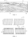
- the implant 100 includes a cover component 102 disposed about the exterior of a microcoil 104.
- the cover 102 and coil 104 may be employed with known bare platinum coil (BPC) based techniques and processes, for example, micro-catheter delivery and radiopacity/visualization, and in conjunction certain known accessories.
- BPC bare platinum coil
- the coil 104 may be formed by helically winding a wire 202 and heat setting it into shape such that it forms a lumen 204.
- the diameter 206 of the lumen 204 is sometimes referred to as the primary diameter.
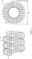
- the coil 104 can take a secondary shape (e.g., helical or complex loops) as shown, for example, in FIG. 3 .
- the secondary shape can have a secondary diameter 302.
- the cover 102 may be compatible with framing, filing, and finishing coils.
- covered framing coils exhibit better fixation, in their secondary shape, of the secondary diameter 302 upon deployment of the implant 100 into a vascular disorder, which can result in less "tumbling” or "spinning.” This results in improved stability of the framing coils, as well as improved overall stability of the implant 100 during deployment of filling and finishing coils.
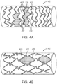
- the cover 102 may include a pattern having pores or cells 106, similar to the pattern found on a medical stent.
- the pattern features open cells 106 as shown in FIG. 4A .
- the pattern features closed cells 106 as shown in FIG. 4B .
- an open cell refers to a cell having greater than two expansion hinges 402 about which the cell expands in a single dimension at a time.
- a closed cell refers to a cell having two or less expansion hinges 402 about which the cell expands in a single dimension at a time.
- the pattern features a hybrid design having both open and closed cells.
- the cover 102 can be formed from either a single strip or multiple strips of material having the pattern (e.g., a through-thickness pattern) cut therein.
- the cover 102 is of unitary construction, which is understood to mean a cover whose cells are formed by the application of a subtractive manufacturing technique to a monolithic piece of material (described in greater detail below).
- a cover of unitary construction is different from a cover in which the cells are formed by multiple overlapping fibers or wires as featured in a fibrous braided cover.
- the cover 102 is disposed about the coil 104 in a helical pattern, but may be disposed in other patterns as well.
- the cover 102 has a constrained configuration while being delivered to a vascular disorder through a delivery device 502 (e.g., a delivery tube or microcatheter) and an expanded configuration after being deployed out of the delivery device 502 into the vascular disorder.
- the cover 102 may be concentric with the coil 104 in the constrained configuration during deployment. After deployment, in the expanded configuration, the cover 102 may remain concentric with the coil 104 or become eccentric with the coil 104. In its constrained configuration, the cover 102 may rest against the exterior of the coil 104, but not extend into its lumen 204.
- the cover 102 In its expanded configuration, with the exception of the contact made at and around the connection portion(s) 1802 (described below, with reference to FIGS. 13 , 18, and 19 ), the cover 102 may be spaced apart from the coil 104, such that in cross-sectional view the cover 102 does not intersect the coil 104. An example of such a cross-sectional view is shown in FIG. 6 .
- Expansion of the cover 102 may be accomplished through, for example, the through-thickness cut patterns and/or shape memory characteristics of the cover's material.
- the spacing and size of the cells 106 may be reduced (e.g., by forces applied by the delivery device 502), thereby shrinking the cover's cross-sectional profile (e.g., outer diameter).
- the spacing and size of the cells 106 may increase (e.g., through the action of the shape memory material), thereby resulting in an expansion of the cover's profile (e.g., outer diameter).
- the cover 102 includes materials with natural shape memory characteristics (e.g., nitinol, shape memory polymers). In other instances, shape memory characteristics are imparted to the cover's material with compressive and/or tensile surface stress management using mechanical or ion implantation techniques.
- shape memory characteristics are imparted to the cover's material with compressive and/or tensile surface stress management using mechanical or ion implantation techniques.
- the cover may have an outer diameter, profile, and biocompatible blood-contacting surface area in a range from 110% to 200% of those parameters of the coil 104 alone.
- the cover 102 can enable the embolic implant 100 to fill a vascular disorder with a significantly greater volume (i.e., packing volume) per unit length of coil 104 than existing devices.
- the packing volume of the implant 100 with a cover 102 in its expanded configuration is between 2 and 7 times as great as the packing volume of the coil 104 without the cover 102.
- An increased packing volume can help achieve greater effective flow diversion of blood away from the aneurysm through enhanced coverage and blockage of the aneurysm neck.
- the expanded profile of the cover 102 results in a larger biocompatible blood-contacting surface area, which can improve stasis of blood-flow within the aneurysm sac.
- the cover 102 may also cover more surface area of the coil 104 than in its constrained configuration.
- FIG. 7 shows, in some embodiments, when the cover 102 is in its constrained configuration, there are gaps 702 in which the cover 102 does not cover the coil 104. In some instances, these gaps 702 are narrowed or closed entirely when the cover 102 enters its expanded configuration, resulting in the cover 102 covering more surface area of the coil 104.
- the cover In addition to the cover's increase of the packing volume and biocompatible blood-contacting surface area of the implant 100, it is also softer and more flexible than existing covers because of its unitary construction. Being of unitary construction allows the cells 106 to be designed such that the cover 102 expands an appropriate amount, but not an excessive amount so as to risk rupture of the aneurysm. Such design is not possible with the inherently stiff wire-on-wire design of existing braided covers. More generally, the pattern of the cover 102 can be designed to include cells 106 having shapes, sizes, and/or configurations to achieve desired flow diversion, blood interaction, and/or force/expansion characteristics of the cover 102. The pattern design can also affect cover 102 flexibility. As a result of its unitary construction, the cover 102 also does not exhibit the fretting (e.g., mechanical and/or corrosive wear) characteristic of fiber braided covers.
- fretting e.g., mechanical and/or corrosive wear
- the cover 102 may also provide a vehicle or platform for the application of multiple treatments and/or therapies including, for example, functionalized and/or bioactive coatings, drug coatings, gene therapies, thrombogenicity control coatings, and surface modifications (e.g., surface texture and/or roughness modifications, ion implantation, and surface charge alterations).
- the cover 102 preserves key coil performance attributes such as, for example, softness and filling capacity.
- the implant 100 may be delivered to the desired site using a microcatheter (e.g., a flexible, small diameter catheter typically, but not necessarily, having an inside diameter between 0.016 inches and 0.021 inches).
- the microcatheter may be guided to the site through the use of an introducer sheath/guidewire.
- Guidewires typically comprise long, torqueable proximal wire sections with flexible distal wire sections designed to be visible using fluoroscopy and to be advanced within tortuous vessels to the desired site, thereby allowing the microcatheter to be advanced over the guidewire to access the desired site.
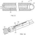
- the implant 100 may be delivered using a delivery device 800.
- the cover 102 is not illustrated in FIG. 8 , but it will be understood that in embodiments in which the cover 102 is directly attached to the coil 104, the cover 102 may be delivered upon delivery of the coil 104.
- the implant 100 may be attached to a delivery pusher 802 containing a retractable release wire 804.
- the delivery pusher 802 may include a proximal shaft 806 made from rigid, metal hypotube to provide good pushability during delivery and stability during detachment of the implant 100; a flexible distal shaft assembly that includes a flexible inner shaft 808 made from a rigid thin-walled polymer tube and flexible outer shaft 810 also made from a rigid thin-walled polymer tube; and an anti-elongation component 812 (e.g., a metallic ribbon/strip).
- the release wire 804 includes a core wire that is, for example, made from 300 series stainless steel, between 35 cm and 75 cm in length, ground on its distal end, and coated on the unground section with polytetrafluoroethylene (PTFE) to reduce friction.
- PTFE polytetrafluoroethylene
- the core wire is about 0.006 inches, wherein 1 inch equals 2,54cm, in diameter, and ground to about 0.002 inches at the tip.
- Attached to the wire 804 can be a coil loop 814 created by winding a segment of wire into a short coil (e.g., about 1 mm in diameter) and a short "hook” and soldering these components to the tip of the release wire 804.
- the coil loop 814 can be made from, for example, 300 series stainless steel wire having a diameter of about 0.001 inches.
- a stationary blade 816 is attached to the distal end of the flexible inner shaft 808.
- the stationary blade 816 may be made from, for example, 300 series stainless steel and attached using an adhesive.
- the stationary blade 816 may be attached behind a polymer tip 818 (e.g., pebax-polyether block amide), which may provide an atraumatic interface and help secure the blade 816 to the inner shaft 808.
- the flexible inner shaft 808 may include a window cutout 820 that allows a detachment suture 902 (described below) to move within the geometry of the blade 816.
- the window 820 may be, for example, hand cut, machine cut, ground, or laser cut.
- a stretch resistant member 902 may attach to the coil 104 and extend along its lumen 204.
- the suture 902 may extend along the lumen 204 from a ball of polymer suture 904 placed (e.g., melted) at a distal end of the coil 104.
- the suture 902 is made of monofilament polypropylene (or, in some cases, of other polymers) having an outer diameter in a range between 0.0005 inches and 0.003 inches.
- the suture 902 may be configured as a single or multifilament (e.g., N ⁇ 2) strand through the lumen 204 of the coil 104.
- the suture 902 can employ strategically placed features on the proximal end of the coil 104 to further aid with containing the working length of the suture 902 through the lumen 204 of the coil 104, which can reduce excessive "pull-out" of the suture 902 during delivery and retraction of the embolic implant 100 through a microcatheter.
- the suture 902 may be attached to the coil 104 before or after the cover 102 has been attached.
- the suture 902 extends from the coil 104, is threaded through the inside diameter of the tip 818 of the delivery pusher 802, through the coil loop 814, and through a front opening 824 of the attached blade 816, is aligned with a notch 826 in the proximal end of the blade 816, and is attached to the flexible inner shaft 808 by a suture locking tube 828.
- the proximal end of the suture 902 may be tied into a knot 830 around the inner shaft 808 and adhesive may be applied to the knot 830 or the knot 830 may be slightly melted to further secure the suture 902 in position.
- FIG. 8 In another embodiment, as shown for example in FIG.
- the suture 902 extending from the coil 104 may be configured as a small loop on its proximal end, which is subsequently looped with a second "sacrificial" detachment loop 1002 that is threaded through a series of ports and channels within the stationary blade component 816 and severed upon detachment actuation, thereby releasing the implant 100 into the aneurysm.
- the proximal shaft 806 may be connected to a handle body 1102 by applying adhesive or employing a press fit.
- the handle body 1102 may include one or more injection molded parts made from, for example, acrylonitrile butadiene styrene (ABS).
- ABS acrylonitrile butadiene styrene
- the proximal end of the release wire 804 may be secured to a handle slider 1106 by threading the wire 804 through a channel in the slider 1106 and bending the wire 804 to form a mechanical hook bond within the slider 1106.
- Other attachment techniques e.g., an adhesive
- the suture 902 may be severed so as to release the embolic implant 100 from the delivery pusher 802 into a vascular disorder. In some instances, this release is accomplished by the retraction of the handle slider 1106 by a user. Since the suture 902 extending from the coil 104 is threaded through the coil loop 814, which is attached to the retractable release wire 804, when the release wire 804 is retracted (by retraction of the handle slider 1106), the coil loop 814 pulls the suture 902 into the blade 816, thereby severing the suture 902 and releasing the implant 100 from the delivery pusher 802 into the aneurysm.
- the handle body 1102 and handle slider 1106 can be assembled in a locked position, which locks the release wire 804 and coil loop 814 in position relative to the blade 816. These parts may be held in place by, for example, detent features molded into the handle body 1102 and handle slider 1106 mating surfaces.
- the delivery device 800 includes an introducer sheath 1202, which protects the embolic implant 100 during sterilization and shipment, and a proximal locking tube 1204, which locks the introducer sheath 1202 in place on the proximal shaft 806.
- the device 800 may include proximal shaft markings 1206, which can be, for example, laser-etched into the hypotube. These markings 1206 may designate to a user, during introduction of the implant 100 into the microcatheter, the position of the implant 100 relative to the microcatheter tip, thereby saving fluoroscopy time and reducing unnecessary x-ray radiation.
- the cover 102 may be manufactured from a flat foil (e.g., a sheet) made from a number of biocompatible, MRI-safe materials, for example metals, absorbable and non-absorbable polymers, ceramics, and composites.
- exemplary metals include nitinol, tantalum and alloys, tungsten and alloys, platinum/tungsten alloy, platinum, platinum iridium, cobalt chrome alloys, magnesium, iron, and stainless steel.
- the foil has a thickness in a range from 5 to 250 microns. Manufacturing the cover 102 from a flat sheet may reduce component cost, ensure raw material availability, and increase component manufacture repeatability and scalability.
- Patterns of cells 106 may be cut into the foil using known cutting techniques including, for example, laser, mechanical, wet chemical, mask or maskless electrochemical, etching/milling, photochemical (e.g., photolithographic) etching/milling, and photoresist/reactive ion or inert gas etch (RIE).
- the cells 106 may be formed using other subtractive manufacturing techniques as well.
- Photochemical and photoelectrochemical machining is a well-established, mature technology that is cost-effective, repeatable, scalable, and capable of producing miniature features with high quality resolution. Given that an implant 100 may require a cover 102 having a length of 50 cm or more, mass exposure and patterning techniques that have been proven possible with photochemical (and electrochemical) machining methods may be effective. In other instances, through-mask cutting and/or ablation using, for example, an excimer laser can be used as well.
- the cover 102 includes multiple separate strips of patterned material, which can be joined at a connection portion 1802.
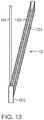
- the cover 102 may include two patterned strips that are helically wound about the coil 104.
- FIG. 13 shows the cover 102 having two strips of material 1302, 1304 that may be helically wound about coil 104.
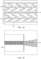
- FIG. 14 shows an example foil that has been cut with a pattern of cells 106.
- the pattern was cut into a single monolithic piece, which was then separated by cut 1402 to create two separate strips 1302, 1304.
- no cut is made in the monolithic piece and the cover 102 includes only a single strip of material.
- multiple cuts are made in the monolithic piece and the cover 102 includes more than two strips of material.
- the coil 104 can be covered with two or more covers 102, each manufactured from a separate monolithic piece.
- the foil may be reverted into a tubular geometry in order to be disposed over the coil 104.
- the foil is reverted into a tubular or cylindrical geometry prior to being placed over the coil 104.
- this process may include forming the patterned foil into a desired tubular geometry about an inner support mandrel 1502 within a rigid tube 1504, which holds the foil in place.
- the foil may then be heat set such that it retains its tubular geometry.
- the foil (now in the shape of cover 102) can be simultaneously pulled over the coil 104 and into a holding tube 1602 such that it is in its constrained configuration (e.g., as shown in FIG. 16 ).
- the separate step of reverting the foil into a tubular geometry using the inner support mandrel 1502 and rigid tube 1504 may be bypassed, and the foil may be reverted to its tubular formation at the same time that it is placed in the holding tube 1602 over the coil 104.
- the foil may be heat set into place while within the holding tube 1602.
- the need to revert the foil into a tubular geometry can be bypassed altogether by cutting the pattern into a material already having a tubular geometry rather than a flat foil.
- the cover 102 may be attached to the coil 104 in various ways.
- the distal and/or proximal end of the implant 100 may be exposed and various attachment techniques may be employed (e.g., as shown in FIG. 17 ).
- a non-exclusive list of such attachment techniques includes: mechanical/interference fit, laser welding, spot welding, resistance welding, diffusion bonding, soldering, brazing and/or application of Class III approved medical adhesives or continual coatings.
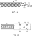
- attachment may occur via a connection portion 1802, an example of which is shown in FIGS. 18 and 19 . As shown in FIG.
- connection portion 1802 may be manufactured from the same monolithic piece of material as the patterned portions. Arms 1804 may also be manufactured to extend from the connection portion 1802 to the patterned portions. In other cases, the connection portion 1802 is manufactured separately and attached to the patterned portions using known techniques. As shown in FIG. 19 , the connection portion 1802 can enable attachment to the coil 104 by being wrapped around the coil 104. In various instances, the connection portion 1802 may include through-thickness features 1902 (e.g., holes or patterns) to facilitate the connection. The connection portion 1802 may be designed to have an inner diameter such that an interference fit with the outer diameter of coil 104 is possible.
- connection portion 1802 is connected directly to the coil 104
- the coil 104 and cover 102 can both be released into a vascular disorder upon release of the coil 104 from the delivery pusher 802 (e.g., as described above with reference to FIGS. 8 through 12 ).
- the embolic implant 100 may be placed into a second tube and then attached to the delivery device 800 (e.g., onto delivery pusher 802).
- the cover 102 is connected only at one of either the proximal or distal end of the coil 104 while remaining unrestrained at the opposite end. In such instances, when the cover 102 expands and/or contracts, it may shorten and/or lengthen at its unrestrained portion, depending on the through-thickness cut pattern of the cover 102. In other instances, the cover 102 is connected to the coil 104 at both the proximal and distal ends of the coil 104.
- the body of the cover i.e., portion between the connected ends
- the arms 804 may lengthen and/or shorten.
- the cover's longitudinal forgiveness, which allows it to lengthen and/or shorten, may be enabled by the through-thickness cut pattern.
- the cover 102 is designed (e.g., a particular through-thickness pattern is implemented) such that when the cover 102 expands and/or contracts it exhibits no, or minimal, shortening and/or lengthening, and in some cases may maintain a length the same as, or close to, that of the coil 104.
Landscapes
- Health & Medical Sciences (AREA)
- Engineering & Computer Science (AREA)
- Life Sciences & Earth Sciences (AREA)
- Surgery (AREA)
- Chemical & Material Sciences (AREA)
- Veterinary Medicine (AREA)
- Medical Informatics (AREA)
- Public Health (AREA)
- General Health & Medical Sciences (AREA)
- Reproductive Health (AREA)
- Vascular Medicine (AREA)
- Nuclear Medicine, Radiotherapy & Molecular Imaging (AREA)
- Animal Behavior & Ethology (AREA)
- Molecular Biology (AREA)
- Biomedical Technology (AREA)
- Heart & Thoracic Surgery (AREA)
- Mechanical Engineering (AREA)
- Optics & Photonics (AREA)
- Physics & Mathematics (AREA)
- Materials Engineering (AREA)
- Organic Chemistry (AREA)
- Metallurgy (AREA)
- Chemical Kinetics & Catalysis (AREA)
- Plasma & Fusion (AREA)
- Electrochemistry (AREA)
- Neurosurgery (AREA)
- General Chemical & Material Sciences (AREA)
- Surgical Instruments (AREA)
- Prostheses (AREA)
- Materials For Medical Uses (AREA)
Applications Claiming Priority (2)
| Application Number | Priority Date | Filing Date | Title |
|---|---|---|---|
| US201462029413P | 2014-07-25 | 2014-07-25 | |
| PCT/US2015/042074 WO2016014985A1 (en) | 2014-07-25 | 2015-07-24 | Covered embolic coils |
Publications (2)
| Publication Number | Publication Date |
|---|---|
| EP3171792A1 EP3171792A1 (en) | 2017-05-31 |
| EP3171792B1 true EP3171792B1 (en) | 2019-01-30 |
Family
ID=53777036
Family Applications (1)
| Application Number | Title | Priority Date | Filing Date |
|---|---|---|---|
| EP15745737.5A Active EP3171792B1 (en) | 2014-07-25 | 2015-07-24 | Covered embolic coils |
Country Status (12)
| Country | Link |
|---|---|
| US (2) | US9987015B2 (pt) |
| EP (1) | EP3171792B1 (pt) |
| JP (1) | JP6601880B2 (pt) |
| KR (1) | KR20170036002A (pt) |
| CN (1) | CN106659505B (pt) |
| AU (1) | AU2015292327A1 (pt) |
| BR (1) | BR112017001319A2 (pt) |
| CA (1) | CA2955953A1 (pt) |
| ES (1) | ES2726910T3 (pt) |
| IL (1) | IL250150A0 (pt) |
| RU (1) | RU2017105842A (pt) |
| WO (1) | WO2016014985A1 (pt) |
Families Citing this family (25)
| Publication number | Priority date | Publication date | Assignee | Title |
|---|---|---|---|---|
| US11357511B2 (en) | 2008-05-01 | 2022-06-14 | Aneuclose Llc | Intrasacular aneurysm occlusion device with globular first configuration and bowl-shaped second configuration |
| US11583289B2 (en) | 2008-05-01 | 2023-02-21 | Aneuclose Llc | Aneurysm-occluding mesh ribbon with a series of loops or segments having distal-to-proximal variation in size, shape, and/or orientation |
| US11471164B2 (en) | 2008-05-01 | 2022-10-18 | Aneuclose Llc | Methods of occluding a cerebral aneurysm by inserting embolic members or material into an intrasacular implant |
| US9918718B2 (en) | 2014-08-08 | 2018-03-20 | DePuy Synthes Products, Inc. | Embolic coil delivery system with retractable mechanical release mechanism |
| JP7144404B2 (ja) | 2016-05-26 | 2022-09-29 | ナノストラクチャーズ・インコーポレイテッド | 神経動脈瘤を塞栓閉塞するためのシステムおよび方法 |
| WO2019036298A1 (en) * | 2017-08-17 | 2019-02-21 | Incumedx, Inc. | FLOW MITIGATION DEVICE |
| US10806462B2 (en) | 2017-12-21 | 2020-10-20 | DePuy Synthes Products, Inc. | Implantable medical device detachment system with split tube and cylindrical coupling |
| CN111936063A (zh) | 2018-01-31 | 2020-11-13 | 纳米结构公司 | 利用薄膜镍钛诺箔的血管闭塞装置 |
| CN112153946A (zh) * | 2018-04-04 | 2020-12-29 | 因库麦迪斯有限公司 | 具有改进的颈部覆盖的栓塞装置 |
| US11147562B2 (en) | 2018-12-12 | 2021-10-19 | DePuy Synthes Products, Inc. | Systems and methods for embolic implant detachment |
| US11253265B2 (en) | 2019-06-18 | 2022-02-22 | DePuy Synthes Products, Inc. | Pull wire detachment for intravascular devices |
| US11207494B2 (en) * | 2019-07-03 | 2021-12-28 | DePuy Synthes Products, Inc. | Medical device delivery member with flexible stretch resistant distal portion |
| US11426174B2 (en) | 2019-10-03 | 2022-08-30 | DePuy Synthes Products, Inc. | Medical device delivery member with flexible stretch resistant mechanical release |
| US11439403B2 (en) | 2019-09-17 | 2022-09-13 | DePuy Synthes Products, Inc. | Embolic coil proximal connecting element and stretch resistant fiber |
| US11376013B2 (en) | 2019-11-18 | 2022-07-05 | DePuy Synthes Products, Inc. | Implant delivery system with braid cup formation |
| US11457922B2 (en) | 2020-01-22 | 2022-10-04 | DePuy Synthes Products, Inc. | Medical device delivery member with flexible stretch resistant distal portion |
| US11432822B2 (en) | 2020-02-14 | 2022-09-06 | DePuy Synthes Products, Inc. | Intravascular implant deployment system |
| US11951026B2 (en) | 2020-06-30 | 2024-04-09 | DePuy Synthes Products, Inc. | Implantable medical device detachment system with flexible braid section |
| US20230061363A1 (en) | 2021-08-31 | 2023-03-02 | Incumedx Inc. | Embolic device with improved neck coverage |
| US11844490B2 (en) | 2021-12-30 | 2023-12-19 | DePuy Synthes Products, Inc. | Suture linkage for inhibiting premature embolic implant deployment |
| US11937824B2 (en) | 2021-12-30 | 2024-03-26 | DePuy Synthes Products, Inc. | Implant detachment systems with a modified pull wire |
| US20230210535A1 (en) * | 2021-12-31 | 2023-07-06 | DePuy Synthes Products, Inc. | Medical device delivery systems with twisting loop wires |
| US11937825B2 (en) | 2022-03-02 | 2024-03-26 | DePuy Synthes Products, Inc. | Hook wire for preventing premature embolic implant detachment |
| US11937826B2 (en) | 2022-03-14 | 2024-03-26 | DePuy Synthes Products, Inc. | Proximal link wire for preventing premature implant detachment |
| US20230414222A1 (en) * | 2022-06-23 | 2023-12-28 | DePuy Synthes Products, Inc. | Detachment indicator for implant deployment |
Citations (2)
| Publication number | Priority date | Publication date | Assignee | Title |
|---|---|---|---|---|
| WO2000074577A1 (en) * | 1999-06-04 | 2000-12-14 | Scimed Life Systems, Inc. | Polymer covered vaso-occlusive devices and methods of producing such devices |
| US6705323B1 (en) * | 1995-06-07 | 2004-03-16 | Conceptus, Inc. | Contraceptive transcervical fallopian tube occlusion devices and methods |
Family Cites Families (53)
| Publication number | Priority date | Publication date | Assignee | Title |
|---|---|---|---|---|
| US3687129A (en) | 1970-10-02 | 1972-08-29 | Abcor Inc | Contraceptive device and method of employing same |
| DE3249027C2 (de) | 1981-09-16 | 1992-02-20 | Medinvent Sa | Chirurgisches Instrument |
| US5078726A (en) | 1989-02-01 | 1992-01-07 | Kreamer Jeffry W | Graft stent and method of repairing blood vessels |
| US5064435A (en) | 1990-06-28 | 1991-11-12 | Schneider (Usa) Inc. | Self-expanding prosthesis having stable axial length |
| US5226911A (en) | 1991-10-02 | 1993-07-13 | Target Therapeutics | Vasoocclusion coil with attached fibrous element(s) |
| US5151105A (en) | 1991-10-07 | 1992-09-29 | Kwan Gett Clifford | Collapsible vessel sleeve implant |
| ATE187086T1 (de) | 1992-09-22 | 1999-12-15 | Target Therapeutics Inc | Anordnung einer lösbaren emboliespiralfeder |
| US5382259A (en) * | 1992-10-26 | 1995-01-17 | Target Therapeutics, Inc. | Vasoocclusion coil with attached tubular woven or braided fibrous covering |
| WO1994011051A1 (en) * | 1992-11-19 | 1994-05-26 | Target Therapeutics, Inc. | Large diameter vasoocclusion coil |
| US5423849A (en) | 1993-01-15 | 1995-06-13 | Target Therapeutics, Inc. | Vasoocclusion device containing radiopaque fibers |
| US5624449A (en) | 1993-11-03 | 1997-04-29 | Target Therapeutics | Electrolytically severable joint for endovascular embolic devices |
| US5658264A (en) | 1994-11-10 | 1997-08-19 | Target Therapeutics, Inc. | High performance spiral-wound catheter |
| US6638291B1 (en) | 1995-04-20 | 2003-10-28 | Micrus Corporation | Three dimensional, low friction vasoocclusive coil, and method of manufacture |
| US6171326B1 (en) | 1998-08-27 | 2001-01-09 | Micrus Corporation | Three dimensional, low friction vasoocclusive coil, and method of manufacture |
| US5624461A (en) | 1995-06-06 | 1997-04-29 | Target Therapeutics, Inc. | Three dimensional in-filling vaso-occlusive coils |
| US5853418A (en) * | 1995-06-30 | 1998-12-29 | Target Therapeutics, Inc. | Stretch resistant vaso-occlusive coils (II) |
| US5582619A (en) | 1995-06-30 | 1996-12-10 | Target Therapeutics, Inc. | Stretch resistant vaso-occlusive coils |
| CA2186768C (en) * | 1995-09-29 | 2000-12-12 | Pete Phong Pham | Anatomically shaped vasoocclusive devices |
| US5792154A (en) * | 1996-04-10 | 1998-08-11 | Target Therapeutics, Inc. | Soft-ended fibered micro vaso-occlusive devices |
| US6322576B1 (en) * | 1997-08-29 | 2001-11-27 | Target Therapeutics, Inc. | Stable coil designs |
| US6159165A (en) | 1997-12-05 | 2000-12-12 | Micrus Corporation | Three dimensional spherical micro-coils manufactured from radiopaque nickel-titanium microstrand |
| US5941888A (en) | 1998-02-18 | 1999-08-24 | Target Therapeutics, Inc. | Vaso-occlusive member assembly with multiple detaching points |
| US5925060A (en) | 1998-03-13 | 1999-07-20 | B. Braun Celsa | Covered self-expanding vascular occlusion device |
| US6254612B1 (en) * | 1998-10-22 | 2001-07-03 | Cordis Neurovascular, Inc. | Hydraulic stent deployment system |
| JP4233173B2 (ja) | 1999-04-28 | 2009-03-04 | ウィリアム・クック・ユーロップ・アークシャセールスカブ | 生体管組織に塞栓コイルを位置決めする組立体 |
| US6379382B1 (en) * | 2000-03-13 | 2002-04-30 | Jun Yang | Stent having cover with drug delivery capability |
| US6530934B1 (en) | 2000-06-06 | 2003-03-11 | Sarcos Lc | Embolic device composed of a linear sequence of miniature beads |
| US6663650B2 (en) | 2000-06-29 | 2003-12-16 | Concentric Medical, Inc. | Systems, methods and devices for removing obstructions from a blood vessel |
| US8313504B2 (en) | 2000-09-18 | 2012-11-20 | Cordis Corporation | Foam matrix embolization device |
| US6635069B1 (en) | 2000-10-18 | 2003-10-21 | Scimed Life Systems, Inc. | Non-overlapping spherical three-dimensional coil |
| US6638245B2 (en) | 2001-06-26 | 2003-10-28 | Concentric Medical, Inc. | Balloon catheter |
| US7060083B2 (en) | 2002-05-20 | 2006-06-13 | Boston Scientific Scimed, Inc. | Foldable vaso-occlusive member |
| EP1526815A1 (en) | 2002-07-31 | 2005-05-04 | MicroVention, Inc. | Three element coaxial vaso-occlusive device |
| US7208003B2 (en) | 2002-09-20 | 2007-04-24 | Cordis Neurovascular, Inc. | Reattachable introducer for a medical device deployment system |
| US7309345B2 (en) | 2003-07-25 | 2007-12-18 | Boston Scientific-Scimed, Inc. | Method and system for delivering an implant utilizing a lumen reducing member |
| US20050137568A1 (en) * | 2003-12-17 | 2005-06-23 | Jones Donald K. | Activatable bioactive implantable medical device and method of use |
| US7485123B2 (en) | 2004-03-01 | 2009-02-03 | Boston Scientific Scimed, Inc. | Complex vaso-occlusive coils |
| US8444668B2 (en) | 2004-09-17 | 2013-05-21 | DePuy Synthes Products, LLC | Expandable vascular occlusion device |
| WO2006032289A1 (de) | 2004-09-22 | 2006-03-30 | Dendron Gmbh | Medizinisches implantat |
| CA2585147A1 (en) | 2004-11-09 | 2006-05-18 | Boston Scientific Limited | Vaso-occlusive devices comprising complex-shape proximal portion and smaller diameter distal portion |
| US20060155324A1 (en) * | 2005-01-12 | 2006-07-13 | Porter Stephen C | Vaso-occlusive devices with attached polymer structures |
| US8002789B2 (en) * | 2005-05-31 | 2011-08-23 | Stryker Corporation | Stretch-resistant vaso-occlusive devices with flexible detachment junctions |
| EP1973680B1 (en) | 2005-11-17 | 2018-01-10 | Microvention, Inc. | Three-dimensional complex coil |
| AU2012202380B2 (en) | 2005-11-17 | 2014-02-13 | Microvention, Inc. | Three-dimensional complex coil |
| US8235048B2 (en) * | 2006-12-01 | 2012-08-07 | Rex Medical, L.P. | Fallopian tube occlusion device |
| JP5608731B2 (ja) | 2009-04-15 | 2014-10-15 | マイクロベンション インコーポレイテッド | インプラント送達システム |
| US9636251B2 (en) * | 2009-10-09 | 2017-05-02 | Bayer Healthcare Llc | Method and apparatus for endometrial ablation in combination with intrafallopian contraceptive devices |
| US8434489B2 (en) * | 2009-10-23 | 2013-05-07 | Conceptus, Inc. | Contraceptive devices and methods |
| WO2011091362A1 (en) * | 2010-01-25 | 2011-07-28 | Jones Donald K | Methods and systems for performing vascular reconstruction |
| US20110245861A1 (en) | 2010-04-05 | 2011-10-06 | Boston Scientific Scimed, Inc. | Vaso-occlusive devices |
| US8998947B2 (en) | 2010-09-10 | 2015-04-07 | Medina Medical, Inc. | Devices and methods for the treatment of vascular defects |
| US9155540B2 (en) | 2012-03-30 | 2015-10-13 | DePuy Synthes Products, Inc. | Embolic coil detachment mechanism with heating element and kicker |
| CN104582634B (zh) | 2012-06-04 | 2017-02-01 | 半影公司 | 动脉瘤闭塞系统和方法 |
-
2015
- 2015-07-24 CA CA2955953A patent/CA2955953A1/en not_active Abandoned
- 2015-07-24 AU AU2015292327A patent/AU2015292327A1/en not_active Abandoned
- 2015-07-24 EP EP15745737.5A patent/EP3171792B1/en active Active
- 2015-07-24 RU RU2017105842A patent/RU2017105842A/ru unknown
- 2015-07-24 US US14/808,550 patent/US9987015B2/en active Active
- 2015-07-24 BR BR112017001319A patent/BR112017001319A2/pt not_active Application Discontinuation
- 2015-07-24 JP JP2017503813A patent/JP6601880B2/ja active Active
- 2015-07-24 WO PCT/US2015/042074 patent/WO2016014985A1/en active Application Filing
- 2015-07-24 ES ES15745737T patent/ES2726910T3/es active Active
- 2015-07-24 KR KR1020177004911A patent/KR20170036002A/ko unknown
- 2015-07-24 CN CN201580040496.8A patent/CN106659505B/zh active Active
-
2017
- 2017-01-17 IL IL250150A patent/IL250150A0/en unknown
-
2018
- 2018-05-01 US US15/968,223 patent/US20180242981A1/en not_active Abandoned
Patent Citations (2)
| Publication number | Priority date | Publication date | Assignee | Title |
|---|---|---|---|---|
| US6705323B1 (en) * | 1995-06-07 | 2004-03-16 | Conceptus, Inc. | Contraceptive transcervical fallopian tube occlusion devices and methods |
| WO2000074577A1 (en) * | 1999-06-04 | 2000-12-14 | Scimed Life Systems, Inc. | Polymer covered vaso-occlusive devices and methods of producing such devices |
Also Published As
| Publication number | Publication date |
|---|---|
| BR112017001319A2 (pt) | 2017-11-14 |
| US20160022275A1 (en) | 2016-01-28 |
| US9987015B2 (en) | 2018-06-05 |
| JP6601880B2 (ja) | 2019-11-06 |
| ES2726910T3 (es) | 2019-10-10 |
| CN106659505A (zh) | 2017-05-10 |
| JP2017527338A (ja) | 2017-09-21 |
| IL250150A0 (en) | 2017-03-30 |
| EP3171792A1 (en) | 2017-05-31 |
| WO2016014985A1 (en) | 2016-01-28 |
| KR20170036002A (ko) | 2017-03-31 |
| US20180242981A1 (en) | 2018-08-30 |
| RU2017105842A (ru) | 2018-08-27 |
| AU2015292327A1 (en) | 2017-02-16 |
| CN106659505B (zh) | 2019-07-02 |
| CA2955953A1 (en) | 2016-01-28 |
Similar Documents
| Publication | Publication Date | Title |
|---|---|---|
| EP3171792B1 (en) | Covered embolic coils | |
| US11911040B2 (en) | Flow attenuation device | |
| US11564817B2 (en) | Procedures for vascular occlusion | |
| US10433851B2 (en) | Braided vascular devices having no end clamps | |
| US20200069313A1 (en) | Aneurysm device and delivery system | |
| WO2017117284A1 (en) | Embolic devices and methods of manufacturing same | |
| JPWO2019036298A5 (pt) | ||
| KR20160130167A (ko) | 리드 프레이밍 코일을 구비한 확장가능 혈관 폐색 장치 | |
| EP1788956A2 (en) | Vascular occlusion device with an embolic mesh ribbon | |
| US20210052278A1 (en) | Vascular occlusion devices utilizing thin film nitinol foils | |
| JP2014512866A (ja) | 血管閉鎖デバイス | |
| AU2008305439B2 (en) | Braided vascular devices having no end clamps |
Legal Events
| Date | Code | Title | Description |
|---|---|---|---|
| STAA | Information on the status of an ep patent application or granted ep patent |
Free format text: STATUS: THE INTERNATIONAL PUBLICATION HAS BEEN MADE |
|
| PUAI | Public reference made under article 153(3) epc to a published international application that has entered the european phase |
Free format text: ORIGINAL CODE: 0009012 |
|
| STAA | Information on the status of an ep patent application or granted ep patent |
Free format text: STATUS: REQUEST FOR EXAMINATION WAS MADE |
|
| 17P | Request for examination filed |
Effective date: 20170117 |
|
| AK | Designated contracting states |
Kind code of ref document: A1 Designated state(s): AL AT BE BG CH CY CZ DE DK EE ES FI FR GB GR HR HU IE IS IT LI LT LU LV MC MK MT NL NO PL PT RO RS SE SI SK SM TR |
|
| AX | Request for extension of the european patent |
Extension state: BA ME |
|
| DAV | Request for validation of the european patent (deleted) | ||
| DAX | Request for extension of the european patent (deleted) | ||
| STAA | Information on the status of an ep patent application or granted ep patent |
Free format text: STATUS: EXAMINATION IS IN PROGRESS |
|
| 17Q | First examination report despatched |
Effective date: 20180209 |
|
| GRAP | Despatch of communication of intention to grant a patent |
Free format text: ORIGINAL CODE: EPIDOSNIGR1 |
|
| STAA | Information on the status of an ep patent application or granted ep patent |
Free format text: STATUS: GRANT OF PATENT IS INTENDED |
|
| INTG | Intention to grant announced |
Effective date: 20180816 |
|
| GRAS | Grant fee paid |
Free format text: ORIGINAL CODE: EPIDOSNIGR3 |
|
| GRAA | (expected) grant |
Free format text: ORIGINAL CODE: 0009210 |
|
| STAA | Information on the status of an ep patent application or granted ep patent |
Free format text: STATUS: THE PATENT HAS BEEN GRANTED |
|
| AK | Designated contracting states |
Kind code of ref document: B1 Designated state(s): AL AT BE BG CH CY CZ DE DK EE ES FI FR GB GR HR HU IE IS IT LI LT LU LV MC MK MT NL NO PL PT RO RS SE SI SK SM TR |
|
| REG | Reference to a national code |
Ref country code: GB Ref legal event code: FG4D |
|
| REG | Reference to a national code |
Ref country code: CH Ref legal event code: EP |
|
| REG | Reference to a national code |
Ref country code: AT Ref legal event code: REF Ref document number: 1092609 Country of ref document: AT Kind code of ref document: T Effective date: 20190215 |
|
| REG | Reference to a national code |
Ref country code: IE Ref legal event code: FG4D |
|
| REG | Reference to a national code |
Ref country code: DE Ref legal event code: R096 Ref document number: 602015024040 Country of ref document: DE |
|
| REG | Reference to a national code |
Ref country code: LT Ref legal event code: MG4D |
|
| REG | Reference to a national code |
Ref country code: NL Ref legal event code: MP Effective date: 20190130 |
|
| PG25 | Lapsed in a contracting state [announced via postgrant information from national office to epo] |
Ref country code: NO Free format text: LAPSE BECAUSE OF FAILURE TO SUBMIT A TRANSLATION OF THE DESCRIPTION OR TO PAY THE FEE WITHIN THE PRESCRIBED TIME-LIMIT Effective date: 20190430 Ref country code: FI Free format text: LAPSE BECAUSE OF FAILURE TO SUBMIT A TRANSLATION OF THE DESCRIPTION OR TO PAY THE FEE WITHIN THE PRESCRIBED TIME-LIMIT Effective date: 20190130 Ref country code: PT Free format text: LAPSE BECAUSE OF FAILURE TO SUBMIT A TRANSLATION OF THE DESCRIPTION OR TO PAY THE FEE WITHIN THE PRESCRIBED TIME-LIMIT Effective date: 20190530 Ref country code: SE Free format text: LAPSE BECAUSE OF FAILURE TO SUBMIT A TRANSLATION OF THE DESCRIPTION OR TO PAY THE FEE WITHIN THE PRESCRIBED TIME-LIMIT Effective date: 20190130 Ref country code: PL Free format text: LAPSE BECAUSE OF FAILURE TO SUBMIT A TRANSLATION OF THE DESCRIPTION OR TO PAY THE FEE WITHIN THE PRESCRIBED TIME-LIMIT Effective date: 20190130 Ref country code: NL Free format text: LAPSE BECAUSE OF FAILURE TO SUBMIT A TRANSLATION OF THE DESCRIPTION OR TO PAY THE FEE WITHIN THE PRESCRIBED TIME-LIMIT Effective date: 20190130 Ref country code: LT Free format text: LAPSE BECAUSE OF FAILURE TO SUBMIT A TRANSLATION OF THE DESCRIPTION OR TO PAY THE FEE WITHIN THE PRESCRIBED TIME-LIMIT Effective date: 20190130 |
|
| REG | Reference to a national code |
Ref country code: AT Ref legal event code: MK05 Ref document number: 1092609 Country of ref document: AT Kind code of ref document: T Effective date: 20190130 |
|
| PG25 | Lapsed in a contracting state [announced via postgrant information from national office to epo] |
Ref country code: LV Free format text: LAPSE BECAUSE OF FAILURE TO SUBMIT A TRANSLATION OF THE DESCRIPTION OR TO PAY THE FEE WITHIN THE PRESCRIBED TIME-LIMIT Effective date: 20190130 Ref country code: GR Free format text: LAPSE BECAUSE OF FAILURE TO SUBMIT A TRANSLATION OF THE DESCRIPTION OR TO PAY THE FEE WITHIN THE PRESCRIBED TIME-LIMIT Effective date: 20190501 Ref country code: HR Free format text: LAPSE BECAUSE OF FAILURE TO SUBMIT A TRANSLATION OF THE DESCRIPTION OR TO PAY THE FEE WITHIN THE PRESCRIBED TIME-LIMIT Effective date: 20190130 Ref country code: BG Free format text: LAPSE BECAUSE OF FAILURE TO SUBMIT A TRANSLATION OF THE DESCRIPTION OR TO PAY THE FEE WITHIN THE PRESCRIBED TIME-LIMIT Effective date: 20190430 Ref country code: IS Free format text: LAPSE BECAUSE OF FAILURE TO SUBMIT A TRANSLATION OF THE DESCRIPTION OR TO PAY THE FEE WITHIN THE PRESCRIBED TIME-LIMIT Effective date: 20190530 Ref country code: RS Free format text: LAPSE BECAUSE OF FAILURE TO SUBMIT A TRANSLATION OF THE DESCRIPTION OR TO PAY THE FEE WITHIN THE PRESCRIBED TIME-LIMIT Effective date: 20190130 |
|
| REG | Reference to a national code |
Ref country code: ES Ref legal event code: FG2A Ref document number: 2726910 Country of ref document: ES Kind code of ref document: T3 Effective date: 20191010 |
|
| PG25 | Lapsed in a contracting state [announced via postgrant information from national office to epo] |
Ref country code: DK Free format text: LAPSE BECAUSE OF FAILURE TO SUBMIT A TRANSLATION OF THE DESCRIPTION OR TO PAY THE FEE WITHIN THE PRESCRIBED TIME-LIMIT Effective date: 20190130 Ref country code: EE Free format text: LAPSE BECAUSE OF FAILURE TO SUBMIT A TRANSLATION OF THE DESCRIPTION OR TO PAY THE FEE WITHIN THE PRESCRIBED TIME-LIMIT Effective date: 20190130 Ref country code: CZ Free format text: LAPSE BECAUSE OF FAILURE TO SUBMIT A TRANSLATION OF THE DESCRIPTION OR TO PAY THE FEE WITHIN THE PRESCRIBED TIME-LIMIT Effective date: 20190130 Ref country code: RO Free format text: LAPSE BECAUSE OF FAILURE TO SUBMIT A TRANSLATION OF THE DESCRIPTION OR TO PAY THE FEE WITHIN THE PRESCRIBED TIME-LIMIT Effective date: 20190130 Ref country code: AL Free format text: LAPSE BECAUSE OF FAILURE TO SUBMIT A TRANSLATION OF THE DESCRIPTION OR TO PAY THE FEE WITHIN THE PRESCRIBED TIME-LIMIT Effective date: 20190130 Ref country code: SK Free format text: LAPSE BECAUSE OF FAILURE TO SUBMIT A TRANSLATION OF THE DESCRIPTION OR TO PAY THE FEE WITHIN THE PRESCRIBED TIME-LIMIT Effective date: 20190130 |
|
| REG | Reference to a national code |
Ref country code: DE Ref legal event code: R097 Ref document number: 602015024040 Country of ref document: DE |
|
| PG25 | Lapsed in a contracting state [announced via postgrant information from national office to epo] |
Ref country code: SM Free format text: LAPSE BECAUSE OF FAILURE TO SUBMIT A TRANSLATION OF THE DESCRIPTION OR TO PAY THE FEE WITHIN THE PRESCRIBED TIME-LIMIT Effective date: 20190130 |
|
| PLBE | No opposition filed within time limit |
Free format text: ORIGINAL CODE: 0009261 |
|
| STAA | Information on the status of an ep patent application or granted ep patent |
Free format text: STATUS: NO OPPOSITION FILED WITHIN TIME LIMIT |
|
| PG25 | Lapsed in a contracting state [announced via postgrant information from national office to epo] |
Ref country code: AT Free format text: LAPSE BECAUSE OF FAILURE TO SUBMIT A TRANSLATION OF THE DESCRIPTION OR TO PAY THE FEE WITHIN THE PRESCRIBED TIME-LIMIT Effective date: 20190130 |
|
| 26N | No opposition filed |
Effective date: 20191031 |
|
| PG25 | Lapsed in a contracting state [announced via postgrant information from national office to epo] |
Ref country code: SI Free format text: LAPSE BECAUSE OF FAILURE TO SUBMIT A TRANSLATION OF THE DESCRIPTION OR TO PAY THE FEE WITHIN THE PRESCRIBED TIME-LIMIT Effective date: 20190130 Ref country code: MC Free format text: LAPSE BECAUSE OF FAILURE TO SUBMIT A TRANSLATION OF THE DESCRIPTION OR TO PAY THE FEE WITHIN THE PRESCRIBED TIME-LIMIT Effective date: 20190130 |
|
| REG | Reference to a national code |
Ref country code: CH Ref legal event code: PL |
|
| PG25 | Lapsed in a contracting state [announced via postgrant information from national office to epo] |
Ref country code: TR Free format text: LAPSE BECAUSE OF FAILURE TO SUBMIT A TRANSLATION OF THE DESCRIPTION OR TO PAY THE FEE WITHIN THE PRESCRIBED TIME-LIMIT Effective date: 20190130 |
|
| REG | Reference to a national code |
Ref country code: BE Ref legal event code: MM Effective date: 20190731 |
|
| PG25 | Lapsed in a contracting state [announced via postgrant information from national office to epo] |
Ref country code: BE Free format text: LAPSE BECAUSE OF NON-PAYMENT OF DUE FEES Effective date: 20190731 Ref country code: CH Free format text: LAPSE BECAUSE OF NON-PAYMENT OF DUE FEES Effective date: 20190731 Ref country code: LU Free format text: LAPSE BECAUSE OF NON-PAYMENT OF DUE FEES Effective date: 20190724 Ref country code: LI Free format text: LAPSE BECAUSE OF NON-PAYMENT OF DUE FEES Effective date: 20190731 |
|
| PG25 | Lapsed in a contracting state [announced via postgrant information from national office to epo] |
Ref country code: IE Free format text: LAPSE BECAUSE OF NON-PAYMENT OF DUE FEES Effective date: 20190724 |
|
| PG25 | Lapsed in a contracting state [announced via postgrant information from national office to epo] |
Ref country code: CY Free format text: LAPSE BECAUSE OF FAILURE TO SUBMIT A TRANSLATION OF THE DESCRIPTION OR TO PAY THE FEE WITHIN THE PRESCRIBED TIME-LIMIT Effective date: 20190130 |
|
| PG25 | Lapsed in a contracting state [announced via postgrant information from national office to epo] |
Ref country code: HU Free format text: LAPSE BECAUSE OF FAILURE TO SUBMIT A TRANSLATION OF THE DESCRIPTION OR TO PAY THE FEE WITHIN THE PRESCRIBED TIME-LIMIT; INVALID AB INITIO Effective date: 20150724 Ref country code: MT Free format text: LAPSE BECAUSE OF FAILURE TO SUBMIT A TRANSLATION OF THE DESCRIPTION OR TO PAY THE FEE WITHIN THE PRESCRIBED TIME-LIMIT Effective date: 20190130 |
|
| PG25 | Lapsed in a contracting state [announced via postgrant information from national office to epo] |
Ref country code: MK Free format text: LAPSE BECAUSE OF FAILURE TO SUBMIT A TRANSLATION OF THE DESCRIPTION OR TO PAY THE FEE WITHIN THE PRESCRIBED TIME-LIMIT Effective date: 20190130 |
|
| P01 | Opt-out of the competence of the unified patent court (upc) registered |
Effective date: 20230509 |
|
| PGFP | Annual fee paid to national office [announced via postgrant information from national office to epo] |
Ref country code: IT Payment date: 20230720 Year of fee payment: 9 Ref country code: GB Payment date: 20230727 Year of fee payment: 9 Ref country code: ES Payment date: 20230804 Year of fee payment: 9 |
|
| PGFP | Annual fee paid to national office [announced via postgrant information from national office to epo] |
Ref country code: FR Payment date: 20230725 Year of fee payment: 9 Ref country code: DE Payment date: 20230727 Year of fee payment: 9 |