EP3170646B1 - Verfahren zur herstellung eines auskleidungsschlauchs zur auskleidung von rohrleitungen sowie vorrichtung zur durchführung des verfahrens - Google Patents
Verfahren zur herstellung eines auskleidungsschlauchs zur auskleidung von rohrleitungen sowie vorrichtung zur durchführung des verfahrens Download PDFInfo
- Publication number
- EP3170646B1 EP3170646B1 EP16002160.6A EP16002160A EP3170646B1 EP 3170646 B1 EP3170646 B1 EP 3170646B1 EP 16002160 A EP16002160 A EP 16002160A EP 3170646 B1 EP3170646 B1 EP 3170646B1
- Authority
- EP
- European Patent Office
- Prior art keywords
- winding mandrel
- inner film
- belt
- guide
- film tube
- Prior art date
- Legal status (The legal status is an assumption and is not a legal conclusion. Google has not performed a legal analysis and makes no representation as to the accuracy of the status listed.)
- Active
Links
Images




Classifications
-
- B—PERFORMING OPERATIONS; TRANSPORTING
- B29—WORKING OF PLASTICS; WORKING OF SUBSTANCES IN A PLASTIC STATE IN GENERAL
- B29C—SHAPING OR JOINING OF PLASTICS; SHAPING OF MATERIAL IN A PLASTIC STATE, NOT OTHERWISE PROVIDED FOR; AFTER-TREATMENT OF THE SHAPED PRODUCTS, e.g. REPAIRING
- B29C63/00—Lining or sheathing, i.e. applying preformed layers or sheathings of plastics; Apparatus therefor
- B29C63/48—Preparation of the surfaces
- B29C63/481—Preparation of the surfaces mechanically
-
- B—PERFORMING OPERATIONS; TRANSPORTING
- B29—WORKING OF PLASTICS; WORKING OF SUBSTANCES IN A PLASTIC STATE IN GENERAL
- B29C—SHAPING OR JOINING OF PLASTICS; SHAPING OF MATERIAL IN A PLASTIC STATE, NOT OTHERWISE PROVIDED FOR; AFTER-TREATMENT OF THE SHAPED PRODUCTS, e.g. REPAIRING
- B29C63/00—Lining or sheathing, i.e. applying preformed layers or sheathings of plastics; Apparatus therefor
- B29C63/0004—Component parts, details or accessories; Auxiliary operations
-
- B—PERFORMING OPERATIONS; TRANSPORTING
- B29—WORKING OF PLASTICS; WORKING OF SUBSTANCES IN A PLASTIC STATE IN GENERAL
- B29C—SHAPING OR JOINING OF PLASTICS; SHAPING OF MATERIAL IN A PLASTIC STATE, NOT OTHERWISE PROVIDED FOR; AFTER-TREATMENT OF THE SHAPED PRODUCTS, e.g. REPAIRING
- B29C63/00—Lining or sheathing, i.e. applying preformed layers or sheathings of plastics; Apparatus therefor
- B29C63/02—Lining or sheathing, i.e. applying preformed layers or sheathings of plastics; Apparatus therefor using sheet or web-like material
- B29C63/024—Lining or sheathing, i.e. applying preformed layers or sheathings of plastics; Apparatus therefor using sheet or web-like material the sheet or web-like material being supported by a moving carriage
-
- B—PERFORMING OPERATIONS; TRANSPORTING
- B29—WORKING OF PLASTICS; WORKING OF SUBSTANCES IN A PLASTIC STATE IN GENERAL
- B29C—SHAPING OR JOINING OF PLASTICS; SHAPING OF MATERIAL IN A PLASTIC STATE, NOT OTHERWISE PROVIDED FOR; AFTER-TREATMENT OF THE SHAPED PRODUCTS, e.g. REPAIRING
- B29C63/00—Lining or sheathing, i.e. applying preformed layers or sheathings of plastics; Apparatus therefor
- B29C63/02—Lining or sheathing, i.e. applying preformed layers or sheathings of plastics; Apparatus therefor using sheet or web-like material
- B29C63/04—Lining or sheathing, i.e. applying preformed layers or sheathings of plastics; Apparatus therefor using sheet or web-like material by folding, winding, bending or the like
- B29C63/06—Lining or sheathing, i.e. applying preformed layers or sheathings of plastics; Apparatus therefor using sheet or web-like material by folding, winding, bending or the like around tubular articles
- B29C63/065—Lining or sheathing, i.e. applying preformed layers or sheathings of plastics; Apparatus therefor using sheet or web-like material by folding, winding, bending or the like around tubular articles continuously
-
- B—PERFORMING OPERATIONS; TRANSPORTING
- B29—WORKING OF PLASTICS; WORKING OF SUBSTANCES IN A PLASTIC STATE IN GENERAL
- B29C—SHAPING OR JOINING OF PLASTICS; SHAPING OF MATERIAL IN A PLASTIC STATE, NOT OTHERWISE PROVIDED FOR; AFTER-TREATMENT OF THE SHAPED PRODUCTS, e.g. REPAIRING
- B29C63/00—Lining or sheathing, i.e. applying preformed layers or sheathings of plastics; Apparatus therefor
- B29C63/02—Lining or sheathing, i.e. applying preformed layers or sheathings of plastics; Apparatus therefor using sheet or web-like material
- B29C63/04—Lining or sheathing, i.e. applying preformed layers or sheathings of plastics; Apparatus therefor using sheet or web-like material by folding, winding, bending or the like
- B29C63/08—Lining or sheathing, i.e. applying preformed layers or sheathings of plastics; Apparatus therefor using sheet or web-like material by folding, winding, bending or the like by winding helically
- B29C63/10—Lining or sheathing, i.e. applying preformed layers or sheathings of plastics; Apparatus therefor using sheet or web-like material by folding, winding, bending or the like by winding helically around tubular articles
- B29C63/105—Lining or sheathing, i.e. applying preformed layers or sheathings of plastics; Apparatus therefor using sheet or web-like material by folding, winding, bending or the like by winding helically around tubular articles continuously
-
- B—PERFORMING OPERATIONS; TRANSPORTING
- B29—WORKING OF PLASTICS; WORKING OF SUBSTANCES IN A PLASTIC STATE IN GENERAL
- B29C—SHAPING OR JOINING OF PLASTICS; SHAPING OF MATERIAL IN A PLASTIC STATE, NOT OTHERWISE PROVIDED FOR; AFTER-TREATMENT OF THE SHAPED PRODUCTS, e.g. REPAIRING
- B29C66/00—General aspects of processes or apparatus for joining preformed parts
- B29C66/50—General aspects of joining tubular articles; General aspects of joining long products, i.e. bars or profiled elements; General aspects of joining single elements to tubular articles, hollow articles or bars; General aspects of joining several hollow-preforms to form hollow or tubular articles
- B29C66/51—Joining tubular articles, profiled elements or bars; Joining single elements to tubular articles, hollow articles or bars; Joining several hollow-preforms to form hollow or tubular articles
- B29C66/53—Joining single elements to tubular articles, hollow articles or bars
- B29C66/532—Joining single elements to the wall of tubular articles, hollow articles or bars
-
- B—PERFORMING OPERATIONS; TRANSPORTING
- B29—WORKING OF PLASTICS; WORKING OF SUBSTANCES IN A PLASTIC STATE IN GENERAL
- B29C—SHAPING OR JOINING OF PLASTICS; SHAPING OF MATERIAL IN A PLASTIC STATE, NOT OTHERWISE PROVIDED FOR; AFTER-TREATMENT OF THE SHAPED PRODUCTS, e.g. REPAIRING
- B29C66/00—General aspects of processes or apparatus for joining preformed parts
- B29C66/80—General aspects of machine operations or constructions and parts thereof
-
- F—MECHANICAL ENGINEERING; LIGHTING; HEATING; WEAPONS; BLASTING
- F16—ENGINEERING ELEMENTS AND UNITS; GENERAL MEASURES FOR PRODUCING AND MAINTAINING EFFECTIVE FUNCTIONING OF MACHINES OR INSTALLATIONS; THERMAL INSULATION IN GENERAL
- F16L—PIPES; JOINTS OR FITTINGS FOR PIPES; SUPPORTS FOR PIPES, CABLES OR PROTECTIVE TUBING; MEANS FOR THERMAL INSULATION IN GENERAL
- F16L11/00—Hoses, i.e. flexible pipes
-
- F—MECHANICAL ENGINEERING; LIGHTING; HEATING; WEAPONS; BLASTING
- F16—ENGINEERING ELEMENTS AND UNITS; GENERAL MEASURES FOR PRODUCING AND MAINTAINING EFFECTIVE FUNCTIONING OF MACHINES OR INSTALLATIONS; THERMAL INSULATION IN GENERAL
- F16L—PIPES; JOINTS OR FITTINGS FOR PIPES; SUPPORTS FOR PIPES, CABLES OR PROTECTIVE TUBING; MEANS FOR THERMAL INSULATION IN GENERAL
- F16L11/00—Hoses, i.e. flexible pipes
- F16L11/24—Hoses, i.e. flexible pipes wound from strips or bands
-
- B—PERFORMING OPERATIONS; TRANSPORTING
- B29—WORKING OF PLASTICS; WORKING OF SUBSTANCES IN A PLASTIC STATE IN GENERAL
- B29C—SHAPING OR JOINING OF PLASTICS; SHAPING OF MATERIAL IN A PLASTIC STATE, NOT OTHERWISE PROVIDED FOR; AFTER-TREATMENT OF THE SHAPED PRODUCTS, e.g. REPAIRING
- B29C53/00—Shaping by bending, folding, twisting, straightening or flattening; Apparatus therefor
- B29C53/56—Winding and joining, e.g. winding spirally
- B29C53/566—Winding and joining, e.g. winding spirally for making tubular articles followed by compression
-
- B—PERFORMING OPERATIONS; TRANSPORTING
- B29—WORKING OF PLASTICS; WORKING OF SUBSTANCES IN A PLASTIC STATE IN GENERAL
- B29C—SHAPING OR JOINING OF PLASTICS; SHAPING OF MATERIAL IN A PLASTIC STATE, NOT OTHERWISE PROVIDED FOR; AFTER-TREATMENT OF THE SHAPED PRODUCTS, e.g. REPAIRING
- B29C53/00—Shaping by bending, folding, twisting, straightening or flattening; Apparatus therefor
- B29C53/56—Winding and joining, e.g. winding spirally
- B29C53/58—Winding and joining, e.g. winding spirally helically
- B29C53/60—Winding and joining, e.g. winding spirally helically using internal forming surfaces, e.g. mandrels
-
- B—PERFORMING OPERATIONS; TRANSPORTING
- B29—WORKING OF PLASTICS; WORKING OF SUBSTANCES IN A PLASTIC STATE IN GENERAL
- B29C—SHAPING OR JOINING OF PLASTICS; SHAPING OF MATERIAL IN A PLASTIC STATE, NOT OTHERWISE PROVIDED FOR; AFTER-TREATMENT OF THE SHAPED PRODUCTS, e.g. REPAIRING
- B29C63/00—Lining or sheathing, i.e. applying preformed layers or sheathings of plastics; Apparatus therefor
- B29C63/26—Lining or sheathing of internal surfaces
- B29C63/34—Lining or sheathing of internal surfaces using tubular layers or sheathings
-
- B—PERFORMING OPERATIONS; TRANSPORTING
- B29—WORKING OF PLASTICS; WORKING OF SUBSTANCES IN A PLASTIC STATE IN GENERAL
- B29K—INDEXING SCHEME ASSOCIATED WITH SUBCLASSES B29B, B29C OR B29D, RELATING TO MOULDING MATERIALS OR TO MATERIALS FOR MOULDS, REINFORCEMENTS, FILLERS OR PREFORMED PARTS, e.g. INSERTS
- B29K2105/00—Condition, form or state of moulded material or of the material to be shaped
- B29K2105/06—Condition, form or state of moulded material or of the material to be shaped containing reinforcements, fillers or inserts
- B29K2105/08—Condition, form or state of moulded material or of the material to be shaped containing reinforcements, fillers or inserts of continuous length, e.g. cords, rovings, mats, fabrics, strands or yarns
- B29K2105/0872—Prepregs
-
- B—PERFORMING OPERATIONS; TRANSPORTING
- B29—WORKING OF PLASTICS; WORKING OF SUBSTANCES IN A PLASTIC STATE IN GENERAL
- B29L—INDEXING SCHEME ASSOCIATED WITH SUBCLASS B29C, RELATING TO PARTICULAR ARTICLES
- B29L2009/00—Layered products
-
- B—PERFORMING OPERATIONS; TRANSPORTING
- B29—WORKING OF PLASTICS; WORKING OF SUBSTANCES IN A PLASTIC STATE IN GENERAL
- B29L—INDEXING SCHEME ASSOCIATED WITH SUBCLASS B29C, RELATING TO PARTICULAR ARTICLES
- B29L2023/00—Tubular articles
- B29L2023/005—Hoses, i.e. flexible
Definitions
- the invention relates to a device for producing a lining hose for lining pipelines according to the preamble of claim 1.
- lining hoses are increasingly being used, which are referred to as "inliners” and consist of a fiber material, in particular glass fiber fabric, which is impregnated with a liquid reaction resin, which after the lining hose is drawn into the pipeline and expanded the same is cured with the help of compressed air by light from a radiation source.
- Such a lining tube and a method and a device for producing such are for example from FIG DE 198 23 714 C2 known.
- the lining tube is produced by winding the resin-soaked fiber tapes in a winding device in an overlapping manner onto an inner film tube that is permeable to UV light, which is previously pulled onto a cantilevered holding tube, at the end of which there is a winding mandrel over which the inner film tube during the winding process is pulled.
- the winding mandrel has a guide device with electrically driven revolving belts that contact the inner film tube from the inside during production and convey it via the winding mandrel, as well as an associated take-off device with two revolving take-off rollers that contact the wound lining tube on the outside and from the winding mandrel pull off.
- a device for producing elements made of composite material which comprises a winding mandrel, on the outside of which endlessly circulating traction means designed as chains are arranged, onto which the strip-shaped material is wound to produce the composite material.
- the document gives no indication of designing the traction means as a mushroom-shaped belt, which comprises a central web on its underside and is ball-bearing mounted on both sides.
- a circumferentially closed inner film tube is moved over a winding mandrel of a winding device.
- the inner film tube which is guided on the winding mandrel by means of a guide device, is wrapped with a fiber tape that is impregnated with a liquid reaction resin, which can be cured in particular by UV light.
- the inner film tube is guided via at least two drivelessly revolving endless traction means received on the winding mandrel, in particular belts, which are preferably mounted on ball bearings to reduce friction.
- the inner film tube wrapped with the sliver is conveyed over the winding mandrel during the winding of the sliver exclusively by a take-off device that acts on the sliver from outside.
- the non-drive design of the endless revolving traction means, on which the inner film tube rests, has the advantage that the sensitive inner film tube can be made as long as desired and there is considerable time saving in the production of the lining tubes, since no supply lines have to be laid through the inner film tube.
- the weight of the winding mandrel can be advantageously reduced due to the elimination of electrical drives and mechanical gears, which were previously required to drive the rotating belt, whereby the entire construction of the components for receiving the holding tube on which the winding mandrel is cantilevered , considerably simplified.
- the guide device can be acted upon by an additional counterforce which is directed against the pull-off force exerted by the pull-off device on the lining tube.
- the counterforce is preferably variable, which makes it possible to select the tensile stress exerted on the inner film tube in the longitudinal direction as a function of the diameter of the lining tube and also the material properties of the inner film tube or the wound fiber material in order to improve the production process.
- variable counterforce tension fluctuations in the longitudinal direction of the inner film tube can, if desired, be compensated for by regulating the counterforce in such a way that an essentially constant counterforce is generated and thus the inner film tube during the The entire production process is subjected to an almost constant tensile stress. This prevents local expansion or compression of the sensitive inner film tube and the associated weakening or wrinkling of the film material, and the production quality is increased accordingly.
- a device according to the invention for producing a lining hose for lining pipelines comprises a winding mandrel on which a guide device with at least one circumferential traction means is arranged.
- the inner film tube is pulled over the guide device by a pull-off device, which preferably comprises two pull-off rollers contacting the outside of the lining tube, but alternatively also two or more rotating, driven ones May include straps.
- the guide device comprises an endless revolving traction means which is movable essentially parallel to the surface of the winding mandrel and which is moved via at least two free-running guide rollers received on the winding mandrel, ie via guide rollers that are not coupled to a drive which drives them in the direction of advance of the lining tube.
- the device is characterized in that the endless belt comprises a central web on the underside and is mounted on ball bearings on both sides of the central web, which are attached, for example, to a common carrier body of the guide device.
- the lateral bearing surfaces of the belt preferably extend like a wing over the end faces of the ball bearings so that the ball bearings are completely covered by the belt and the film material of the inner film tube cannot get into the rotating parts of the ball bearings.
- An inverted embodiment is also conceivable, in which the ball bearings are attached in the middle in a longitudinal groove of the belt and are in each case bounded laterally by webs.
- This non-drive configuration of the guide device or guide devices of the winding mandrel enables the circumferentially closed inner film tube to be fed to the winding mandrel, for example from a roll, in any length without prior unwinding and insertion of the control and supply lines.
- the invention has the further advantage that no additional electrical energy is required for the operation of the winding mandrel, since the revolving traction means, which guide the inner film tube during the winding process and tension it in the circumferential direction, and of which at least two are on opposite sides of the winding mandrel are arranged, are driven solely by the pulling force exerted by the trigger device.
- the endless belt preferably has chain link-like reinforcing elements on the underside. These are preferably made of a harder material than the rubber-like material applied to the top.
- the reinforcing elements can be made of engineering plastics, while the top of the belt is made, for example, of a rubber-elastic material, in particular of elastic rubber.
- the embodiment according to the invention also has the advantage that the belt runs in a guided manner and the rolling resistance is thereby again reduced.
- a braking element for example an electric or magnetic eddy current brake, is assigned to at least one guide roller.
- an electrical or magnetic eddy current braking device has the advantage that the force acting on the inner film tube in the opposite direction to the pull-off direction can, if desired, be changed in a targeted manner without brake abrasion, as can be observed, for example, with a mechanical friction brake Liner tube contaminated inside.
- the guide device is assigned an adjusting device for adjusting the diameter of the winding mandrel.
- the adjustment device can, for example, comprise a central shaft extending in the longitudinal direction of the winding mandrel, the rotational movement of which is transmitted at several points via gear wheels to spindle drives or toothed racks which act on the movably mounted guide devices on the winding mandrel.
- the embodiment of the invention described above has the advantage that, by rotating the central shaft, all guide devices can be moved simultaneously in the radial direction. This enables the diameter of the winding mandrel to be increased or decreased substantially uniformly in the radial direction.
- At least one of the guide devices is movably accommodated on the winding mandrel in a plane running perpendicular to the withdrawal direction of the lining tube and is provided with a substantially constant springy elasticity by spring-elastic means that are at least indirectly supported on a part of the winding mandrel that is fixed to the frame Force applied in the radial direction.
- the resilient means can contain, for example, a pneumatic spring element, in particular a bellows cylinder or a pneumatic cylinder, which is acted upon by a compressed air source with compressed air, which has a considerably larger volume, for example a volume 10 to 100 times as large as the volume of the working space of the pneumatic spring element having.
- a pneumatic spring element in particular a bellows cylinder or a pneumatic cylinder, which is acted upon by a compressed air source with compressed air, which has a considerably larger volume, for example a volume 10 to 100 times as large as the volume of the working space of the pneumatic spring element having.
- an inventive device 1 for producing a lining tube 2 for lining pipelines comprises a winding mandrel 6, on which at least one, but preferably two or more guide devices 18 is arranged.
- the lining tube 2 consists of a circumferentially closed inner film tube 4 and at least one fiber band 12, which is wound onto the inner film tube 4 in an overlapping manner by means of a schematically indicated winding device 8 and which is impregnated with a reaction resin that can be hardened in particular by UV light.
- the winding mandrel 6 is attached to a cantilevered holding tube 32, onto which a section of the inner film tube 4 to be processed is drawn and stored in the collapsed state.
- the guide device 18 has an endlessly revolving traction means which is movable essentially parallel to the surface of the winding mandrel 6 and which is preferably designed as a revolving belt 14, over which the inner film tube 4 is pulled by a take-off device 16 containing two traction rollers.
- the endless revolving belt 14 runs over at least two free-running guide rollers 20 rotatably mounted on the winding mandrel 6, which are not driven and which form the reversal points at which the belt 14, or generally speaking the endless traction means, is deflected becomes.
- a method for producing a lining hose 2 for lining pipelines is described below with reference to FIG Figure 1 described.
- the circumferentially closed inner film tube 4 which was previously pushed onto the holding tube 32 by hand, is pulled over the winding mandrel 6 of the winding device 8 by the two pulling rollers of the take-off device 16.
- this is wrapped by a rotation of the winding device 8 with at least one fiber band 12 which is impregnated with a liquid reaction resin which is produced by electromagnetic radiation, in particular by UV light, or can be cured by heat.
- the take-off device 16 moves the inner film tube 4, which, after a few revolutions of the winding device 8 is wrapped with the sliver 12, enters the take-off device 16 as a lining tube 2, over the winding mandrel 6 at a speed coordinated with the rotational movement of the winding device 8.
- the inner film tube 4 is guided in the manner according to the invention exclusively via the drivelessly rotating endless belt 14 of the respective guide devices 18, of which at least two guide devices for small diameters and four, six or even up to eight guide devices can be provided on the winding mandrel 6 for large diameters.
- the inner film tube 4 wrapped with the sliver 12 is made according to the invention during production conveyed exclusively by the take-off device 16 acting on the fiber sliver 12 from outside via the winding mandrel 6.
- the extraction device 16 can additionally or alternatively to the two in Fig. 1
- the take-off rollers 16 shown include one or more driven rollers or driven revolving belts that revolve outside the revolving area of the winding device 8, e.g. below or to the side of the winding mandrel 6, along a non-powered traction means / belt 14 and against the surface of the lining tube 2 in this area are employable.
- the circumferential traction means / belts 14 are positioned on the winding mandrel 6 and have a length such that they are at least partially in the area of the winding device 8, ie in the area of the sliver 12 moved around the inner film tube 4, and partially in the area outside the same circulate.
- the drive of the additional draw-off rollers or revolving belts that can be adjusted externally to the guide devices 18 preferably takes place via electric motors.
- Figure 2 furthermore shows a schematic side view of a guide device 18 according to the invention, in which the endless belt 14 is guided over two deflection rollers 20 arranged at the ends, between which a plurality of ball bearings 26 are arranged along a row, on which the endless belt 14 is supported, when this contacts the inside of the inner film tube 4 with its outside.
- At least one guide device 18 on the winding mandrel 6 can be accommodated by resilient means 28 which, for example, are designed as a spring-damper combination with a spring element 30 and a damping element 31 and which carry the respective guide device.
- the guide devices 18 can also be movably held on the winding mandrel 6 via guides (not shown), for example linear guides with an end stop, the position of a guide device 18 resiliently accommodated on the winding mandrel preferably being set so that it is during the Production process is preferably deflected only up to half of the maximum movement path.
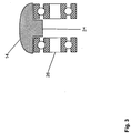
- FIG 3 a schematic cross-sectional representation of the claimed embodiment of the ball-bearing belt 14 according to the invention is shown, which has a central web 24.
- the ball bearings 26 are preferably received on a common shaft, not shown, as is the case, for example, in FIG Figure 5 is indicated by the bolt 34.
- Figure 4 furthermore shows a schematic cross-sectional representation of a belt 14 according to the invention provided with reinforcing elements 22 on the underside.
- the upper side of the belt 14 in this embodiment consists of an elastic, preferably rubber-like material, whereas chain link-like reinforcing elements 22 are arranged on the underside of the belt 14, for example made of a hard plastic material such as polyamide or polycarbonate or made of metal.
- the reinforcement elements 22 serve to further reduce the rolling resistance of the belt 14.
- FIG. 5 shows a not true to scale schematic representation of an adjusting device 40 according to the invention.
- the adjusting device 40 has four guide devices 18, which are each attached to a rack 36 and are guided via linear bearings (not shown in detail) in such a way that they move radially by rotating a central shaft 38 can be.
- the central shaft 38 As a result of the rotation of the central shaft 38, the diameter of the inner film tube 4 guided over it is changed, as defined by the four outer sides of the belts 14.
Landscapes
- Engineering & Computer Science (AREA)
- Manufacturing & Machinery (AREA)
- General Engineering & Computer Science (AREA)
- Mechanical Engineering (AREA)
- Lining Or Joining Of Plastics Or The Like (AREA)
- Moulding By Coating Moulds (AREA)
Description
- Die Erfindung betrifft eine Vorrichtung zur Herstellung eines Auskleidungsschlauchs zur Auskleidung von Rohrleitungen gemäß dem Oberbegriff von Anspruch 1.
- Auf dem Gebiet der grabenlosen Sanierung von defekten Abwasserkanälen werden zunehmend Auskleidungsschläuche eingesetzt, die als "Inliner" bezeichnet werden und aus einem Fasermaterial, insbesondere aus Glasfasergewebe bestehen, welches mit einem flüssigen Reaktionsharz getränkt ist, das nach dem Einziehen des Auskleidungsschlauchs in die Rohrleitung und Expandieren desselben mit Hilfe von Druckluft durch Licht einer Strahlungsquelle ausgehärtet wird.
- Ein solcher Auskleidungsschlauch sowie ein Verfahren und eine Vorrichtung zur Herstellung eines solchen sind beispielsweise aus der
DE 198 23 714 C2 bekannt. - Die Herstellung des Auskleidungsschlauchs erfolgt dadurch, dass die harzgetränkten Faserbänder in einer Wickelvorrichtung überlappend auf einen für UV-Licht durchlässigen Innenfolienschlauch aufgewickelt werden, der zuvor beispielsweise auf ein fliegend gelagertes Halterohr aufgezogen wird, an dessen Ende sich ein Wickeldorn befindet, über den der Innenfolienschlauch während des Wickelvorgangs gezogen wird. Dazu weist der Wickeldorn eine Führungseinrichtung mit elektrisch angetriebenen umlaufenden Riemen auf, die den Innenfolienschlauch während der Produktion von der Innenseite her kontaktieren und über den Wickeldorn fördern, sowie eine zugeordnete Abzugseinrichtung mit zwei umlaufenden Abzugswalzen, die den gewickelten Auskleidungsschlauch auf der Außenseite kontaktieren und vom Wickeldorn abziehen.
- Bei der zuvor beschriebenen Wickelvorrichtung ergibt sich das Problem, dass die elektrisch angetriebene Führungseinrichtungen mit Energie versorgt und die hierfür erforderlichen Versorgungs- und Steuerleitungen vor und während der Produktion eines Auskleidungsschlauchs durch den gesamten umfänglich geschlossenen Innenfolienschlauch hindurch geführt werden müssen. Dies schließt grundsätzlich die Fertigung von Auskleidungsschläuchen mit einer beliebigen Länge auf den zuvor beschriebenen Wickeldornen aus.
- Ein weiteres Problem ergibt sich in diesem Zusammenhang durch die zwingend erforderliche Synchronisation der elektrisch angetriebenen Führungseinrichtungen im Inneren des Auskleidungsschlauchs sowie der ebenfalls elektrisch angetriebenen Abzugseinrichtung auf dessen Außenseite. Treten während der Produktion Spannungsschwankungen in der Längsrichtung des Innenfolienschlauchs, bzw. Auskleidungsschlauchs auf, so führt dies zu einem asynchronen Betrieb der der Abzugseinrichtung und der Führungseinrichtungen, durch die der Innenfolienschlauch entweder lokal gestaucht oder gedehnt wird. Beides kann zu Verschiebungen und Verwerfungen zwischen dem Innenfolienschlauch und der darauf angeordneten gewickelten Lage aus Faserbändern führen, aus denen ein Faltenwurf der Folie des Innenfolienschlauchs resultieren kann, durch den die Qualität des Auskleidungsschlauchs nach dem Aushärten erheblich beeinträchtigt wird. Im schlimmsten Fall kann durch einen solchen Faltenwurf eine Undichtigkeit im Auskleidungsschlauch entstehen, die - wenn der Schaden zunächst unentdeckt bleibt -nach dem Einziehen des Auskleidungsschlauchs in eine zu sanierende Rohrleitung während des sich anschließenden Aufstellens des Auskleidungsschlauchs zum Entweichen der Druckluft sowie einem Zusammenfallen des Liners während des Aushärtens führt.
- Aus der
FR 2732925 A1 - Demgemäß ist es eine Aufgabe der vorliegenden Erfindung, eine Vorrichtung zu schaffen, mit welcher sich ein aus harzgetränkten Faserbändern gewickelter Auskleidungsschlauch mit verringertem Vorrichtungsaufwand fertigen lässt.
- Diese Aufgabe wird erfindungsgemäß durch eine Vorrichtung mit den Merkmalen von Anspruch 1 gelöst.
- Weitere Merkmale der Erfindung sind in den Unteransprüchen beschrieben.
- Bei einem Verfahren zur Herstellung eines Auskleidungsschlauchs zur Auskleidung von Rohrleitungen oder Kanälen, bei welchem die erfindungsgemäße Vorrichtung einsetzbar ist, wird ein umfänglich geschlossener Innenfolienschlauch über einen Wickeldorn einer Wickelvorrichtung bewegt. Der auf dem Wickeldorn mittels einer Führungseinrichtung geführte Innenfolienschlauch wird dabei mit einem Faserband umwickelt, das mit einem flüssigen Reaktionsharz getränkt ist, welches insbesondere durch UV-Licht ausgehärtet werden kann. Hierbei erfolgt die Führung des Innenfolienschlauchs über wenigstens zwei antriebslos umlaufende, am Wickeldorn aufgenommene endlose Zugmittel, insbesondere Riemen, die zur Reduzierung der Reibung vorzugsweise kugelgelagert sind. Der mit dem Faserband umwickelte Innenfolienschlauch wird während des Aufwickelns des Faserbandes ausschließlich durch eine von außen auf das gewickelte Faserband wirkende Abzugseinrichtung über den Wickeldorn gefördert.
- Die antriebslose Ausgestaltung der endlosen umlaufenden Zugmittel, an denen der Innenfolienschlauch anliegt, hat den Vorteil, dass der empfindliche Innenfolienschlauch beliebig lang ausgeführt werden kann und sich eine erhebliche Zeiteinsparung bei der Produktion der Auskleidungsschläuche ergibt, da keine Versorgungsleitungen durch den Innenfolienschlauch gelegt werden müssen. Zudem lässt sich das Gewicht des Wickeldorns aufgrund der entfallenden elektrischen Antriebe und mechanischen Getriebe, die bisher zum antreiben der umlaufenden Riemen erforderlich waren, in vorteilhafter Weise verringern, wodurch sich die gesamte Konstruktion der Komponenten zur Aufnahme des Halterohres, an welchem der Wickeldorn fliegend gelagert wird, erheblich vereinfacht.
- Nach einem weiteren Gedanken kann die Führungseinrichtung mit einer zusätzlichen Gegenkraft beaufschlagt werden, welche der von der Abzugseinrichtung auf den Auskleidungsschlauch ausgeübten Abzugskraft entgegen gerichtet ist.
- Hierdurch ergibt sich der Vorteil, dass der Innenfolienschlauch mit einer definierten Vorspannung beaufschlagt werden kann, durch die eine optimale Anlage des Innenfolienschlauchs am gewickelten Faserband erhalten und so ein Stauchen des Auskleidungsschlauches verhindert wird.
- Bei der zuvor beschriebenen Ausführungsform ist die Gegenkraft vorzugsweise veränderbar, wodurch es ermöglicht wird, die auf den Innenfolienschlauch in Längsrichtung ausgeübte Zugspannung in Abhängigkeit vom Durchmesser des Auskleidungsschlauchs sowie auch den Materialeigenschaften des Innenfolienschlauchs oder des aufgewickelten Fasermaterials zu wählen, um den Produktionsprozess zu verbessern.
- Ein weiterer Vorteil, der mit einer veränderbaren Gegenkraft einhergeht, besteht darin, dass auftretende Spannungsschwankungen in Längsrichtung des Innenfolienschlauchs, gewünschten Falls durch eine Regelung der Gegenkraft in der Weise ausgeglichen werden können, dass eine im Wesentlichen konstante Gegenkraft erzeugt wird und so der Innenfolienschlauch während des gesamten Produktionsprozesses mit einer nahezu konstanten Zugspannung beaufschlagen wird. Dadurch wird ein lokales Dehnen oder Stauchen des empfindlichen Innenfolienschlauchs und eine damit einhergehende Schwächung oder auch ein Faltenwurf des Folienmaterials verhindert und die Fertigungsqualität entsprechend erhöht.
- Gemäß der Erfindung umfasst eine erfindungsgemäße Vorrichtung zur Herstellung eines Auskleidungsschlauchs zur Auskleidung von Rohrleitungen einen Wickeldorn, an dem eine Führungseinrichtung mit wenigstens einem umlaufenden Zugmittel angeordnet ist. Der Innenfolienschlauch wird durch eine Abzugseinrichtung über die Führungseinrichtung gezogen, die vorzugsweise zwei die Außenseite des Auskleidungsschlauchs kontaktierende Abzugswalzen umfasst, jedoch alternativ auch zwei oder mehr umlaufende angetriebene Riemen umfassen kann. Die Führungseinrichtung umfasst ein im Wesentlichen parallel zur Oberfläche des Wickeldorns bewegbares endloses umlaufendes Zugmittel , das über wenigstens zwei am Wickeldorn aufgenommene freilaufende Führungsrollen bewegt wird, d.h. über Führungsrollen, die nicht mit einem Antrieb gekoppelt sind, welcher diese in Vorschubrichtung des Auskleidungsschlauchs antreibt. Die Vorrichtung zeichnet sich dadurch aus, dass der endlose Riemen auf der Unterseite einen Mittensteg umfasst und beidseitig des Mittenstegs auf Kugellagern gelagert ist, die beispielsweise an einem gemeinsamen Trägerkörper der Führungseinrichtung befestigt sind. Hierbei erstrecken sich die seitlichen Auflageflächen des Riemens vorzugsweise flügelartig über die Stirnseiten der Kugellager hinaus, so dass die Kugellager vollständig durch die Riemen abgedeckt sind und das Folienmaterial des Innenfolienschlauchs nicht in die rotierenden Teile der Kugellager gelangen kann. Ebenso ist eine invertierte Ausführungsform denkbar, bei der die Kugellager in der Mitte in einer Längsrille des Riemens angebracht sind und jeweils seitlich davon durch Stege begrenzt werden.
- Diese antriebslose Ausgestaltung der Führungseinrichtung, bzw. Führungseinrichtungen des Wickeldorns, ermöglicht es, dass der umfänglich geschlossene Innenfolienschlauch dem Wickeldorn beispielsweise von einer Rolle aus in einer beliebigen Länge ohne vorheriges Abwickeln und Einführen der Steuerungs- und Versorgungsleitungen zugeführt werden kann.
- Durch die Erfindung ergibt sich der weitere Vorteil, dass für den Betrieb des Wickeldorns keine zusätzliche elektrische Energie benötigt wird, da die umlaufenden Zugmittel, die den Innenfolienschlauch während des Wickelvorgangs führen und in Umfangsrichtung spannen, und von denen wenigstens zwei auf einander gegenüberliegenden Seiten des Wickeldorns angeordnet sind, allein durch die von der Abzugseinrichtung ausgeübte Zugkraft angetrieben werden.
- Dadurch, dass derendlose Riemen über seine Länge hinweg auf Kugellagern geführt ist und einen pilzkopfartigen Querschnitt besitzt, ergibt sich der weitere Vorteil, dass der gegenüber mechanischen Belastungen empfindliche Innenfolienschlauch nahezu auf der gesamten äußeren Oberfläche des Riemens gleichmäßig anliegt.
- Bei einer weiteren Ausführungsform der Erfindung weist der endlose Riemen auf der Unterseite vorzugsweise kettengliedartige Verstärkungselemente auf. Diese sind bevorzugt aus einem härteren Werkstoff gefertigt, als das auf die Oberseite aufgebrachte gummiartige Material. So können die Verstärkungselemente beispielsweise aus Konstruktionskunstoffen gefertigt sein, während die Oberseite der Riemen beispielsweise aus einem gummielastischen Werkstoff, insbesondere aus elastischem Kautschuk, besteht.
- Dies hat den Vorteil, dass sich der Rollwiderstand des Riemens gegenüber einem Riemen, der ausschließlich oder nahezu ausschließlich aus einem gummielastischen Werkstoff besteht, weiter reduziert.
- Die erfindungsgemäße Ausführungsform besitzt ebenfalls den Vorteil, dass der Riemen geführt läuft und der Rollwiderstand dadurch abermals verringert wird.
- Bei der bevorzugten Ausführungsform der Erfindung ist zumindest einer Führungsrolle ein Bremselement, beispielsweise eine elektrische oder magnetische Wirbelstrombremse, zugeordnet.
- Der Einsatz einer elektrischen oder auch magnetischen Wirbelstrom-Bremseinrichtung besitzt den Vorteil, dass die auf den Innenfolienschlauch wirkende, der Abzugsrichtung entgegen gerichtete Kraft, gewünschtenfalls gezielt verändert werden kann, ohne dass entstehender Bremsabrieb, wie er beispielsweise bei einer mechanischen Reibbremse zu beobachten ist, den Auskleidungsschlauch im Inneren verunreinigt.
- Gemäß einer weiteren Ausführungsform der Erfindung ist der Führungseinrichtung eine Verstelleinrichtung zum Verstellen des Durchmessers des Wickeldorns zugeordnet. Die Verstelleinrichtung kann beispielsweise eine sich in Längsrichtung des Wickeldorns erstreckende zentrale Welle umfassen, deren Drehbewegung an mehreren Stellen über Zahnräder auf Spindelantriebe oder Zahnstangen übertragen wird, welche auf die beweglich am Wickeldorn aufgenommenen Führungseinrichtungen wirken.
- Die zuvor beschriebene Ausführungsform der Erfindung besitzt den Vorteil, dass durch ein Verdrehen der zentralen Welle alle Führungseinrichtungen gleichzeitig in radialer Richtung verfahren werden können. Dies ermöglicht es, dass der Durchmesser des Wickeldorns im Wesentlichen gleichmäßig in radialer Richtung vergrößert oder verringert werden kann.
- Nach einem weiteren der Erfindung zugrunde liegenden Gedanken ist wenigstens eine der Führungseinrichtungen in einer senkrecht zur Abzugsrichtung des Auskleidungsschlauchs verlaufenden Ebene beweglich am Wickeldorn aufgenommen und wird durch federelastische Mittel, die sich zumindest indirekt an einem gestellfesten Teil des Wickeldorns abstützen, mit einer im Wesentlichen konstanten federelastischen Kraft in radialer Richtung beaufschlagt.
- Dies hat den Vorteil, dass fertigungsbedingte Durchmesserschwankungen des Innenfolienschlauchs automatisch ausgeglichen werden und die Gefahr einer Faltenbildung infolge von umfänglichen Spannungsschwankungen im Folienmaterial weiter verringert wird.
- Die federelastischen Mittel können beispielsweise ein pneumatisches Federelement, insbesondere ein Balgzylinder oder einen Pneumatikzylinder enthalten, welcher durch eine Druckluftquelle mit Druckluft beaufschlagt wird, die ein erheblich größeres Volumen, beispielsweise ein 10 bis 100 mal so großes Volumen, wie das Volumen des Arbeitsraums des pneumatischen Federelements aufweist.
- Dies ermöglicht es, die auf den Innenfolienschlauch in radialer Richtung wirkende Kraft beispielsweise durch ein Erhöhen oder Erniedrigen des Luftdrucks in der Druckluftquelle einzustellen und damit den Innenfolienschlauch mit unterschiedlichen Vorspannungen zu beaufschlagen.
- Die Erfindung wird nachfolgend mit Bezug auf die Zeichnungen anhand einer bevorzugten Ausführungsform beschrieben.
- In den Zeichnungen zeigen:
- Fig. 1
- Eine schematische Seitenansicht einer erfindungsgemäßen Vorrichtung mit einer angedeuteten Wickelvorrichtung während der Produktion eines Auskleidungsschlauches,
- Fig. 2
- eine schematische Seitenansicht einer erfindungsgemäßen Führungseinrichtung,
- Fig. 3
- eine schematische Querschnittsdarstellung eines erfindungsgemäßen kugelgelagerten Riemens mit Mittensteg,
- Fig. 4
- eine schematische Querschnittsdarstellung eines erfindungsgemäßen Riemens mit Verstärkungselementen, und
- Fig. 5
- eine schematische Darstellung einer erfindungsgemäßen Verstelleinrichtung.
- Wie in der Darstellung von
Fig. 1 gezeigt ist, umfasst eine erfindungsgemäße Vorrichtung 1 zur Herstellung eines Auskleidungsschlauchs 2 zur Auskleidung von Rohrleitungen einen Wickeldorn 6, an dem wenigstens eine, vorzugsweise jedoch zwei oder mehr Führungseinrichtungen 18 angeordnet ist. Der Auskleidungsschlauch 2 besteht aus einem umfänglich geschlossenen Innenfolienschlauch 4 und wenigstens einem auf den Innenfolienschlauch 4 durch eine schematisch angedeutete Wickelvorrichtung 8 überlappend aufgewickelten Faserband 12, das mit einem insbesondere durch UV-Licht härtbaren Reaktionsharz getränkt ist. Wie der Darstellung derFigur 1 entnommen werden kann, ist der Wickeldorn 6 an einem fliegend gelagerten Halterohr 32 befestigt, auf welches ein zu verarbeitender Abschnitt des Innenfolienschlauchs 4 aufgezogen und im zusammengeschobenen Zustand gespeichert wird. - Die Führungseinrichtung 18 weist ein im Wesentlichen parallel zur Oberfläche des Wickeldorns 6 bewegbares endlos umlaufendes Zugmittel auf, welches vorzugsweise als umlaufender Riemen 14 ausgestaltet ist, über welchen hinweg der Innenfolienschlauch 4 durch eine zwei Zugwalzen enthaltene Abzugseinrichtung 16 gezogen wird.
- Wie der Darstellung der
Figuren 1 und2 weiterhin entnommen werden kann, läuft der endlose umlaufende Riemen 14 über wenigstens zwei am Wickeldorn 6 drehbar gelagerte, frei laufende Führungsrollen 20, die nicht angetrieben sind und die die Umkehrpunkte bilden, an denen der Riemen 14, bzw. allgemein gesprochen das endlose Zugmittel, umgelenkt wird. - Ein Verfahren zur Herstellung eines Auskleidungsschlauchs 2 zur Auskleidung von Rohrleitungen wir nachfolgend mit Bezug auf die
Figur 1 beschrieben. Bei diesem wird der umfänglich geschlossene Innenfolienschlauch 4, der zuvor von Hand auf das Halterohr 32 aufgeschoben wurde, durch die beiden Zugwalzen der Abzugseinrichtung 16 über den Wickeldorn 6 der Wickelvorrichtung 8 gezogen. Während des Vorschubs des auf dem Wickeldorn 6 mit Hilfe der Führungseinrichtungen 18 geführten Innenfolienschlauchs 4 wird dieser durch eine Rotation der Wickelvorrichtung 8 mit wenigstens einem Faserband 12 umwickelt, das mit einem flüssigen Reaktionsharz getränkt ist, welches durch elektromagnetische Strahlung, insbesondere durch UV-Licht, oder auch durch Wärme, ausgehärtet werden kann. - Die Abzugseinrichtung 16 bewegt dabei den Innenfolienschlauch 4, der nach einigen Umdrehungen der Wickelvorrichtung 8 mit dem Faserband 12 umwickelt als Auskleidungsschlauch 2 in die Abzugseinrichtung 16 eintritt, in einer auf die Rotationsbewegung der Wickelvorrichtung 8 abgestimmten Geschwindigkeit über den Wickeldorn 6 hinweg. Die Führung des Innenfolienschlauchs 4 erfolgt in erfindungsgemäßer Weise ausschließlich über die antriebslos umlaufenden endlosen Riemen 14 der jeweiligen Führungseinrichtungen 18, von denen bei kleinen Durchmessern wenigstens 2, und bei großen Durchmessern vier, sechs oder gar bis zu acht Führungseinrichtungen am Wickeldorn 6 vorgesehen sein können. Der mit dem Faserband 12 umwickelte Innenfolienschlauch 4 wird während der Produktion erfindungsgemäß ausschließlich durch die von außen auf das Faserband 12 wirkende Abzugseinrichtung 16 über den Wickeldorn 6 gefördert.
- Gemäß einer alternativen, in den Zeichnungen nicht näher dargestellten Ausführungsform der erfindungsgemäßen Vorrichtung 1 kann die Abzugseinrichtung 16 zusätzlich oder alternativ zu den beiden in
Fig. 1 gezeigten Abzugswalzen 16 eine oder auch mehrere angetriebene Walzen oder angetriebene umlaufende Riemen umfassen, die außerhalb des Umlaufbereichs der Wickelvorrichtung 8, z.B. unterhalb oder seitlich vom Wickeldorn 6, entlang eines nicht angetriebenen Zugmittels/Riemens 14 umlaufen und gegen die Oberfläche des Auskleidungsschlauchs 2 in diesem Bereich anstellbar sind. Die umlaufenden Zugmittel/Riemen 14 sind dazu in der Weise am Wickeldorn 6 positioniert und besitzen eine solche Länge, dass diese zumindest teilweise im Bereich der Wickelvorrichtung 8, d.h. im Bereich des um den Innenfolienschlauch 4 herum bewegten Faserbandes 12, und teilweise im Bereich außerhalb derselben umlaufen. Der Antrieb der zusätzlichen extern an die Führungseinrichtungen 18 anstellbaren Abzugswalzen oder umlaufenden Riemen erfolgt dabei vorzugsweise über Elektromotoren. -
Figur 2 zeigt weiterhin eine schematische Seitenansicht einer erfindungsgemäßen Führungseinrichtung 18, bei der der endlose Riemen 14 über zwei an den Enden angeordnete Umlenkrollen 20 geführt ist, zwischen denen eine Vielzahl von Kugellagern 26 entlang einer Reihe angeordnet sind, auf denen sich der endlos umlaufende Riemen 14 abstützt, wenn dieser mit seiner Außenseite die Innenseite des Innenfolienschlauchs 4 kontaktiert. Die Aufnahme wenigstens einer Führungseinrichtung 18 am Wickeldorn 6 kann dabei über federelastische Mittel 28 erfolgen, die beispielsweise als Feder-Dämpfer Kombination mit einem Federelement 30 und einem Dämpfungselement 31 ausgelegt sind und die jeweilige Führungseinrichtung tragen. - Die Führungseinrichtungen 18 können weiterhin über nicht gezeigte Führungen, beispielsweise Linearführungen mit Endanschlag, am Wickeldorn 6 beweglich gehalten werden, wobei die Position einer federnd am Wickeldorn aufgenommenen Führungseinrichtung 18 vorzugsweise so eingestellt wird, dass diese während des Produktionsprozesses vorzugsweise nur bis zur Hälfte des maximalen Bewegungsweges ausgelenkt ist.
- In
Figur 3 ist eine schematische Querschnittsdarstellung der beanspruchten Ausführungsform des kugelgelagerten erfindungsgemäßen Riemens 14 gezeigt, der einen Mittensteg 24 besitzt. Jeweils seitlich des Mittenstegs 24 ist ein Kugellager 26 angeordnet, auf welchem der Riemen 14 in Längsrichtung gelagert ist. Die Kugellager 26 sind vorzugsweise auf einer gemeinsamen, nicht gezeigten Welle aufgenommen, wie dies beispielsweise inFigur 5 durch den Bolzen 34 angedeutet ist. -
Figur 4 zeigt weiterhin eine schematische Querschnittsdarstellung eines auf der Unterseite mit Verstärkungselementen 22 versehenen erfindungsgemäßen Riemens 14. Die Oberseite des Riemens 14 besteht bei dieser Ausführungsform aus einem elastischen, vorzugsweise gummiartigen Material, wohingegen an der Unterseite des Riemens 14 kettengliedartige Verstärkungselemente 22 angeordnet sind, die beispielsweise aus einem harten Kunststoffmaterial wie Polyamid oder Polycarbonat oder auch aus Metall bestehen. Die Verstärkungselemente 22 dienen dazu, den Rollwiderstand des Riemens 14 weiter herab zu setzen. -
Figur 5 zeigt schließlich eine nicht maßstabsgetreue schematische Darstellung einer erfindungsgemäßen Verstelleinrichtung 40. Die Verstelleinrichtung 40 besitzt vier Führungseinrichtungen 18, die jeweils an einer Zahnstange 36 befestigt sind und über nicht näher gezeigte Linearlager in der Weise geführt werden, dass diese durch Rotieren einer zentralen Welle 38 radial verfahren werden können. Dabei wird durch das Verdrehen der zentralen Welle 38 der durch die vier Außenseiten der Riemen 14 definierte Durchmesser des darüber geführten Innenfolienschlauchs 4 verändert. -
- 1
- Erfindungsgemäße Vorrichtung
- 2
- Auskleidungsschlauch
- 4
- Innenfolienschlauch
- 6
- Wickeldorn
- 8
- Wickelvorrichtung
- 12
- Faserband
- 14
- umlaufendes Zugmittel/Riemen
- 16
- Abzugseinrichtung
- 18
- Führungseinrichtung
- 20
- Führungsrolle
- 22
- Kettengliedartige Verstärkungselemente
- 24
- Mittensteg
- 26
- Kugellager
- 28
- Federelastisches Mittel
- 30
- Federelement
- 31
- Dämpfungselement
- 32
- Halterohr
- 34
- Bolzen
- 36
- Rundzahnstange
- 38
- Zentrale Welle
- 40
- Verstelleinrichtu
Claims (7)
- Vorrichtung zur Herstellung eines Auskleidungsschlauchs (2) zur Auskleidung von Rohrleitungen, der einen umfänglich geschlossenen Innenfolienschlauch (4) und wenigstens ein auf den Innenfolienschlauch (4) aufgewickeltes, mit einem härtbaren Reaktionsharz getränktes Faserband (12) umfasst, mit einem Wickeldorn (6), an dem eine Führungseinrichtung (18) angeordnet ist, über welche hinweg der Innenfolienschlauch (4) durch eine Abzugseinrichtung (16) bewegt wird, wobei die Führungseinrichtung ein im Wesentlichen parallel zur Oberfläche des Wickeldorns (6) bewegbares endloses umlaufendes Zugmittel (14) umfasst, das über wenigstens zwei an dem Wickeldorn (6) aufgenommene freilaufende, nicht angetriebene Führungsrollen (20) bewegt wird,
dadurch gekennzeichnet,
dass das Zugmittel ein im Querschnitt pilzkopfartiger Riemen (14) ist und dass der Riemen (14) auf der Unterseite einen Mittensteg (24) umfasst und beidseitig des Mittenstegs kugelgelagert (26) ist. - Vorrichtung nach Anspruch 1,
dadurch gekennzeichnet,
dass der Riemen (14) auf der Unterseite vorzugsweise kettengliedartige Verstärkungselemente (22) aufweist. - Vorrichtung nach einem der Ansprüche 1 oder 2,
dadurch gekennzeichnet,
dass zumindest einer Führungsrolle (20) ein Bremselement, bevorzugt eine elektrische Wirbelstrombremse, zugeordnet ist. - Vorrichtung nach einem der Ansprüche 1 bis 3,
dadurch gekennzeichnet,
dass der Führungseinrichtung eine Verstelleinrichtung (40) zum Verstellen des Durchmessers des Wickeldorns (6) zugeordnet ist. - Vorrichtung nach einem der Ansprüche 1 bis 4,
dadurch gekennzeichnet,
dass die Abzugseinrichtung (16) wenigstens eine angetrieben Walze oder wenigstens einen angetriebenen umlaufenden Riemen umfasst, der außerhalb des Umlaufbereichs der Wickelvorrichtung (8), vorzugsweise unterhalb oder seitlich vom Wickeldorn (6), im Bereich eines endlos umlaufenden Zugmittels (14) umläuft und gegen die Außenseite des Auskleidungsschlauchs (2) anstellbar ist. - Vorrichtung nach einem der Ansprüche 1 bis 5,
dadurch gekennzeichnet,
dass die Führungseinrichtung (18) in radialer Richtung beweglich am Wickeldorn (6) aufgenommen ist und durch federelastische Mittel (28) mit einer im Wesentlichen konstanten federelastischen Kraft in radialer Richtung beaufschlagt wird. - Vorrichtung nach Anspruch 6,
dadurch gekennzeichnet,
dass die federelastischen Mittel (28) ein pneumatisches Federelement (30) umfassen, dass mit einer Druckluftquelle verbindbar ist.
Applications Claiming Priority (1)
| Application Number | Priority Date | Filing Date | Title |
|---|---|---|---|
| DE102015014730.7A DE102015014730A1 (de) | 2015-11-17 | 2015-11-17 | Verfahren zur Herstellung eines Auskleidungsschlauchs zur Auskleidung von Rohrleitungen sowie Vorrichtung zur Durchführung des Verfahrens |
Publications (3)
| Publication Number | Publication Date |
|---|---|
| EP3170646A2 EP3170646A2 (de) | 2017-05-24 |
| EP3170646A3 EP3170646A3 (de) | 2017-08-02 |
| EP3170646B1 true EP3170646B1 (de) | 2020-12-02 |
Family
ID=57144706
Family Applications (1)
| Application Number | Title | Priority Date | Filing Date |
|---|---|---|---|
| EP16002160.6A Active EP3170646B1 (de) | 2015-11-17 | 2016-10-06 | Verfahren zur herstellung eines auskleidungsschlauchs zur auskleidung von rohrleitungen sowie vorrichtung zur durchführung des verfahrens |
Country Status (4)
| Country | Link |
|---|---|
| US (1) | US10377079B2 (de) |
| EP (1) | EP3170646B1 (de) |
| DE (1) | DE102015014730A1 (de) |
| DK (1) | DK3170646T3 (de) |
Cited By (1)
| Publication number | Priority date | Publication date | Assignee | Title |
|---|---|---|---|---|
| EP4570476A1 (de) * | 2023-12-11 | 2025-06-18 | Brandenburger Liner GmbH & Co. KG | Verfahren und vorrichtung zur herstellung eines gewickelten auskleidungsschlauchs |
Families Citing this family (4)
| Publication number | Priority date | Publication date | Assignee | Title |
|---|---|---|---|---|
| CN110480994B (zh) * | 2019-08-28 | 2024-03-22 | 五行科技股份有限公司 | 一种连续增强柔性复合管中心缠绕设备机组 |
| CN111331826B (zh) * | 2020-03-02 | 2021-11-16 | 江苏凯华冷能技术有限公司 | 用于制冷系统的管路包扎装置 |
| CN112606379A (zh) * | 2020-12-28 | 2021-04-06 | 吴功城 | 一种牵引式圆管自动缠带设备 |
| CN113910594B (zh) * | 2021-09-10 | 2023-08-08 | 临海伟星新型建材有限公司 | 一种稳定牵引的缩径设备及其使用方法 |
Family Cites Families (7)
| Publication number | Priority date | Publication date | Assignee | Title |
|---|---|---|---|---|
| US3570749A (en) * | 1968-08-09 | 1971-03-16 | Showa Denko Kk | Heavy duty bags |
| FR2097412A5 (de) * | 1970-07-06 | 1972-03-03 | Cytec France | |
| US4120324A (en) * | 1973-08-01 | 1978-10-17 | Pahl'sche Gummi- und Asbestgesellschaft Paguag | High pressure hose composed of elastomers and embedded reinforcements |
| JPS6179634A (ja) * | 1984-09-28 | 1986-04-23 | Hitachi Zosen Corp | 繊維強化樹脂管製造装置 |
| FR2732925B1 (fr) * | 1995-04-13 | 1997-05-23 | Inst Francais Du Petrole | Dispositif pour fabriquer en continu des elements en composite |
| DE19823714C2 (de) | 1998-05-27 | 2000-07-06 | Joachim Brandenburger | Wickelvorrichtung zum Herstellen eines Schlauches |
| DE19851371A1 (de) * | 1998-11-07 | 2000-05-11 | Bielomatik Leuze & Co | Vorrichtung zum Schaffen einer Lücke in einem geschuppten Bogenstrom |
-
2015
- 2015-11-17 DE DE102015014730.7A patent/DE102015014730A1/de active Pending
-
2016
- 2016-10-06 DK DK16002160.6T patent/DK3170646T3/da active
- 2016-10-06 EP EP16002160.6A patent/EP3170646B1/de active Active
- 2016-11-09 US US15/346,873 patent/US10377079B2/en active Active
Non-Patent Citations (1)
| Title |
|---|
| None * |
Cited By (1)
| Publication number | Priority date | Publication date | Assignee | Title |
|---|---|---|---|---|
| EP4570476A1 (de) * | 2023-12-11 | 2025-06-18 | Brandenburger Liner GmbH & Co. KG | Verfahren und vorrichtung zur herstellung eines gewickelten auskleidungsschlauchs |
Also Published As
| Publication number | Publication date |
|---|---|
| EP3170646A2 (de) | 2017-05-24 |
| US20170136684A1 (en) | 2017-05-18 |
| EP3170646A3 (de) | 2017-08-02 |
| US10377079B2 (en) | 2019-08-13 |
| DK3170646T3 (da) | 2021-02-22 |
| DE102015014730A1 (de) | 2017-05-18 |
Similar Documents
| Publication | Publication Date | Title |
|---|---|---|
| EP3170646A2 (de) | Verfahren zur herstellung eines auskleidungsschlauchs zur auskleidung von rohrleitungen sowie vorrichtung zur durchführung des verfahrens | |
| DE102015012791B4 (de) | Verfahren zur Herstellung eines Auskleidungsschlauchs zur Auskleidung von Rohrleitungen sowie eine Vorrichtung zur Durchführung des Verfahrens | |
| DE1729588A1 (de) | Biegsamer,verstaerkter Schlauch und Verfahren zu seiner Herstellung | |
| EP0406876B1 (de) | Vorrichtung zur Sanierung von Abflussrohren mit einem verharzten Innenrohr | |
| DE2527690C3 (de) | Bandhaspel zum Auf- und Abwickeln von Metallbändern | |
| DE19540427A1 (de) | Vorrichtung zum Speichern und Handhaben einer Stange aus Verbundmaterial | |
| DE102018002544A1 (de) | Verfahren zur Herstellung eines Extrudates | |
| DE102018002545A1 (de) | Verfahren zum Abschneiden eines Extrudates | |
| DE102014219698A1 (de) | Lagerkäfigsegment, Wälzlager und Assemblierungsverfahren | |
| EP3178633B1 (de) | Wickeldorn in einer wickelvorrichtung zur herstellung eines auskleidungsschlauchs zur auskleidung von kanälen und rohrleitungen | |
| EP2604389A2 (de) | Eintreibvorrichtung | |
| DE102024117237A1 (de) | Verfahren und vorrichtung zur herstellung eines gewickelten auskleidungsschlauchs | |
| DE4322114A1 (de) | Umlenkwalze | |
| DE19700785C1 (de) | Vorrichtung zur Herstellung eines Verbundschlauches | |
| DE2027240A1 (en) | Stretching wire or strip | |
| EP0258759A1 (de) | Nasspresse zum Entwässern von Faserstoffbahnen | |
| EP4570476A1 (de) | Verfahren und vorrichtung zur herstellung eines gewickelten auskleidungsschlauchs | |
| DE19524917B4 (de) | Verfahren und Vorrichtung zum Kabeleinziehen | |
| DE2151430A1 (de) | Verfahren und Vorrichtung zum Beschichten von verstaerkten Schlaeuchen | |
| DE1130752B (de) | Verfahren zum Aufbringen eines Reibbelages auf die Antriebstrommel von Foerderbandanlagen | |
| DE10242753A1 (de) | Verfahren und Vorrichtung zur Herstellung eines Verbundschlauchs | |
| DE3230746C2 (de) | Abzugseinrichtung zum Abziehen von kontinuierlich extrudierten Rohren beim Beginn des Extrusionsvorganges | |
| DE2338948C3 (de) | Verfahren zum kontinuierlichen Herstellen von verstärkten Schläuchen aus Elastomeren | |
| DE2635615C2 (de) | Abzugsvorrichtung für aus einer Ziehmatrize austretende metallische Rohre | |
| DE102016110467A1 (de) | Wickelvorrichtung |
Legal Events
| Date | Code | Title | Description |
|---|---|---|---|
| PUAI | Public reference made under article 153(3) epc to a published international application that has entered the european phase |
Free format text: ORIGINAL CODE: 0009012 |
|
| STAA | Information on the status of an ep patent application or granted ep patent |
Free format text: STATUS: THE APPLICATION HAS BEEN PUBLISHED |
|
| AK | Designated contracting states |
Kind code of ref document: A2 Designated state(s): AL AT BE BG CH CY CZ DE DK EE ES FI FR GB GR HR HU IE IS IT LI LT LU LV MC MK MT NL NO PL PT RO RS SE SI SK SM TR |
|
| AX | Request for extension of the european patent |
Extension state: BA ME |
|
| PUAL | Search report despatched |
Free format text: ORIGINAL CODE: 0009013 |
|
| AK | Designated contracting states |
Kind code of ref document: A3 Designated state(s): AL AT BE BG CH CY CZ DE DK EE ES FI FR GB GR HR HU IE IS IT LI LT LU LV MC MK MT NL NO PL PT RO RS SE SI SK SM TR |
|
| AX | Request for extension of the european patent |
Extension state: BA ME |
|
| RIC1 | Information provided on ipc code assigned before grant |
Ipc: B29C 63/10 20060101AFI20170628BHEP |
|
| STAA | Information on the status of an ep patent application or granted ep patent |
Free format text: STATUS: REQUEST FOR EXAMINATION WAS MADE |
|
| 17P | Request for examination filed |
Effective date: 20171128 |
|
| RBV | Designated contracting states (corrected) |
Designated state(s): AL AT BE BG CH CY CZ DE DK EE ES FI FR GB GR HR HU IE IS IT LI LT LU LV MC MK MT NL NO PL PT RO RS SE SI SK SM TR |
|
| STAA | Information on the status of an ep patent application or granted ep patent |
Free format text: STATUS: EXAMINATION IS IN PROGRESS |
|
| 17Q | First examination report despatched |
Effective date: 20200218 |
|
| RAP1 | Party data changed (applicant data changed or rights of an application transferred) |
Owner name: BRANDENBURGER, TIM Owner name: BRANDENBURGER LINER GMBH & CO. KG |
|
| GRAP | Despatch of communication of intention to grant a patent |
Free format text: ORIGINAL CODE: EPIDOSNIGR1 |
|
| STAA | Information on the status of an ep patent application or granted ep patent |
Free format text: STATUS: GRANT OF PATENT IS INTENDED |
|
| INTG | Intention to grant announced |
Effective date: 20200915 |
|
| GRAS | Grant fee paid |
Free format text: ORIGINAL CODE: EPIDOSNIGR3 |
|
| GRAA | (expected) grant |
Free format text: ORIGINAL CODE: 0009210 |
|
| STAA | Information on the status of an ep patent application or granted ep patent |
Free format text: STATUS: THE PATENT HAS BEEN GRANTED |
|
| AK | Designated contracting states |
Kind code of ref document: B1 Designated state(s): AL AT BE BG CH CY CZ DE DK EE ES FI FR GB GR HR HU IE IS IT LI LT LU LV MC MK MT NL NO PL PT RO RS SE SI SK SM TR |
|
| REG | Reference to a national code |
Ref country code: GB Ref legal event code: FG4D Free format text: NOT ENGLISH |
|
| REG | Reference to a national code |
Ref country code: AT Ref legal event code: REF Ref document number: 1340424 Country of ref document: AT Kind code of ref document: T Effective date: 20201215 Ref country code: CH Ref legal event code: EP |
|
| REG | Reference to a national code |
Ref country code: DE Ref legal event code: R096 Ref document number: 502016011812 Country of ref document: DE |
|
| REG | Reference to a national code |
Ref country code: IE Ref legal event code: FG4D Free format text: LANGUAGE OF EP DOCUMENT: GERMAN |
|
| REG | Reference to a national code |
Ref country code: NL Ref legal event code: FP |
|
| REG | Reference to a national code |
Ref country code: DK Ref legal event code: T3 Effective date: 20210219 Ref country code: FI Ref legal event code: FGE |
|
| PG25 | Lapsed in a contracting state [announced via postgrant information from national office to epo] |
Ref country code: NO Free format text: LAPSE BECAUSE OF FAILURE TO SUBMIT A TRANSLATION OF THE DESCRIPTION OR TO PAY THE FEE WITHIN THE PRESCRIBED TIME-LIMIT Effective date: 20210302 Ref country code: RS Free format text: LAPSE BECAUSE OF FAILURE TO SUBMIT A TRANSLATION OF THE DESCRIPTION OR TO PAY THE FEE WITHIN THE PRESCRIBED TIME-LIMIT Effective date: 20201202 Ref country code: GR Free format text: LAPSE BECAUSE OF FAILURE TO SUBMIT A TRANSLATION OF THE DESCRIPTION OR TO PAY THE FEE WITHIN THE PRESCRIBED TIME-LIMIT Effective date: 20210303 |
|
| PG25 | Lapsed in a contracting state [announced via postgrant information from national office to epo] |
Ref country code: BG Free format text: LAPSE BECAUSE OF FAILURE TO SUBMIT A TRANSLATION OF THE DESCRIPTION OR TO PAY THE FEE WITHIN THE PRESCRIBED TIME-LIMIT Effective date: 20210302 Ref country code: SE Free format text: LAPSE BECAUSE OF FAILURE TO SUBMIT A TRANSLATION OF THE DESCRIPTION OR TO PAY THE FEE WITHIN THE PRESCRIBED TIME-LIMIT Effective date: 20201202 Ref country code: LV Free format text: LAPSE BECAUSE OF FAILURE TO SUBMIT A TRANSLATION OF THE DESCRIPTION OR TO PAY THE FEE WITHIN THE PRESCRIBED TIME-LIMIT Effective date: 20201202 Ref country code: PL Free format text: LAPSE BECAUSE OF FAILURE TO SUBMIT A TRANSLATION OF THE DESCRIPTION OR TO PAY THE FEE WITHIN THE PRESCRIBED TIME-LIMIT Effective date: 20201202 |
|
| PG25 | Lapsed in a contracting state [announced via postgrant information from national office to epo] |
Ref country code: HR Free format text: LAPSE BECAUSE OF FAILURE TO SUBMIT A TRANSLATION OF THE DESCRIPTION OR TO PAY THE FEE WITHIN THE PRESCRIBED TIME-LIMIT Effective date: 20201202 |
|
| REG | Reference to a national code |
Ref country code: LT Ref legal event code: MG9D |
|
| PG25 | Lapsed in a contracting state [announced via postgrant information from national office to epo] |
Ref country code: RO Free format text: LAPSE BECAUSE OF FAILURE TO SUBMIT A TRANSLATION OF THE DESCRIPTION OR TO PAY THE FEE WITHIN THE PRESCRIBED TIME-LIMIT Effective date: 20201202 Ref country code: PT Free format text: LAPSE BECAUSE OF FAILURE TO SUBMIT A TRANSLATION OF THE DESCRIPTION OR TO PAY THE FEE WITHIN THE PRESCRIBED TIME-LIMIT Effective date: 20210405 Ref country code: SK Free format text: LAPSE BECAUSE OF FAILURE TO SUBMIT A TRANSLATION OF THE DESCRIPTION OR TO PAY THE FEE WITHIN THE PRESCRIBED TIME-LIMIT Effective date: 20201202 Ref country code: SM Free format text: LAPSE BECAUSE OF FAILURE TO SUBMIT A TRANSLATION OF THE DESCRIPTION OR TO PAY THE FEE WITHIN THE PRESCRIBED TIME-LIMIT Effective date: 20201202 Ref country code: LT Free format text: LAPSE BECAUSE OF FAILURE TO SUBMIT A TRANSLATION OF THE DESCRIPTION OR TO PAY THE FEE WITHIN THE PRESCRIBED TIME-LIMIT Effective date: 20201202 Ref country code: EE Free format text: LAPSE BECAUSE OF FAILURE TO SUBMIT A TRANSLATION OF THE DESCRIPTION OR TO PAY THE FEE WITHIN THE PRESCRIBED TIME-LIMIT Effective date: 20201202 |
|
| REG | Reference to a national code |
Ref country code: DE Ref legal event code: R097 Ref document number: 502016011812 Country of ref document: DE |
|
| PG25 | Lapsed in a contracting state [announced via postgrant information from national office to epo] |
Ref country code: IS Free format text: LAPSE BECAUSE OF FAILURE TO SUBMIT A TRANSLATION OF THE DESCRIPTION OR TO PAY THE FEE WITHIN THE PRESCRIBED TIME-LIMIT Effective date: 20210402 |
|
| PLBE | No opposition filed within time limit |
Free format text: ORIGINAL CODE: 0009261 |
|
| STAA | Information on the status of an ep patent application or granted ep patent |
Free format text: STATUS: NO OPPOSITION FILED WITHIN TIME LIMIT |
|
| PG25 | Lapsed in a contracting state [announced via postgrant information from national office to epo] |
Ref country code: AL Free format text: LAPSE BECAUSE OF FAILURE TO SUBMIT A TRANSLATION OF THE DESCRIPTION OR TO PAY THE FEE WITHIN THE PRESCRIBED TIME-LIMIT Effective date: 20201202 Ref country code: IT Free format text: LAPSE BECAUSE OF FAILURE TO SUBMIT A TRANSLATION OF THE DESCRIPTION OR TO PAY THE FEE WITHIN THE PRESCRIBED TIME-LIMIT Effective date: 20201202 |
|
| 26N | No opposition filed |
Effective date: 20210903 |
|
| PG25 | Lapsed in a contracting state [announced via postgrant information from national office to epo] |
Ref country code: SI Free format text: LAPSE BECAUSE OF FAILURE TO SUBMIT A TRANSLATION OF THE DESCRIPTION OR TO PAY THE FEE WITHIN THE PRESCRIBED TIME-LIMIT Effective date: 20201202 |
|
| PG25 | Lapsed in a contracting state [announced via postgrant information from national office to epo] |
Ref country code: ES Free format text: LAPSE BECAUSE OF FAILURE TO SUBMIT A TRANSLATION OF THE DESCRIPTION OR TO PAY THE FEE WITHIN THE PRESCRIBED TIME-LIMIT Effective date: 20201202 |
|
| PG25 | Lapsed in a contracting state [announced via postgrant information from national office to epo] |
Ref country code: IS Free format text: LAPSE BECAUSE OF FAILURE TO SUBMIT A TRANSLATION OF THE DESCRIPTION OR TO PAY THE FEE WITHIN THE PRESCRIBED TIME-LIMIT Effective date: 20210402 |
|
| GBPC | Gb: european patent ceased through non-payment of renewal fee |
Effective date: 20211006 |
|
| PG25 | Lapsed in a contracting state [announced via postgrant information from national office to epo] |
Ref country code: MC Free format text: LAPSE BECAUSE OF FAILURE TO SUBMIT A TRANSLATION OF THE DESCRIPTION OR TO PAY THE FEE WITHIN THE PRESCRIBED TIME-LIMIT Effective date: 20201202 |
|
| PG25 | Lapsed in a contracting state [announced via postgrant information from national office to epo] |
Ref country code: LU Free format text: LAPSE BECAUSE OF NON-PAYMENT OF DUE FEES Effective date: 20211006 Ref country code: GB Free format text: LAPSE BECAUSE OF NON-PAYMENT OF DUE FEES Effective date: 20211006 |
|
| PG25 | Lapsed in a contracting state [announced via postgrant information from national office to epo] |
Ref country code: IE Free format text: LAPSE BECAUSE OF NON-PAYMENT OF DUE FEES Effective date: 20211006 |
|
| PGFP | Annual fee paid to national office [announced via postgrant information from national office to epo] |
Ref country code: CZ Payment date: 20220926 Year of fee payment: 7 |
|
| PGFP | Annual fee paid to national office [announced via postgrant information from national office to epo] |
Ref country code: NL Payment date: 20221021 Year of fee payment: 7 |
|
| PGFP | Annual fee paid to national office [announced via postgrant information from national office to epo] |
Ref country code: CH Payment date: 20221027 Year of fee payment: 7 Ref country code: BE Payment date: 20221020 Year of fee payment: 7 |
|
| PG25 | Lapsed in a contracting state [announced via postgrant information from national office to epo] |
Ref country code: HU Free format text: LAPSE BECAUSE OF FAILURE TO SUBMIT A TRANSLATION OF THE DESCRIPTION OR TO PAY THE FEE WITHIN THE PRESCRIBED TIME-LIMIT; INVALID AB INITIO Effective date: 20161006 |
|
| P01 | Opt-out of the competence of the unified patent court (upc) registered |
Effective date: 20230417 |
|
| PG25 | Lapsed in a contracting state [announced via postgrant information from national office to epo] |
Ref country code: CY Free format text: LAPSE BECAUSE OF FAILURE TO SUBMIT A TRANSLATION OF THE DESCRIPTION OR TO PAY THE FEE WITHIN THE PRESCRIBED TIME-LIMIT Effective date: 20201202 |
|
| PG25 | Lapsed in a contracting state [announced via postgrant information from national office to epo] |
Ref country code: MK Free format text: LAPSE BECAUSE OF FAILURE TO SUBMIT A TRANSLATION OF THE DESCRIPTION OR TO PAY THE FEE WITHIN THE PRESCRIBED TIME-LIMIT Effective date: 20201202 Ref country code: CZ Free format text: LAPSE BECAUSE OF NON-PAYMENT OF DUE FEES Effective date: 20231006 |
|
| REG | Reference to a national code |
Ref country code: CH Ref legal event code: PL |
|
| REG | Reference to a national code |
Ref country code: NL Ref legal event code: MM Effective date: 20231101 |
|
| REG | Reference to a national code |
Ref country code: BE Ref legal event code: MM Effective date: 20231031 |
|
| PG25 | Lapsed in a contracting state [announced via postgrant information from national office to epo] |
Ref country code: NL Free format text: LAPSE BECAUSE OF NON-PAYMENT OF DUE FEES Effective date: 20231101 Ref country code: CH Free format text: LAPSE BECAUSE OF NON-PAYMENT OF DUE FEES Effective date: 20231031 |
|
| PG25 | Lapsed in a contracting state [announced via postgrant information from national office to epo] |
Ref country code: NL Free format text: LAPSE BECAUSE OF NON-PAYMENT OF DUE FEES Effective date: 20231101 Ref country code: CH Free format text: LAPSE BECAUSE OF NON-PAYMENT OF DUE FEES Effective date: 20231031 |
|
| PG25 | Lapsed in a contracting state [announced via postgrant information from national office to epo] |
Ref country code: BE Free format text: LAPSE BECAUSE OF NON-PAYMENT OF DUE FEES Effective date: 20231031 |
|
| PG25 | Lapsed in a contracting state [announced via postgrant information from national office to epo] |
Ref country code: MT Free format text: LAPSE BECAUSE OF FAILURE TO SUBMIT A TRANSLATION OF THE DESCRIPTION OR TO PAY THE FEE WITHIN THE PRESCRIBED TIME-LIMIT Effective date: 20201202 |
|
| PG25 | Lapsed in a contracting state [announced via postgrant information from national office to epo] |
Ref country code: TR Free format text: LAPSE BECAUSE OF FAILURE TO SUBMIT A TRANSLATION OF THE DESCRIPTION OR TO PAY THE FEE WITHIN THE PRESCRIBED TIME-LIMIT Effective date: 20201202 |
|
| REG | Reference to a national code |
Ref country code: DE Ref legal event code: R082 Ref document number: 502016011812 Country of ref document: DE Representative=s name: KESSELHUT, WOLF, DIPL.-PHYS., DE |
|
| PGFP | Annual fee paid to national office [announced via postgrant information from national office to epo] |
Ref country code: DE Payment date: 20251020 Year of fee payment: 10 |
|
| PGFP | Annual fee paid to national office [announced via postgrant information from national office to epo] |
Ref country code: AT Payment date: 20251021 Year of fee payment: 10 |
|
| PGFP | Annual fee paid to national office [announced via postgrant information from national office to epo] |
Ref country code: FI Payment date: 20251022 Year of fee payment: 10 Ref country code: DK Payment date: 20251023 Year of fee payment: 10 |
|
| PGFP | Annual fee paid to national office [announced via postgrant information from national office to epo] |
Ref country code: FR Payment date: 20251022 Year of fee payment: 10 |